1. Introduction
Bridges, as critical components of transportation infrastructure, are frequently exposed to severe dynamic loads, particularly seismic events, which can lead to significant damage or catastrophic failure [
1,
2]. The vulnerability of bridges to earthquakes, especially multi-span continuous bridges, has been a long-standing concern in civil engineering [
3,
4,
5]. These structures, while efficient for spanning long distances, often exhibit complex dynamic behaviors and stress distributions under seismic excitation, making their protection against seismic events a crucial research area [
2,
6]. Modern seismic resilience philosophy extends beyond conventional life-safety objectives by emphasizing rapid functional recovery and minimal socioeconomic disruption. As demonstrated by Mata et al. through fragility analysis of Chilean bridges, post-earthquake recovery time directly correlates with structural damage mechanisms, where residual displacements exceeding 0.5% can prolong restoration time by 40–60% due to foundation realignment complexities [
7]. Traditional seismic design philosophies primarily focus on enhancing structural strength and ductility, which often leads to larger structural members and increased construction costs. This approach overlooks the resilience economics quantified by Pekcan et al., whose truss girder systems with replaceable dampers reduced rehabilitation costs by 45% through controlled damage localization [
8]. Furthermore, passive seismic control devices, such as viscous dampers and tuned mass dampers, have shown effectiveness in dissipating seismic energy and reducing structural responses [
9,
10,
11]. However, as revealed by Chen et al. in rocking pier systems, near-fault pulses can reduce damper efficiency by 30% due to insufficient energy transfer time [
12]. These devices typically offer fixed damping characteristics, limiting their adaptability to varying seismic intensities and structural demands. Recent resilience-focused innovations include re-centering devices that mitigate residual drifts below 0.1% [
8] and inerter-based systems that enhance overturning stability by 25% [
12], establishing new benchmarks for rapid functional recovery. The emergence of smart materials and semi-active control strategies has opened new avenues for developing more adaptive and efficient seismic protection systems that address both immediate response control and long-term resilience objectives.
Magnetorheological (MR) dampers, which utilize magnetorheological fluids or gels, represent a significant advancement in semi-active control technology due to their ability to rapidly and reversibly change their rheological properties in response to an applied magnetic field [
13,
14,
15]. This inherent adjustability allows MR dampers to exert variable damping forces, making them highly versatile for mitigating vibrations in various engineering applications, including civil structures, automotive suspensions, and prosthetic devices [
16,
17,
18,
19]. Unlike passive dampers, MR dampers can adapt their damping characteristics to optimize structural performance under different excitation levels, consuming minimal power [
20,
21,
22,
23]. This adaptability is particularly crucial for structures subjected to unpredictable and diverse seismic inputs. Recent research efforts have focused on enhancing the performance of MR dampers, exploring novel designs such as multi-coil configurations for higher damping forces [
24,
25] and improved working modes to overcome the limitations of traditional designs [
26,
27]. Furthermore, the integration of advanced control algorithms, including neural networks, has been investigated to improve the precision and responsiveness of MR damper systems [
28]. Despite these advancements, conventional MR dampers often operate based on a single mechanism (e.g., damping), which may not fully address the multifaceted demands of seismic control, particularly the need for enhanced energy dissipation and stiffness or locking during extreme events.
The pursuit of more sophisticated seismic control solutions necessitates the development of multifunctional devices that can seamlessly integrate multiple functionalities. Shear-stiffening gels (SSGs) are a class of smart materials known for their ability to exhibit a dramatic increase in stiffness and energy absorption capacity when subjected to sudden impacts or high-rate deformation [
29,
30]. This rate sensitivity offers a promising avenue for their autonomous adaptation, providing passive stiffening and energy dissipation under dynamic stimuli without an external power input. By combining the autonomous nature and rate sensitivity of SSGs with the magnetic controllability of MR materials, a novel magnetorheological shear-stiffening gel (MRSSG) can be synthesized. This innovative composite material leverages the strengths of both components: the passive, self-enhancing behavior of SSGs under high-frequency loads, and the active, directional control offered by MR materials under magnetic fields [
29,
31]. The integration of such a material into a damper design could lead to a truly multifunctional device capable of addressing a broader spectrum of seismic demands. For instance, while MR fluids have been primarily employed in MR dampers [
32,
33,
34], the development of MRSSGs could offer benefits such as reduced particle sedimentation and enhanced stability, which are critical for ensuring long-term performance and reliability in civil engineering applications. A study of the damping factor in MRSSGs revealed that they have magnetic sensitivity and autonomous response capabilities due to their B-O cross-linked bonds, indicating their potential for dynamic damping performance [
29].
However, existing MR dampers remain constrained by single-mechanism operation (e.g., damping-only designs), which cannot concurrently resolve the following critical seismic challenges: (1) high-frequency load-sharing to redistribute internal forces from fixed to movable piers, preventing localized failure, and (2) low-frequency adaptive damping to suppress displacement responses under varying excitations. This limitation stems from the intrinsic inability of conventional MR fluids or gels to autonomously switch between stiffening and damping modes under dynamic stimuli. To bridge this gap, we synthesize MRSSGs that synergistically combine shear-stiffening (SS) materials, for passive rate-sensitive locking, and magnetorheological (MR) materials for field-controlled damping. Leveraging MRSSGs, we develop the first dual-mode damper capable of context-dependent mechanism switching, thereby enabling holistic seismic resilience for multi-span bridges.
This study aims to address the limitations of conventional single-mechanism dampers by proposing and developing a novel multifunctional MR damper utilizing MRSSGs. This innovative design uniquely combines a high-frequency load-sharing locking mechanism with a low-frequency magnetically controlled damping mechanism. This dual functionality is critical for the seismic control of multi-span continuous bridges. Under intense seismic excitations, the high-frequency load-sharing locking mechanism allows the damper to effectively redistribute internal forces from critical fixed piers to more compliant movable piers. This redistribution mitigates excessive stress concentrations on fixed piers, thereby enhancing the overall structural integrity and preventing localized failures [
35]. Concurrently, under less severe or controlled conditions, the low-frequency magnetically controlled damping mechanism allows for precise adjustment of damping forces, optimizing energy dissipation and structural responses. This research provides theoretical and practical implications for advancing seismic mitigation technologies in large-scale civil structures, particularly multi-span continuous bridges, by offering a highly adaptive and robust control solution that leverages the synergistic properties of MRSSGs for enhanced resilience against seismic hazards.
2. Materials and Methods
2.1. Preparation of MRSSGs
The experimental materials used to synthesize the MRSSGs included boric acid (analytical reagent, Sinopharm Chemical Reagent Co., Ltd., Shanghai, China), polydimethylsiloxane (PDMS, Sinopharm Chemical Reagent Co., Ltd., Shanghai, China), absolute ethyl alcohol (used as a dispersing agent and an analytical reagent, Tianjin BASF Chemical Co., Ltd., Tianjin, China), and the cross-linking agent benzoyl peroxide (BPO, Sinopharm Chemical Reagent Co., Ltd., Shanghai, China).
Figure 1a illustrates the MRSSG preparation process, which was referenced from previous studies [
36,
37]. First, boric acid is heated at 160 °C for 90 min in a vacuum oven, which produces pyroboric acid, accompanied by approximately 30% mass loss. Second, pyroboric acid, PDMS, and ethyl alcohol are combined in a beaker, stirred for 30 min, then heated at 210 °C for 600 min in the vacuum oven. After cooling, the shear-stiffening (SS) matrix is obtained. Finally, carbonyl iron particles (CIPs; average particle size of 3.5 µm; Jiangsu Tianyi Ultrafine Metal Powder Co., Ltd., Huai’an, China) and BPO are added to this matrix. The mixture is stirred for 30 min and cured at 125 °C for 60 min in the vacuum oven. After cooling, the final MRSSG sample is obtained. An image of a prepared sample is shown in
Figure 1b.
The resulting MRSSG can be readily formed into various shapes, such as cylinders, U-shapes, or disks. Under sudden impulsive loads or shocks, the material stiffens to resist deformation. Conversely, minor stimulation easily extends it into thin filaments or compresses it into deep hollows. Applying a magnetic field causes its shape to rapidly align with the magnetic induction lines.
2.2. Characterization of MRSSGs
The rheological properties of the MRSSGs were characterized using an MCR series rheometer (Anton Paar Co., Graz, Austria) with a 25 mm diameter cone–plate geometry (
Figure 2a). All tests were performed at 25 °C with a fixed gap size of 1.0 mm. The rheological tests followed the manufacturer’s protocols (Anton Paar MCR manual v5.3) and prevailing methodologies for magneto-sensitive polymers [
29,
31], with the parameters selected to align with the emerging consensus for MRSSG characterization.
Figure 2b shows the shear storage modulus versus angular frequency for MRSSGs with varying CIP volume fractions. Frequency sweeps from 1 to 100 rad/s were conducted at a constant shear strain of 0.1%. Higher CIP content enhances the absolute SS effect. However, it simultaneously increases the initial shear modulus due to particle filling, which reduces the relative SS effect. For the MRSSG sample with the highest CIP volume fraction at 25 °C, the absolute modulus increase is 0.6145 MPa (approximately twice that of pure SSG), while its relative SS effect (1412.64%) is significantly lower than that of pure SSG (77,584.21%).
As shown in
Figure 2c, the MRSSG sample with highest CIP content exhibits a magneto-induced modulus of 1.5 MPa at 0.5% strain, and a relative MR effect exceeding 600% at 10% strain. In addition, when the magnetic flux density exceeds 0.5 T, the shear storage modulus of the MRSSGs gradually tends toward magnetic saturation.
2.3. Development and Testing of the Multifunctional MR Damper
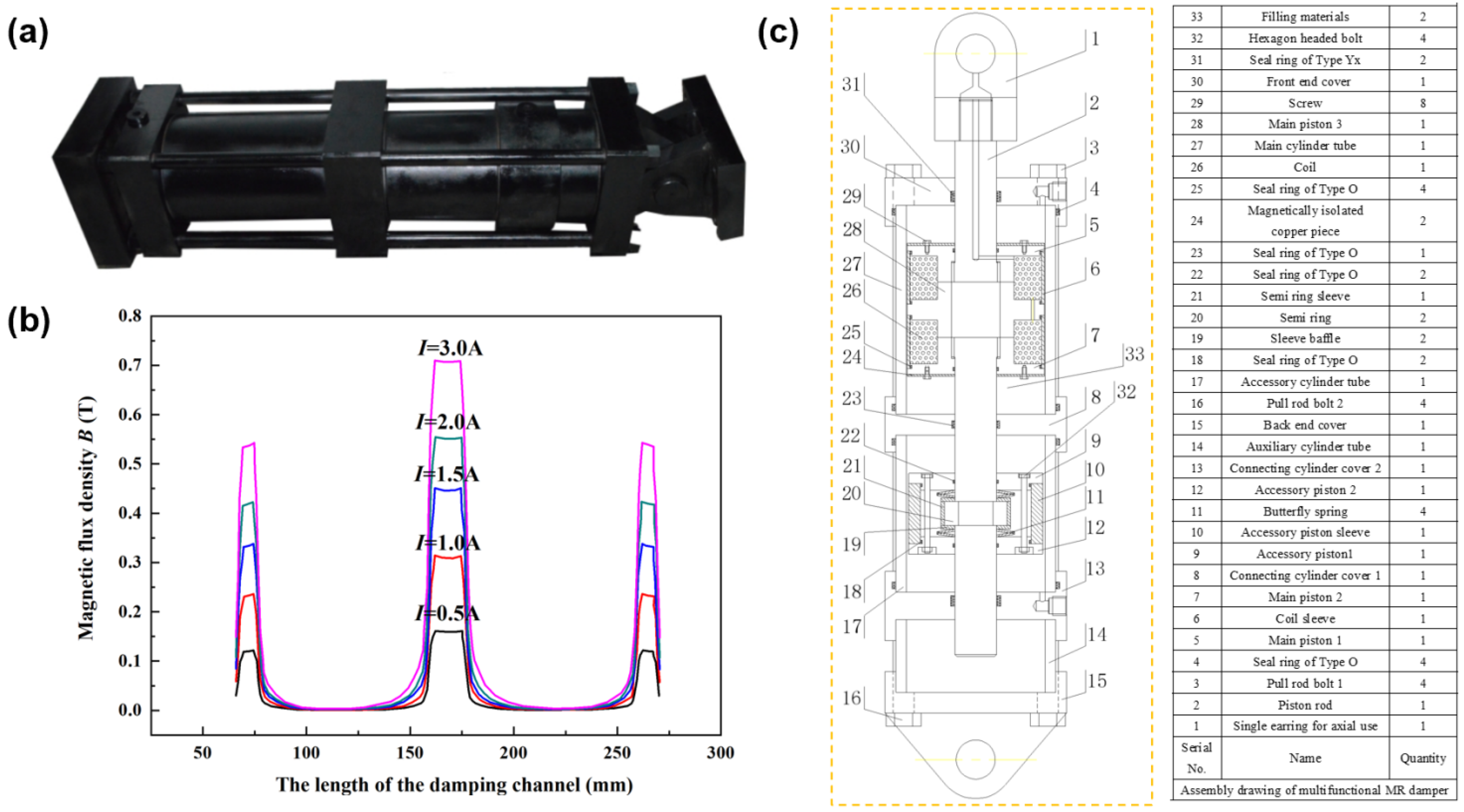
The multifunctional MR damper structure is shown in
Figure 3a,c. Its overall appearance resembles that of a traditional MR damper but features a novel cooperative cylinder formed by integrating the main cylinder (filled with MRSSG and with a CIP volume fraction of 27.29%, exhibiting a high MR effect) and the auxiliary cylinder (filled with pure SSG, offering enhanced shear stiffening to increase overall safety reserves).
Within this structure, the main and auxiliary pistons are mounted on the piston rod. The main piston rigidly connects to the rod via threaded fastening and carries two circular excitation coils wound in opposing directions. Each coil connects to an external power supply through transverse channels, configured in parallel. The auxiliary piston attaches to the rod via a butterfly spring, enabling limited axial movement (constrained by the spring’s maximum compression) to provide decoupling. During operation, the filling materials in both cylinders flow and deform within their respective working gaps.
This design combines a magnetorheologically controlled main cylinder with an accessory cylinder that enables displacement decoupling. It thereby maintains adjustable magnetic-field-dependent damping force while exhibiting significant rate sensitivity. This rate sensitivity acts as a structural lock, effectively dispersing loads under high-frequency or impact conditions. Key structural parameters are detailed in
Table 1.
The shear storage modulus for the MRSSG sample with the highest MR effect shows strong dependence on a magnetic flux density below 0.4 T, stabilizing above this point and reaching magnetic saturation near 0.5 T. To ensure MRSSG saturation within the damper’s working gaps, the magnetic flux density was mapped as shown in
Figure 3b. Our analysis reveals that peak flux density occurs in the central gap (reaching 0.72 T at 3 A), exceeding the value of 0.55 T measured in the end gaps. Both of these values significantly surpass the saturation threshold of 0.5 T.
The dimensions in
Table 1 originate from design optimization targeting three objectives: (1) magnetic saturation (gap flux > 0.5 T per
Figure 3b); (2) structural integrity (stress < 345 MPa yield strength); (3) AASHTO [
38] stroke compliance (locking distance ≤ 12 mm, validated in
Figure 4c).
The multifunctional damper’s energy dissipation primarily occurs through flow and deformation of its filling materials. The rate sensitivity and magnetorheological (MR) effects of the MRSSGs constitute the fundamental mechanisms enabling their environmental adaptation and directional controllability.
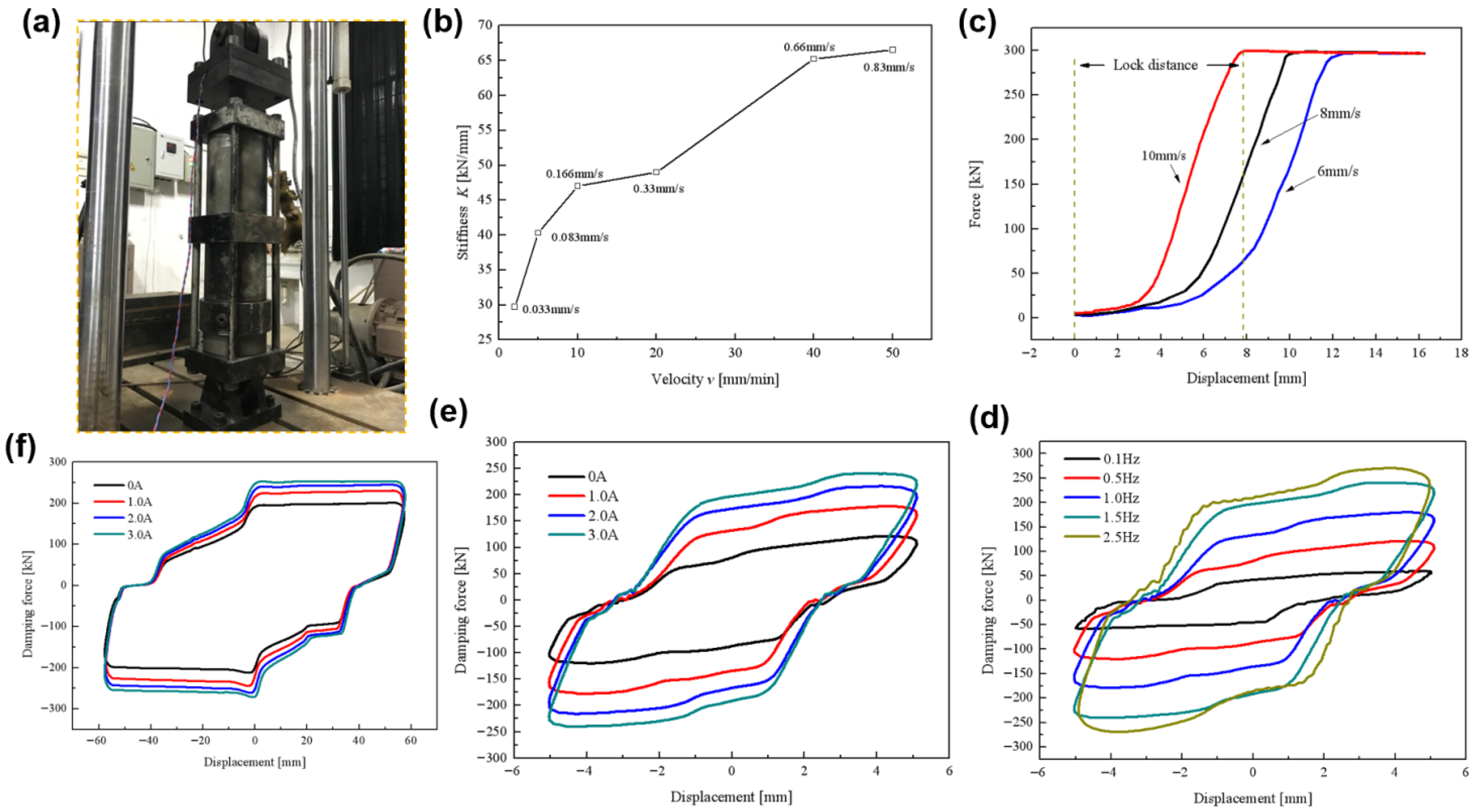
The mechanical properties (rate sensitivity and magnetic control characteristics) of the damper were evaluated using an SDS-300 electro-hydraulic servo testing machine (
Figure 4a). For these tests, we employed displacement-controlled sinusoidal waveforms (0.1–2.5 Hz) for damping characterization, and ramp waveforms (6–10 mm/s) for locking verification. Each loading condition included ≥3 full cycles at ambient temperature (25 °C) per AASHTO [
38]. Although the damper’s stroke limit was 65 mm, for the dynamic tests, we asset the amplitude to 55 mm. In addition, we employed an adjustable DC power supply (maximum current: 3 A). The piston executed reciprocating motion from its central balance position between the cylinder tubes.
Figure 4b demonstrates the increases in the damper’s elastic stiffness with increasing control rate. At 0.033 mm/s, the stiffness remains below 30 kN/mm, while at 0.83 mm/s it exceeds 65 kN/mm—a twofold increase. This confirms the damper’s significant rate sensitivity under slow excitation. Conversely, the rapid testing shows instantaneous structural locking for load transfer. Per AASHTO [
38], the locking distance during fast excitation must be ≤ 12 mm.
The force–displacement curves at constant rates (6, 8, 10 mm/s) in
Figure 4c confirm that the locking distances remain under 12 mm when the force reaches 300 kN, fully complying with AASHTO. Higher rates reduce both locking distance and time: at 10 mm/s, the distance is ~8 mm and the time is 0.8 s, achieving near-instantaneous locking versus > 1 s at lower rates. These results establish the damper functions as a “rate switch” with a 10 mm/s threshold, triggering immediate locking when this threshold is exceeded.
Figure 4d shows enhanced energy dissipation (indicated by larger force–displacement loop areas) with increasing excitation frequency. Between 0.1 and 2.5 Hz and with small displacements, the damping force ranges from 60.3 kN to 269.5 kN—a 4.5-fold increase. Finally,
Figure 4e,f confirm magnetic-field controllability across displacements (5 mm and 55 mm). Notably, at a 55 mm displacement and low frequency, the damping force increases from 212.8 kN to 272.1 kN as the current rises from 0 A to 3 A.
2.4. The Application of the Multifunctional MR Damper in Multi-Span Bridges
The multifunctional MR damper exhibits dual damping characteristics: high-frequency locking load-distribution and low-frequency magnetically controlled vibration reduction. This makes it particularly well-suited for application in multi-span continuous bridge structures, especially those located in regions of high seismic intensity.
In conventional multi-span continuous bridge design, piers equipped with movable bearings do not bear seismic horizontal forces. This is because, when the horizontal force transmitted from a bridge superstructure to a pier equipped with movable bearings exceeds the frictional force of the bearing (approximately 3%), the bearing slips. Consequently, conventional design concentrates all seismic horizontal forces onto piers equipped with fixed bearings, necessitating significantly larger pier cross-sections compared to those housing movable bearings. As illustrated in
Figure 5a, the central main pier, equipped with a fixed bearing, bears the seismic horizontal forces and thus has a large cross-section. In contrast, the other two piers, equipped with movable bearings, share no seismic force.
To address the inability of piers with movable bearings to share seismic loads, multifunctional MR dampers are installed on these movable piers, as displayed in
Figure 5b. During an earthquake event (characterized by rapid excitation), the multifunctional MR damper locks, instantly transforming the movable pier into a fixed pier that begins to share the seismic horizontal forces. This approach substantially reduces the required cross-sectional area of the originally designated fixed pier, giving the original fixed pier and the movable piers comparable cross-sections. This not only reduces construction costs and accelerates the project’s progress but also enhances the bridge’s esthetics. Furthermore, the multifunctional MR damper does not remain locked indefinitely under seismic excitation. When subjected to lower excitation rates, it controls the damping force output via an adjustable current, effectively suppressing the vibration response at the bridge deck support points on the piers, leveraging its advantage of magnetically controlled vibration reduction.
Therefore, by installing multifunctional MR dampers, we aim to enhance the seismic performance of multi-span continuous bridges through two key aspects: (1) optimized load-sharing for more uniform pier design and cost savings, and (2) adaptive vibration control to mitigate responses under varying seismic inputs.
This section focuses on a five-span continuous highway bridge located in a specific city. A simplified model of the bridge and its geometric dimensions are displayed in
Figure 6. The piers are numbered as Pier #1 to Pier #6 from left to right, where Pier #4 is the fixed pier, equipped with a fixed bearing, responsible for carrying the seismic horizontal forces. All other piers (#1, #2, #3, #5, and #6) are movable piers and do not share these seismic forces. Modeling and simulation calculations were carried out using the ABAQUS (version 6.14) commercial finite element software. Seismic input motions were simulated using the El Centro, Koyna, and Wenchuan earthquake waves. To perform a simulation analysis of vibration control on this bridge, several multifunctional MR dampers were installed on its movable piers. The simulation results demonstrate that the multifunctional MR dampers have significant practical potential for suppressing the bridge’s vibration response and enhancing the structure’s seismic performance.
2.5. Finite Element Model of the Multi-Span Continuous Bridge
We established a finite element model of the bridge that employs eight-node hexahedral reduced integration elements (C3D8R) with enhanced hourglass control. The complete model comprises 11,470 nodes and 6780 elements. Specifically, the bridge deck contains 7242 nodes and 4128 elements, and each pier section contains 704 nodes and 442 elements. A fixed bearing, configured as a laminated rubber bearing, is assigned between Pier #4 and the upper box girder. Its coefficient of friction is set to 0.3 according to the Chinese Standard JT/T 391-2009 [
39]. In contrast, pot rubber bearings, serving as movable bearings, connect the upper box girder to each of the other five piers (#1, #2, #3, #5, and #6), allowing relative slip. The coefficient of friction for these movable bearings is set to 0.03 according to Chinese Standard JT/T 4-2004 [
40]. The upper box girder utilizes grade C50 concrete, while the piers are constructed from grade C30 concrete. Material properties are assigned according to Chinese Code JTGD62-2012. Details of the material parameters are provided in
Table 2. Based on the above specifications, a three-dimensional finite element numerical model of the multi-span continuous bridge was established, as illustrated in
Figure 7.
3. Results and Discussion
3.1. Natural-Vibration Characteristics of the Multi-Span Continuous Bridge Structure
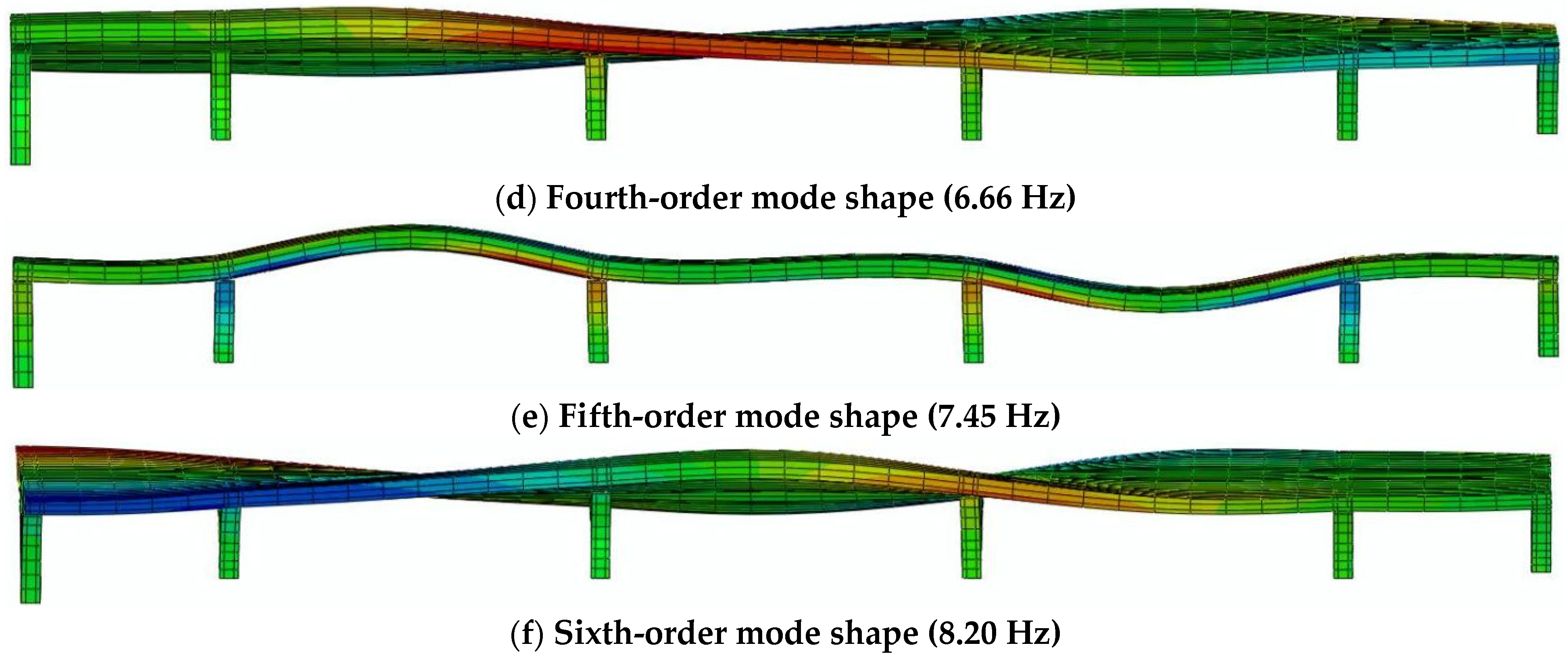
Building upon the model outlined above, we conducted simulations of the dynamic characteristics of the multi-span continuous bridge. These simulations allow us to elucidate the structure’s natural frequencies and mode shape characteristics. The first three calculated natural vibration frequencies of the five-span continuous bridge are 4.90 Hz, 5.60 Hz, and 6.14 Hz. The first six mode shapes of the bridge are presented in
Figure 8. The analysis of the fundamental (first) mode shape reveals a pronounced tendency for bending deformation along the bridge’s longitudinal axis, indicating comparatively lower lateral stiffness in this direction and identifying it as a potential seismic vulnerability. Consequently, the installation of multifunctional MR damping devices along the bridge axis for structural vibration control is both rational and necessary. The modal analysis of the five-span continuous bridge indicates that seismic damage predominantly occurs along the bridge’s longitudinal axis under earthquake excitation. Consequently, eight multifunctional MR dampers were symmetrically installed at the top of each movable pier, connecting the piers to the upper box girder structure. This configuration actively mitigates lateral displacement between the piers and deck along the longitudinal axis during seismic events. Furthermore, a comprehensive analysis of the damping performance and effectiveness of these devices was conducted under input ground motions from various seismic waves.
Ground motions were rigorously selected based on three criteria: (1) spectral compatibility to determine the bridge’s fundamental longitudinal mode at 4.90 Hz, leveraging the Wenchuan wave’s predominant 3.90 Hz frequency to assess its critical resonance potential; (2) broad frequency coverage (Koyna: 1–20 Hz bandwidth) to excite higher-order modes; (3) representation of diverse seismic mechanisms using records from El Centro (far-field) and Wenchuan (near-fault). All inputs were scaled to 0.4 g Peak Ground Acceleration (PGA) via discrete wavelet decomposition, preserving non-stationary characteristics while matching the site’s 475-year seismic hazard level. Records from three distinct areas (El Centro (predominant frequency of 2.14 Hz), Koyna (8.30 Hz), and Wenchuan (3.90 Hz)) were employed, with Power Spectral Density (PSD) analysis confirming their spectral energy distributions—with El Centro in the range of 1–10 Hz, Koyna in the range of 1–20 Hz, and Wenchuan exhibiting the broadest range (1–30 Hz) and the closest alignment to the bridge’s 4.90 Hz fundamental frequency. Power spectral density comparisons validate their frequency-domain representativeness for vulnerability assessment.
3.2. Redistribution of Internal Force in Multi-Span Continuous Bridges Under Seismic Excitation
In the absence of electrical current input, the multifunctional MR damper’s rate-dependent locking mechanism is fully activated, thereby inducing internal force redistribution within the multi-span continuous bridge structure. Specifically, when the relative velocity between the device’s cylinder and piston exceeds a predefined threshold, the multifunctional MR damper transitions into a rigid link, effectively locking the movable pier to the bridge girder. However, the multifunctional MR damper does not remain permanently locked throughout an entire seismic event. During non-locked phases, it still generates a measurable restraining force (not zero). As detailed in previous sections, the magnitude of this internal force is intrinsically governed by the relative velocity. Consequently, the proposed multifunctional MR damper was modeled as a rate-dependent viscous damper based on its experimentally validated mechanical behavior during the simulation under zero-field conditions. As a rate-dependent viscous damper, the multifunctional MR damper is most accurately represented by the power-law equation, F = CVa, where F denotes the damping force (N), C is the damping coefficient (N⋅s/m), V is the relative velocity (m/s), and a is the velocity exponent, which is typically assigned an approximate value between 1.5 and 3.5 for engineering calculations.
Under seismic excitation from different earthquake waves (El Centro, Koyna, Wenchuan), time-history curves of longitudinal shear force and bending moment at the base of Pier 4# (the fixed pier) were simulated. The results are presented in
Figure 9, where the plots reveal significant reductions in both shear force and bending moment responses after installing multifunctional MR dampers on the movable piers, compared to the benchmark case without these devices.
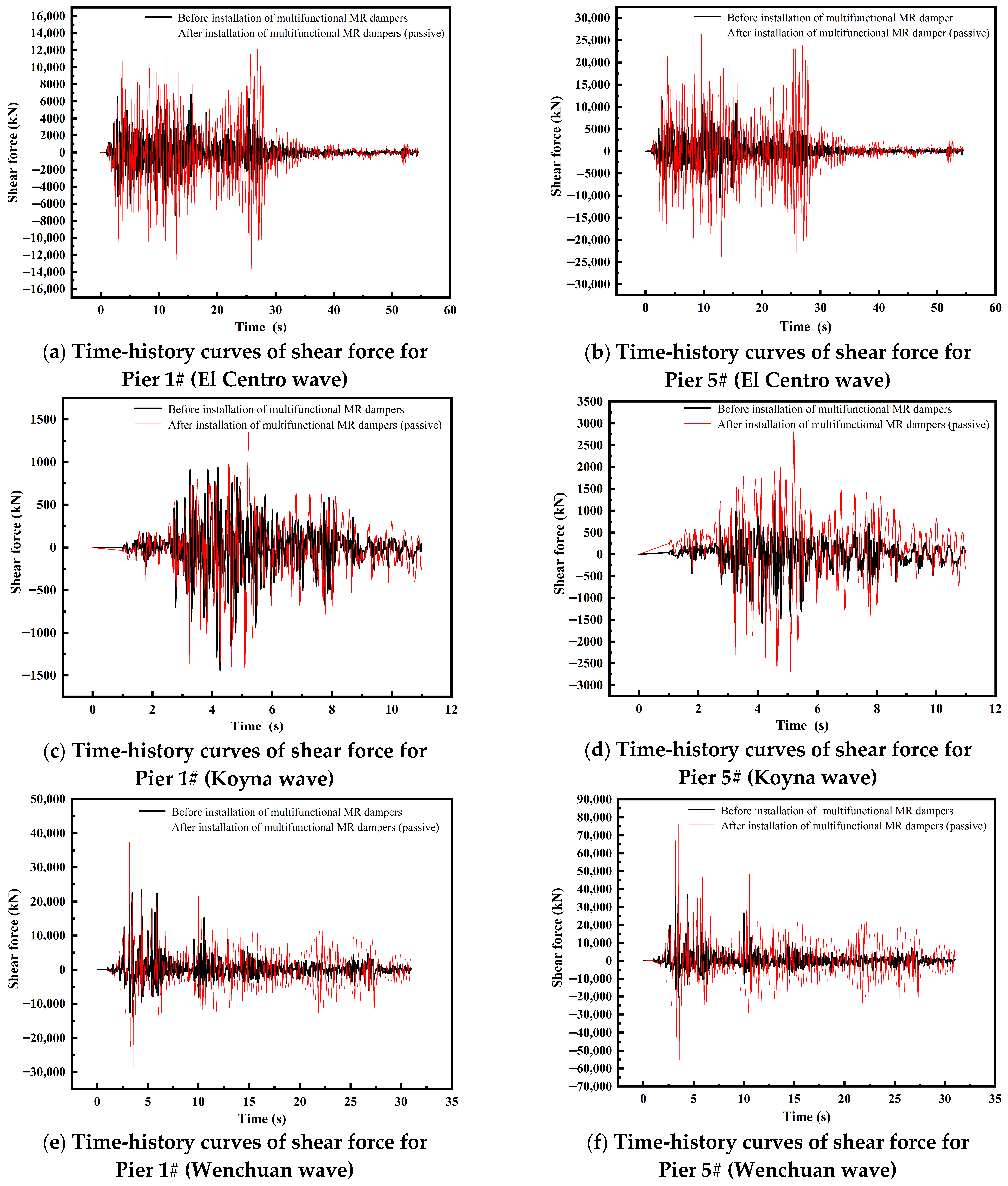
Conversely, under input ground motions from different seismic waves, all movable piers equipped with multifunctional MR dampers exhibit increases in internal force demand. Representative time-history curves of shear force for movable Piers 1# and 5# are shown in
Figure 10. These results clearly demonstrate that the multifunctional MR dampers successfully utilized their locking mechanism to distribute seismic loads (“load-sharing locking mechanism”). Specifically, the movable piers effectively share a portion of the seismic horizontal forces previously concentrated on the fixed pier. This behavior verifies the occurrence of internal force redistribution within the five-span continuous bridge structure.
Table 3 and
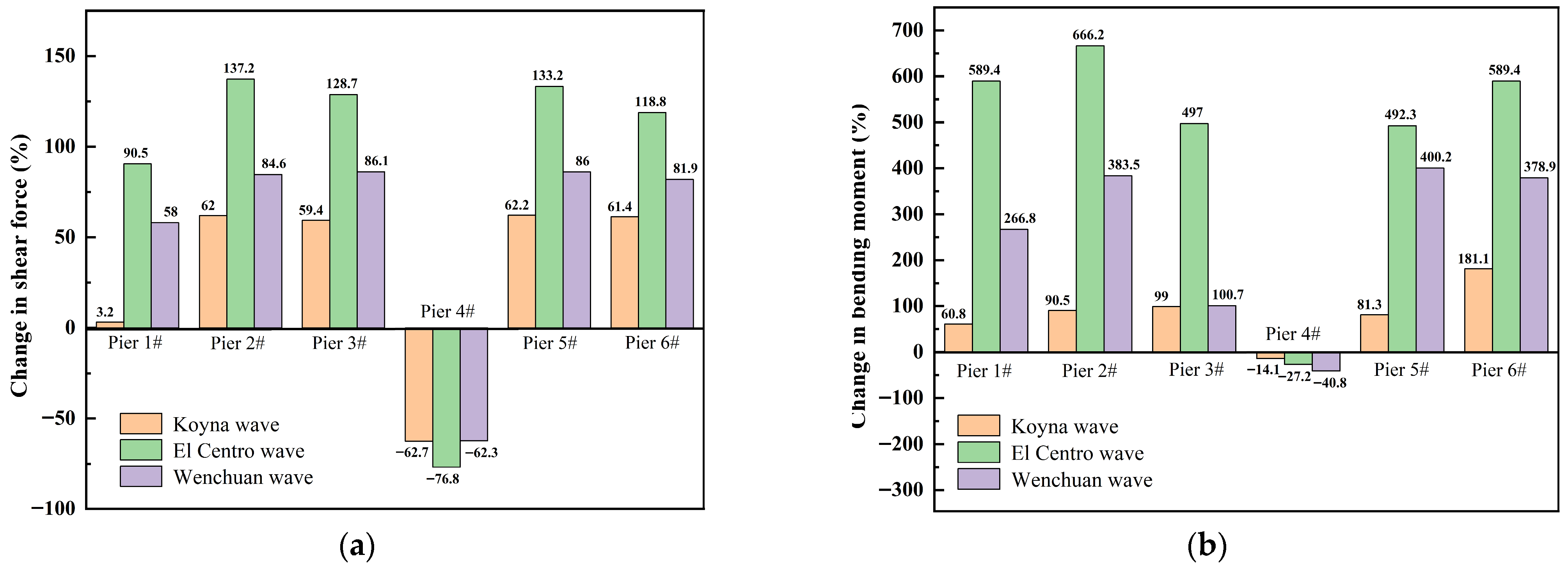
Table 4 present the maximum benchmark values and corresponding redistributed values of the longitudinal shear force and bending moment at the base of each pier in the five-span continuous bridge under the three input seismic waves. The redistribution effectiveness of multifunctional MR dampers is quantitatively demonstrated in
Figure 11a,b alongside
Table 3 and
Table 4. Without multifunctional MR dampers, Pier 4# (the fixed pier) bears most of the seismic horizontal force, while the movable piers bear minimal force. Upon installation of the multifunctional MR dampers, a significant portion of the seismic force originally concentrated on Pier 4# is redistributed to the movable piers. Crucially, movable piers experiencing higher seismic forces under the benchmark condition exhibit proportionally larger internal forces after redistribution. For instance, movable Pier 1#, being the farthest from the fixed pier, exhibits the smallest benchmark shear force and consequently experiences the smallest force increase post-redistribution. This indicates that the locking load-distribution mechanism of the multifunctional MR dampers is particularly effective for transferring forces to movable piers closer to the fixed pier, resulting in more substantial reductions in shear force and bending moment at Pier 4#. Furthermore, the magnitudes of internal forces (both benchmark and redistributed) correlate strongly with the Peak Ground Acceleration (PGA) of the input motions. Under the Koyna wave (which had the smallest PGA), all internal forces were minimized: the maximum shear force at Pier 4# decreased from 11,000 kN to 4098 kN (about a 62.7% reduction), and the maximum bending moment decreased from 32,696.9 kN·m to 28,071.5 kN·m (about a 14.1% reduction). In contrast, the Wenchuan wave (which had the largest PGA) produced the highest internal forces: Pier 4#’s maximum shear force was significantly reduced from 258,714 kN to 97,419 kN (about a 62.3% reduction), and its maximum bending moment substantially decreased from 706,853.0 kN·m to 418,546.0 kN·m (about a 40.8% reduction), demonstrating remarkably pronounced locking load-distribution effectiveness. Crucially, the rate-dependent locking function of the multifunctional MR dampers was fully activated under all three seismic inputs, irrespective of their distinct spectral bandwidths.
Critical response reductions were evaluated against the ASCE/SEI 41 and FEMA P58 thresholds. The 62.3% decrease in shear force at fixed Pier 4# under Wenchuan waves (
Table 3,
Figure 11a) reduces its demand-to-capacity ratio from 1.18 (pre-damper) to 0.44—below the 0.5 threshold for Immediate Occupancy (ASCE 41). Similarly, the 40.8% decrease in bending moment (
Table 4,
Figure 11b) transitions Pier 4#’s performance from Life Safety (pre-damper fragility probability: 72%) to Collapse Prevention (post-damper fragility probability: 93%) per FEMA P58. Conversely, the elevated forces at movable piers (e.g., Pier 2#: +666.2% bending moment under El Centro wave excitation) remain within the ductile design limits due to their structural redundancy, satisfying ASCE 41 for secondary components.
3.3. Semi-Active Vibration Control of the Multi-Span Bridge
The semi-step fixed-increment semi-active vibration control strategy not only achieves graded energy dissipation for multifunctional MR dampers under different seismic waves, but also overcomes the deficiencies of traditional fixed-increment semi-active control strategies [
41], demonstrating enhanced robustness. The underlying principle of on–off control involves adjusting the input energy to regulate structural vibrations [
42]. Consequently, this study proposes a semi-active fixed-increment on–off control strategy, formulated based on the design parameters of the multifunctional MR damper and its damping force curves. The core concept of this control strategy, leveraging the structural parameters of the multifunctional MR damper (notably, the decoupling spring’s maximum compression/maximum free stroke of 7 mm), is defined as follows: Under small displacements, when the structural displacement response and velocity response are directionally concordant (same sign), the multifunctional MR damper’s current controller activates, gradually increasing the control current by a fixed incremental coefficient
a to raise the damping force, which is capped at the device’s maximum achievable force; conversely, when the displacement response and velocity response are directionally discordant (opposite signs), the current controller deactivates. Under large displacements, the current control logic mirrors that of small displacements but employs a distinct fixed incremental coefficient
b. This strategy is governed by Equation (1),
where
Imax is the multifunctional MR damper’s maximum allowable control current;
I(
ti) and
I(
ti+1) represent the control currents at time steps
i and
i + 1, respectively; and
u(
t) and
denote the relative piston displacement and velocity. Equation (1) was implemented through an ABAQUS-Simulink co-simulation framework: ABAQUS solved structural dynamics while exporting real-time displacement
u(
t) and velocity
at damper nodes; Simulink executed Equation (1) to determine the control current
I(
ti+1) using displacement thresholds (∣
u(
t)∣ = 7 mm, based on
Section 2.3) and coefficients
a = 0.2/
b = 0.5 calibrated from experimental force–displacement curves (
Figure 4e,f). The current output was mapped to damping forces
F via cubic spline interpolation of the data from
Figure 4e,f, and then applied as concentrated nodal forces in ABAQUS with 0.001 s time-step synchronization.
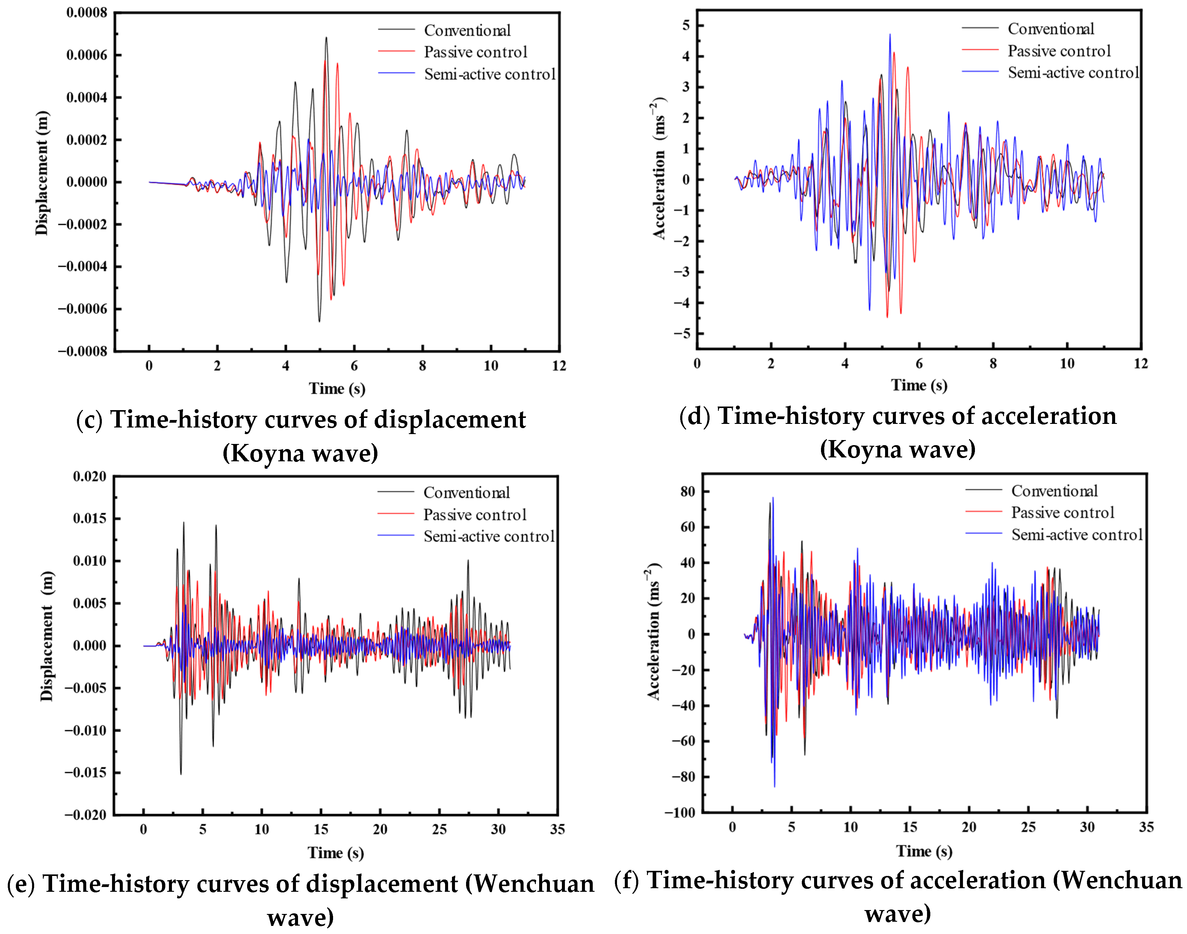
Figure 12 illustrates the vibration displacement and acceleration responses at the deck measurement point supported by Pier 4# (fixed pier) of the five-span continuous bridge under excitation from three seismic waves. Here, ‘Conventional’ denotes the scenario without multifunctional MR dampers on the movable piers; ‘Passive control’ indicates the vibration suppression effect with multifunctional MR dampers installed; and ‘Semi-active control’ represents the effect achieved using the proposed semi-step fixed-increment on–off control strategy. The results clearly indicate highly effective control of displacement responses at Pier 4# across all seismic inputs, whereas the control of acceleration responses was moderate. This occurs primarily because Pier 4# connects to the bridge deck via a fixed bearing, meaning the deck displacement measurement reflects pier movement directly. Furthermore, as multifunctional MR dampers primarily function as force-transferring and displacement-limiting components, acceleration transmission persists, resulting in accelerations at the pier–deck interface, while displacement response is effectively constrained.
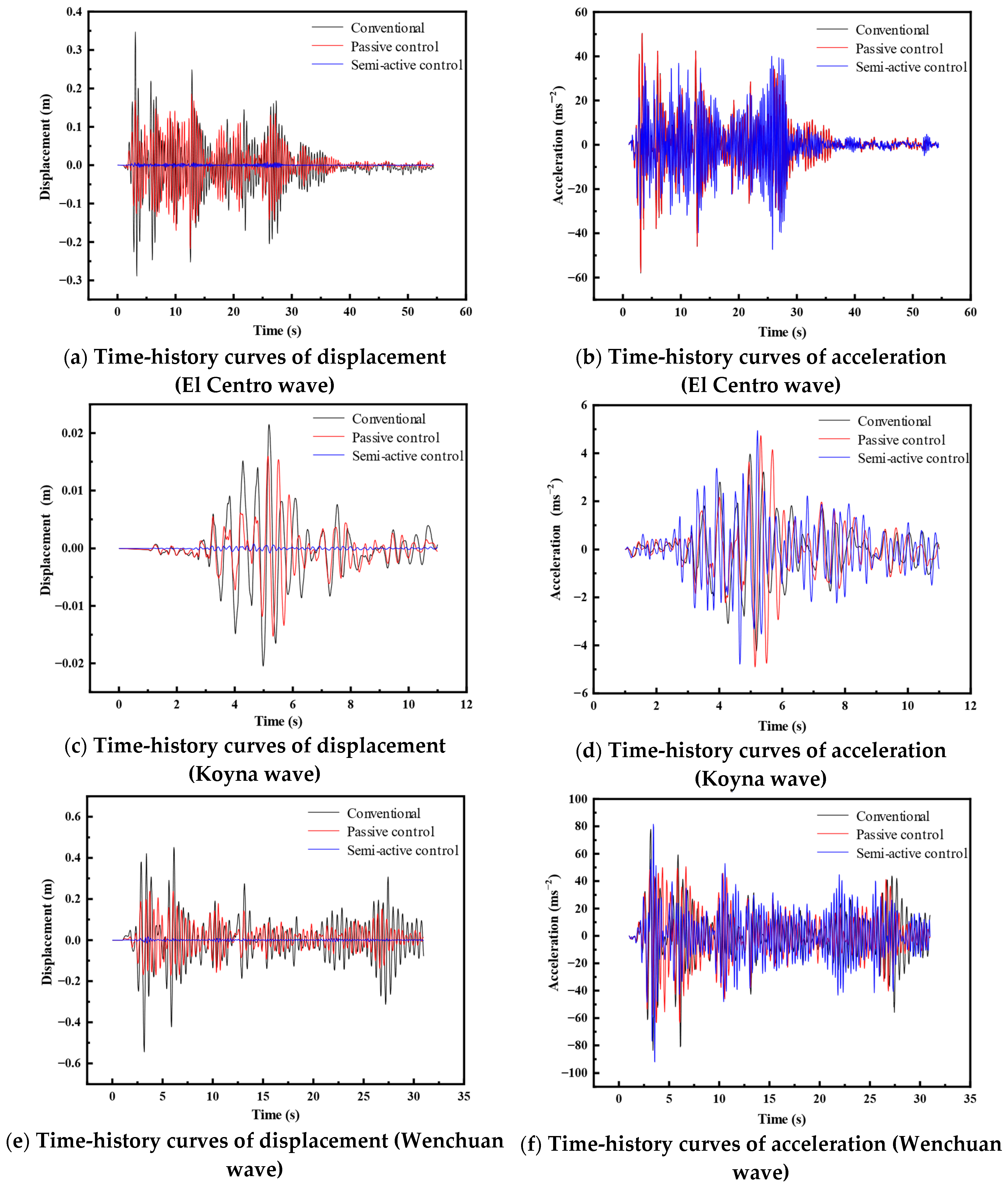
Figure 13 presents the displacement and acceleration responses at deck measurement points supported by the movable piers under the three seismic waves. Similarly, significant control of displacement responses is observed at all movable piers for various inputs, while acceleration control remains moderate. Crucially, movable piers connect to the deck via movable bearings that primarily resist vertical loads, transferring little or no horizontal load. Therefore, under conventional conditions (no multifunctional MR dampers), the pier head exhibits nearly negligible horizontal displacement, while its supported deck measurement point experiences relatively large displacements, comparable to those measured near the fixed pier. When employing multifunctional MR dampers for passive or semi-active control, the movable piers share the internal forces transmitted from the fixed pier. Consequently, acceleration transmission continues through the deck, yet the displacement response at the deck points supported by the movable piers is substantially reduced, clearly demonstrating effective control.
Table 5 presents the vibration control effectiveness at deck measurement points supported by each pier of the five-span continuous bridge under passive control (using multifunctional MR dampers) and semi-active control (employing the semi-step fixed-increment on–off strategy) for different seismic inputs. The data reveals that, while passive control with multifunctional MR dampers installed on movable piers achieves measurable displacement response reduction at all deck measurement points, semi-active control using the proposed strategy yields significant displacement suppression at points supported by movable piers, consistently exceeding 95%. For example, under El Centro wave excitation, displacement control effectiveness reaches 98.71% for movable Pier 1# and 77.27% for fixed Pier 4#. Furthermore, there are minor variations in displacement control effectiveness across seismic waves under semi-active control, generally demonstrating superior performance for El Centro, followed by Koyna, and then Wenchuan. Specifically, the control effectiveness at movable Pier 2# is 97.53% under the El Centro wave, 96.41% under the Koyna wave, and 96.14% under the Wenchuan wave.
Due to the force-transfer mechanism inherent in multifunctional MR dampers, passive control using these devices has limited effectiveness in suppressing acceleration responses at deck measurement points supported by the piers; in some cases, an amplification effect is observed. Under the high-intensity Wenchuan wave excitation, passive control achieves modest acceleration reduction across all piers, with the maximum effectiveness peaking at 37.99% for movable Pier 6#. However, passive control proves ineffective for mitigating acceleration under the other seismic inputs. Semi-active control using the semi-step fixed-increment on–off strategy provides measurable acceleration suppression under El Centro wave excitation, achieving its highest control effectiveness of 44.95% at movable Pier 6#. Consequently, multifunctional MR dampers primarily serve to control displacement responses in multi-span continuous bridges subjected to seismic events while demonstrating appreciable acceleration control effectiveness only under specific seismic wave excitations.
Figure 14 presents time-history curves of the internal forces for selected multifunctional MR dampers installed on the movable piers under Koyna wave excitation, comparing the responses during passive control and semi-active control using the semi-step fixed-increment on–off strategy. The results demonstrate that the internal forces generated within the multifunctional MR dampers under semi-active control are significantly greater than those observed during passive control under identical seismic excitation.
Unlike conventional MR dampers that solely rely on magnetic-field-controlled damping [
24,
26] or STF-based devices limited to passive stiffening [
38], our multifunctional MR damper uniquely integrates both mechanisms to address the full spectrum of seismic challenges. The high-frequency load-sharing locking mechanism redistributes forces before structural damage initiates, while the low-frequency magnetically controlled damping adaptively suppresses resonant vibrations—synergies unattainable in the proposed damper’s single-mode counterparts. This dual functionality transcends existing solutions by simultaneously optimizing force redistribution and displacement control, offering a scalable strategy for long-span bridges, building isolation systems, and other vibration-sensitive infrastructure where multi-hazard resilience is paramount.


