Abstract
The frame of a quadcopter drone is the most important component, as it supports all other systems and plays a vital structural role, supporting the stresses that appear during flight. The objective was to reduce the weight of the frame (18% reduction compared to the original version manufactured from carbon fibre), while maintaining structural integrity, by using an integrated strategy that includes optimizing the frame shape according to the components used, the stresses it must withstand, and considerations related to design for additive manufacturing. The optimization of the quadcopter drone frame was achieved using generative design and additive technologies (3D printing) and represents a cutting-edge approach in aerospace engineering, which allows for overcoming the limitations of traditional manufacturing methods. This study successfully completed all stages of the aeronautical product development cycle, from preliminary design, generative design, structural analysis, and 3D printing to assembly and functionality testing. The integration of generative design and 3D printing into the aeronautical product development cycle represents a complex and feasible challenge, with advantages in terms of efficiency, performance, and innovation capacity that fully justify the effort.
1. Introduction
Topology optimization [1,2] and generative design [3] are modern techniques used in the life cycle of aerospace products with the aim of reducing manufacturing costs and weight, but also improving product performance. Topology optimization assists in the development of new products by providing a series of virtual iterations, calculating an optimal conceptual design based on a finite element model that satisfies a functional optimization objective, a set of geometric constraints, or a range of manufacturing requirements [4,5,6]. Topology optimization is a tool widely used by engineers, with applications in various fields: aerospace [7,8], automotive [9,10,11], architecture [12,13], and biomedical engineering [14,15].
Generative design is a computational design technique that can automatically study a design with various constraints defined by mechanical engineers. Generative models based on topology optimization use algorithms based on artificial intelligence and generate various topology models that cannot be represented by classical parametric design approaches [16,17]. Generative design is a modern technique with recent applications in engineering (aviation, manufacturing, automotive, and construction) that uses mathematical principles and generative algorithms based on artificial intelligence, leading to a synergy between architecture, unique and innovative design, and information technology [18,19,20].
Generative design tools combine human creativity with artificial intelligence to generate numerous design models in parallel with cloud computing that meet predefined criteria based on the user’s initial requirements, such as materials used, design environment and functional surfaces, performance requirements, and manufacturing constraints [18,20,21]. Generative design and additive technologies are closely linked, enabling CAD (Computer-Aided Design) models to be produced physically in the shortest possible time and at low cost. Additive manufacturing processes offer unlimited possibilities for creating innovative and customized products using various types of materials: composites, metals, and polymers.
Table 1 provides an overview of the key materials, advantages and disadvantages, and specific applications of the primary additive manufacturing processes.

Table 1.
Comparative analysis of additive manufacturing processes [22,23,24,25].
Additive manufacturing processes for drone components [26,27] have developed in the UAV industry, offering numerous advantages in terms of customization, topological optimization, material testing, and rapid prototyping [28,29,30]. A recent study [31] addresses a generative software tool that can help create aircraft or UAV (Unmanned Aerial Vehicles) models in CAD software systems based on parametric models, aircraft model databases, preliminary design methods, and technological and aerodynamic requirements.
Topological optimization and additive technologies have become essential tools in the design, manufacture, and testing of aircraft structures (UAVs, airplanes, helicopters, gliders, and satellites). These technologies make it possible to produce lighter, stiffer, and more efficient components, which is crucial in the aerospace industry [32,33,34]. A heavily researched area of topological optimization in the aerospace field is brackets. Brackets are vital mechanical components used to fix and secure the position of other parts or assemblies, with applications in the aerospace industry [35,36]. Topological optimization of brackets manufactured by selective laser melting (SLM) is an advanced engineering approach that combines the benefits of generative design with the production capabilities of SLM technology. The success of a topologically optimized part manufactured through selective laser melting (SLM) is evaluated using three essential categories of metrics: mechanical and material properties, geometric accuracy and quality, and economic and process metrics. The SLM manufacturing process results in a customized bracket adapted to the specific requirements of each application and with low production costs [37,38,39].
Generative design is an innovative technique for obtaining and developing drone frames, representing an approach based on algorithms and artificial intelligence for the structural optimization of aviation parts [40]. In this way, drone models can have complex and efficient designs that would be difficult or impossible to achieve using traditional design methods [41]. An interesting approach to the use of generative design and additive manufacturing in the creation of a drone frame with the aim of improving the strength-to-weight and power-to-weight ratios for precision agricultural applications was taken by Balayan et al. [42]. Another study [43] explored the implementation of generative design in the manufacture of UAV frames, using the FFF (Fused Filament Fabrication) process and carbon fibre-reinforced nylon (PolyMideTM PA6-CF) filament. Following the 35 feasible solutions generated for the drone frame, as well as finite element analyses and experimental tests, minimum displacement (0.12 mm) was determined under a load of 1.4 kg, and the equivalent von Mises stress was 3.28 MPa, along with a significant weight reduction of 66.28% compared to the original model [43]. The frame of the DJI F450 quadcopter drone was redesigned using generative design in the Autodesk Fusion software system, and the FEA (Finite Elements Analysis) results indicated a lower displacement compared to the initial DJI F450 drone frame [44]. Generative design was used to generate a series of models for a cargo drone, and the final model generated had the following constraints: maximum structural efficiency, manufacturability using additive technologies, operational safety, and good functionality [45].
Based on the current stage, it can be stated that a series of studies have been conducted in the field of generative design applied to drones or components of drone structures. However, very few studies have completed the entire cycle of drone development, from design to final assembly/initial operational testing. The objective of this paper is to demonstrate the feasibility of manufacturing a quadcopter drone using additive manufacturing and generative design processes, integrating all stages of UAV system development, starting from preliminary design, generative design, finite element analysis, and 3D printing, through to component assembly and functional testing.
2. Preliminary Design and Selection of Drone Components
The preliminary design for a quadrotor drone covers the important aspects necessary to begin the process of designing, developing, and building the drone. Specific details are refined during the generative design stage, depending on the specific requirements and constraints of the drone. Figure 1 describes the main stages of the preliminary design of the drone.

Figure 1.
Flowchart of the preliminary design process of quadcopter drone [46].
The main goal of this study is to design a racing drone that is optimized for agility and high manoeuvrability, allowing it to perform the following missions: entertainment and sports; dynamic video capture using a GoPro camera; and improving piloting skills and exploring flight limits. The drone developed in this paper is classified as C1 (according to the European Union Aviation Safety Agency—EASA), with a maximum take-off weight of 900 g, a maximum flight altitude of 120 m, and a maximum horizontal flight speed limited to 19 m/s [47]. The target mass from the generative design for the drone developed in this study is 750 g. The thrust-to-weight ratio (T/W) is a crucial factor in the flight performance of a drone, being the total thrust generated by the drone’s motors and propellers and the total weight of the drone. Since the main goal is to develop a racing drone, which requires a very high T/W ratio, usually between 5:1 and up to 10:1, for fast acceleration and sudden manoeuvres, the appropriate thrust-to-weight ratio is 9:1. To select the motor, the thrust per motor indicator was determined using Equation (1) [42].
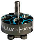
Based on the maximum motor thrust achieved, the HQProp FLUX motor (pull = 1676 g) was chosen, which does not exceed the thrust required for racing drones (1687 g), thus maintaining a high thrust-to-weight ratio (9.5:1). A stack that incorporates the FC (Flight Controller) and ESC (Electronic Speed Controllers) is a good option because it simplifies installation and reduces the risk of compatibility issues between the two components. Thus, the Mamba Stack with an MCU (Microcontroller Unit) was chosen, which can reach frequencies of up to 216 MHz. These MCUs are popular in-flight controllers because they offer a balance between performance and cost. Analysing the motor performance provided by the manufacturer, it was found that the tests were performed on standard 5-inch diameter propellers. Therefore, Foxeer Donut 5145 propellers, which have a diameter of 5 inches and two blades, which determine efficiency and high speed, were chosen for the model drone.
The selection of the drone battery was made in close connection with the characteristics of the motors, as they are the main consumers of energy, and their performance depends directly on the power supply. Considering the drone’s motors, a lithium-polymer battery with a capacity of 1550 mAh, voltage of 22.2 V, high discharge rate (120 C), and a good balance between power and low weight was used. A 22.2 V battery was chosen so that the motor-propeller assembly generates sufficient power, which is a good choice for a racing drone. The flight time of a racing drone is generally short, as they are designed for speed and agility, which require high energy consumption. The drone’s autonomy is calculated based on the motor and battery data, using Equation (2).
Table 2 shows the drone’s autonomy based on throttle level and current consumption.

Table 2.
Determining the flight time of drone based on throttle level [48].
In a flight scenario, it is easy to calculate the flight time in mixed mode using the following flight time distribution: 100% throttle–5% of flight time; 75% throttle–5% of flight time; 50% throttle–20% of flight time; 25% throttle–70% of flight time. Using the percentages established for this flight scenario and knowing the average current consumption, the autonomy of the drone in mixed mode is 3 min and 46 s. Of course, the autonomy of the drone varies depending on the flight mode and how much power is required to keep the drone in the air and perform manoeuvres. The last activity in Figure 1, the generative design of the drone frame, will be presented in detail in Section 3. Based on the preliminary design and the mission of the drone, the main components used in the development of the drone were established (Table 3).

Table 3.
Components necessary for assembling the drone model.
3. Generative Design of the Quadcopter Drone Frame
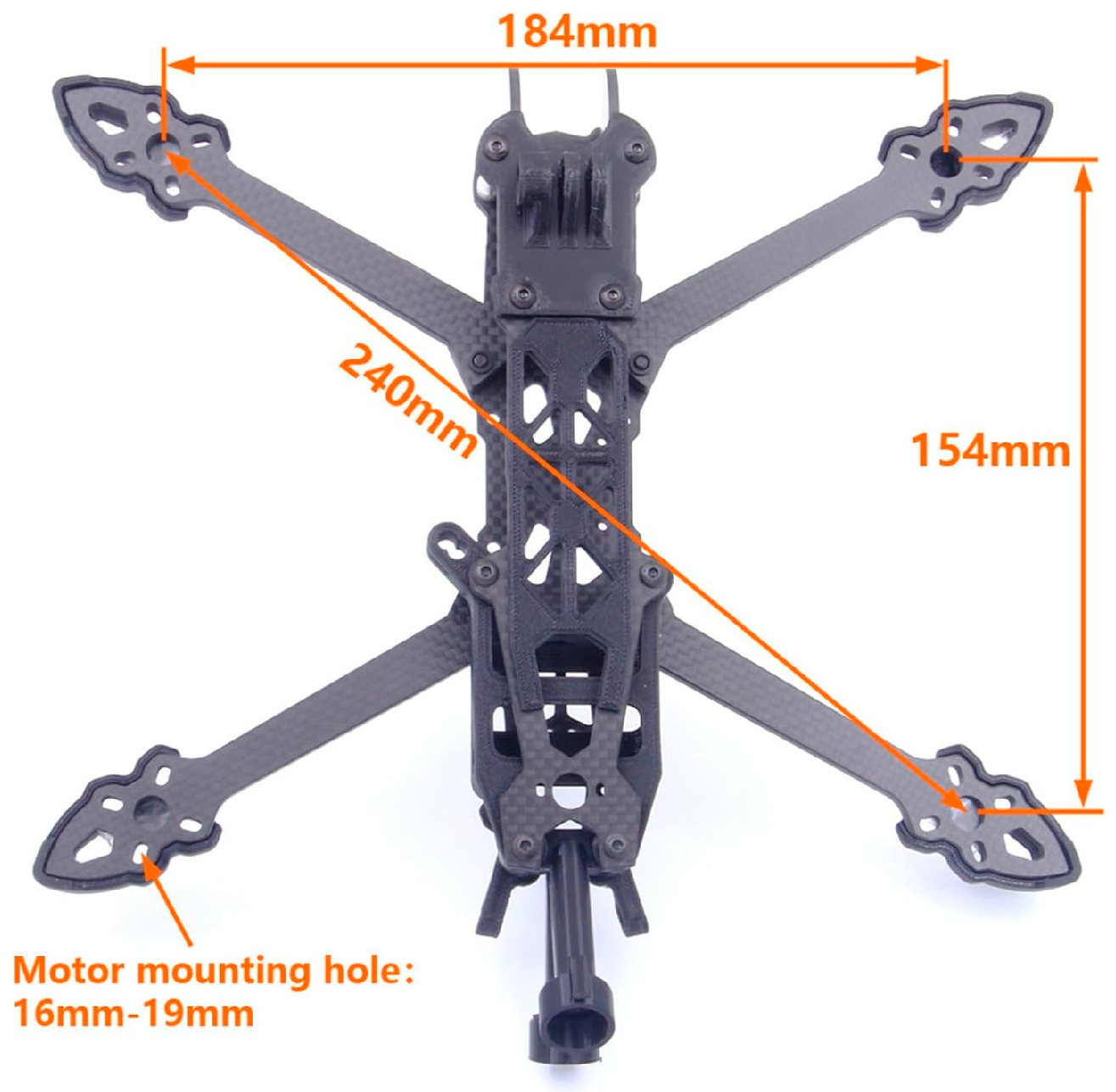
For this study, the reference parameters were provided by the Mark4 HD drone [58] made of carbon fibre, weighing 163 g and measured as shown in Figure 2.
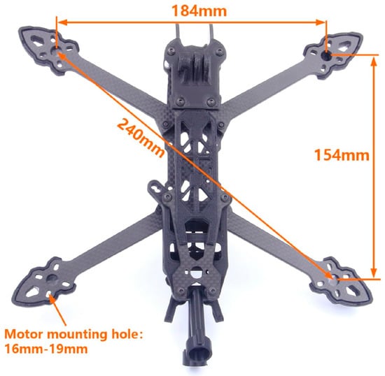
Figure 2.
Reference drone frame [58].
The Autodesk Fusion 360 software system (Autodesk, 2023) was used for the generative design process of the drone frame. The main stages of the generative design process are described in Figure 3.

Figure 3.
Workflow specific to the generative design process using the Autodesk Fusion 360 software system [42,59,60].
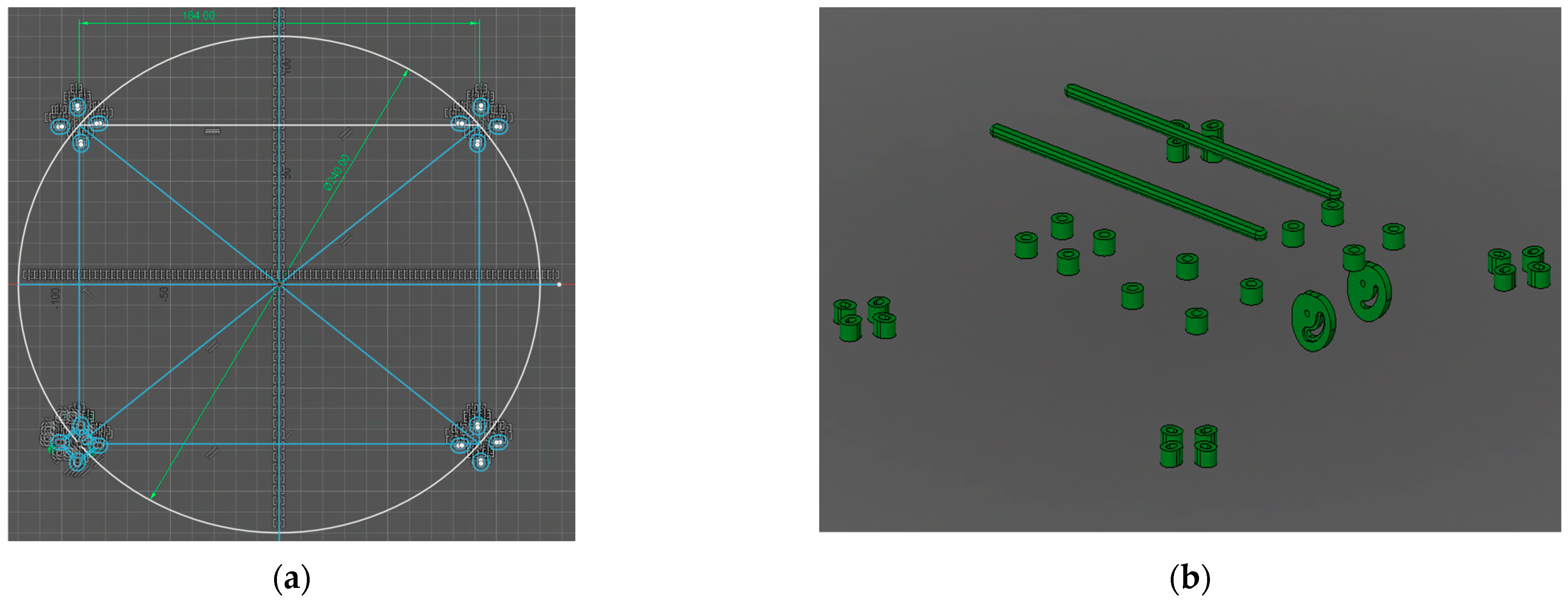
To establish the initial parameters of the generative design, the dimensions of the drone frame in Figure 2 were taken, and the dimensions of the new frame were defined as follows: motor layout at a diagonal distance of 240 mm; width of 184 mm (Figure 4a). Preserved geometry refers to those areas of the 3D model that cannot be modified by generative design. These preserved areas are divided into four categories (Figure 4b): through holes for mounting the GoPro camera mount and electronic components such as the flight controller, electronic speed controllers, and video transmitter; through holes for mounting the electric motors; mounts and holes for the first-person view (FPV) camera; and rail-type supports (length 130 mm) for the battery, designed to allow the battery to be moved front to back, thereby changing the centre of gravity of the drone. The battery will be positioned above the drone electronics for easy access and quick installation and removal. Obstacle geometry is represented by those objects or shapes necessary to restrict the AI-assisted generative design software so that it cannot create material structures in those areas. In this study, these obstacle geometries were divided as follows: obstacles to the electronics placed in the central area of the drone frame structure; obstacles for the passage holes and for maintaining the shape of certain required geometries; obstacles created by motors and the space required for propellers; and other necessary obstacles created during the modelling/generation process of the drone frame.
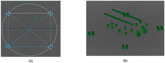
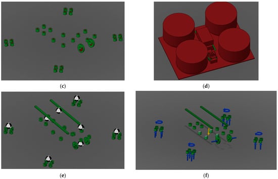
Figure 4.
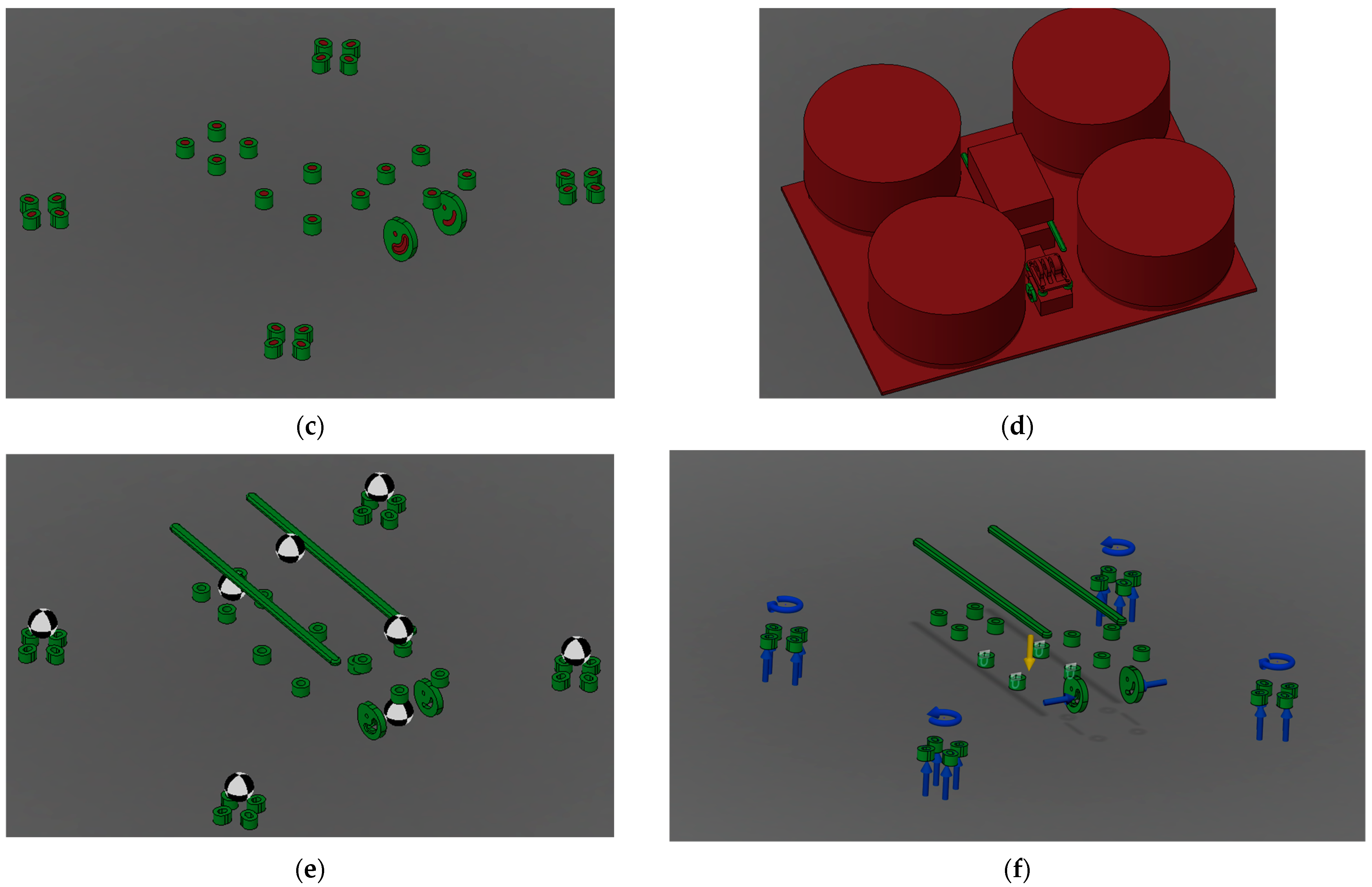
Stages of the generative design process applied to the drone frame: (a) initial sketch; (b) preserved geometry assembly; (c) obstacle clearance holes; (d) final obstacle geometry of drone frame; (e); arrangement of centres of gravity; (f) constraints and forces applied to the drone structure.
At the rear of the frame is the space required for the video transmitter, with the central space reserved for the FC and ESC. At the front is the space between the two geometries reserved for mounting the FPV camera. Between them are the obstacles for the cable passage and access to components. Above them, supported by the four mounting slots, is the GoPro camera mount, and further back is the obstacle created for the battery, which is supported by the rails of the required geometry. The positioning of these obstacles is strategic, ensuring easy access for the subsequent assembly of components. The obstacles for the through holes can be seen in Figure 4c. These obstacles were created so that the generative design does not fill the holes needed to mount the motors, electronic components, GoPro mount, and FPV camera, as this would complicate the assembly stages and render the generated frame unusable. To create obstacles, the dimensions of the propeller and electric motor were taken into account in the rotor area of the drone. The drone will be powered by four HQProp FLUX 2207 motors [48], with a motor diameter of 28.3 mm and a length of 32.2 mm, and a Foxeer Donut 5145 toroidal propeller’s diameter [49] is 130 mm. The geometry and final layout of the obstacles can be seen in Figure 4d. The obstacle created as a plate shape (Figure 4d) is located under the mounting locations of the motors and electronics in the central part of the drone. It was added after the first iterative generation because in the initial design the structure would have passed through the lower part, which would have made it impossible to position the drone on the ground or land in a stable and safe manner.
Defining parameters refers to all requirements, limitations, and tasks that were established before the actual start of the design generation, as well as the objectives proposed in this iterative study, for example, the minimum safety factor and target mass of the final frame. Using a safety factor of 2 for a drone frame manufactured using 3D printing is a prudent measure; a safety factor of 1.5 is commonly used in aerospace design. This higher safety factor contributes to increased structural safety of the drone, as it compensates for the disadvantages associated with material extrusion processes, such as material voids and anisotropy of the extruded material. It should be noted that these parameters are variable, and their values represent baseline values in model generation, with the software system optimizing the final result. The parameters that formed the basis for the generative design of the drone frame are shown in Table 4.

Table 4.
Main parameters established in the generative design process of the frame.
Figure 4e shows the centres of gravity of the components (Table 3) to be mounted on the drone frame, as follows: the motors are positioned centrally relative to the corresponding mounting holes, the electronic components and the GoPro camera are similarly positioned, and the battery has its centre of gravity positioned symmetrically between the support rails and centrally between the front and rear.
The last step before generating the design is to apply the constraints and demands that the frame must withstand (Figure 4f). The main constraint (fixed support) is on the four mounting areas of the FC and ESC, as that area must not deform during flight for the accelerometer and electronic gyroscope to function correctly, thus stabilizing the drone. The loads applied to the drone frame were as follows: thrust force of 20 N for each rotor (1676 g ≅ 16.43 N–pull throttle 100% of the motor technical data multiplied by a safety factor [61,62] of 1.2); weight force–7.3 N (summing the mass of all components approximately as 750 g multiplied by gravitational acceleration); the moment per rotor 0.2 N∙m was determined using Equation (3) [42]; the compression force of the FPV camera was 2 N.
A comparative analysis (Table 5) of materials is essential for choosing the best option for a generatively designed drone frame, as the properties of each material (PLA, Tough PLA, and Acrylonitrile Butadiene Styrene—ABS) directly influence the performance, durability, and ease of manufacturing of the final part.

Table 5.
Analysis of materials used for additive manufacturing of the drone frame [63,64,65].
After analysis of the three materials (Table 5) used in additive manufacturing, Tough PLA was the best choice for the prototype frame of the quadcopter drone. Tough PLA offers the optimal balance between ease of 3D printing and mechanical performance, with no delamination or warping during the printing process. It also provides the rigidity necessary for stable flight, while offering the impact resistance needed to survive minor accidents, making it a more reliable option than standard PLA material, without the 3D printing challenges of ABS (warping, layer delamination, temperature sensitivity, and toxic emissions).
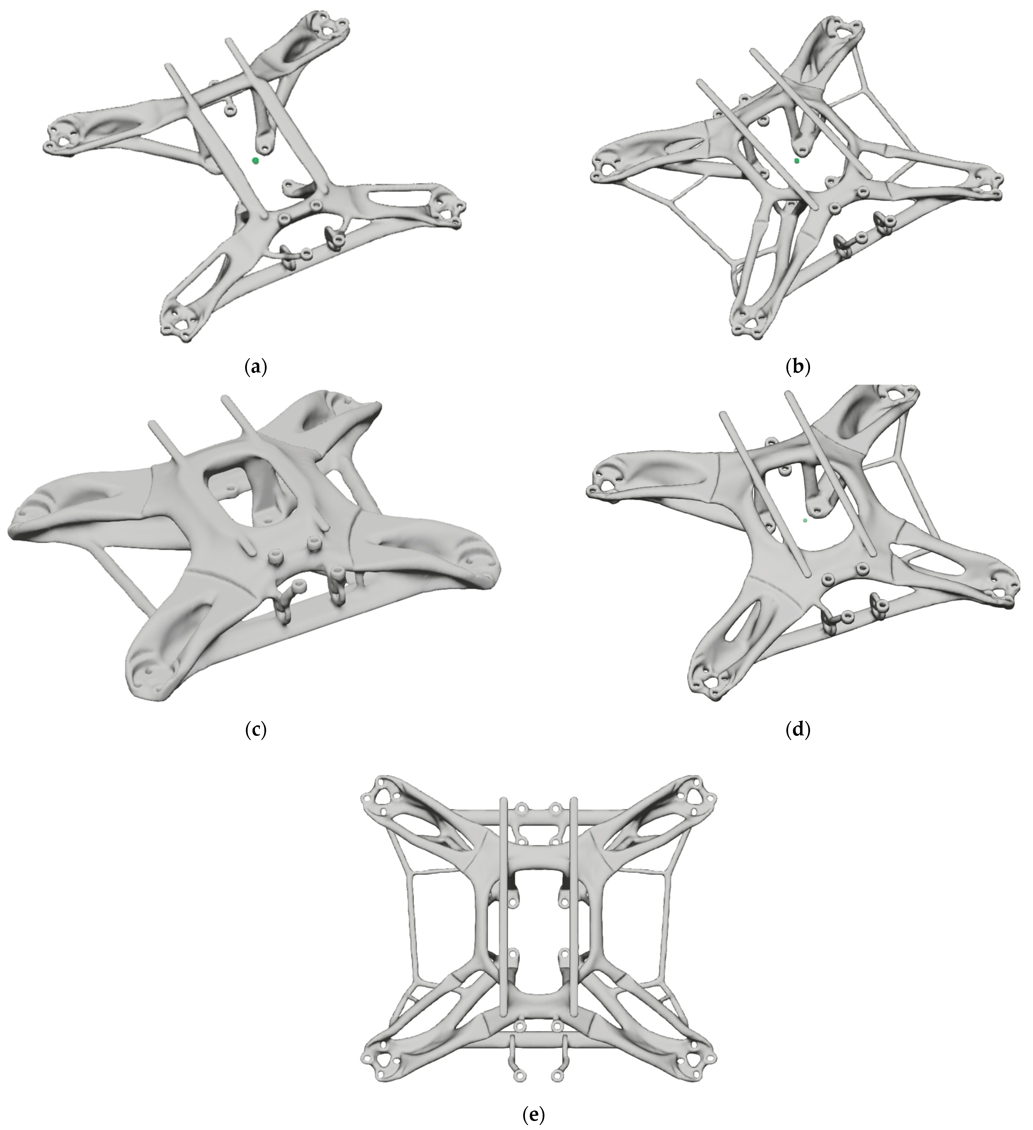
Obtaining solutions generated by generative design varies depending on the requirements and constraints imposed, with 13 different outcomes generated to observe the drone frames generated by the iteration method. Some of the outcomes have lower safety factors and obviously a minimization of the drone frame mass (Model 1—Figure 5a and Model 2—Figure 5b), while other outcomes have a defined target mass and the main goal of maximizing stiffness (Model 3—Figure 5c, Model 4—Figure 5d, Model 5—Figure 5e). Examples of outcomes generated by generative design based on the main parameters (Table 4) are described in Figure 5.
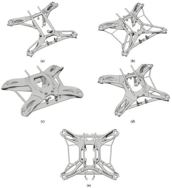
Figure 5.
Outcomes achieved through generative design on the quadcopter drone frame: (a) and (b) results achieved by reducing mass; (c–e) results achieved by stiffening the drone frame structure.
The following factors were considered when selecting the final drone frame design:
- Final weight–a lighter drone frame means greater flight autonomy and higher manoeuvrability;
- Structural strength–the drone frame must be sufficiently rigid so as not to deform under flight loads and have high structural performance to support the components (motors, battery, and flight controller) and withstand possible minor accidents. Also, the maximum stress appearing in the frame simulation must not exceed the maximum strength of the material from which the drone is made;
- Manufacturing method–generative design is often optimized for additive manufacturing. At this stage, the 3D printing method for the drone frame, areas with difficulties in 3D printing, and the creation of supports and their removal method were analysed and simulated (using the Ultimaker Cura 5.1.1 additive manufacturing preparation software system);
- Space and integration of drone components—the frame must provide adequate space and secure mounting points for all essential drone components (motors, propellers, battery, flight controller, and camera).
A multi-criteria analysis of the five most representative solutions for the drone frame (from Figure 5) is presented in Table 6. Thus, for the five models generated (Figure 5), a score was assigned based on their performance for each criterion, on a scale from 1 to 10 (1 = very poor, 10 = excellent).

Table 6.
Multi-criteria analysis of the five drone frame models created using generative design.
After studying the models performed by generative design, using a multi-criteria analysis (Table 6), the generative model with the highest final score (model 5—Figure 5e) was selected. Thus, a balanced solution was chosen that maximizes overall performance in relation to the design priorities and constraints, rather than excelling in a single criterion.
4. Simulation Analysis of the Drone Frame
Finite element analysis (FEA) in static analysis on the quadcopter frame is an important step in validating and understanding the structural behaviour of the component prior to manufacturing and physical realization. This finite element analysis was performed to verify that the generative design model will withstand the loads under actual operating conditions.
4.1. Static Analysis of the Drone Frame
For the finite element analysis of the drone frame model, the ANSYS software 2021 R2 (Canonsburg, PA, USA) Static Structural Module was used. In several studies [66,67,68], 3D-printed materials produced using the FFF process have been considered orthotropic materials. For the FEA simulation in this study, Tough PLA material was considered orthotropic and presented the following properties (Table 7).

Table 7.
Orthotropic properties of Tough PLA material used in FEA simulation [64,69,70].
Based on the mesh convergence analysis, a 1 mm element size was adopted to create a drone frame model comprising 348,368 nodes and 194,446 SOLID 187 tetrahedral elements (Figure 6a). To evaluate the static performance of the drone frame, the following boundary conditions were imposed: the frame was fixed to the surface at the four mounting holes for the FC and ESC and to the battery mounting area (Figure 6b).


Figure 6.
The main stages of finite element analysis of the drone frame: (a) generating the mesh of the drone frame; (b) establishing boundary conditions and loads; (c) distribution of equivalent stresses; (d) distribution of total displacements.
The following loads were applied: a pull force of 20 N was applied to the end of each arm in the area where the motor was mounted; a weight force of 7.3 N was applied to the central surface of the drone frame; and a moment of 0.2 N·m was applied to the surface where the motor was mounted (Figure 6b).
As can be seen in Figure 6c, the equivalent stresses with the highest values are found in the four mounting areas of the FC and ESC, where the model was also fixed. High stresses were also reported in the area between the central section and the battery mounting rails. With an equivalent stress of 2.5 MPa, the frame can withstand the operating stresses of a racing quadcopter drone. However, given that the safety factor is high, at 17, it can be evidenced that the model also could have been 3D printed with an infill density of approximately 50% to reduce weight. The maximum total displacement of 0.14 mm is small (Figure 6d) and occurs at the ends of the arms (in the motor mounting area), but does not affect the structural integrity of the drone.
4.2. Modal Analysis of the Drone Frame
The principal objective of modal analysis is to determine modal parameters, providing a solid basis for evaluating structural system vibrations, diagnosing defects, and optimizing dynamic design [71,72]. For this study, the ANSYS Workbench software system (2021 R2) was used to analyse the quadcopter drone frame. The drone frame was discretized with a mesh size of 1 mm, with 348,368 nodes and 194,446 SOLID187 tetrahedral elements. Considering the operating conditions of the quadcopter drone, an unconstrained free mode analysis was performed.
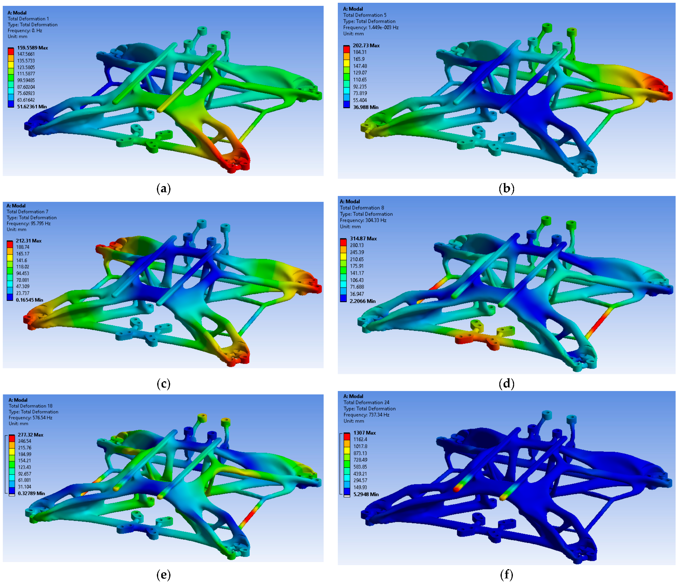
A modal analysis of an unconstrained drone frame, without any restrictions, is an essential phase in structural engineering and provides fundamental information about the intrinsic behaviour of the analysed structure. As can be seen in Figure 7a,b, the first six vibration modes of the drone frame obtained have a frequency of 0 Hz or very low (in the case of modes 4, 5, and 6) and represent the translational motion on the three axes (X, Y, and Z) and the rotation around the same axes of a rigid body.
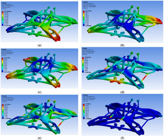
Figure 7.
The mode shapes and natural frequencies of the quadcopter drone frame: (a) mode 1; (b) mode 5; (c) mode 7; (d) mode 8; (e) mode 18; (f) mode 24.
Figure 7c–e, and f show the 18 subsequent modes, which describe the vibration characteristics of the drone frame structure. The modal analysis results show that the main areas of vibrational deformation are in the motor mounting zone and at the junction between the arms and the main part of the drone frame.
The first vibration modes correspond to vertical bending loads on the drone’s frame arms (mode 7, Figure 7c), with an initial frequency of 95.7 Hz. Subsequently, vibration modes involving a combination of vertical bending and horizontal torsion of the arms, as well as the rods connecting the arms and the accumulator rods, appear (Figure 7d–f). The values of these modes vary between 304.3 Hz and 737.3 Hz. To prevent damage to the drone, it is crucial that the operating frequency of the motors does not coincide with the frame prototype’s natural frequency. To verify the operating frequency of the HQProp FLUX 2207 motors used on the drone, the motor speed was determined in rotations per minute (rpm) using Equation (4). Therefore, the speed of the HQProp FLUX 2207 brushless motor is 43,956 RPM.
Equation (5) was used to calculate the operating frequency of the HQProp FLUX 2207 motor. This type of motor has seven magnetic pole pairs (P), and the calculated frequency is 5128 Hz.
The operating frequency of the motor (5128 Hz) is much higher than the maximum natural frequency of the drone frame, as determined by FEA modal analysis (737.3 Hz). Therefore, resonance should not be a problem for the drone frame obtained through generative design in this scenario. The significant difference in frequency ensures that the vibrations generated by the motors will not amplify to a dangerous degree and cause resonance. In conclusion, the modal analysis of the drone frame demonstrated that there are no natural frequencies within the motors’ operating range. Therefore, no problems that could compromise the control or position of the drone are expected to arise from this point of view.
5. Additive Manufacturing of Drone Frame
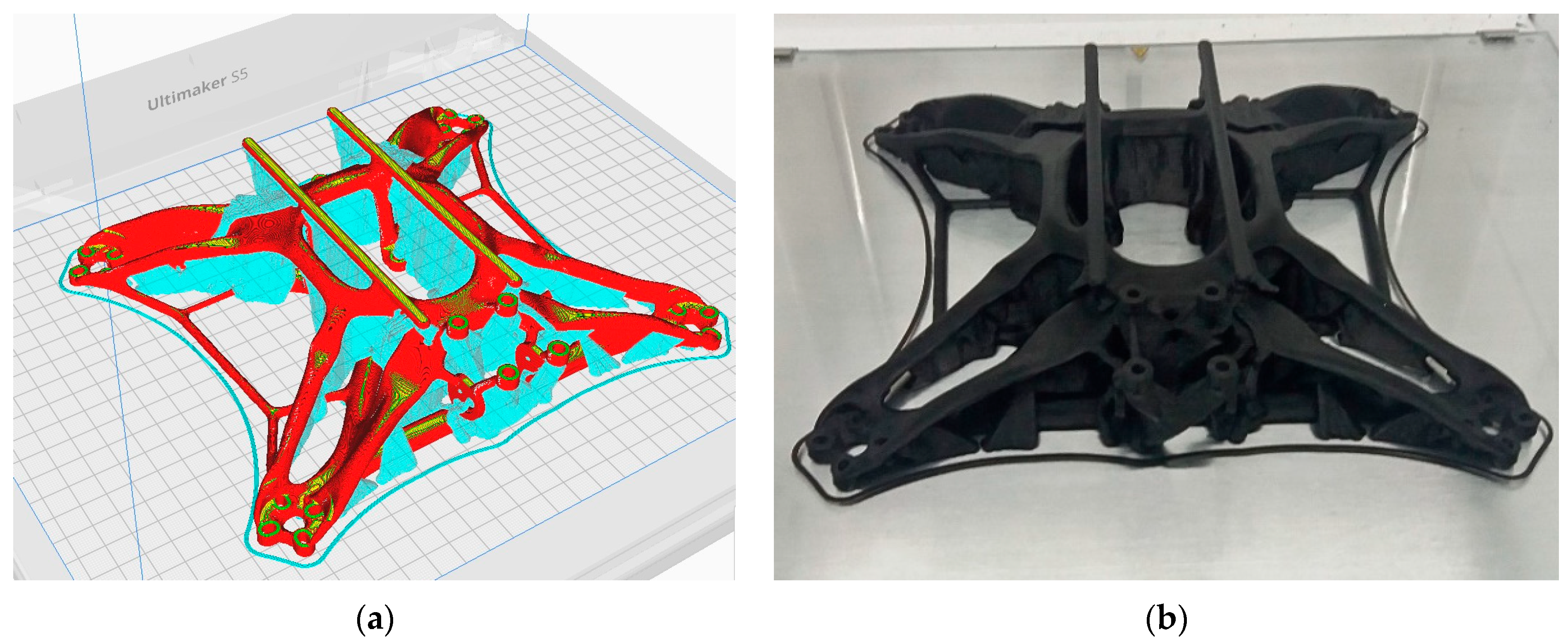
The drone frame, obtained using generative design in the Autodesk Fusion software system, was manufactured using the FFF process with an Ultimaker S5 printer and Tough PLA filament. Preparation for additive manufacturing was carried out using the Ultimaker Cura software system, and the total printing time was 42 h and 25 min, with the mass of Tough PLA filament used being 192 g (Figure 8a). Of course, this filament mass is the total mass, which also includes the support required for the additive manufacturing of the drone frame, and the drone frame has a mass of 135 g (Figure 8b).
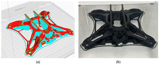
Figure 8.
Drone frame manufacturing: (a) preparing the drone frame for manufacturing; (b) 3D-printed quadcopter drone frame.
Setting the 3D printing parameters (Table 8) for the drone frame is an important step because it guarantees a structure that achieves the ideal balance between structural strength, minimal weight, and superior surface quality.

Table 8.
FFF process parameters for manufacturing the drone frame.
6. Assembling Components and Verifying Drone Operation
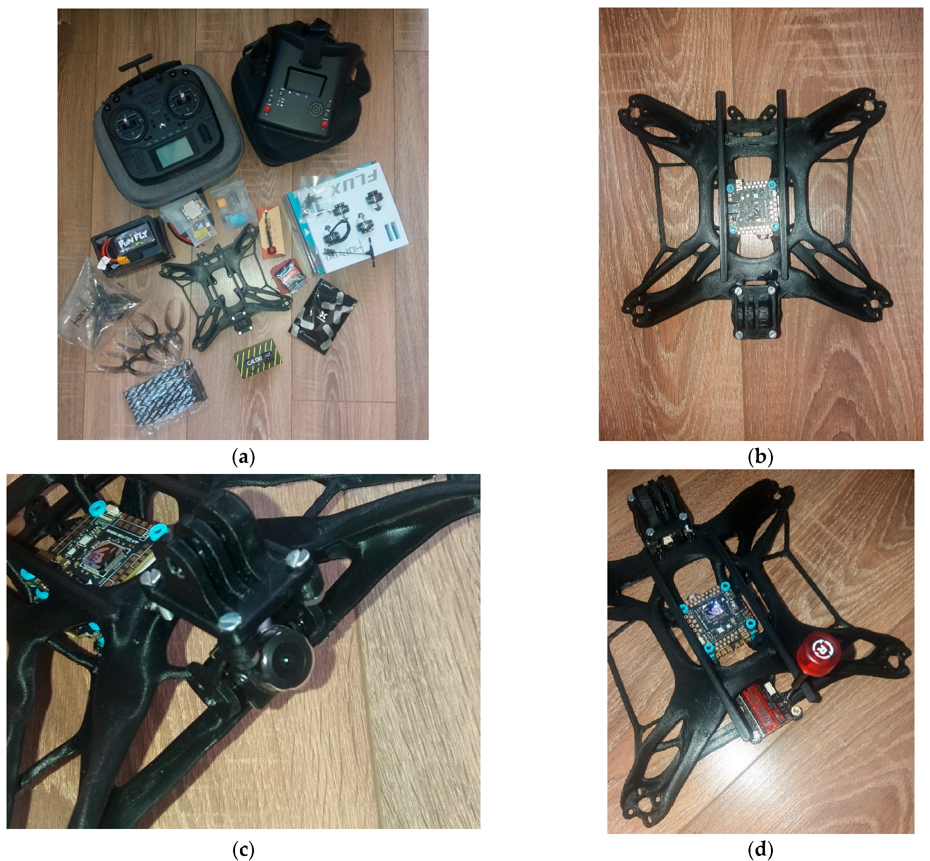
This section outlines the assembly steps and key component specifications. Figure 9a illustrates all parts, including the remote control and FPV goggles. The first step is to remove the 3D printing supports. Next, mount the FC and ESC in the central area using M3 screws, nuts, and rubber gaskets to minimize vibration (see Figure 9b).
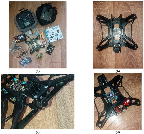
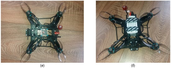
Figure 9.
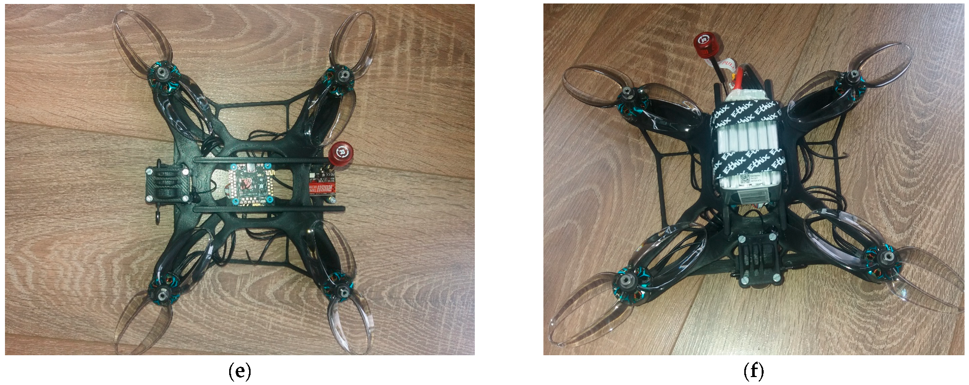
Stages of the quadcopter drone assembly process: (a) drone components; (b) mounting the FC and ESC in the central area of the frame; (c) mounting the FPV camera; (d) mounting the video transmitter and associated antenna; (e) mounting the motors and propellers; (f) mounting the battery.
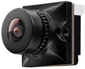
The FPV camera is mounted using two M2 screws to transmit images to the goggles (Figure 9c). Next, the video transmitter and antenna are secured with four M3 screws at the rear of the drone (Figure 9d). The radio receiver and its antenna are mounted in the central area at the front, under the GoPro camera mount. Next, mount the four motors, each with its own propeller (Figure 9e). Finally, the battery is attached with two Velcro strips to the frame rails (Figure 9f).
Next, the drone components are initialized to prepare it for flight. First, once the drone has been assembled and all the components connected, it must be connected to a computer via a USB cable. Most of the settings for the quadcopter drone areconfigured using the BetaFlight Configurator software, version 10.10.0.
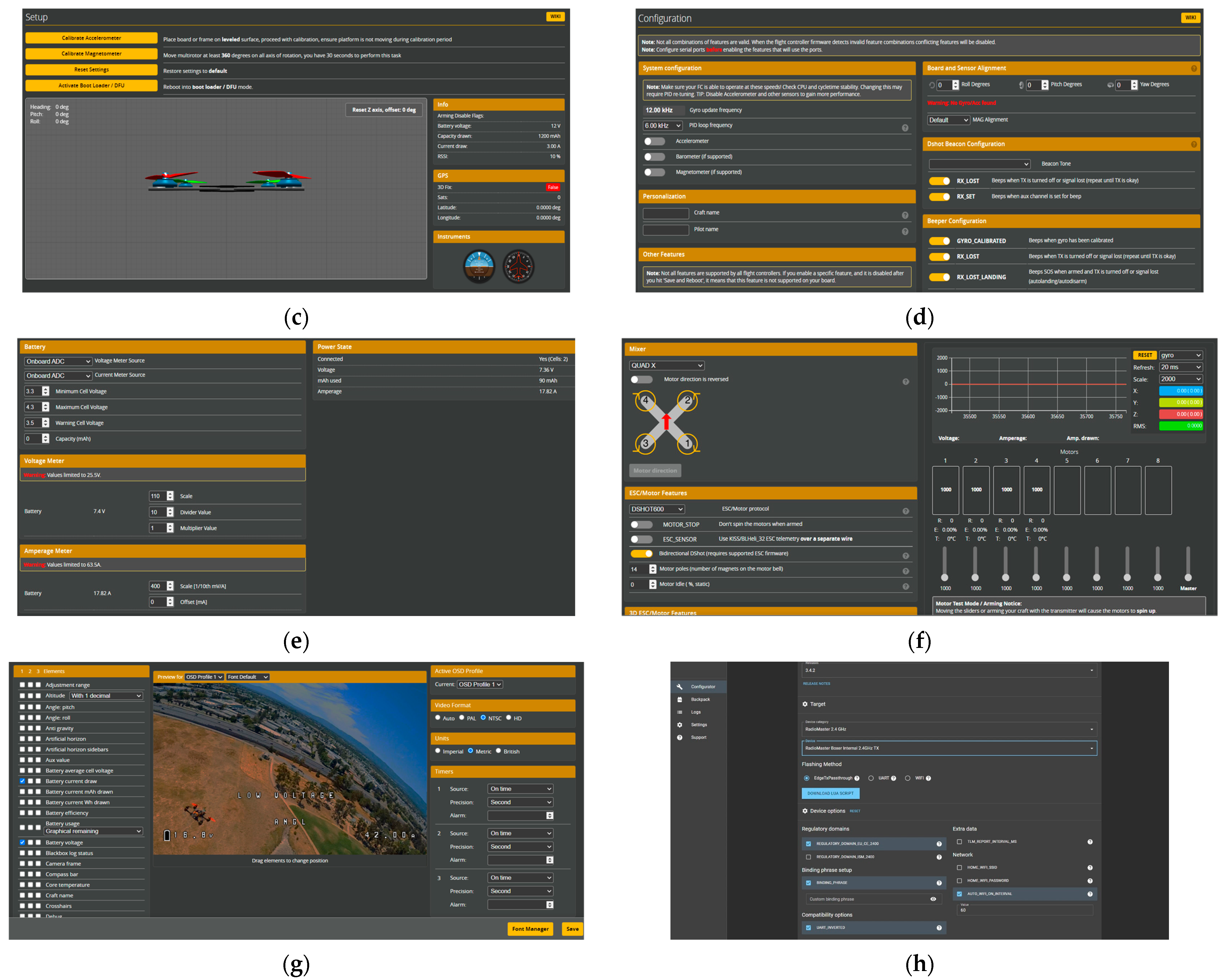
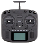
The verification process for the drone started with the installation of firmware on the radio receiver and flight controller (FC) via the ExpressLRS Configurator application (Figure 10a,b). Next, the accelerometer was calibrated (Figure 10c), the UART ports were set up for communication, and the gyroscope and accelerometer frequencies were adjusted, along with the signal loss alarm (Figure 10d). Battery operating limits were set to prevent wear and tear, and an OSD warning was added (Figure 10e). Radio control commands were then tested, followed by configuration of the motors’ rotation direction (Figure 10f). The OSD profiles were also customized to display essential information during flight (Figure 10g). Finally, the firmware was installed on the radio control (Figure 10h), after which functional and low-altitude flight tests were performed.

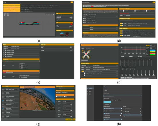
Figure 10.
Steps in the quadcopter drone operation checking process: (a) ExpressLRS Configurator–radio receiver firmware update; (b) FC firmware update; (c) accelerometer calibration; (d) gyroscope and accelerometer frequency setting; (e) setting battery alerts; (f) setting the motor rotation mode; (g) setting the OSD profiles; (h) radio control firmware update.
7. Conclusions
This study demonstrates progress in the additive technology and optimization of aerospace structures for UAVs. However, there is a gap in the integration of additive manufacturing technology and generative design methods in the manufacture of UAV structures. This study proposes to reduce this gap by combining these approaches to create higher-performance UAV structures. Given the importance of developing optimal structural designs for UAVs, this study is relevant and has the potential to contribute significantly to improving efficiency, performance, and innovation in the UAV industry and related industries in the future. The following conclusions can be drawn from this study:
- The advantages of generative design combined with additive processes are undeniable: reduced weight (18% reduction compared to the original carbon fibre version), design freedom, reduced material consumption, short manufacturing times and low costs, and a wide range of materials. This reduction in mass can be attributed to the low density of the Tough PLA material (1.22 g/cm3) and from the additively manufactured frame of the quadcopter drone. However, at present, the additive manufacturing technology required for a complex geometric structure such as a quadcopter drone frame is not yet sufficiently developed to be reliable for medium- or large-scale production, making it ideal for small-scale production and prototyping.
- Adaptability through the ability to create structures for different specifications (load values, structure shapes, or safety factors) that would otherwise be impossible to manufacture is an advantage over components made using conventional manufacturing methods. Another advantage is that the resulting quadcopter frame is a single component and does not require assembly like commercially available ones.
- The drone frame was quickly and easily prototyped using additive manufacturing processes involving extrusion of the material. Unlike traditional methods, such as CNC machining or injection moulding, FFF processes have several limitations in terms of production scalability. These include reduced cost and time efficiency at high volumes, low production speed, and inferior mechanical strength compared to composite materials. Conventional methods could not be used in this case due to the complexity of the model. However, although the material used is not as strong as a composite or metal material, it is strong enough to meet the criteria required for the design and operation of the quadcopter drone.
- Frame maintenance is difficult because Tough PLA filament requires a dry and cool environment to prevent rapid deterioration, which is facilitated by high humidity, high temperature, and prolonged exposure to UV rays. Usually, damage to the frame through cracking or breaking requires replacement with a new one, as repair is not possible or feasible.
- Finite element analysis (FEA) and functional testing have confirmed that the frame structure is sufficiently strong to withstand static and dynamic loads. Combined with significantly reduced production costs, these results validate the performance of the frame, which is representative of similar drones on the market.
In conclusion, this paper has demonstrated the feasibility of building a drone by completing all the stages required for the development of a UAV aeronautical product (preliminary design–generative design–finite element analysis–3D printing–assembly and operational testing). Future research will include scaling up the drone, changing the drone material (continuous fibre filament or high-strength polymers), adding a new mission with the ability to transport various products (medicines, emergency equipment, or even food), or using it for various inspections by adding sensors (gas detection and air monitoring), and increasing operational capability through the use of more powerful batteries and a ground control station.
Author Contributions
Conceptualization, V.A. and S.-M.Z.; methodology, V.A. and S.-M.Z.; software, V.A.; validation, S.-M.Z.; investigation, V.A. and S.-M.Z.; resources, S.-M.Z.; writing—original draft preparation, V.A. and S.-M.Z.; writing—review and editing, V.A. and S.-M.Z.; supervision, S.-M.Z.; funding acquisition, S.-M.Z. All authors have read and agreed to the published version of the manuscript.
Funding
This work was financially supported by the Transilvania University of Brasov.
Institutional Review Board Statement
Not applicable.
Informed Consent Statement
Not applicable.
Data Availability Statement
All data generated or analysed during this study are included in this published paper.
Conflicts of Interest
The authors declare no conflicts of interest.
References
- Sigmund, O.; Maute, K. Topology optimization approaches: A comparative review. Struct. Multidiscip. Optim. 2013, 48, 1031–1055. [Google Scholar] [CrossRef]
- Zhu, J.; Zhou, H.; Wang, C.; Zhou, L.; Yuan, S.; Zhang, W. A review of topology optimization for additive manufacturing: Status and challenges. Chin. J. Aeronaut. 2021, 34, 91–110. [Google Scholar] [CrossRef]
- Krish, S. A practical generative design method. Comput. Des. 2011, 43, 88–100. [Google Scholar] [CrossRef]
- Tang, T.; Wang, L.; Zhu, M.; Zhang, H.; Dong, J.; Yue, W.; Xia, H. Topology Optimization: A Review for Structural Designs Under Statics Problems. Materials 2024, 17, 5970. [Google Scholar] [CrossRef] [PubMed]
- Tyflopoulos, E.; Steinert, M. A Comparative Study of the Application of Different Commercial Software for Topology Optimization. Appl. Sci. 2022, 12, 611. [Google Scholar] [CrossRef]
- Ibhadode, O.; Zhang, Z.D.; Sixt, J.; Nsiempba, K.M.; Orakwe, J.; Martinez-Marchese, A.; Ero, O.; Shahabad, S.I.; Bonakdar, A.; Toyserkani, E. Topology optimization for metal additive manufacturing: Current trends, challenges, and future outlook. Virtual Phys. Prototyp. 2023, 18, 2181192. [Google Scholar] [CrossRef]
- Berrocal, L.; Fernández, R.; González, S.; Periñán, A.; Tudela, S.; Vilanova, J.; Rubio, L.; Martín Márquez, J.M.; Guerrero, J.; Lasagni, F. Topology optimization and additive manufacturing for aerospace components. Prog. Addit. Manuf. 2019, 4, 83–95. [Google Scholar] [CrossRef]
- Zhang, J.H.; Zhang, W.H.; Xia, L. Topology Optimization in Aircraft and Aerospace Structures Design. Arch. Comput. Methods Eng. 2016, 23, 595–622. [Google Scholar]
- Okorie, O.; Perveen, A.; Talamona, D.; Kostas, K. Topology Optimization of an Aerospace Bracket: Numerical and Experimental Investigation. Appl. Sci. 2023, 13, 13218. [Google Scholar] [CrossRef]
- Dalpadulo, E.; Pini, F.; Leali, F. Assessment of Computer-Aided Design Tools for Topology Optimization of Additively Manufactured Automotive Components. Appl. Sci. 2021, 11, 10980. [Google Scholar] [CrossRef]
- Zhang, Y.; Shan, Y.; Liu, X.; He, T. An integrated multi-objective topology optimization method for automobile wheels made of lightweight materials. Struct. Multidiscip. Optim. 2021, 64, 1585–1605. [Google Scholar] [CrossRef]
- Xie, Y.M. Generalized topology optimization for architectural design. Archit. Intell. 2022, 1, 2. [Google Scholar] [CrossRef]
- Gao, W.; Lv, X. Applications of Topology Optimization in Structural Engineering. Struct. Eng. 2020, 36, 232–241. [Google Scholar]
- Tan, N.; van Arkel, R.J. Topology Optimisation for Compliant Hip Implant Design and Reduced Strain Shielding. Materials 2021, 14, 7184. [Google Scholar] [CrossRef] [PubMed]
- Wu, N.; Li, S.; Zhang, B.; Wang, C.; Chen, B.; Han, Q.; Wang, J. The Advances of Topology Optimization Techniques in Orthopedic Implants: A Review. Med. Biol. Eng. Comput. 2021, 59, 1673–1689. [Google Scholar] [CrossRef]
- Oh, S.; Jung, Y.; Kim, S.; Lee, I.; Kang, N. Deep Generative Design: Integration of Topology Optimization and Generative Models. J. Mech. Des. 2019, 141, 111405. [Google Scholar] [CrossRef]
- Jang, S.; Yoo, S.; Kang, N. Generative Design by Reinforcement Learning: Enhancing the Diversity of Topology Optimization Designs. Comput.-Aided Des. 2022, 146, 103225. [Google Scholar] [CrossRef]
- Barbieri, L.; Muzzupappa, M. Performance-Driven Engineering Design Approaches Based on Generative Design and Topology Optimization Tools: A Comparative Study. Appl. Sci. 2022, 12, 2106. [Google Scholar] [CrossRef]
- Sun, H.; Ma, L. Generative Design by Using Exploration Approaches of Reinforcement Learning in Density-Based Structural Topology Optimization. Designs 2020, 4, 10. [Google Scholar] [CrossRef]
- Bhat, A.; Gupta, V.; Aulakh, S.S.; Elsen, R.S. Generative design and analysis of a double-wishbone suspension assembly: A methodology for developing constraint oriented solutions for optimum material distribution. J. Eng. Des. Technol. 2021, 21, 927. [Google Scholar] [CrossRef]
- McKnight, M. Generative Design: What it is? How is it being used? Why it’s a game changer. KnE Eng. 2017, 2, 176–181. [Google Scholar] [CrossRef]
- ISO/ASTM 52900:2021; Additive Manufacturing—General Principles—Fundamentals and Vocabulary. International Organization for Standardization: Geneva, Switzerland, 2021.
- Bermudo, C.; Trujillo, F.J.; Martín, S.; Herrera, M.; Sevilla, L. Fatigue behaviour analysis of AISI 316-L parts obtained by machining process and additive manufacturing. IOP Conf. Ser. Mater. Sci. Eng. 2021, 1193, 012101. [Google Scholar] [CrossRef]
- Sahini, D.; Ghose, J.; Jha, S.K.; Behera, A.; Mandal, A. Optimization and Simulation of Additive Manufacturing Processes: Challenges and Opportunities—A Review. In Additive Manufacturing Applications for Metals and Composites; IGI Global: Hershey, PA, USA, 2020; pp. 187–209. [Google Scholar]
- Ai, Y.; Ye, C.; Liu, J.; Zhou, M. Study on the evolution processes of keyhole and melt pool in different laser welding methods for dissimilar materials based on a novel numerical model. Int. Commun. Heat Mass Transf. 2025, 163, 108629. [Google Scholar] [CrossRef]
- Popișter, F.; Goia, H.Ș.; Ciudin, P.; Dragomir, D. Experimental Study of a 3D Printing Strategy for Polymer-Based Parts for Drone Equipment Using Bladeless Technology. Polymers 2024, 16, 533. [Google Scholar] [CrossRef] [PubMed]
- Baltić, M.Z.; Vasić, M.R.; Vorkapić, M.D.; Bajić, D.M.; Piteľ, J.; Svoboda, P.; Vencl, A. PETG as an Alternative Material for the Production of Drone Spare Parts. Polymers 2024, 16, 2976. [Google Scholar] [CrossRef] [PubMed]
- Ţura, D.M.; Zaharia, S.M. Design, additive manufacturing and testing of a quadcopter drone. Land Forces Acad. Rev. 2023, 28, 245–254. [Google Scholar] [CrossRef]
- Shelare, S.D.; Aglawe, K.R.; Khope, P. Computer Aided Modeling and Finite Element Analysis of 3-D Printed Drone. Mater. Today Proc. 2021, 47, 3375–3379. [Google Scholar] [CrossRef]
- MohamedZain, A.O.; Chua, H.; Yap, K.; Uthayasurian, P.; Jiehan, T. Novel Drone Design Using an Optimization Software with 3D Model, Simulation, and Fabrication in Drone Systems Research. Drones 2022, 6, 97. [Google Scholar] [CrossRef]
- Skarka, W.; Nalepa, R.; Musik, R. Integrated Aircraft Design System Based on Generative Modelling. Aerospace 2023, 10, 677. [Google Scholar] [CrossRef]
- Saadlaoui, Y.; Milan, J.-L.; Rossi, J.-M.; Chabrand, P. Topology optimization and additive manufacturing: Comparison of conception methods using industrial codes. J. Manuf. Syst. 2017, 43, 178–186. [Google Scholar] [CrossRef]
- Hurtado-Pérez, A.B.; Pablo-Sotelo, A.d.J.; Ramírez-López, F.; Hernández-Gómez, J.J.; Mata-Rivera, M.F. On Topology Optimisation Methods and Additive Manufacture for Satellite Structures: A Review. Aerospace 2023, 10, 1025. [Google Scholar] [CrossRef]
- Gao, B.; Yang, H.; Chen, W.; Wang, H. Topology Optimization of the Bracket Structure in the Acquisition, Pointing, and Tracking System Considering Displacement and Key Point Stress Constraints. Aerospace 2024, 11, 939. [Google Scholar] [CrossRef]
- Carter, W.; Erno, D.; Abbott, D.; Bruck, C.; Wilson, G.; Wolfe, J.; Finkhousen, D.; Tepper, A.; Stevens, R. The GE aircraft engine bracket challenge: An experiment in crowdsourcing for mechanical design concepts. In Proceedings of the 25th Annual International Solid Freeform Fabrication Symposium, Austin, TX, USA, 4–6 August 2014; pp. 4–6. [Google Scholar]
- Tyflopoulos, E.; Steinert, M. Combining Macro- and Mesoscale Optimization: A Case Study of the General Electric Jet Engine Bracket. Designs 2021, 5, 77. [Google Scholar] [CrossRef]
- Chen, Y.; Wang, Q.; Wang, C.; Gong, P.; Shi, Y.; Yu, Y.; Liu, Z. Topology Optimization Design and Experimental Research of a 3D-Printed Metal Aerospace Bracket Considering Fatigue Performance. Appl. Sci. 2021, 11, 6671. [Google Scholar] [CrossRef]
- Seabra, M.; Azevedo, J.; Araújo, A.; Reis, L.; Pinto, E.; Alves, N.; Santos, R.; Mortágua, J.P. Selective laser melting (SLM) and topology optimization for lighter aerospace componentes. Procedia Struct. Integr. 2016, 1, 289–296. [Google Scholar] [CrossRef]
- Shi, G.; Guan, C.; Quan, D.; Wu, D.; Tang, L.; Gao, T. An Aerospace Bracket Designed by Thermo-Elastic Topology Optimization and Manufactured by Additive Manufacturing. Chin. J. Aeronaut. 2020, 33, 1252–1259. [Google Scholar] [CrossRef]
- Marino, S.O.; Fayazbakhsh, K. Generative Design for 3D Printing of Advanced Aerial Drones. Bachelor’s Thesis, Toronto Metropolitan University, Toronto, ON, Canada, 2023. [Google Scholar]
- Sharma, U.; Singh, V.; Haorongbam, B.; Sharma, A.; Mallick, R. Optimizing Quadcopter Chassis through Generative Design: A Novel Approach. In Industry 4.0 and Advanced Manufacturing; Springer Nature: Singapore, 2024. [Google Scholar]
- Balayan, A.; Mallick, R.; Dwivedi, S.; Saxena, S.; Haorongbam, B.; Sharma, A. Optimal Design of Quadcopter Chassis Using Generative Design and Lightweight Materials to Advance Precision Agriculture. Machines 2024, 12, 187. [Google Scholar] [CrossRef]
- Darsin, M.; Pamungkas, W.J.; Syuhri, S.N.H.; Wibowo, R.K.K.; Basuki, H.A.; Djumharianto, D.; Yudistiro, D.; Choiron, M.A.; Wardana, M.K.A.; Thongchai, S. Advanced optimization of drone frame design through the application of generative design techniques and 3D printing technology. J. Mech. Sci. Technol. 2025, 39, 119–128. [Google Scholar] [CrossRef]
- Bright, J.; Suryaprakash, R.; Akash, S.; Giridharan, A. Optimization of Quadcopter Frame Using Generative Design and Comparison with DJI F450 Drone Frame. IOP Conf. Ser. Mater. Sci. Eng. 2021, 1012, 012019. [Google Scholar] [CrossRef]
- De Freitas Francisco, J.V.; Gonzales, M.A.C. Generative Design of a Cargo Drone. In Proceedings of the Mecsol 2022—Proceedings of the 8th International Symposium on Solid Mechanics, São Paulo, Brazil, 17–19 October 2022. [Google Scholar]
- Ong, W.; Srigrarom, S.; Hesse, H. Design methodology for heavy-lift unmanned aerial vehicles with coaxial rotors. In Proceedings of the AIAA SciTech Forum, San Diego, CA, USA, 7–11 January 2019. [Google Scholar]
- EASA—Operating a Drone. Available online: https://www.easa.europa.eu/en/domains/drones-air-mobility/operating-drone/open-category-low-risk-civil-drones (accessed on 29 March 2025).
- HQProp Flux 2207 Motor. Available online: https://www.hobbyrc.co.uk/hqprop-flux-2207-1980kv-motor (accessed on 29 March 2025).
- Propeller Foxeer Donut 5145. Available online: https://www.foxeer.com/foxeer-donut-5145-props-g-520 (accessed on 29 March 2025).
- Flight Controller Stack MAMBA MK4 F722 APP. Available online: https://www.diatone.us/apps/help-center (accessed on 29 March 2025).
- TATTU R-Line Version 3.0 6S Lipo Battery 1550mAh 22.2V 120C Lipo Battery with XT60 Plug for FPV Drone Helicopter RC Racing Quadcopter. Available online: https://www.amazon.com/Version-Battery-Helicopter-Quadcopter-Airplane/dp/B08RYZNYMJ?th=1 (accessed on 29 March 2025).
- FPV Video Transmitter Module Rush VTX Tank II. Available online: https://rushfpv.net/products/tank-ii-ultimate-vtx (accessed on 29 March 2025).
- FPV Camera. Available online: https://caddxfpv.com/products/ratel-2-1-1-8inch-starlight-sensor-freestyle-fpv-camera (accessed on 29 March 2025).
- FPV Antenna. Available online: https://rushfpv.net/products/rushfpv-cherry2-cherry-antenna-ii-5-8g?variant=44154033537194 (accessed on 29 March 2025).
- FPV Goggles. Available online: https://shop.iflight.com/iflight-fpv-goggles-with-dvr-function-pro1364?search=goggles (accessed on 29 March 2025).
- Radiomaster Boxer Radio Controller. Available online: https://www.radiomasterrc.com/products/boxer-radio-controller-m2?variant=45666886910183 (accessed on 29 March 2025).
- Foxeer ELRS 2.4G Receiver LNA. Available online: https://www.foxeer.com/foxeer-elrs-2-4g-receiver-lna-g-464 (accessed on 29 March 2025).
- Mark4 HD Carbon Fiber FPV Frame—Quadcopter Racing Drone Parts. Available online: https://www.amazon.com.au/MANGRY-Carbon-Freestyle-Wheelbase-Quadcopter/dp/B0CJ7CNF86?th=1 (accessed on 29 March 2025).
- Fusion Product Documentation. Available online: https://help.autodesk.com/view/fusion360/ENU/?guid=GD-OVERVIEW (accessed on 29 March 2025).
- Arunkumar, P.; Balaji, D.; Radhika, N.; Rajeshkumar, L.; Rangappa, S.M.; Siengchin, S. Effect of infill pattern on mechanical properties of 3D printed PLA-Zn composites for drone frame structures: A topology optimization integrated application study. Results Eng. 2025, 25, 104107. [Google Scholar] [CrossRef]
- Filippatos, A.; Markatos, D.; Theochari, A.; Pantelakis, S. Integrating Sustainability in Aircraft Component Design: Towards a Transition from Eco-Driven to Sustainability-Driven Design. Aerospace 2025, 12, 140. [Google Scholar] [CrossRef]
- Arslan, S.; Iskender, I.; Navruz, T.S. Finite Element Method-Based Optimisation of Magnetic Coupler Design for Safe Operation of Hybrid UAVs. Aerospace 2023, 10, 140. [Google Scholar] [CrossRef]
- Ultimaker PLA, Technical Data Sheet. Available online: https://um-support-files.ultimaker.com/materials/2.85mm/tds/PLA/Ultimaker-PLA-TDS-v5.00.pdf (accessed on 15 May 2025).
- Ultimaker Tough PLA, Technical Data Sheet. Available online: https://ultimaker.com/materials/s-series-tough-pla/ (accessed on 15 May 2025).
- Ultimaker ABS, Technical Data Sheet. Available online: https://um-support-files.ultimaker.com/materials/2.85mm/tds/ABS/Ultimaker-ABS-TDS-v5.00.pdf (accessed on 15 May 2025).
- Bandinelli, F.; Peroni, L.; Morena, A. Elasto-Plastic Mechanical Modeling of Fused Deposition 3D Printing Materials. Polymers 2023, 15, 234. [Google Scholar] [CrossRef] [PubMed]
- Zouaoui, M.; Gardan, J.; Lafon, P.; Makke, A.; Labergere, C.; Recho, N. A Finite Element Method to Predict the Mechanical Behavior of a Pre-Structured Material Manufactured by Fused Filament Fabrication in 3D Printing. Appl. Sci. 2021, 11, 5075. [Google Scholar] [CrossRef]
- Biswas, P.; Guessasma, S.; Li, J. Numerical prediction of orthotropic elastic properties of 3D-printed materials using mi-cro-CT and representative volume element. Acta Mech. 2020, 231, 503–516. [Google Scholar] [CrossRef]
- Torres, J.; Cotelo, J.; Karl, J.; Gordon, A.P. Mechanical property optimization of FDM PLA in shear with multiple objectives. J. Miner. Met. Mater. Soc. (Tms) 2015, 67, 1183–1193. [Google Scholar] [CrossRef]
- Witzgall, C.; Völkl, H.; Wartzack, S. Derivation and Validation of Linear Elastic Orthotropic Material Properties for Short Fibre Reinforced FLM Parts. J. Compos. Sci. 2022, 6, 101. [Google Scholar] [CrossRef]
- Stamate, M.-A.; Pupăză, C.; Nicolescu, F.-A.; Moldoveanu, C.-E. Improvement of Hexacopter UAVs Attitude Parameters Employing Control and Decision Support Systems. Sensors 2023, 23, 1446. [Google Scholar] [CrossRef]
- Liu, R.; Liu, Y.; Zhang, Y. State-Space Method-Based Frame Dynamics Analysis of the Six-Rotor Unmanned Aerial Vehicles. World Electr. Veh. J. 2025, 16, 331. [Google Scholar] [CrossRef]
Disclaimer/Publisher’s Note: The statements, opinions and data contained in all publications are solely those of the individual author(s) and contributor(s) and not of MDPI and/or the editor(s). MDPI and/or the editor(s) disclaim responsibility for any injury to people or property resulting from any ideas, methods, instructions or products referred to in the content. |
© 2025 by the authors. Licensee MDPI, Basel, Switzerland. This article is an open access article distributed under the terms and conditions of the Creative Commons Attribution (CC BY) license (https://creativecommons.org/licenses/by/4.0/).


