Article

Determination of the Radius of the Ring Current in the Earth’s Core According to the Data of the INTERMAGNET Network Observatories

1
Special Design and Technology Bureau “Granit”, 292 Hussainov Street, 050060 Almaty, Kazakhstan
2
Institute of Ionosphere, 117 “Ionosphere” Gardening Association, Kamenskoye Plateau, 050020 Almaty, Kazakhstan
*
Author to whom correspondence should be addressed.
Appl. Sci. 2025, 15(17), 9633; https://doi.org/10.3390/app15179633 (registering DOI)
Submission received: 2 August 2025 / Revised: 29 August 2025 / Accepted: 30 August 2025 / Published: 1 September 2025

Abstract

The geomagnetic dynamo is currently considered the most likely source of the Earth’s main dipole field. However, the radius of the current ring located in the Earth’s core is not reliably known. There are methods for indirectly estimating the radius of this current. Another method is proposed that allows one to indirectly estimate the radius of the current ring inside the Earth’s core based on measurements of the Earth’s magnetic field by observatories included in the INTERMAGNET network. The results of measurements taken on a day with low magnetic activity were compared using the least squares method with fields that could be created by ring currents of different diameters at the locations of magnetic observatories. The assumption was made that the ring current in the model used is located in the plane of the Earth’s equator with the center coinciding with the axis of rotation of the Earth. Estimates of the current radius in the range of 957–1595 km were obtained, which corresponds to the boundary between the solid and liquid cores of the Earth. These results can refine the model of the structure of the Earth’s core and Earth’s magnetism.

1. Introduction

Having created the “Magnetische Verein” in 1834 [1], Gauss and Weber initiated systematic observations of the Earth’s magnetic field. Despite the vast amount of accumulated data from many years of observations, the nature of the origin of the Earth’s magnetic field is still a mystery. At the moment, there is a clear agreement only that there are several independent sources of the magnetic field. After the discovery of the Earth’s liquid core and the creation of the theory of geodynamo, the division of the sources of the Earth’s magnetic field into four main ones became the most widespread:
-
The liquid core of the Earth, generating the main dipole field;
-
The lithospheric field created by magnetized rocks;
-
The external field created by currents flowing in the ionosphere;
-
Electromagnetic induction field created by currents of the crust and outer mantle [2].
Currently, there is no consensus on the mechanisms and structure of the geomagnetic dynamo. There are several theoretical models [3] capable of describing the processes of magnetic field generation, each of which is based on its kinematic models of fluid motion in the Earth’s core. There are papers suggesting other hypotheses of the occurrence of a magnetic field in the Earth’s core, such as the hypothesis of the presence of geothermic currents [4]. There are also other theories of the origin of the magnetic field of planets and stars [5].
The advent of low-orbit magnetic observatories has allowed us to obtain a lot of new and valuable data on the structure of the Earth’s magnetic field and create fairly accurate models of it, but for these satellites, ionospheric currents flowing at altitudes of 110 km turned out to be “internal” currents, which makes it difficult to separate the sources of the magnetic field by their relative contribution to the total field [6]. The ability, according to ground-based magnetic observatories measurements, to separate the fields created in the Earth’s ionosphere and inside the Earth turned out to be very important. Nevertheless, space missions have clearly shown the importance of gradient measurements of the magnetic field. The Swarm mission, started in 2013, launched three satellites [7], two of which fly on the orbit with an initial altitude of about 450 km, measuring the field gradient in the east–west direction, and the third satellite is 100 km higher above them, measuring the vertical field gradient. The data obtained during the Swarm mission made it possible to “create” 300 virtual observatories evenly distributed above the Earth’s surface [8].
Of course, it is impossible to solve the inverse problem of magnetometry in a general way. However, if magnetic observatories are located in a certain way in space relative to the current source and there are a limited number of variants of the topology of this current, then using the least squares method, it is possible to determine a variant of the topology of the field source that could create the magnetic field closest to the observed one [9]. In the seventies of the last century, 36 magnetic observatories were installed in Scandinavia to study auroral currents with distances between stations of 100–150 km and with their orientation in the north–south and east–west directions [10] with a Cartesian coordinate system common to all stations. Another example would be their 10 AUTUMNX magnetometer array in North America [11].
In [12], an attempt was made to solve the inverse problem of magnetometry using the IGRF-2005 magnetic field model. In this work, the sources of the magnetic field were represented as virtual magnetized prisms located in the Earth’s core. Only the Z component of the magnetic field was analyzed. Four significant inhomogeneities were identified that create the Canadian, Siberian-Asian, Australian, and negative South Atlantic global magnetic anomalies observed on the Earth’s surface.
In [13], based on the average monthly three-component data from magnetic observatories, the contributions to the Earth’s total magnetic field from sources located in the core, lithosphere, ionosphere, and magnetosphere were separated. The authors obtained the radius of the sphere in the Earth’s core equal to 2658.2 km. This radius roughly corresponds to the region of the liquid core located in the middle between the boundary of the solid core of the Earth and the outer boundary of the liquid core with the lower mantle.
In [9], which considers the dipole model of the magnetic field, data are provided that dipole sources of the magnetic field are detected at a distance of approximately 0.2 Earth radii, which is 1276 km.
The purpose of this work is to determine the radius of the source of the dipole magnetic field located inside the Earth, according to the data of the ground-based magnetic observatories of the INTERMAGNET network. We have proposed a method for determining the radius of a current ring using vector algebra and the least squares method. Although there may be many such rings and they may be of different diameters, the dipole magnetic field will be a superposition of the fields of ring currents.

2. Materials and Methods

The induction of the magnetic field of a current element at any point in space is described by the Biot–Savart Equation (1), explained in Figure 1.
d B = μ 4 π I d l × a a 3 ,   a 0
Figure 1 shows the Cartesian XYZ coordinate system with the center located in the center of the Earth. The direction of the X axis corresponds to the direction of the prime meridian. In the plane of the equator (XOY), a ring current with a radius of R flows, creating a magnetic moment Pm directed along the axis of rotation of the Earth in the direction of the north pole. The magnetic observatory M is located at a point with polar coordinates (r, λ, φ), where r is the radius of the Earth, λ is the geographical longitude of the observatory, and φ is its geographical latitude.
The distance from the ring current element dl, which creates the field dB at the observation point, is indicated in Figure 1 as a. By integrating Equation (1) along the circle R, the total value of the field strength B at the observation point is obtained. For the case of a ring current, for example, formulas for calculating field components in polar coordinates are given in [14]. In this paper, formulas from [15] were used to calculate the components of the field strength at the observation point in Cartesian coordinates, which is more convenient for further calculations. The formulas used are given in Equation (2). A number of variables in the formulas have been replaced by the symbols from Figure 1 for ease of understanding.
B x = μ 0 I R r sin φ 4 π cos λ 0 2 π cos θ R 2 + r 2 2 R r cos φ · cos θ 3 2 d θ B y = μ 0 I R r sin φ 4 π sin λ 0 2 π cos θ R 2 + r 2 2 R r cos φ · cos θ 3 2 d θ   B z = μ 0 I R 4 π 0 2 π R r cos φ · cos θ R 2 + r 2 2 R r cos φ · cos θ 3 2 d θ
It follows from these equations that if the field is measured outside the radius of the current ring, but in the plane of the ring itself (z = 0), then the magnetic field vector will always be parallel to the axis of the current ring (Bx = By = 0). If the field is measured outside the plane of the ring, the magnetic field vector will deviate radially. The dominant contribution to the level of the field itself, and to the slope of the vector, will be made by the current flowing in the part of the ring that is closer to the measuring point d B 1 a 2 . Thus, knowing the coordinates of the measuring point and the values of the magnetic field vector, it is possible to create an equation of a plane in space that will necessarily intersect near the ring with the current. Formula (2) is convenient because it relates the polar coordinates of the field measurement points, which usually specify the geographical coordinates of objects on the Earth’s surface, to the Cartesian coordinates of the magnetic field components, which make it mathematically simple to obtain the equation of the plane for a known point in space and the field vector. The equation of the plane for a point O 1 x 1 ; y 1 ; z 1 and a vector B B x ; B y ; B z will have the form (3).
B x x x 1 + B y y y 1 + B z z z 1 = 0
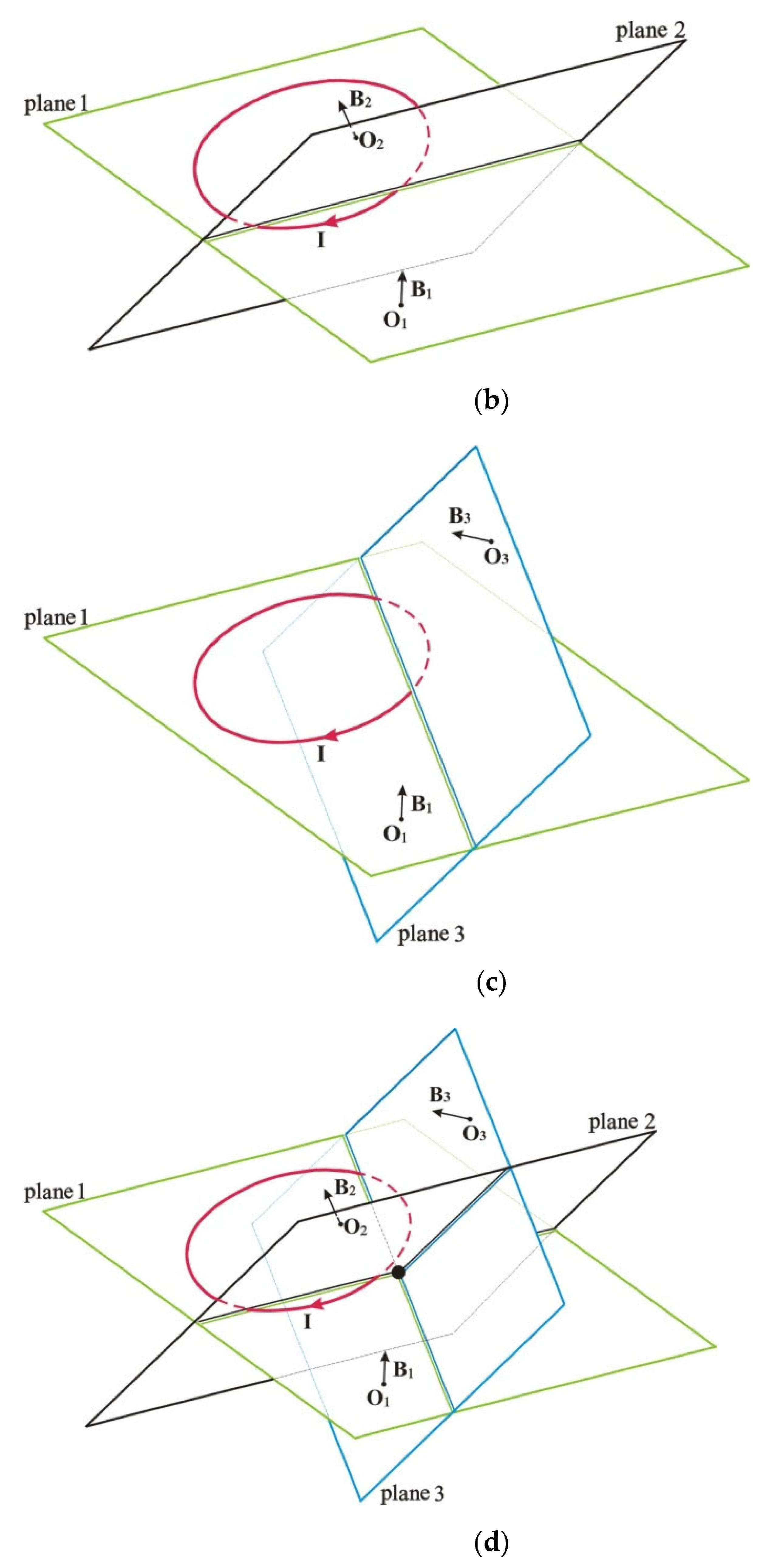
This is a linear equation with 3 unknowns. By making measurements at another observation point located outside the ring plane, you can create an equation for another plane. The line of intersection of these planes will pass near the current ring. By choosing the third observation point, a third plane will be obtained, and the combined solution of three linear equations with three unknowns will give a coordinate in space located at some distance from the current ring. A graphical explanation of the method is illustrated in Figure 2.
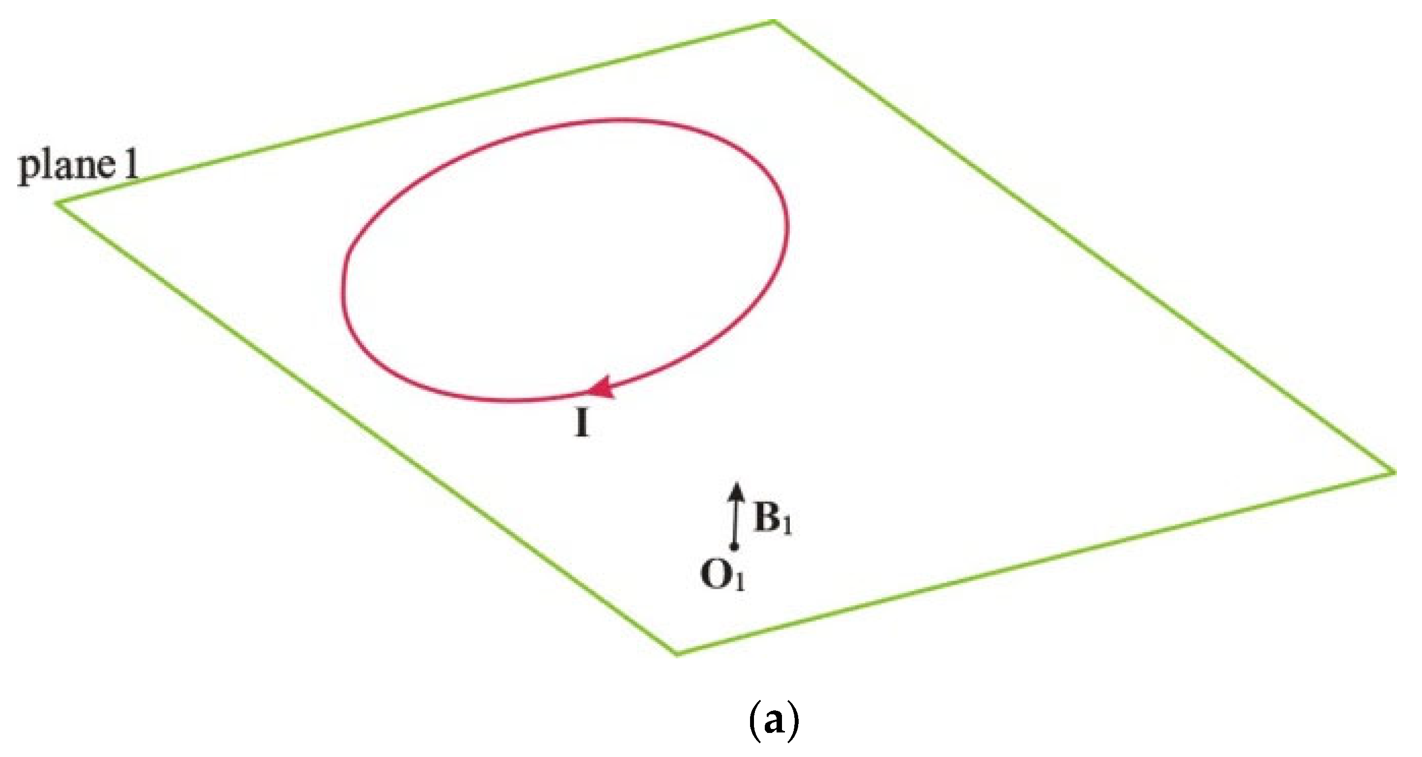
Figure 2a shows a ring with a current I, the vector of magnetic induction B1, measured at the observatory O1, located on the “plane 1” in which this ring is located. Figure 2b shows the intersection of “plane 1” and “plane 2”, which was constructed from the measurement of magnetic field induction B2, measured at the O2 observatory, located on the “plane 2”. Figure 2c shows the intersection of “plane 1” and “plane 3”, which was constructed from the measurement of magnetic field induction B3, measured at the O3 observatory located on the “plane 3”. Figure 2d shows the intersection of three planes and their intersection point. To solve systems of three linear equations with three unknowns, the Kramer (Gabriel Cramer) method was used.
The distance of this intersection point of planes from the edge of the ring will depend on the coordinates of the magnetic field measurement points relative to the ring with current and the radius of the ring itself. To evaluate the effectiveness of the proposed method, we will simulate the measurements that will be carried out by virtual magnetic observatories located on the surface of the sphere with a radius R. As a source of magnetic induction, we will consider a ring with a current I, which has a radius of 0.25R and is in the plane of zero latitude (in polar coordinates). By changing the coordinates of the observation points (longitude and latitude), we will estimate the distance of the resulting intersection point of three planes from the edge of the ring with current. This will allow us to optimally form triplets of real magnetic observatories to calculate the size of the ring current inside the Earth.
We denote the spherical coordinates of the base “virtual” observatory φ0, λ0, located on the surface of a sphere with a radius R equal to the average radius of the Earth 6380 km. The coordinates of the two additional observatories are shifted in latitude and longitude by an angle of Δ. The coordinates of the second observatory will be (φ0 + Δ, λ0), and the coordinates of the third observatory (φ0, λ0 + Δ).
Given different coordinates of the base observatory in latitude and different distances between the observatory, we calculate the coordinates of the intersection point of the three planes passing through the points with the coordinates of the “virtual” observatories and perpendicular to the magnetic field vectors calculated for these coordinates. The calculation results are shown in Table 1, Table 2 and Table 3. For ease of analysis, the coordinates of the points calculated in the Cartesian coordinate system with the Z axis pointing from the center of the sphere towards the north pole were recalculated into values r = x 2 + y 2 corresponding to the distance of the obtained point from the OZ axis, and Δz = z corresponding to the deviation of the obtained point from the equatorial plane. All distances are given in kilometers.
When performing modeling for the base station latitude φ0 = 0°, the value φ0 = 0.00001° was used. This was chosen because any stations located in the plane of the current ring have magnetic field vectors strictly parallel to each other, which means that for them, the equations of planes will be identical and there will be no intersection of planes. A small shift in the latitude of station coordinates eliminates this problem.
The third case, with the ring current radius of 0.9R-Earth, does not correspond to the geomagnetic dynamo theory. Nevertheless, it was modeled to reveal the possibilities of the method under consideration. The analysis of the results obtained in the modeling showed that the smaller the distances between the observatories and the closer they are to the equatorial plane, the closer the coordinates of the intersection points of the planes are to the edge of the ring with current. As the radius of the current ring increases, the intersection points of the planes also move away from the axis of the current ring.
Thus, if we form groups of three magnetic observatories each, from among the observatories included in the INTERMAGNET network, and select a day with low geomagnetic activity, we can obtain a set of intersection points of planes normal to the vectors of the field recorded by the magnetic observatories. Then, setting different radii of the virtual ring with current, we can calculate similar points of intersection of planes for the modeled ring currents. Using the method of least squares, it is possible to find such a radius of the ring current, at which the minimum discrepancy between the coordinates of the points obtained during modeling and those obtained from the results of the real measurement of the magnetic field strength will be obtained.
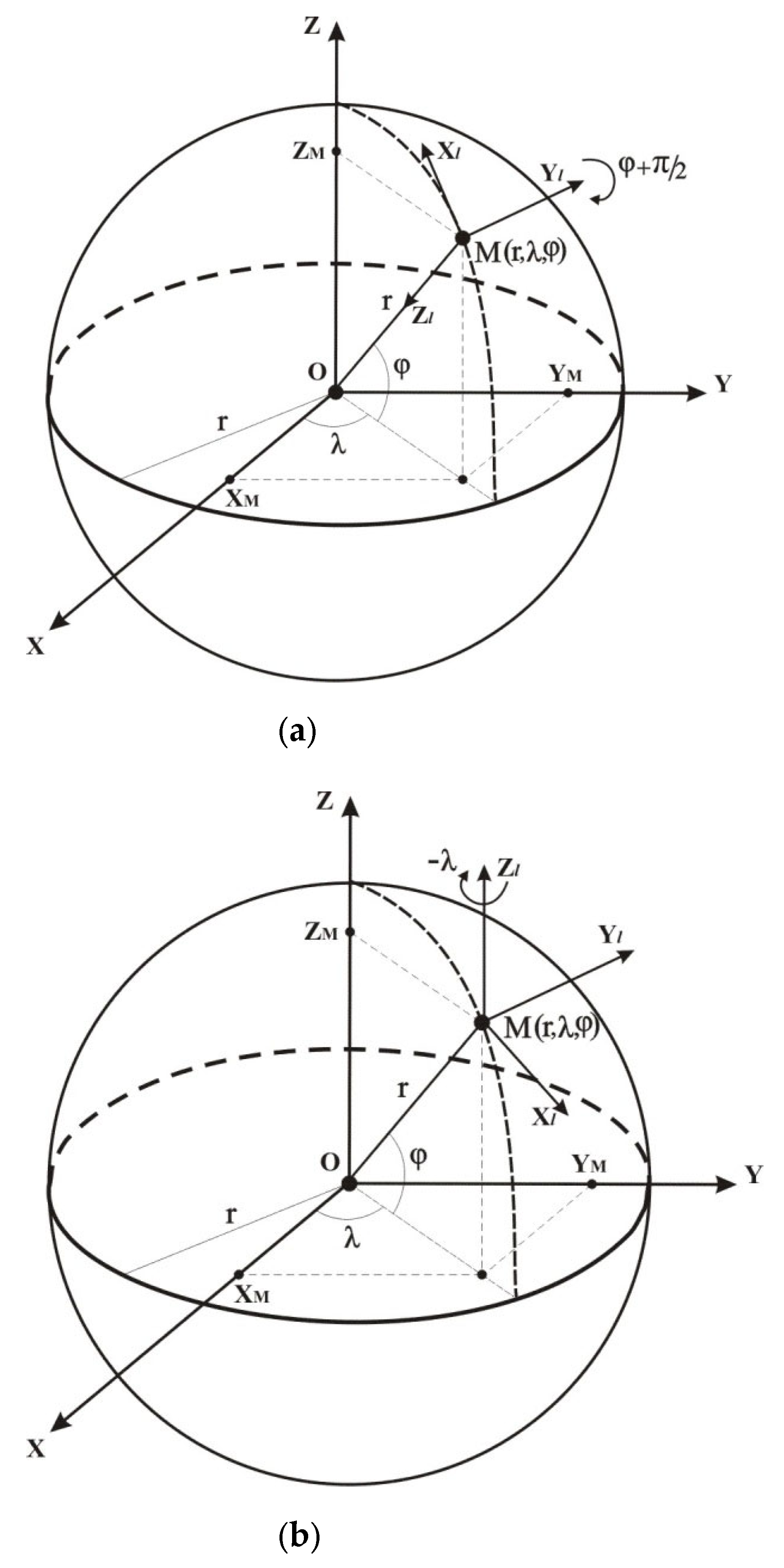
Before using data from real magnetic observatories for calculations, they must be previously modified. All magnetic observatories measure projections of the Earth’s magnetic field in local Cartesian coordinate systems that are unique to each observatory. The X and Y axes of these coordinate systems are located in the plane tangent to the surface of the geoid at the location of the magnetic observatory and are oriented in the directions to the geographical “north” and “east”, respectively, and the Z axis is directed to the center of the Earth (Figure 3).
To bring the local coordinate systems to the universal Cartesian coordinates, it is necessary to perform two rotations of the coordinate systems. First, rotate around the Y axis of the local coordinate system using the rotation matrix (4) by an angle of φ + π/2 in order to orient the local Z axis in a direction parallel to the Z axis of the general terrestrial coordinate system (Figure 3a).
R y φ + π 2 = cos φ + π 2 0 sin φ + π 2 0 1 0 sin φ + π 2 0 cos φ + π 2
The second rotation must be made around the Z axis (Figure 3b) by an angle of −λ in accordance with the rotation matrix (5), so that the X and Y axes of the local systems become parallel to the corresponding axes of the global coordinate system.
R z λ = cos λ sin λ 0 sin λ cos λ 0 0 0 1

3. Results

To perform the modeling, the measurement results of the magnetic observatories included in the INTERMAGNET network were taken for one of the days in which there were no disturbances in the Earth’s magnetic field. The date chosen was 23 October 2005. The ap index, which characterizes the planetary amplitude of magnetic field variations for mid-latitude magnetic observatories, was chosen as the selection criterion for a day with low geomagnetic activity. The ap index values are shown in Table 4.
The year 2005 was not chosen for any special reasons, it was chosen because the data of this year were processed in order to study the dynamics of magnetic disturbances and synchronization problems of geomagnetic observatories [16]. The averaged daily components of the magnetic field were used for the simulation.
On the selected date, data from 98 observatories out of 154 included in the INTERMAGNET network were available. A review of the magnetograms revealed data omissions at 28 observatories, which were removed from the total number of observatories. In total, data from 70 observatories shown in Table 5 were used in the modeling.
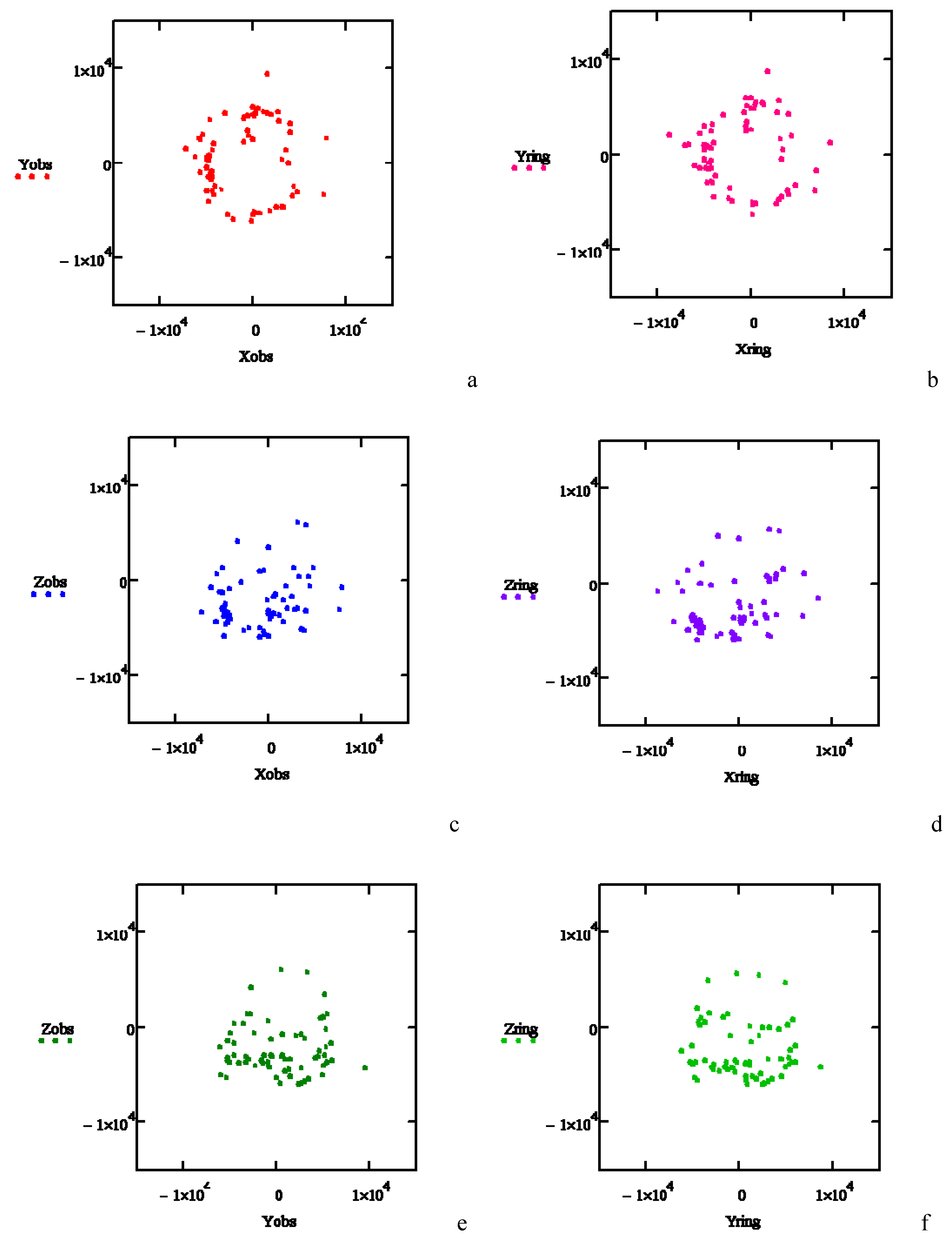
Two more observatories were matched to each observatory to find the intersection points of the planes. The obtained intersection points are shown in Figure 4a,c,e. The coordinates of the intersection points in the figure are given in kilometers.
For comparison, Figure 4b,d,e show the results of modeling the plane intersection points for the magnetic field calculated for a current ring with a radius of 0.5 Earth radius located in the equatorial plane centered at the Earth’s center. The magnetic field magnitude was calculated using Equation (2) for a sphere with a radius of 6380 km.
As can be seen from Figure 4, the constellations of points obtained from real magnetic field measurements and those obtained from the ring current field modeling look similar in appearance. Since in the case of modeling the field from the ring current, we know the geometry of the current ring exactly, and the appearance of the “constellations” of intersection points in Figure 4a,c,e is very close in topology to similar “constellations” in Figure 4b,d,f, we can expect that the magnetic field source also has a ring structure.
To solve the problem of determining the radius of the ring current that formed the magnetic field closest to that measured by real magnetic observatories, we calculate the functional (6) for each triple of observatories:
r i = X o b s i X r i n g i 2 + Y o b s i Y r i n g i 2 + Z o b s i Z r i n g i 2
where Xobsi, Yobsi, Zobsi are the coordinates of points obtained from real measurements of magnetic observatories, and Xringi, Yringi, Zringi are the coordinates of points obtained from modeling the magnetic field of the ring current for the i-th triple observatories.
We calculate the average ( Δ r ¯ ) and root-mean-square ( σ Δ r ) values of this functional for all 70 groups of observatories at different values of the radius of the ring current. The results obtained in kilometers are shown in Table 6.

4. Discussion

The obtained coincidence of the topologies of the “constellations” of the intersection points of the planes calculated for the real Earth’s magnetic field and for the simulated ring current was expected. The radii of the ring current inside the Earth turned out to be unexpected. We expected to obtain a result close to that obtained in [12] based on the average monthly three-component data from magnetic observatories. The radius of the sphere of 2658.2 km obtained by these authors could not be so accurate in practice. The processes in the Earth’s core are more global and precision in tenths of a kilometer is out of the question.
Aksenov’s work [17] states that the radius of a toroidal ring current is equal to 1437 km. This value differs significantly from the data from the previous work. During the simulation, the difference between the outer and inner diameters of the torus was set to 3 km.
Using the least squares method, we planned to estimate the real boundaries of the inner and outer radii of the current ring, since the ring thickness of 3 km clearly does not correspond to the scale of the processes taking place inside the Earth. The results obtained allowed us to estimate the width of the ring current in the range from 0.15 to 0.25 of Earth radius, which is 957–1595 km. But these values are located in the boundary layer of solid and liquid nuclei. Researchers of the solid core structure previously drew attention to the presence of the innermost core with a radius of 300–600 km [18,19].
Probably, the division of the core into a solid core and a liquid core is not very strict. Perhaps, there is some “semi-liquid” part of the core. Doubts about the existence of a strict boundary between the solid and liquid core of the Earth have existed for a long time [20]. It was shown in [21] that geophysicists underestimated the viscosity of the boundary layer between the solid core and the liquid core. Recent advances in the emerging paradigm of the correlation-wave field [22] give hope that it will be possible to interpret the obtained seismograms more accurately and clarify the physics of the processes occurring at the boundary of the solid and liquid cores of the Earth.
Another possible interpretation of the obtained results could be the presence of current rings of various diameters located on the surface of a certain sphere. In this case, the maximum radius of the ring obtained will correspond to the radius of such a sphere in the plane of the equator.
For verification, we performed calculations for several more days, including days with low magnetic activity. However, qualitatively, the results did not change. The Earth’s main magnetic field, measured on its surface, is in the range of 30,000 to 60,000 nanotesla, depending on the geographical location of the measurements, which is significantly higher than the variations associated with magnetic storms (several hundred nanotesla), as well as daily Sq variations. Averaging measurements per day reduces the effect of variations. The presence of errors related to magnetic storms or diurnal variations can lead to a change of the inclination of the planes by no more than 0.01 radians, which can lead to errors in determining the coordinates of the intersection point within 0.01 Earth radius.
We also did not take into account the actual height of the magnetic observatories above sea level. Such a simplification could not cause any significant errors, as it leads to a displacement of the planes passing through the geographical locations of the observatories and, accordingly, the points of intersection of these planes by an amount not exceeding units of kilometers.
A copyright certificate was obtained for the developed software [23]. The text of the program can be obtained from the authors of the article.

5. Conclusions

The obtained estimates of the radius of the ring current inside the Earth, which is considered the most likely source of the dipole component of the Earth’s magnetic field, may provide new initial data for clarifying models of Earth’s magnetism.
Modern capabilities of computers make it possible to test various hypotheses about the geometric topology and intensity of currents inside the Earth, in order to identify configurations in which the calculated field most closely coincides with the observed field. The ring model used in the work was only a simplification to facilitate the demonstration of the proposed method.
Studying the dynamics of changes of the coordinates of the points of intersection of planes can help identify magnetic observatories, the quality of which should either be questioned, or it could provide additional information about the geophysical processes occurring in the depths of the Earth.

Author Contributions

Conceptualization, I.V.; Data curation, B.Z.; Formal analysis, Z.M., B.Z. and I.K.; Funding acquisition, Z.M.; Investigation, I.V.; Methodology, I.V.; Project administration, Z.M.; Resources, B.Z.; Software, I.F.; Supervision, Z.M.; Validation, Z.M., B.Z. and I.K.; Visualization, I.F.; Writing—original draft, I.V.; Writing—review and editing, Z.M. All authors have read and agreed to the published version of the manuscript.

Funding

This research was funded by the Science Committee of the Ministry of Science and Higher Education of the Republic of Kazakhstan (Grant No. AP19679336-“Development of methods for increasing the efficiency of using geomagnetic variations as earthquake precursors”).

Data Availability Statement

The necessary data are available from the corresponding author upon reasonable request.

Acknowledgments

The results presented in this paper rely on geomagnetic indices calculated and made available by ISGI Collaborating Institutes from data collected at magnetic observatories. We thank the involved national institutes, the INTERMAGNET network and ISGI (isgi.unistra.fr), accessed on 1 September 2025.

Conflicts of Interest

Author Ivan Vassilyev was employed by the company Special Design and Technology Bureau “Granit”. The remaining authors declare that the research was conducted in the absence of any commercial or financial relationships that could be construed as a potential conflict of interest.

References

  1. Cawood, J. Terrestrial magnetism and the development of international collaboration in the early nineteenth century. Ann. Sci. 1977, 34, 551–587. [Google Scholar] [CrossRef]
  2. Lanza, R.; Meloni, A. The Earth’s Magnetic Field. In The Earth’s Magnetism; Springer: Berlin/Heidelberg, Germany, 2006; pp. 1–66. [Google Scholar] [CrossRef]
  3. Roberts, P.H.; King, E.M. On the genesis of the Earth’s magnetism. Rep. Prog. Phys. 2013, 76, 096801. [Google Scholar] [CrossRef] [PubMed]
  4. Dmitriev, A.N. A New Look On the Nature of the Earth’s Magnetic Field. IOP Conf. Ser. Earth Environ. Sci. 2016, 44, 022001. [Google Scholar] [CrossRef]
  5. Qin, S. Theoretical Explanation and Experimental Design of the Origin of Earth’s Magnetic Field, Stellar Magnetic Field, and Neutron Star Magnetic Field. Preprints 2023, 2023040009. [Google Scholar] [CrossRef]
  6. Olsen, N.; Moretto, T.; Friis-Christensen, E. New approaches to explore the Earth’s magnetic field. J. Geodyn. 2002, 33, 29–41. [Google Scholar] [CrossRef]
  7. Friis-Christensen, E.; Lühr, H.; Hulot, G. Swarm: A constellation to study the Earth’s magnetic field. Earth Planets Space 2006, 58, 351–358. [Google Scholar] [CrossRef]
  8. Hammer, M.D.; Cox, G.A.; Brown, W.J.; Beggan, C.D.; Finlay, C.C. Geomagnetic Virtual Observatories: Monitoring geomagnetic secular variation with the Swarm satellites. Earth Planets Space 2021, 73, 54. [Google Scholar] [CrossRef]
  9. Alldredge, L.R.; Stearns, C.O. Dipole model of the sources of the Earth’s magnetic field and secular change. J. Geophys. Res. 1969, 74, 6583–6593. [Google Scholar] [CrossRef]
  10. Kuppers, F.; Untiedt, J.; Baumjohann, W.; Lange, K.; Jones, A. A two-dimensional magnetometer array for ground-based observations of auroral zone electric currents during the International Magnetospheric Study (IMS). J. Geophys. 1979, 46, 429–450. Available online: https://journal.geophysicsjournal.com/JofG/article/view/160 (accessed on 29 August 2025).
  11. Connors, M.; Schofield, I.; Reiter, K.; Chi, P.J.; Rowe, K.M.; Russell, C.T. The AUTUMNX magnetometer meridian chain in Québec, Canada. Earth Planet Space 2016, 68, 2. [Google Scholar] [CrossRef]
  12. Kochnev, V. Distribution of Sources of Magnetic Field in the Earth’s Core Obtained by Solving Inverse Magnetometry Problem. In Practical and Theoretical Aspects of Geological Interpretation of Gravitational, Magnetic and Electric Fields; Nurgaliev, D., Khairullina, N., Eds.; Springer Proceedings in Earth and Environmental Sciences: Springer, Cham, 2019. [Google Scholar] [CrossRef]
  13. Holschneider, M.; Lesur, V.; Mauerberger, S.; Baerenzung, J. Correlation-based modeling and separation of geomagnetic field components. J. Geophys. Res. Solid Earth 2016, 121, 3142–3160. [Google Scholar] [CrossRef]
  14. Li, B.; Yang, B.; Xiang, F.; Guo, J.; Li, H. The Source Structure Design of the Rotating Magnetic Beacon Based on Phase-Shift Direction Finding System. Sensors 2022, 22, 8304. [Google Scholar] [CrossRef] [PubMed]
  15. Perov, N.S.; Granovskij, S.A.; Strelkov, N.V.; Shapaeva, T.B.; Makarova, L.A.; Shapaev, B.A. Izuchenie Postojannogo Magnitnogo Polja. Chislennoe Modelirovanie i Jeksperiment [Study of a Constant Magnetic Field. Numerical Simulation and Experiment]. Moscow 2017, 23p. Available online: http://magn.phys.msu.ru/Rus/praki/magneticfield.pdf (accessed on 29 August 2025). (In Russian).
  16. Vassilyev, I.V.; Mendakulov, Z.K.; Fedulina, I.N.; Zhumabayev, B.T. Method for revealing the violation of synchronization in the operation of geomagnetic observatories of INTERMAGNET network. Acta Geophys. 2025, 73, 3045–3055. [Google Scholar] [CrossRef]
  17. Aksenov, V.V. Modelirovanie toroidal’nyh i poloidal’nyh elektromagnitnyh polej [Modeling of toroidal and poloidal electromagnetic fields]. Mat. Model. 2014, 26, 3–24. (In Russian). [Google Scholar]
  18. Deguen, R. Structure and dynamics of Earth’s inner core. Earth Planet. Sci. Lett. 2012, 333–334, 211–225. [Google Scholar] [CrossRef]
  19. Ishii, M.; Dziewoński, A.M. The innermost inner core of the earth: Evidence for a change in anisotropic behavior at the radius of about 300 km. Proc. Natl. Acad. Sci. USA 2002, 99, 14026–14030. [Google Scholar] [CrossRef] [PubMed]
  20. Jacobs, J. The Earth’s Inner Core. Nature 1953, 172, 297–298. [Google Scholar] [CrossRef]
  21. Smylie, D.E.; McMillan, D.G. Viscous and rotational splitting of the translational oscillations of Earth’s solid inner core. Phys. Earth Planet. Inter. 1998, 106, 1–18. [Google Scholar] [CrossRef]
  22. Tkalčić, H.; Wang, S.; Phạm, T. Shear Properties of Earth’s Inner Core. Annu. Rev. Earth Planet. Sci. 2022, 50, 153–181. [Google Scholar] [CrossRef]
  23. Vassilyev, I.V.; Fedulina, I.N. Certificate of Entry of Information into the State Register of Rights to Objects Protected by Copyright № 57172 of the Republic of Kazakhstan. Determination of coordinates of magnetic field sources according to INTERMAGNET Observatories. 24 April 2025. Available online: https://copyright.kazpatent.kz/?!.iD=wQEy (accessed on 29 August 2025).
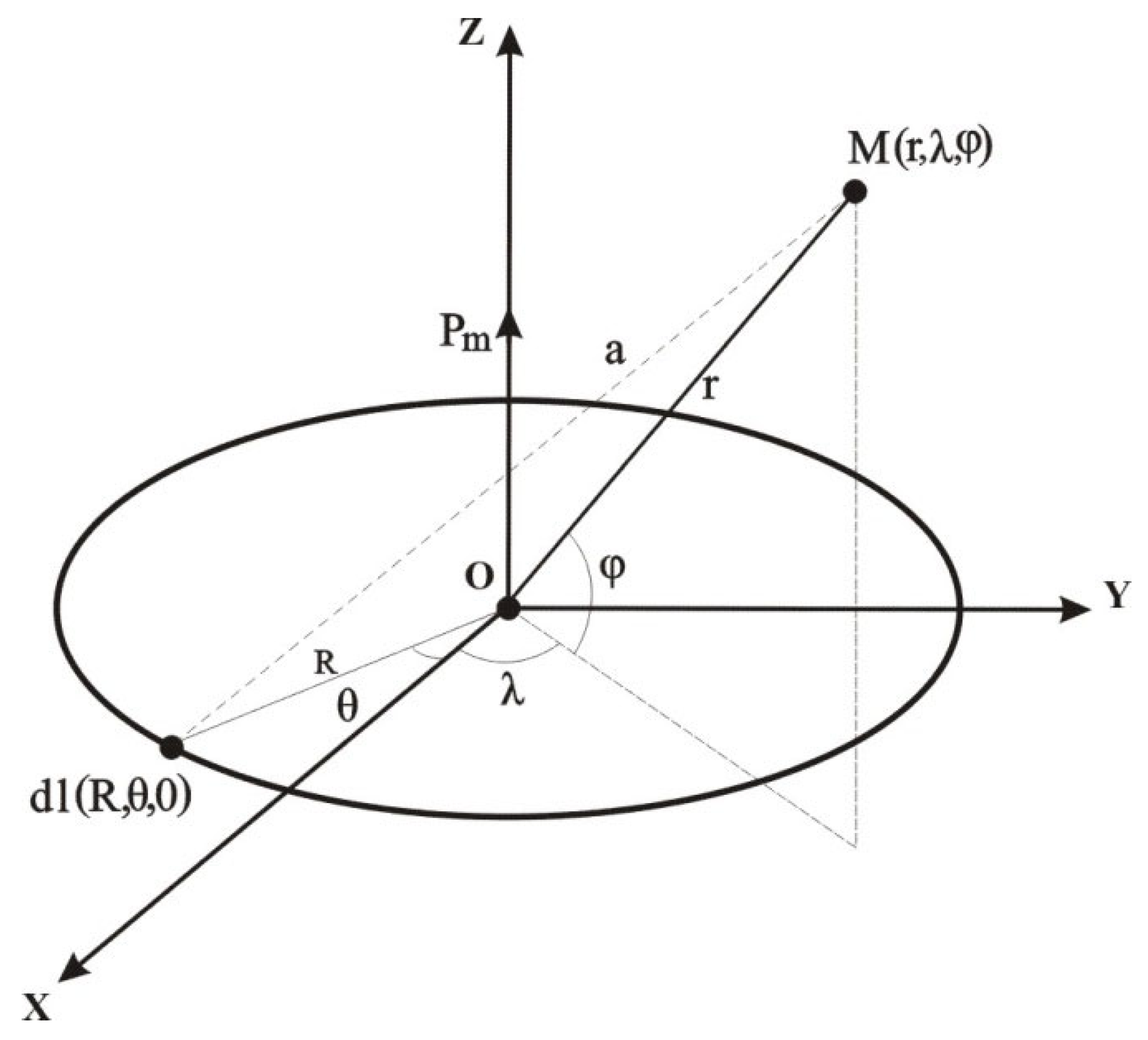
Figure 1. Graphical explanations of Formula (1).
Applsci 15 09633 g001
Figure 2. Intersection of planes.
Applsci 15 09633 g002aApplsci 15 09633 g002b
Figure 3. Transformation of the local coordinate system.
Applsci 15 09633 g003
Figure 4. Results of modeling the intersection points of the planes based on the results of measurements of the magnetic field on 23 October 2005: (a)—projection on the equator plane; (c)—projection on the plane of the zero meridian; (e)—projection on the plane of the meridian 90°, as well as the ring with a current of 0.5 Earth radius: (b)—projection on the equator plane; (d)—projection on the plane of the zero meridian; (f)—projection on the plane of the meridian 90°. The measurement units of all axes are represented in km.
Applsci 15 09633 g004
Table 1. Coordinates of the calculated intersection points of planes for Rring = 0.25REarth = 1595 km.
φ0(°)05102030405060
Δ(°)r/Δz
0.1r (km)43544408455450015459581760636221
Δz (km)0−10−76−519−1405−2567−3778−4856
1r (km)43554418457250235478583160736227
Δz (km)0−13−86−549−1453−2622−3830−4900
2r (km)43584431459250495500584760846235
Δz (km)0−16−98−584−1507−2684−3889−4948
5r (km)43764480466351335574590361256263
Δz (km)0−29−137−694−1671−2869−4065−5094
10r (km)44444595481152985718601762116328
Δz (km)0−57−215−891−1956−3185−4361−5338
15r (km)45594756500054965890615763216415
Δz (km)0−96−311−1109−2256−3509−4664−5586
20r (km)47274967523357296093632364556523
Δz (km)0−145−424−1349−2574−3847−4975−5841
Table 2. Coordinates of the calculated intersection points of planes for Rring = 0.5REarth = 3190 km.
φ0(°)05102030405060
Δ(°)r/Δz
0.1r (km)46754746493254325851611362566328
Δz (km)0−16−116−733−1809−3048−4206−5152
1r (km)46764759495354545867612362616331
Δz (km)0−20−131−773−1864−3103−4253−5189
2r (km)4679477649785481 5885613462686334
Δz (km)0−26−149−818−1924−3164−4306−5230
5r (km)47034838506355665947617462936350
Δz (km)0−45−207−958−2107−3347−4465−5352
10r (km)47904983523757316070625863516392
Δz (km)0−89−320−1204−2415−3652−4726−5553
15r (km)49375180545459256217636664306452
Δz (km)0−146−453−1465−2730−3957−4988−5755
20r (km)51515435571761526391649565276529
Δz (km)0−218−606−1744−3053−4267−5251−5958
Table 3. Coordinates of the calculated intersection points of planes for Rring = 0.9REarth = 5742 km.
φ0(°)05102030405060
Δ(°)r/Δz
0.1r (km)58506000621163736373635763546361
Δz (km)0−110−576−2021−3395−4458−5230−5767
1r (km)58526022622763766372635763546361
Δz (km)0−137−631−2088−3450−4499−5258−5786
2r (km)58616048624563806373635863566363
Δz (km)0−168−693−2161−3509−4543−5290−5808
5r (km)59166139630863996382636563626369
Δz (km)0−270−878−2374−3684−4674−5384−5872
10r (km)61006323643364546415639163846387
Δz (km)0−464−1188−2712−3960−4882−5534−5976
15r (km)63836544658465336468643264186414
Δz (km)0−678−1500−3034−4222−5080−5680−6078
20r (km)67636802676166336538648664606450
Δz (km)0−910−1813−3345−4473−5272−5822−6179
Table 4. Values of the ap index on 23 October 2005.
UTC0–33–66–99–1212–1515–1818–2121–24
ap42223330
Table 5. List of magnetic observatories whose data were used in modeling the magnetic field source.
Observatory 1Observatory 2Observatory 3
CodeLatitudeLongitudeCodeLatitudeLongitudeCodeLatitudeLongitude
1aaa43.2576.92nvs54.8583.23lzh36.09103.84
2abk68.3618.82ups59.9017.35bel51.8420.79
3aia−65.25295.74trw−43.27294.62pst−51.70302.11
4asc−7.95345.62vss−22.40316.35mbo14.39343.04
5asp−23.76133.88kdu−12.69132.47lrm−22.22114.10
6bdv49.0814.02fur48.1711.28mab50.305.68
7bel51.8420.79abk68.3618.82nur60.5124.66
8bfe55.6311.67mab50.305.68aqu42.3813.32
9blc64.32263.99fcc58.76265.91pbq55.28282.25
10bmt40.30116.20gzh23.97112.45kny31.42130.88
11bou40.14254.77dlr29.49259.08tuc32.17249.27
12box58.0738.23qsb33.8735.64sod67.3726.63
13brw71.32203.38cmo64.87212.14shu55.35199.54
14cbb69.12254.97res74.69265.11fcc58.76265.91
15clf48.022.26ebr40.960.33aqu42.3813.32
16cta−20.09146.26cnb−35.32149.36asp−23.76133.88
17dlr29.49259.08tuc32.17249.27fcc58.76265.91
18dou50.104.60ebr40.960.33fur48.1711.28
19ebr40.960.33spt39.55−4.35dou50.104.60
20esk55.31356.79dou50.104.60ebr40.960.33
21fcc58.76265.91pbq55.28282.25frd38.21282.63
22frn37.09240.28tuc32.17249.27new48.27242.88
23fur48.1711.28wng53.739.05bfe55.6311.67
24gck44.6320.77abk68.3618.82nur60.5124.66
25gdh69.25306.47naq61.17314.57sjg18.11293.85
26gui28.32343.56mbo14.39343.04sfs36.67354.06
27gzh23.97112.45lrm−22.22114.10phu21.03105.96
28had51.00355.52ler60.14358.82ebr40.960.33
29hbk−25.8827.71her−34.4319.23aae9.0438.77
30her−34.4319.23tsu−19.2017.58hbk−25.8827.71
31hrn77.0015.55ngk52.0712.68nck47.6316.72
32hua−12.05284.67sjg18.11293.85teo19.75260.82
33iqa63.75291.48thl77.47290.77gdh69.25306.47
34irt52.27104.45lzh36.09103.84nvs54.8583.23
35kak36.23140.19mmb43.91144.19gua13.59144.87
36kdu−12.69132.47asp−23.76133.88cta−20.09146.26
37kny31.42130.88kdu−12.69132.47kak36.23140.19
38kou5.21307.27sjg18.11293.85vss−22.40316.35
39ler60.14358.82had51.00355.52clf48.022.26
40lrm−22.22114.10kny31.42130.88kdu−12.69132.47
41lvv49.9023.75abk68.3618.82nur60.5124.66
42lzh36.09103.84irt52.27104.45gzh23.97112.45
43mab50.305.68clf48.022.26wng53.739.05
44mbo14.39343.04asc−7.95345.62kou5.21307.27
45mcq−54.50158.95sba−77.85166.76eyr−43.47172.39
46mmb43.91144.19kak36.23140.19kny31.42130.88
47naq61.17314.57stj47.59307.32gdh69.25306.47
48nck47.6316.72ngk52.0712.68ups59.9017.35
49new48.27242.88tuc32.17249.27mea54.62246.65
50ngk52.0712.68aqu42.3813.32fur48.1711.28
51nvs54.8583.23aaa43.2576.92irt52.27104.45
52paf−49.3570.26maw−67.6062.88czt−46.4351.86
53pbq55.28282.25fcc58.76265.91ott45.40284.45
54phu21.03105.96irt52.27104.45gzh23.97112.45
55ppt−17.57210.43hon21.32202.00frn37.09240.28
56res74.69265.11cbb69.12254.97blc64.32263.99
57sba−77.85166.76mcq−54.50158.95drv−66.67140.01
58sfs36.67354.06val51.93349.75had51.00355.52
59shu55.35199.54brw71.32203.38sit57.06224.67
60spt39.55−4.35had51.00355.52clf48.022.26
61stj47.59307.32kou5.21307.27sjg18.11293.85
62tan−18.9247.55hbk−25.8827.71czt−46.4351.86
63teo19.75260.82tuc32.17249.27bou40.14254.77
64thl77.47290.77iqa63.75291.48stj47.59307.32
65thy46.9017.89aqu42.3813.32gck44.6320.77
66tuc32.17249.27mea54.62246.65bou40.14254.77
67ups59.9017.35bfe55.6311.67aqu42.3813.32
68val51.93349.75sfs36.67354.06gui28.32343.56
69vic48.52236.58new48.27242.88frn37.09240.28
70wng53.739.05mab50.305.68fur48.1711.28
Table 6. Average r ¯ and root-mean-square σ Δ r values.
Rring0.05RE0.1RE0.15RE0.17RE0.2RE0.22RE0.25RE
Δ r ¯ 730727724723723723725
σ Δ r 650651653654657658662
Rring0.3RE0.4RE0.5RE0.6RE0.7RE0.8RE0.9RE
Δ r ¯ 7347899171154161620642295
σ Δ r 67270376490316022012912
Disclaimer/Publisher’s Note: The statements, opinions and data contained in all publications are solely those of the individual author(s) and contributor(s) and not of MDPI and/or the editor(s). MDPI and/or the editor(s) disclaim responsibility for any injury to people or property resulting from any ideas, methods, instructions or products referred to in the content.