Abstract
This paper presents a comprehensive study on the aerodynamic design, analytical modeling, and computational validation of shrouded rotor systems, encompassing both fixed-pitch and variable-pitch configurations in hover and forward flight. An analytical framework based on Blade Element Momentum Theory is developed and validated against Computational Fluid Dynamics simulations employing the Multiple Reference Frame method in ANSYS Fluent. A 16-inch shroud is designed through a four-step procedure considering tip clearance, the diffuser expansion ratio, and the inlet lip radius, and multiple rotor configurations are optimized using genetic algorithms. The results show strong agreement between analytical predictions and Computational Fluid Dynamics, with thrust predictions across operating conditions. In hover, variable-pitch rotors achieve comparable thrust–power performance to fixed-pitch rotors, despite requiring only a single optimized geometry; performance variations are achieved through pitch adjustment. In forward flight, variable-pitch rotors maintain high efficiency over a broader range of advance ratios, whereas fixed-pitch rotors exhibit peak efficiency only at a specific design point. These findings highlight the superior adaptability of variable-pitch rotors for missions requiring efficient operation across both hover and forward flight and demonstrate the reliability of the proposed analytical model as a rapid design tool.
1. Introduction
The spread of Unmanned Aerial Vehicles (UAVs) into applications near human environments has unveiled critical challenges in safety and noise pollution [1,2,3]. One promising mitigation strategy is the use of shrouds, which effectively reduce rotor noise, improve safety, and boost static performance. While such aerodynamic enhancements contribute to the traditional UAV development goals of performance and endurance optimization, they form part of a larger framework of concerns. This framework extensively includes the persistent and well-studied issues of operational safety, public security, and data privacy [4,5,6].
The performance of shrouded rotors is influenced by a wide range of parameters, including rotor geometry, aerodynamic coefficients, and operating conditions. These variables interact with other factors such as wind, ambient temperature, and altitude [7,8]. Additional parameters like the angle of attack, advance ratio, Reynolds number, Mach number, diffuser expansion ratio, diffuser angle, inlet lip radius, and rotor tip clearance have also been shown to significantly affect aerodynamic performance [9,10]. Reducing tip and root leakage by minimizing clearances and optimizing root radii improves pressure generation [11,12].
Optimizing shrouded rotor designs requires a careful integration of these variables. Past work has applied parametric analyses [7], optimization algorithms [13,14], and multi-objective approaches [15]. Understanding the aerodynamic behavior of shrouded rotors requires not only empirical data but also robust analytical tools that can predict performance across various flight conditions. As shrouded rotor configurations grow in complexity and application, particularly in Vertical Take-Off and Landing (VTOL) systems, the role of accurate and efficient modeling becomes increasingly vital.
Recent research has increasingly focused on the aerodynamic design and configuration analysis of shrouded rotors. Yu [16] employed both panel methods and Computational Fluid Dynamics (CFD) techniques to optimize shrouded rotor blades, demonstrating the effectiveness of hybrid computational approaches. Yilmaz et al. [17] conducted experimental studies to evaluate the performance and flow fields of shrouded rotors in both hovering and horizontal flight. Zhongyun et al. [18] adopted a propeller design method capable of determining the circulation distribution across the blade span, providing a foundation for improved aerodynamic efficiency. Guo [19] further advanced blade design methodology by modifying the classical blade element momentum theory using CFD results, thereby increasing the predictive accuracy for ducted fan performance.
1.1. Shrouded Rotor Analytical Modeling
Over the decades, a variety of methods have been developed to predict aerodynamic performance, ranging from classical momentum theory to modern semi-analytical and hybrid formulations. One of the earliest attempts to analytically describe ducted fan aerodynamics in forward flight was made by Kriebel [20], who extended potential flow methods to calculate forces and pitching moments for shrouded rotors in longitudinal flight. His work laid the foundation for modeling the effects of angle of attack in ducted configurations. Similarly, Ordway et al. [21] employed three-dimensional potential flow theory using vortex distributions and thin airfoil approximations, offering a Fourier series-based solution applicable to various configurations and enabling parametric studies of blade and duct parameters.
Simple analytical models offer cost-effective insights into shrouded rotor flows and can guide UAV design. One-dimensional momentum theory provides baseline thrust estimates but fails to incorporate shrouding effects. To address this, the Inlet Cap model was developed to extend momentum theory to shrouded rotors by introducing an imaginary inlet surface, but it still fails to account for blade shape or blade count effects [22].
Blade Element Theory (BET) can model sectional aerodynamic forces on each blade but requires accurate inflow data, which is hard to obtain in complex shrouded flows. Conversely, momentum theory estimates induced velocities but lacks geometric resolution. Combined Blade Element Momentum Theory (BEMT) merges the strengths of both approaches, allowing for detailed performance determinations across the rotor span. Bi et al. [23,24] proposed a hybrid model combining BET for rotor blades and a panel method for the duct, hub, and stators, enabling accurate performance estimation with mutual aerodynamic interaction.
Bontempo et al. advanced the modeling of ducted systems through a series of semi-analytical developments. They extended Conway’s actuator disk theory to ducted configurations [25], yielding exact solutions for axisymmetric incompressible flow with arbitrary duct geometries. Later works [26,27] incorporated vortex element methods and demonstrated the importance of duct–rotor thrust alignment and duct geometry, showing up to 15% performance improvements under optimal configurations. These low-cost models are especially useful for preliminary design and optimization.
Zhang et al. [28] presented a design methodology based on optimal circulation distribution and strip theory to derive blade geometry for ducted fans. Their simulations demonstrated up to 36% gains in power loading and hover efficiency compared to open rotor configurations, confirming the importance of integrated duct–blade optimization.
While significant progress has been made in optimizing fixed-pitch shrouded rotors, the integration of variable-pitch mechanisms within shrouds remains relatively underexplored. Variable-pitch rotors (VPRs) offer enhanced control authority and operational flexibility, particularly in varying flight regimes. However, incorporating pitch variation within a confined shroud environment introduces new aerodynamic and mechanical complexities. This motivates a focused investigation into the aerodynamic behavior and performance trade-offs of shrouded variable-pitch rotor systems.
1.2. Variable Pitch Rotors in Shrouded Configurations
Traditional open rotors typically control thrust by varying rotor speed, a method widely adopted in multi-rotor aircraft. However, combining RPM control with collective pitch adjustment, or even cyclic pitch for attitude control, offers improved responsiveness and aerodynamic efficiency [29,30], though such approaches demand advanced control allocation strategies and present challenges related to vibration and stability.
By adjusting blade pitch instead of relying solely on increased RPM, VPRs can reduce profile power consumption more effectively while maintaining performance, provided stall limits are not exceeded [31]. They also minimize control lag, as thrust modulation through pitch changes is significantly faster compared to the time required for motor speed adjustments. Furthermore, cyclic pitch enables compensation for edgewise flow-induced moments, improving stability and maneuverability in gusty or translational flight conditions [32,33]. Lastly, VPRs exhibit high adaptability, allowing blade angles to be optimized for varying flight regimes, from hovering to forward flight.
Early research into shrouded VPRs, such as Platt’s static tests, demonstrated nearly double the thrust of unshrouded rotors at equal power due to delayed stall and improved flow guidance [34]. Subsequent studies, including Gamse’s full-scale evaluations, confirmed efficiency gains but highlighted shroud drag as a key limitation [35]. Naval applications reported by Bi et al. [24] showed that ducts contribute up to 40% of total thrust in hover and 25% at moderate forward speeds, emphasizing the importance of optimized twist distribution and rotor–shroud positioning. Computational analyses by Lakshminarayan et al. [36] revealed that shrouds add 19–29% thrust in hover with minimal power penalty, while studies by Ye et al. [37] indicated that blade skewing in VPRs improves stall margins and efficiency.
Control-focused research also demonstrated that cyclic pitch improves roll stability in ducted UAVs under crosswinds and enhances gust rejection [38,39]. However, these benefits come with trade-offs such as increased sensitivity to lateral disturbances and higher parasitic drag.
Given these findings, VPR integration within shrouded configurations offers potential for significant improvements in efficiency, maneuverability, and responsiveness. Nonetheless, the aerodynamic interaction between shroud and VPR, particularly in forward flight, remains insufficiently explored and warrants further research to fully exploit this technology. Building on the motivation for improved rotor performance and control, the next step is to establish an analytical model that captures the unique aerodynamic characteristics of shrouded rotors, serving as the foundation for subsequent optimization and performance evaluations.
The rotor model developed in this work is intended as a generic representation of a shrouded rotor system rather than being tailored to a specific aircraft configuration. The selected rotor size and operating conditions correspond to small- to medium-scale UAV applications, where shrouded rotors are often employed for improved safety, efficiency, and noise reduction.
2. Analytical Model
The poorly understood aerodynamic behavior of shrouded rotors needs to be improved to enable better prediction and modeling of their performance. To enable tractable analysis, simplifying assumptions were adopted: blades are considered rigid and weightless, flow is steady and incompressible with ambient pressure , and effects such as dynamic stall and compressibility at high speeds are neglected.
The analytical framework begins by defining the inflow ratio for shrouded rotors in forward flight, which is then utilized within the BEMT to iteratively determine the induced velocity and overall rotor performance [40,41].
2.1. Forward Flight Regime Inflow Ratio
Previous research established an analytical expression for the inflow ratio of shrouded rotors in hover, which was validated using both CFD simulations and experimental measurements [42]. In forward flight, however, the aerodynamic role of the shroud changes: as the flight speed increases, the shroud’s contribution transitions from augmenting thrust to producing drag. The analytical model developed in this study does not account for the shroud’s thrust or drag in forward flight. Moreover, the objective of this work is not to optimize the shroud design itself, but rather to focus on rotor performance modeling and comparison between fixed- and variable-pitch configurations.
Shrouded rotors operating in forward flight exhibit a different inflow ratio compared to hover. In this study, forward flight is modeled under the assumption of axisymmetric, uniform inflow across the rotor disk. This assumption is appropriate for axial forward flight conditions with negligible sideslip, where azimuthal variations in inflow are minimal. Figure 1 illustrates the shrouded rotor configuration in forward flight, assuming that the velocity and static pressure at station 1 are equal to those at station 0 ( and , respectively).
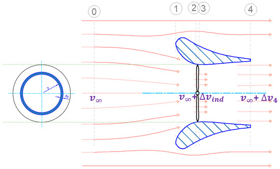
Figure 1.
Shrouded rotor stations in forward flight.
Applying the continuity equation between stations 3 and 4, Equation (1) is obtained:
where and represent the velocity increments relative to the free-stream velocity at the rotor plane and at the shroud exit plane, respectively. Here, denotes the area of the rotor disc plane, while corresponds to the shroud exit plane area.
By applying the conservation of momentum equation between just before and just after the rotor (i.e., from station 2 to station 3), the rotor thrust can be calculated as per Equation (3).
where is the static pressure just before the rotor, as given in Equation (4), and is the static pressure just after the rotor, as shown in Equation (5).
By substituting for static pressure values from Equations (4) and (5) in Equation (3), the rotor thrust can be found according to Equation (6).
By substituting from Equation (2) into Equation (6), the rotor thrust expression in Equation (7) is obtained as follows:
where is the expansion ratio of the shroud (). By rearranging, Equation (8) is obtained.
The area of the rotor annular blade element of interest at radial position y can be found as . Thus, the elementary rotor thrust can be found as per Equation (9).
where is the shrouded rotor tip and root loss correction factor, as calculated in Equation (10) [42].
where and are the root loss factor (Equation (11)) and the tip gap loss factor (Equation (13)), respectively.
where
The parameter K in Equation (13) is the complete elliptic integral of the first kind, and is the inverse of the Jacobi elliptic function. In the present modeling framework, the elliptic integral of the first kind is evaluated using MATLAB’s (R2024b) built-in function ellipticK. The complete elliptic integral modulus is defined as , where f and g are defined in Equation (14) and Equation (15), respectively.
The term , in Equation (15), is the tip gap clearance (the distance between the shroud’s inner walls and the rotor tip). The elementary rotor thrust coefficient can be found as per Equation (16).
where r is the nondimensional radius (), R is the rotor radius, is the rotor rotational velocity, is the rotor advance ratio (), and is the local increase in inflow ratio relative to the free stream velocity ().
As one of the blade element theory findings, the elementary rotor thrust coefficient can be obtained as follows [33,43]:
where is the local element pitch angle, () is the solidity ratio of the rotor, and is lift curve slope of the local cross-sectional airfoil. By equating Equations (16) and (17), a quadratic function of the inflow ratio for the shrouded rotor can be obtained (Equation (18)).
This is rearranged to be
Solving the equation yields the local increment in inflow ratio relative to the free stream velocity for the shrouded rotor case. The negative root is physically inadmissible and thus neglected, resulting in Equation (20).
By rearranging, Equation (21) is obtained for the local inflow ratio.
In hovering flight, the free stream velocity is zero (), so by substituting for in Equation (21), the inflow ratio in the case of hovering flight is obtained [42].
2.2. BEMT
Considering the local velocities on a blade element (shown in Figure 2), the tangential velocity, , arises from the blade’s rotational motion (Equation (23)). The perpendicular velocity, , is formed by the free stream velocity and the induced velocity at the blade element, as calculated using Equation (24).
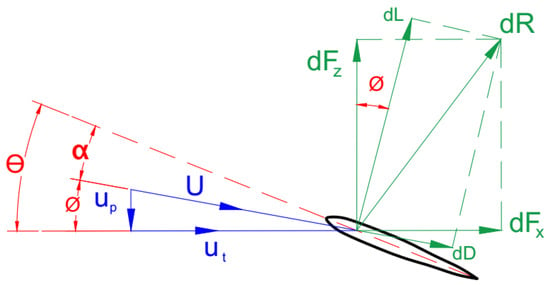
Figure 2.
Aerodynamic forces and angles on the blade element.
The relative elementary angle of attack can be written as
where is the local twist angle. Based on the value of the calculated local values of the angle of attack, Reynolds number, and cross-sectional airfoil type, the corresponding local lift coefficient, drag coefficient, and lift curve slope are obtained. So, the elementary lift, , and drag, , per unit span on the corresponding blade element can be then described by resolving the lift and drag forces into parallel and normal components relative to the rotor disk.
Therefore, the elementary thrust, torque, and power of the disk can be defined and by integrating them radially and azimuthally for all blades, , the rotor’s average thrust, torque, and power can be obtained, as represented by Equation (26), Equation (27), and Equation (28), respectively.
where is the air density, is the cut-off radius, c is the local chord, U is the resultant total velocity, , is the inflow angle, and and are the lift and drag coefficients respectively, both obtained for each section of the rotor blade according to the sectional airfoil characteristics. The total thrust, in the case of hovering, can be calculated as per Equation (29) according to the inlet cap model [22,42].
where is the inlet ratio (), and is the inlet cap ratio (). To improve the accuracy of performance predictions for shrouded rotor systems, a post-stall model is incorporated to account for nonlinear aerodynamic behavior at high angles of attack, ensuring robust performance predictions across a wider operating envelope [42].
A shroud was designed to match the 16-inch rotor used in this research, ensuring consistent geometry for both analytical modeling and computational validation.
3. Design of the 16-inch Shroud
The shroud design process, based on four primary steps, is illustrated in Figure 3. The design emphasizes several critical geometric and aerodynamic factors, including rotor tip clearance, transition length, the diffuser expansion ratio, and inlet lip shape.
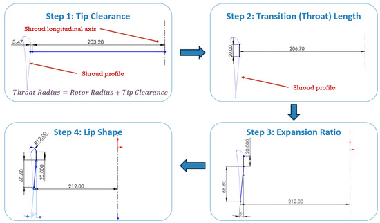
Figure 3.
16-inch shroud design steps (all dimensions in mm).
It is important to clarify that the present research does not aim to develop advanced shroud design methodologies. Instead, the goal is to establish a shroud geometry that is sufficiently effective for this research, without claiming optimal performance beyond meeting the analytical and simulation requirements.
- Step 1:
- Tip clearance selection (): Tip clearance is a critical performance factor, and it has been demonstrated that reducing it from 3.04% to 1.71% of the rotor radius can increase the hover efficiency of the shrouded rotor system by 17.85%. Conversely, increasing the tip clearance from 3.04% to 5.17% of the rotor radius can lead to a significant reduction in hover efficiency of up to 18.1%, even falling below the performance of an open rotor configuration [44].
The design process begins with selecting an appropriate tip clearance value, which is added to the rotor radius to determine the shroud’s throat section. For the 16-inch radius (203.2 mm) rotor, a tip clearance equal to 1.71% of the rotor radius is selected, corresponding to 3.47 mm. Adding this clearance to the rotor radius yields an inner radius of 206.7 mm at the shroud’s throat.
- Step 2:
- Defining Transition length: Cao et al. [45] demonstrated that extending the shroud’s transition length can slightly enhance hovering efficiency, as measured by the figure of merit. However, the improvement tends to diminish at significantly greater lengths. The throat (transition) length of the 16-inch shroud is set to 20 mm, providing a strong geometric match between the rotor tip chord and its pitch angle. Additionally, the selected transition length contributes to maintaining a minimal overall shroud chord, which is essential for preserving the shroud’s primary function of reducing drag during forward flight operations. Furthermore, the selected transition length helps maintain a constant tip clearance between the blade tips and the shroud wall, particularly when analyzing variable-pitch rotors at high collective pitch angles.
- Step 3:
- Selecting the Expansion Ratio and Diffuser Length: Among the parameters influencing shrouded rotor performance, the expansion ratio is theoretically considered to have the most significant impact [46]. It is regarded as the primary contributor to the efficiency gains observed in comparison to open rotor configurations. However, experimental improvements are often significantly smaller than those predicted by theoretical models, with reported performance gains varying considerably across different studies [47].
Misiorowski et al. [48] conducted a computational study on the effects of diffuser length, examining configurations ranging from 18% to 144% of the rotor radius. Their hover performance analysis of shrouded rotors revealed that shorter diffusers (e.g., 18% R) produced approximately 3% less thrust and required 1.5% more power compared to longer configurations (e.g., 144% R). Despite these observations, their study showed that all shrouded configurations significantly outperform open rotors, delivering approximately range2630% greater thrust.
Based on these findings, a moderate diffuser angle of 5° was selected to mitigate the risk of flow separation along the shroud’s inner walls, which corresponds to an expansion ratio of . This choice, combined with a compact diffuser length of 68.6 mm (34% R), enables a reduction in the overall shroud chord and camber, thereby minimizing aerodynamic drag during forward flight.
- Step 4:
- Defining Lip Shape: A properly sized lip helps to guide incoming flow smoothly into the duct, minimizing separation and reducing inlet losses. Based on the available literature, the recommended lip radius typically falls within the range of 3% to 15% of the rotor diameter [49,50], providing notable aerodynamic benefits from shrouding, particularly under static conditions.
Following these recommendations, and to minimize the shroud’s cross-sectional thickness and aerodynamic interference during forward flight, the 16-inch design adopts a lip radius equal to 3% of the rotor diameter, corresponding to 12 mm. This relatively small lip radius results in a thin shroud profile, helping to reduce aerodynamic drag at higher forward flight speeds.
From the above-described shroud design process, the resulting profile for the 16-inch shroud is shown in Figure 4, which also incorporates a smooth external wall contour to further reduce aerodynamic drag during forward flight.
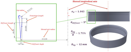
Figure 4.
Final 16-inch shroud profile and its geometric parameters (all dimensions in mm).
4. CFD Model Setup
The CFD model incorporates appropriate boundary conditions and turbulence modeling strategies to accurately capture the flow physics of the shrouded rotor. ANSYS (2024 R1) FLUENT CFD software was used to perform the simulations, employing the Multiple Reference Frame (MRF) method to model rotor rotation in a steady-state environment. The computational domain is divided into two sub-domains: (i) a stationary domain, defined as a cylindrical volume with a length of 2500 mm and a diameter of 2000 mm, encompassing the entire simulated experimental setup and (ii) a rotating domain surrounding the rotor, as shown in Figure 5. A velocity inlet is specified at the inlet boundary, while a pressure outlet is applied at the outlet, and all surfaces are treated as no-slip walls.
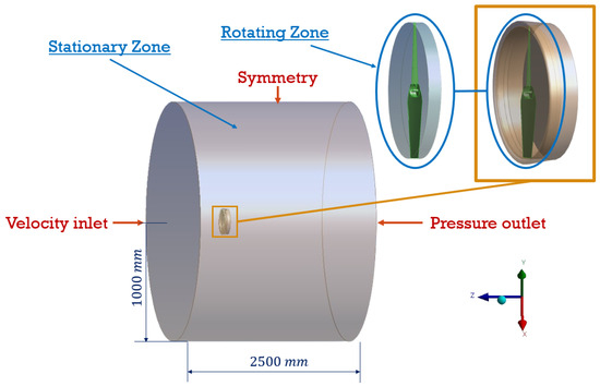
Figure 5.
Stationary and rotating zones used in the simulation.
To conduct the CFD simulations, the Realizable k– turbulence model was employed due to its proven effectiveness in modeling rotating flows with complex vortex structures. This model provides a favorable compromise between computational efficiency and accuracy, particularly in capturing critical aerodynamic behaviors such as boundary layer separation and vortex shedding [51,52,53].
Each simulation was executed for 5000 iterations to ensure convergence to a steady-state solution. Convergence was assessed by monitoring the residuals, ensuring they fell below , and stabilizing thrust and torque outputs. A summary of the simulation setup is presented in Table 1.

Table 1.
ANSYS Fluent CFD simulation setup.
Equations (30) and (31) present the mathematical expressions for turbulent kinetic energy (k) and turbulent dissipation rate (), respectively.
In contrast to the standard k– model, the Realizable formulation introduces a key modification by treating as a variable rather than a constant in the turbulent viscosity calculation. The turbulent viscosity is computed as , where is evaluated using the following expression:
This modification enhances the Realizable k– model’s capability to simulate turbulent flows with rotational effects more accurately, making it especially well suited for rotor aerodynamics. It effectively captures complex flow features such as recirculation zones and boundary layer separation [54,55].
5. Optimized Rotors
To systematically explore the aerodynamic performance of shrouded rotors, a structured optimization framework was implemented for both hover and forward flight regimes. Table 2 summarizes the key design parameters, constraints, and objectives employed in each case. This research includes fixed-pitch (16A, 16B, 16C, FP F15, and FP F30) and variable-pitch (V16A, V16B, V16C, VP F15, and VP F30) configurations. Design variables include chord distribution (), twist distribution (), and, for variable-pitch rotors, the collective pitch angle (). Hover optimizations impose thrust constraints ( N or N), while forward flight optimizations rely on geometric bounds. Fixed-pitch rotors have 12 design variables (6 , 6 ), whereas variable-pitch rotors have 11 (5 , 5 , and ).

Table 2.
Summary of optimization parameters for shrouded rotors.
The VPR blade is divided into five radial segments, extending from the root cut-off radius of 45 mm to the tip. In contrast, the fixed-pitch rotor (FPR) blade is discretized into six radial elements, beginning at a smaller root cut-off radius of 22 mm. The difference in the number of elements is therefore a direct result of the different cut-off radii chosen for each configuration, which determine the spanwise region available for optimization.
Optimization was conducted using MATLAB’s Genetic Algorithm (GA) implementation available in the Global Optimization Toolbox. The default GA settings were employed, including automatic population scaling, a crossover fraction of 0.8, adaptive feasible mutation, and stochastic uniform selection. These default parameters proved sufficient to achieve convergence across all rotor design cases—after a few repeated runs—thereby eliminating the need for manual tuning or customization of the algorithm settings.
5.1. Hovering Rotor Optimization
For hovering rotors, the optimization objective is to maximize aerodynamic efficiency, defined as the thrust-to-power ratio:
where represents the vector of design variables (chord and twist values) for fixed-pitch rotors in hovering.
The rotor blade is divided into six radial sections (from a root cut-off radius of 22 mm to the tip), each defined by chord length and twist angle , giving 12 total design variables:
To ensure torque remains within the manufacturer’s suggested operating range of the BLDC motor, the design bounds are
5.1.1. Fixed-Pitch Rotors: 16A–16C
Three fixed-pitch rotors were optimized at an RPM of 3000:
- 16A: Baseline rotor with only geometric bounds.
- 16B: Includes a thrust constraint ( N).
- 16C: Designed for a higher thrust requirement ( N).
The penalty function used is
where and or 11 N for 16B and 16C, respectively.
Figure 6 shows the optimized chord and twist distributions for Rotors 16A, 16B, and 16C. The comparison demonstrates how increasing the thrust requirement drives significant changes in blade geometry. This analysis underscores the principal limitation of fixed-pitch rotor systems: any change in operational regime requires a full re-optimization of the rotor geometry.
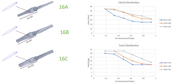
Figure 6.
Rotors 16A, 16B, and 16C chord and twist distributions.
5.1.2. Variable-Pitch Rotors: V16A–V16C
The same approach is applied to variable-pitch rotors in hover, and the objective function is the same as fixed-pitch rotors, but with 11 design variables:
where (collective pitch) is an additional global variable. The bounds are
V16B and V16C include the same thrust penalties as 16B and 16C. While the chord and twist distributions converge to nearly identical shapes across V16A–C, the optimal increases with thrust: 18.7°, 23.7°, and 27.9° for V16A, V16B, and V16C, respectively (Figure 7).
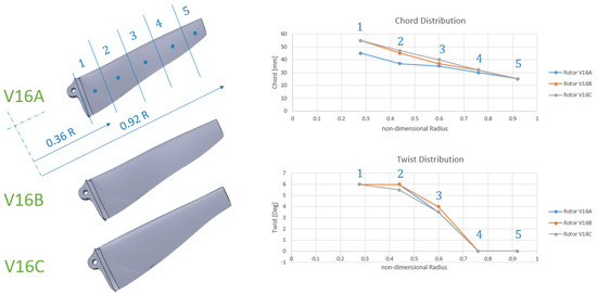
Figure 7.
Chord and twist distributions for V16A, V16B, and V16C.
This highlights the flexibility of variable-pitch rotors in hover, which can adjust performance through , unlike fixed-pitch rotors that require full re-optimization.
5.2. Forward Flight Rotor Optimization
The forward flight optimization follows a similar framework but accounts for higher inflow angles. Two fixed-pitch (FP F15 and FP F30) and two variable-pitch (VP F15 and VP F30) rotors are optimized for forward speeds of 15 m/s and 30 m/s.
The objective function is
where includes chord and twist distributions for fixed-pitch rotors in the forward flight regime, in which rotors experience higher inflow angles, so the bounds are expanded to
Figure 8 shows that FP F30 exhibits larger chord and twist angles compared to FP F15, reflecting the increased aerodynamic loads at higher speeds.
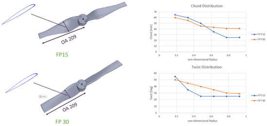
Figure 8.
Chord and twist distributions for FP F15 and FP F30.
For variable-pitch rotors, the objective function is the same as that of fixed-pitch rotors in forward flight, and the design variable vector in forward flight is
with bounds extended to
Figure 9 compares the optimized variable-pitch rotors for 15 m/s (VP F15) and 30 m/s (VP F30) forward flight conditions. Unlike the hovering regime, the geometries of these forward flight rotors differ significantly. Nevertheless, a common trend observed in both fixed- and variable-pitch configurations is the requirement for increased blade twist at higher forward flight speeds.
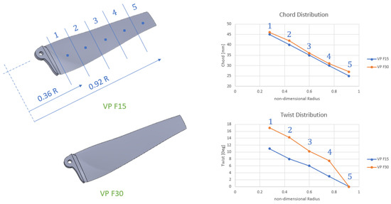
Figure 9.
Chord and twist distributions for VP F15 and VP F30.
As expected, the optimal collective pitch angle increases with forward speed, reaching for VP F15 and for P F15, respectively.
6. Results and Discussion
In this section, the results of CFD simulations for optimized fixed- and variable-pitch shrouded rotors in the hovering regime are presented. This is followed by the validation of the analytical model in forward flight, after which the performance of the optimized fixed- and variable-pitch shrouded rotors for that regime is compared.
To verify that the computational results were independent of spatial discretization, a grid convergence study was carried out. Figure 10 shows the convergence of thrust and torque at 4000RPM for both hover and forward flight at 15 m/s. In both cases, the solutions stabilize as the mesh resolution increases, and the asymptotic behavior confirms that the finest grid tested is sufficiently refined. Further refinement produced no significant changes, establishing the grid independence of the reported results.
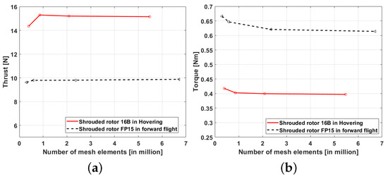
Figure 10.
Grid dependency study results. (a) Total thrust convergence; (b) Torque convergence.
6.1. Hovering Optimized FPR vs. VPR CFD Results
The reason for optimizing three rotors for each case of fixed- and variable-pitch configurations is to demonstrate the ability of VPRs to maintain optimal performance across different thrust requirements by adjusting the collective pitch angle, unlike FPRs. In this section, rotor V16B is simulated at two different collective pitch angles and compared against the other two FPRs (16A and 16B) to better understand the resulting performance differences.
Variable-pitch rotor V16B at a collective pitch angle of and fixed-pitch rotor 16A exhibit higher total thrust-to-power ratios (Figure 11a). This is primarily because FP 16A was optimized without a thrust constraint (i.e., no penalty function) at the design condition of 3000 RPM. On the other hand, V16B at operates slightly off its design-point thrust constraint, which results in a high thrust-to-power ratio and low thrust value, as shown in Figure 11b. VPR V16B at a collective pitch angle of and FPR 16B exhibit lower total thrust-to-power ratios compared to the previous two rotors, which is again attributed to the enforcement of the thrust constraint at the design point.
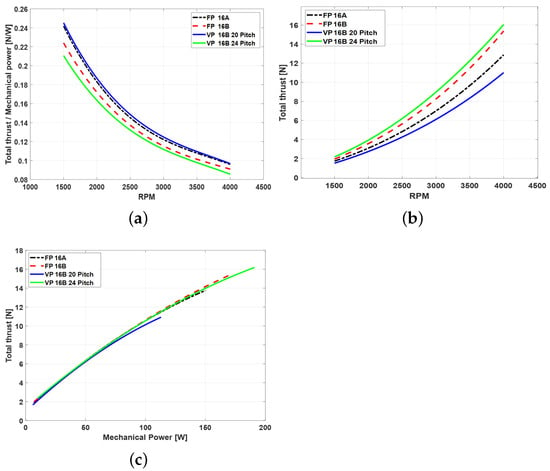
Figure 11.
Performance of 16A, 16B compared to V16B at two pitch angles of 20° and 24°. (a) Total thrust to power ratio vs. RPM. (b) Total thrust vs. RPM. (c) Total thrust vs. mechanical power.
The thrust versus mechanical power trends, illustrated in Figure 11c, reveal consistent performance behavior across all rotor configurations. In the hovering regime, the optimization process resulted in all rotor designs achieving comparable performance in terms of generating the required thrust for a given mechanical power input for both fixed- and variable-pitch rotors. This indicates that the optimization was effective in balancing aerodynamic loading and power consumption across different rotor types, leading to similar efficiency levels under hover conditions.
6.2. Analytical Model Validation in Forward Flight
This section presents a comparison between the results obtained from the proposed analytical model and the CFD simulations for forward flight conditions. The primary purpose of this comparison is to validate that the analytical model can replicate the aerodynamic performance of the shrouded rotor across a range of advance ratios. The advance ratio is defined as the ratio of freestream velocity to the product of rotational speed and rotor radius, indicating how effectively a rotor performs in forward flight. The validation is conducted only for the forward flight regime, as the hovering regime was previously validated and established [42].
In the validation process, only the rotor thrust and torque were considered, as the analytical model does not account for the aerodynamic forces acting on the shroud. In contrast, the CFD simulations capture the full flow field, including the contributions of shroud thrust and drag. Therefore, the comparison focuses solely on rotor-induced forces to ensure consistency between the two models.
In the CFD simulations, the rotor forces were extracted separately from the shroud by integrating the pressure and viscous loads acting only on the rotor blade surfaces. This was achieved in ANSYS Fluent using surface-based force reports. The net aerodynamic force was calculated along the longitudinal axis, opposite to the incoming flow direction, corresponding to the thrust-producing component. This procedure ensured that only rotor forces were reported, excluding any contributions from the shroud or surrounding surfaces, thereby enabling a direct comparison with the analytical model.
The comparison between the CFD and analytical results in Figure 12 shows that the analytical model tends to slightly overestimate both rotor thrust and torque at low to moderate advance ratios, which is expected due to the simplifying assumptions inherent in the model. In particular, viscous and compressibility effects are ignored in the analytical model, leading to discrepancies that become more noticeable as the advance ratio increases.
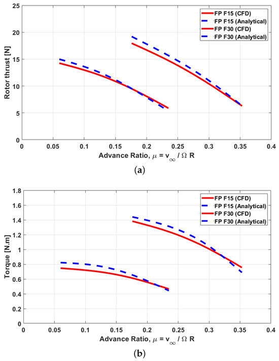
Figure 12.
Computational vs. analytical results for shrouded rotor in forward flight regime. (a) Rotor thrust. (b) Torque.
It is important to recognize the limitations of the MRF method used in the CFD simulations. The MRF approach is straightforward to implement, well suited for steady-state problems, and relatively inexpensive in terms of computational cost. However, it cannot capture unsteady flow phenomena such as wake interactions or vortex shedding. The method is most reliable when the flow entering the rotating domain is predominantly axial and uniform, conditions that facilitate the transition between stationary and rotating reference frames [56,57]. Within the applicable range, the MRF method provides a reasonable balance between accuracy and efficiency, making it appropriate for validation against the analytical model.
At higher advance ratios, larger discrepancies emerge between the analytical predictions and the CFD results. These deviations stem from the analytical model’s inability to fully represent the complex rotor–shroud interactions that intensify with forward speed. Specifically, boundary-layer growth and flow separation at the shroud inlet lip alter the inflow distribution along the rotor span, while the analytical formulation assumes attached flow and simplified momentum exchange. Under these conditions, the rotor blades operate at near-zero local angles of attack, making the results highly sensitive to even minor deviations in the predicted inflow angle. For example, if CFD resolves a slightly positive inflow angle at a blade element, the analytical model may approximate it as zero or negative, leading to an underprediction of thrust and power. This analysis highlights that the analytical model becomes less reliable at advance ratios where the local blade angle of attack approaches zero.
Overall, the model demonstrates reliable predictive capability across a range of flight regimes, establishing its value as a practical tool for preliminary design and performance estimation.
6.3. CFD Simulation Results of Optimized VPR vs. FPR in Forward Flight
This section evaluates shrouded rotor performance through systematic comparison of fixed- and variable-pitch configurations at two design forward speeds (15 m/s and 30 m/s).
6.4. 15 m/s Forward Speed
Figure 13 illustrates the propulsive efficiency () versus advance ratio () characteristics for a shrouded rotor system. The analysis of performance across varying advance ratios highlights the substantial benefits of employing variable-pitch configurations in shrouded rotor systems. While the fixed-pitch design (FP F15) exhibits an efficiency peak near followed by degradation, the variable-pitch rotors demonstrate more adaptable behavior. Low pitch angles to excel at low advance ratios, whereas higher angles ( and ) sustain performance at higher flight speeds.
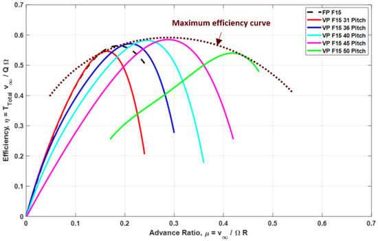
Figure 13.
Rotor FP F15 and VP F15 performance in forward flight regime.
These trends underline the superior versatility of variable-pitch rotors, enabling extended, efficient operating envelopes, adaptive aerodynamic response, and improved suitability for VTOL aircraft. By dynamically tuning the blade pitch, variable-pitch systems effectively bridge the performance gap between hover and forward flight, offering a compelling solution for next-generation aerial vehicles.
6.5. 30 m/s Forward Speed
Figure 14 presents the propulsive efficiency characteristics versus advance ratio () for both FP F30 and VP F30 rotor configurations in forward flight. As with lower forward speeds, the results confirm the advantage of variable-pitch systems in extending aerodynamic efficiency across a wider range of operating conditions.
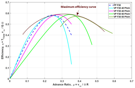
Figure 14.
Rotor FP F30 and VP F30 performance in forward flight regime.
While the FPR (FP F30) reaches its peak efficiency at an advance ratio of and experiences a decline beyond that point, VPRs (VP F30) maintain favorable performance through adaptive pitch control. Specifically, lower pitch settings deliver strong efficiency at low , while higher pitch angles sustain performance at elevated values, with the overall efficiency envelope spanning to . These findings underscore the suitability of variable-pitch configurations for missions requiring efficient operation over a broad speed spectrum, particularly in high-speed regimes.
7. Conclusions
This research successfully validates the analytical model for predicting the performance of a shrouded rotor in forward flight, demonstrating high accuracy and complementing the authors’ previous work in hover. The derived inflow ratio formulation for forward flight proved to be both reliable and effective, as evidenced by the strong agreement between analytical predictions of rotor thrust and CFD results.
The design and implementation of a 16-inch shroud were discussed in detail, with specific attention to geometric parameters influencing performance, such as tip clearance, diffuser geometry, and lip radius. A systematic optimization framework was developed to compare fixed-pitch and variable-pitch shrouded rotors at two design speeds (15 m/s and 30 m/s). The results highlight the superior adaptability of variable-pitch rotors, which maintained high efficiency at larger advance ratios and exhibited a wider efficient operating range than the fixed-pitch designs.
CFD simulations confirmed that optimized variable-pitch rotors offer comparable thrust performance to fixed-pitch rotors in hover, while enabling improved efficiency and a broader operational envelope in forward flight. In hovering, optimization led to distinct chord and twist distributions for fixed-pitch rotors, reflecting varying thrust requirements. Conversely, variable-pitch rotors displayed nearly identical geometries, with performance variations achieved primarily through adjustments to the optimal collective pitch angle. The thrust generated for a given mechanical power in hover showed consistent performance trends for both FPR and VPR configurations, achieving comparable performance.
For forward flight, both fixed-pitch rotors and variable-pitch rotors required unique geometries for different flight speeds. For both geometries, higher forward speeds demanded increased blade twist for both configurations. The CFD simulation results highlight the suitability of VPRs for missions requiring efficient operation over a broad speed spectrum, particularly at higher forward speeds. In contrast, fixed-pitch rotors achieve peak efficiency only at a specific advance ratio.
These results highlight the potential of variable-pitch control for enhancing the aerodynamic efficiency and mission flexibility of shrouded rotorcraft, particularly in applications requiring frequent transitions between hover and forward flight. The validated analytical model further provides a practical and computationally efficient tool for the early-stage design and optimization of such systems.
The proposed analytical framework can be extended to account for non-axial inflow conditions, unsteady rotor–shroud interactions, and dynamic inflow effects, which become increasingly relevant in maneuvering flight. This highlights the potential for the further development of the method to support a more comprehensive and mission-oriented optimization of shrouded rotor systems.
Author Contributions
Methodology, A.D. and R.J.M.; Software, A.D.; Formal Analysis, A.R.-S.; Writing—Original Draft, A.D.; Writing—Review and Editing, A.R.-S. and R.J.M.; Supervision, A.R.-S. and R.J.M. All authors have read and agreed to the published version of the manuscript.
Funding
This research received no external funding.
Data Availability Statement
The original contributions presented in this study are included in the article. Further inquiries can be directed to the corresponding author.
Conflicts of Interest
The authors declare no conflicts of interest.
Nomenclature
| Roman Symbols | |
| Rotor disc area | |
| c | chord length |
| Elementary radius (element thickness) | |
| Elementary thrust coefficient of shrouded rotor | |
| Elementary drag force coefficient | |
| Elementary lift force coefficient | |
| Elementary lift force coefficient | |
| Elementary non-dimensional rotor radius | |
| Elementary rotor thrust | |
| Shrouded rotor tip and root loss correction factor | |
| Inlet ratio | |
| Inlet cap ratio | |
| Rotor number of blades | |
| Average power of shrouded rotor | |
| p | Pressure |
| Average torque of shrouded rotor | |
| R | Rotor radius |
| r | Non-dimensional rotor radius |
| Root cutout radius | |
| Average thrust of the rotor | |
| Rotor thrust | |
| Total thrust of shrouded rotor | |
| U | Resultant velocity on blade section due to blade motion |
| , , | Tangential, perpendicular and radial velocity components, respectively |
| The induced velocity (velocity increment at rotor disc plane relative to the | |
| free-stream velocity) | |
| Freestream velocity | |
| y | radial position |
| Greek Symbols | |
| Relative angle of attack | |
| Velocity increment at shroud exit plane relative to the free-stream velocity | |
| Inflow angle | |
| Pitch angle | |
| Collective pitch angle | |
| Twist pitch angle | |
| Rotor solidity ratio | |
| Expansion ration | |
| Air density, () | |
| Inflow ratio | |
| Advance ratio | |
| Angular velocity of rotor blade () | |
| Acronyms | |
| Angle of Attack | |
| Blade Element Theory | |
| Computational Fluid Dynamics | |
| Fixed-Pitch Rotor | |
| Multiple Reference Frame | |
| Revolution per minute | |
| Unmanned Aerial Vehicles | |
| Variable-Pitch Rotor | |
| Vertical Takeoff and Landing | |
References
- Ghommam, J.; Saad, M.; Wright, S.; Zhu, Q.M. Relay manoeuvre based fixed-time synchronized tracking control for UAV transport system. Aerosp. Sci. Technol. 2020, 103, 105887. [Google Scholar] [CrossRef]
- Bu, H.; Wu, H.; Bertin, C.; Fang, Y.; Zhong, S. Aerodynamic and acoustic measurements of dual small-scale propellers. J. Sound Vib. 2021, 511, 116330. [Google Scholar] [CrossRef]
- End, A.; Barzantny, C.; Stolz, M.; Grupe, P.; Schmidt, R.; Papenfuß, A.; Eißfeldt, H. Public acceptance of civilian drones and air taxis in Germany: A comprehensive overview. CEAS Aeronaut. J. 2025. [Google Scholar] [CrossRef]
- Wild, G.; Murray, J.; Baxter, G. Exploring civil drone accidents and incidents to help prevent potential air disasters. Aerospace 2016, 3, 22. [Google Scholar] [CrossRef]
- Kloet, N.; Watkins, S.; Wang, X.; Prudden, S.; Clothier, R.; Palmer, J. Drone on: A preliminary investigation of the acoustic impact of unmanned aircraft systems (UAS). In Proceedings of the 24th International Congress on Sound and Vibration, London, UK, 23–27 July 2017; p. 8. [Google Scholar]
- Del Duchetto, F.; Pagliaroli, T.; Candeloro, P.; Rossignol, K.S.; Yin, J. Aeroacoustic study of synchronized rotors. Aerospace 2025, 12, 162. [Google Scholar] [CrossRef]
- D’Angelo, S.; Berardi, F.; Minisci, E. Aerodynamic performances of propellers with parametric considerations on the optimal design. Aeronaut. J. 2002, 106, 313–320. [Google Scholar] [CrossRef]
- Ma, R.; Zhong, B.; Liu, P.; Drikakis, D. Multi-objective optimization design of low-Reynolds-number airfoils S1223. In Proceedings of the 27th International Congress of the Aeronautical Sciences, Nice, France, 19–24 September 2010; pp. 1–10. [Google Scholar]
- Zhang, T.; Barakos, G.N. Review on ducted fans for compound rotorcraft. Aeronaut. J. 2020, 124, 941–974. [Google Scholar] [CrossRef]
- Zhao, Y.; Tian, Y.; Wan, Z. Aerodynamic Characteristics of a Ducted Fan Hovering and Transition in Ground Effect. Aerospace 2022, 9, 572. [Google Scholar] [CrossRef]
- Akturk, A.; Camci, C. Tip Clearance Investigation of a Ducted Fan Used in VTOL UAVS: Part 1—Baseline Experiments and Computational Validation. In Proceedings of the Turbo Expo: Power for Land, Sea, and Air, Vancouver, BC, Canada, 6–10 June 2011; Volume 54679, pp. 331–344. [Google Scholar]
- Akturk, A.; Camci, C. A Computational and Experimental Analysis of a Ducted Fan Used in VTOL UAV Systems; Department of Aerospace Engineering, Pennsylvania University: Philadelphia, PA, USA, 2011. [Google Scholar]
- Stahlhut, C.W. Aerodynamic Design Optimization of Proprotors for Convertible-Rotor Concepts; University of Maryland: College Park, MD, USA, 2012. [Google Scholar]
- Pastor, G. Propeller Design and Optimization Using a Robust Genetic Algorithm and a Computationally Efficient Solver. Ph.D. Thesis, Auburn University, Auburn, AL, USA, 2022. [Google Scholar]
- Guo, J.; Zhou, Z. An Efficient Blade Design Method of a Ducted Fan Coupled with the CFD Modification. Aerospace 2022, 9, 241. [Google Scholar] [CrossRef]
- Yu, L.; Drukenbrod, M.; Greve, M.; Abdel-Maksoud, M. Research on automatic optimization of ducted propeller design based on CFD techniques. Shui Dong Li Xue Yan Jiu Yu Jin Zhan 2013, 28, 438–444. [Google Scholar]
- Yilmaz, S.; Erdem, D.; Kavsaoglu, M. Effects of duct shape on a ducted propeller performance. In Proceedings of the 51st AIAA Aerospace Sciences Meeting Including the New Horizons Forum and Aerospace Exposition, Grapevine, TX, USA, 7–10 January 2013; p. 803. [Google Scholar]
- Zhongyun, F.; Zhou, Z.; Xiaoping, Z. A design method for propeller with arbitrary circulation distribution. J. Aerosp. Power 2019, 34, 434–441. [Google Scholar]
- Guo, J.; Zhou, Z.; Li, X. An efficient design method for the blade of ducted propeller. Acta Aeronaut. Astronaut. Sin 2021. [Google Scholar] [CrossRef]
- Kriebel, A.R. Theoretical stability derivatives for a ducted propeller. J. Aircr. 1964, 1, 203–210. [Google Scholar] [CrossRef]
- Ordway, D.; Sluyter, M.M.; Sonnerup, B. Three-Dimensional Theory of Ducted Propellers; Technical Report; Therm Advanced Research Inc.: Ithaca, NY, USA, 1960. [Google Scholar]
- Jardin, T.; Grondin, G.; Gressier, J.; Huo, C.; Doué, N.; Barènes, R. Revisiting Froude’s theory for hovering shrouded rotor. AIAA J. 2015, 53, 1836–1844. [Google Scholar] [CrossRef]
- Bi, N.P.; He, C. Investigation of Fan-In-Disk Aerodynamics In Edgewise Flight. In Proceedings of the American Helicopter Society 64th Annual Forum and Technology Display, Montreal, QC, Canada, 29 April–1 May 2008. [Google Scholar]
- Bi, N.P.; Kimmel, K.R.; Haas, D.J. Performance investigation of ducted aerodynamic propulsors. In Proceedings of the 1st International Symposium on Marine Propulsors, Trondheim, Norway, 22–24 June 2009. [Google Scholar]
- Bontempo, R.; Manna, M. Solution of the flow over a non-uniform heavily loaded ducted actuator disk. J. Fluid Mech. 2013, 728, 163–195. [Google Scholar] [CrossRef]
- Bontempo, R.; Cardone, M.; Manna, M.; Vorraro, G. Ducted propeller flow analysis by means of a generalized actuator disk model. Energy Procedia 2014, 45, 1107–1115. [Google Scholar] [CrossRef]
- Bontempo, R.; Manna, M. Effects of duct cross section camber and thickness on the performance of ducted propulsion systems for aeronautical applications. Int. J. Aerosp. Eng. 2016, 2016, 8913901. [Google Scholar] [CrossRef]
- Zhang, Z.; Bao, M.; Qiao, N.; Ma, T. Design of Ducted Fan Based on Optimal Circulation Distribution. J. Phys. Conf. Ser. 2022, 2280, 012015. [Google Scholar] [CrossRef]
- Ganguli, R.; Viswamurthy, S.; Thakkar, D. Smart Helicopter Rotors; Springer International Publishing: Cham, Switzerland, 2016; Volume 10, pp. 978–983. [Google Scholar]
- Acree Jr, C. Effects of rotor design variations on tiltrotor whirl mode stability. In Proceedings of the Tiltrotor/Runway Independent Aircraft Specialists’ Meeting of the American Helicopter Society, Arlington, TX, USA, 20–21 March 2001. [Google Scholar]
- Seddon, J.M.; Newman, S. Basic Helicopter Aerodynamics; John Wiley & Sons: Hoboken, NJ, USA, 2011; Volume 35. [Google Scholar]
- Harmon, F.G.; Frank, A.A.; Chattot, J.J. Conceptual design and simulation of a small hybrid-electric unmanned aerial vehicle. J. Aircr. 2006, 43, 1490–1498. [Google Scholar] [CrossRef]
- Johnson, W. Helicopter Theory; Courier Corporation: Chelmsford, MA, USA, 2012. [Google Scholar]
- Platt, R.J., Jr. Static Tests of a Shrouded and an Unshrouded Propeller; Technical Report; National Advisory Committee for Aeronautics (NACA): Washington, DC, USA, 1948.
- Gamse, B.; Mort, K. A Wind-Tunnel Investigation of a 7-Foot-Diameter Ducted Propeller; Technical Report; National Aeronautics and Space Administration (NASA): Washington, DC, USA, 1967.
- Lakshminarayan, V.K.; Baeder, J.D. Computational investigation of microscale shrouded rotor aerodynamics in hover. J. Am. Helicopter Soc. 2011, 56, 1–15. [Google Scholar] [CrossRef]
- Ye, X.; Fan, F.; Zhang, R.; Li, C. Prediction of performance of a variable-pitch axial fan with forward-skewed blades. Energies 2019, 12, 2353. [Google Scholar] [CrossRef]
- Pflimlin, J.M.; Binetti, P.; Soueres, P.; Hamel, T.; Trouchet, D. Modeling and attitude control analysis of a ducted-fan micro aerial vehicle. Control Eng. Pract. 2010, 18, 209–218. [Google Scholar] [CrossRef]
- Hrishikeshavan, V.; Chopra, I. Performance, flight testing of a shrouded rotor micro air vehicle in edgewise gusts. J. Aircr. 2012, 49, 193–205. [Google Scholar] [CrossRef]
- Glauert, H. The Elements of Aerofoil and Airscrew Theory; Cambridge University Press: Cambridge, UK, 1983. [Google Scholar]
- Droandi, G.; Gibertini, G. Aerodynamic blade design with multi-objective optimization for a tiltrotor aircraft. Aircr. Eng. Aerosp. Technol. Int. J. 2015, 87, 19–29. [Google Scholar] [CrossRef]
- Dayhoum, A.; Ramirez-Serrano, A.; Martinuzzi, R.J. Analytical Modeling of Shrouded Rotors in Hover with Experimental and Computational Validation. Actuators 2025, 14, 138. [Google Scholar] [CrossRef]
- Leishman, G.J. Principles of Helicopter Aerodynamics with CD Extra; Cambridge University Press: Cambridge, UK, 2006. [Google Scholar]
- Akturk, A.; Camci, C. Tip clearance investigation of a ducted fan used in VTOL unmanned aerial vehicles—Part I: Baseline experiments and computational validation. J. Turbomach. 2014, 136, 021004. [Google Scholar] [CrossRef]
- Cao, C.; Zhao, G.; Zhao, Q.; Wang, B. Numerical investigation and optimization for interior duct shape of ducted tail rotor. Aerosp. Sci. Technol. 2021, 115, 106778. [Google Scholar] [CrossRef]
- Qian, Y.; Luo, Y.; Hu, X.; Zeng, Z.; Zhang, Y. Improving the performance of ducted fans for VTOL applications: A review. Sci. China Technol. Sci. 2022, 65, 2521–2541. [Google Scholar] [CrossRef]
- Dyer, K.G. Aerodynamic study of a small, ducted VTOL aerial vehicle. Ph.D. Thesis, Massachusetts Institute of Technology, Cambridge, MA, USA, 2002. [Google Scholar]
- Misiorowski, M.; Gandhi, F.; Oberai, A. A computational study on diffuser length variation for a ducted rotor in hover and edgewise flight. In Proceedings of the AHS Specialists’ Conference on Aeromechanics Design for Transformative Vertical Flight, San Francisco, CA, USA, 16–18 January 2018. [Google Scholar]
- Hovey, R. Ducted Fans for Light Aircraft: Analysis, Design, and Construction; AbeBooks: Victoria, BC, Canada, 1982. [Google Scholar]
- Myers, L.M. Aerodynamic Experiments on a Ducted Fan in Hover and Edgewise Flight. Master’s Thesis, Pennsylvania State University, University Park, PA, USA, 2009. [Google Scholar]
- Siavash, N.K.; Najafi, G.; Hashjin, T.T.; Ghobadian, B.; Mahmoodi, E. An innovative variable shroud for micro wind turbines. Renew. Energy 2020, 145, 1061–1072. [Google Scholar] [CrossRef]
- Zakariaa, A.F.; Nasirb, M.F.M.; bin Mukhtar, A.; Ridzuand, M.N. Design Analysis of Open and Ducted Propellers in UAV Application. J. Kejuruter SI 2022, 5, 119–125. [Google Scholar] [CrossRef]
- Siddiqi, Z.; Lee, J.W. Experimental and numerical study of novel Coanda-based unmanned aerial vehicle. J. Eng. Appl. Sci. 2022, 69, 76. [Google Scholar] [CrossRef]
- Li, Y.; Rowinski, D.H.; Bansal, K.; Rudra Reddy, K. CFD modeling and performance evaluation of a centrifugal fan using a cut-cell method with automatic mesh generation and adaptive mesh refinement. In Proceedings of the International Compressor Engineering Conference, West Lafayette, IN, USA, 9–12 July 2018. [Google Scholar]
- Vijayanandh, R.; Ramesh, M.; Raj Kumar, G.; Thianesh, U.; Venkatesan, K.; Senthil Kumar, M. Research of noise in the unmanned aerial vehicle’s propeller using CFD. Int. J. Eng. Adv. Technol. 2019, 8, 145–150. [Google Scholar] [CrossRef]
- Gullberg, P.; Löfdahl, L.; Adelman, S.; Nilsson, P. A Correction Method for Stationary fan CFD MRF Models; Technical Report; SAE Technical Paper: Warrendale, PA, USA, 2009. [Google Scholar]
- Kobayashi, Y.; Kohri, I.; Matsushima, Y. Study of Influence of MRF Method on the Prediction of the Engine Cooling Fan Performance; Technical Report; SAE Technical Paper: Warrendale, PA, USA, 2011. [Google Scholar]
Disclaimer/Publisher’s Note: The statements, opinions and data contained in all publications are solely those of the individual author(s) and contributor(s) and not of MDPI and/or the editor(s). MDPI and/or the editor(s) disclaim responsibility for any injury to people or property resulting from any ideas, methods, instructions or products referred to in the content. |
© 2025 by the authors. Licensee MDPI, Basel, Switzerland. This article is an open access article distributed under the terms and conditions of the Creative Commons Attribution (CC BY) license (https://creativecommons.org/licenses/by/4.0/).