Article

Design of Dual-Polarized All-Dielectric Transmitarray Antenna for Ka-Band Applications

1
School of Integrated Circuits and Electronics, Beijing Institute of Technology, Beijing 100081, China
2
Information Technology and Terahertz Science Application Center, Beijing Institute of Technology, Zhuhai 519088, China
*
Author to whom correspondence should be addressed.
Appl. Sci. 2025, 15(17), 9560; https://doi.org/10.3390/app15179560 (registering DOI)
Submission received: 24 July 2025 / Revised: 21 August 2025 / Accepted: 29 August 2025 / Published: 30 August 2025
(This article belongs to the Special Issue Millimeter-Wave Antenna Arrays: From Design to Applications)

Abstract

This paper proposes two all-dielectric transmitarrays operating at Ka-band (26.5–40 GHz), achieving dual-polarization and beam-scanning functionalities. The dual-polarized design employs a cross-shaped dielectric post transmission unit, where the lengths of the two posts can be adjusted to enable independent phase modulation in the two orthogonal polarizations. Both polarizations provide 360° continuous phase coverage. To reduce the design complexity and achieve independent control of polarization, an optimized unit group with 16 states and 2-bit phase quantization is developed. A prototype of the all-dielectric transmitarray with 20 × 20 units is fabricated. The measured x/y-polarized peak gains are 25.3 dBi/25.5 dBi and the 1 dB bandwidths achieve 27% and 22%, respectively. To address feed–array integration, another all-dielectric transmitarray is further designed, which uses the same dual-polarized dielectric units, but replaces the horn feed with a dielectric rod antenna array. The feed array can generate multiple beams, enabling discrete beam-scanning within a 60° angle range. Both the dielectric transmitarray and the feed array can be fabricated by using 3D-printed technology, which greatly enhances the system integration and provides flexibility in generating multiple high-gain beams.

1. Introduction

With the rapid development of 5G/6G communications, satellite communications, and other applications, the millimeter-wave band has become a research hotspot due to its abundant spectrum resources and high transmission rates [1,2,3,4,5]. As an important part of the millimeter-wave spectrum, the Ka-band (26.5–40 GHz) demonstrates significant advantages in high-speed wireless access and satellite communications [6]. However, traditional metal antennas face challenges such as complex fabrication, high cost, and heavy weight, making it difficult for them to meet the modern communication systems’ demands for lightweight, broadband, and multifunctional performance [7,8].
Transmitarray antennas have emerged as a key research focus due to their low profile, high gain, and flexible beam-scanning capabilities [9,10,11]. Early transmitarrays were primarily based on multilayer frequency-selective surfaces (FSS) or metallic patch structures, which could achieve phase modulation but suffered from narrow bandwidth and high loss [12,13,14,15,16,17,18]. In recent years, all-dielectric transmitarrays have attracted widespread attention due to their low loss, wide bandwidth, and ease of fabrication [19]. By proposing novel dielectric unit structures, such as cross-shaped pillars, hollow designs, or stacked configurations, 360° phase modulation and high aperture efficiency have been achieved [20,21,22,23,24,25,26,27,28,29,30,31]. However, existing studies still face the following limitations [32,33]: (1) lack of independent dual-polarization control, making it difficult to meet polarization multiplexing requirements; (2) lack of beam-scanning functionality, making it difficult to generate multiple beams.
New possibilities for the design and fabrication of all-dielectric reflect/transmit arrays are provided by 3D-printed technology [34,35,36,37,38]. For instance, ref. [36] proposed a 3D-printed, all-dielectric, dual-material reflectarray with bandgap characteristics for multi-band applications, while [38] introduced a standard-gain horn antenna array fabricated using 3D printing, ensuring a simple and low-cost manufacturing process. Three-dimensional printing enables the high-precision fabrication of complex structures, reduces production costs, and enhances antenna integration and performance consistency. However, existing research still lacks comprehensive studies on the co-design of broadband, dual-polarized, and beam-scanning all-dielectric transmitarrays in the Ka-band, necessitating breakthroughs in key technologies such as unit structure optimization, polarization decoupling, and integrated fabrication [39,40,41,42,43,44].
To address the communication demands of the Ka-band, this paper proposes an innovative all-dielectric transmitarray solution. By optimizing a cross-shaped dielectric unit structure, independent control of dual-polarization is achieved, with the test results demonstrating excellent radiation performance. Additionally, a novel dielectric rod feed design enables wide-angle beam scanning. Both designs can be fabricated using 3D-printed technology, which significantly improves the integration.

2. Dual-Polarized All-Dielectric Transmitarray Design

2.1. Unit Cell Design

First, a dual-polarized dielectric unit cell is presented. To achieve full 360° phase coverage in both orthogonal (x- and y-) polarizations while minimizing inter-polarization coupling, a cross-shaped all-dielectric element architecture was employed. Figure 1 shows the geometry of the proposed design. The element was composed of a square substrate layer and two cross-shaped posts in back-to-back configuration. The element had a square size of p × p, and its thickness was hsub. The dimensions of the cross-shaped post were defined as w, h, lx, and ly. The arm lengths (lx, ly) served as independent variables, which can modulate the transmission phase for x- and y-polarized waves, respectively. To be specific, the x-polarization phase tuning only requires modifications along the x-direction, without altering the y-polarization state, thus enabling decoupled beam manipulation for dual polarizations. Electromagnetic full-wave simulation software, CST Studio Suite 2022, was used to simulate the model, and periodic boundary and Floquet ports were adopted. The optimized geometric parameters of the dual-polarized unit cell are summarized in Table 1.
In conventional microstrip patch unit designs, the phases of the two orthogonal polarizations can be tuned independently. In contrast, the polarizations in dielectric unit are coupled. That is, a phase variation in one polarization will affect the phase of the other polarization. An example is presented in Figure 2, which shows the influence of ly on the transmission phase shift in the two polarizations. It is observed that a variation in ly can effectively change the phase of the y-polarization. However, the phase of the x-polarization is also affected.
Considering that the conventional all-dielectric unit cannot change the phases of x- and y- polarizations independently, a novel phase control strategy is proposed to achieve independent control of the two polarizations of the unit. First, an iteration simulation was carried out. The two parameters, lx and ly, were swept to obtain the 2D matrix of phase for x-/y- polarizations. Then, the continuous phase was quantized with a 90° step to obtain 2-bit sampling. Although the phase quantization will bring about 0.8 dB loss [45], the design complexity is greatly reduced and the cost is acceptable in practical applications. Finally, the two matrices of phases were merged, and 16 states were selected by minimizing the phase error to obtain 2-bit phase modulation with independent polarization control.
Based on the proposed algorithm, Table 2 lists the selected 16 states, with the physical lengths and phases mapped. As tabulated, the simulated transmission phases deviate by less than 15° from their theoretical values. Either the x- or y- polarization can achieve 2-bit phase shift without influencing the other polarization. In this way, 16 distinct units (A1–A16) were generated, each defined by a unique geometry.
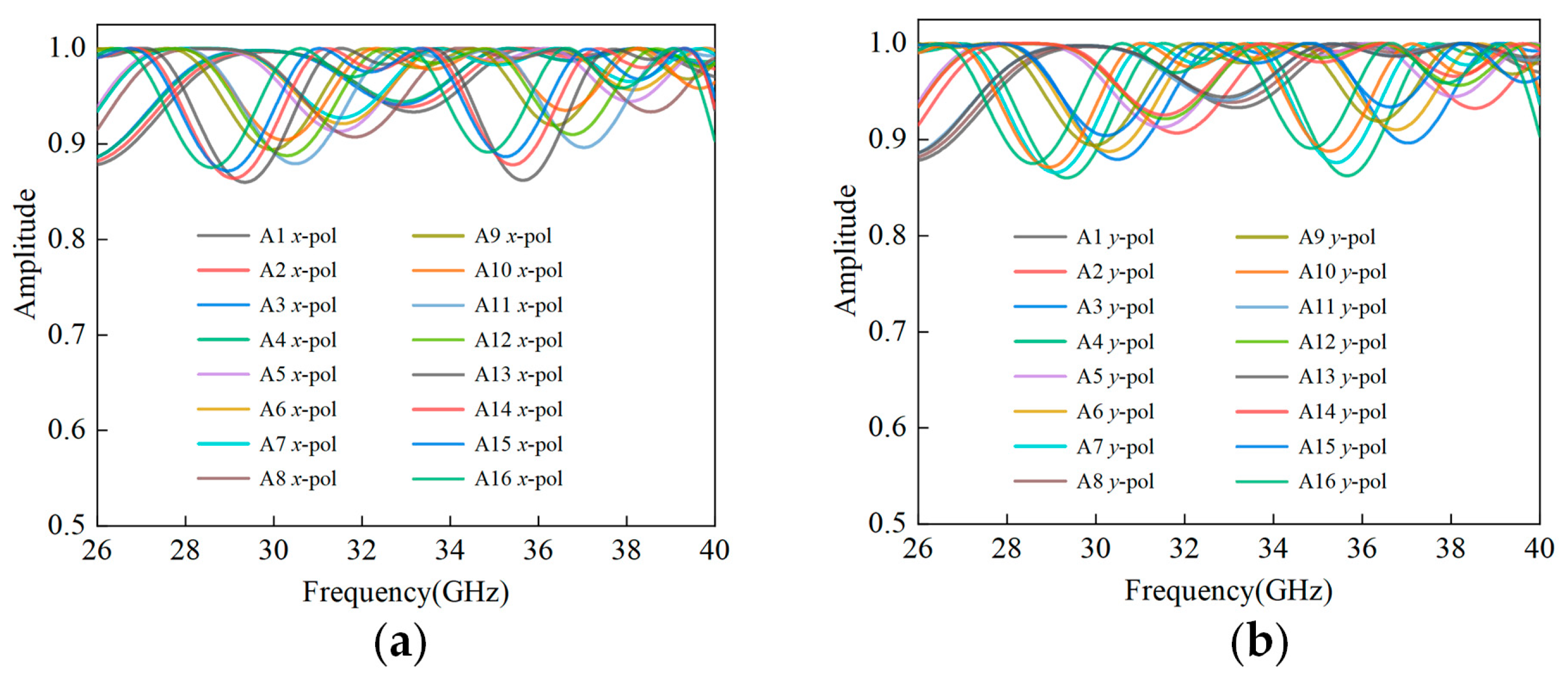
In Figure 3, the variation curves of the amplitude of each unit with frequency are presented. It can be observed that the transmission amplitudes of all units under both polarization conditions are higher than 0.85, demonstrating excellent transmission performance with low loss.
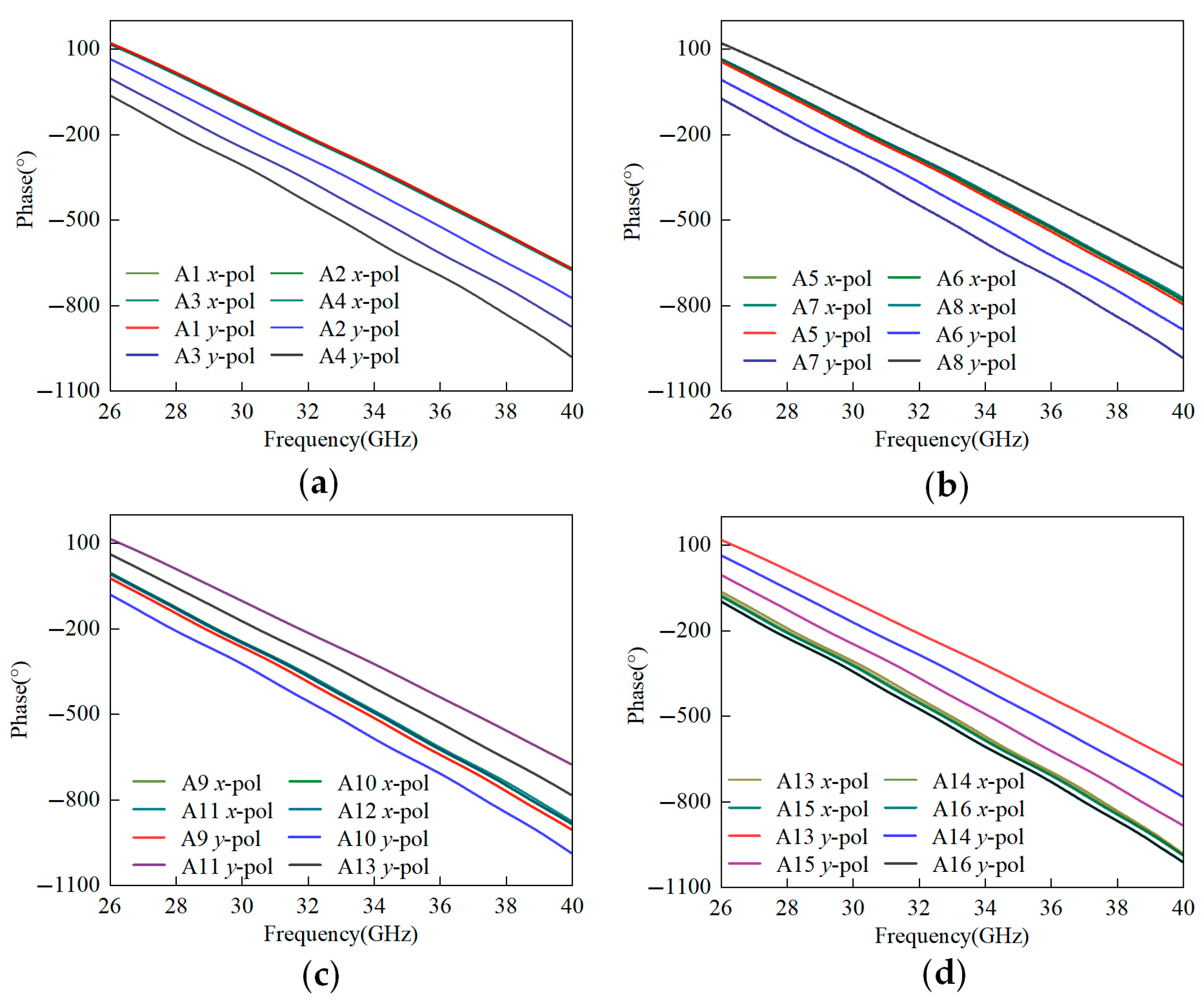
Figure 4 shows the phase variation curves of each unit with frequency. (a–d) are the dual-polarization phases of units A1 to A16, respectively. Each graph has eight curves, representing the phase curves of the four units when the theoretical phase of the x-polarization is 0°, 90°, 180°, and 270°, respectively. The results show that the phase shift curves of each unit are relatively smooth and parallel, indicating that the phase differences between units at different frequencies are stable.

2.2. Feed Design

Employing a horn antenna feed with uniform illumination across the transmitarray aperture ensures high gain and low sidelobes. It needs a stable phase center to generate near-linear phase distribution in the aperture plane. This enables a precise phase compensation design aligned with the feed’s phase characteristics. To simplify the design, a standardized 10 dBi gain horn antenna was adopted as the feeder. The parameters of the horn antenna are listed in Table 3.
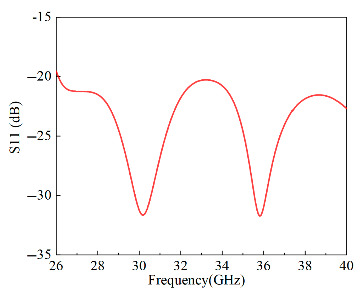
Figure 5 shows the reflection coefficient of the Ka-band horn antenna. The value is below –20 dB across the entire 26–40 GHz band, indicating excellent impedance-matching and minimal reflection loss.
Figure 6 exhibits the gain characteristics of the horn antenna. Quasi-linear gain progression was generated from 10.7 dBi at 26.5 GHz to 14.2 dBi at 40 GHz. The half-power beamwidth (HPBW) demonstrates angular compression from 56.2° at 26.5 GHz to 34.6° at 40 GHz, exhibiting a near-constant angular compression rate of 1.6°/GHz.
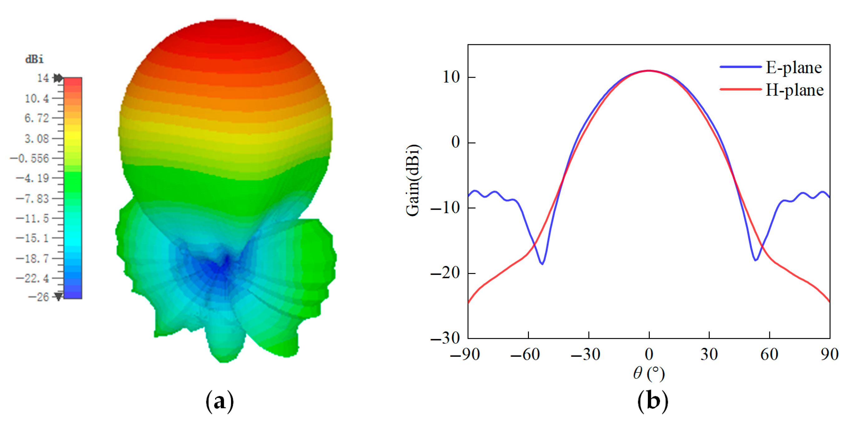
Figure 7 shows the 3D and 2D radiation patterns of the horn antenna. The peak gain is 12 dBi. The HPBWs in the two principal planes are almost the same. In addition, the sidelobe level is below −15 dB.

2.3. Array Design

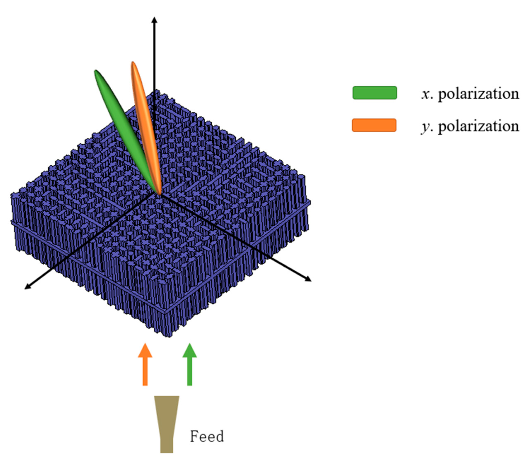
A 20 × 20 transmitarray with a 4.5 mm unit period was proposed, as shown in Figure 8. The aperture size of the array was 90 × 90 mm. The feed horn antenna was located at the center of the array. A focal-to-diameter (F/D) ratio of 0.8 was adopted to maximize the aperture efficiency. In order to verify the independent beam control of polarizations, the x-polarized beam was deflected to ( θ , φ ) = ( 20 , 0 ) , while the y-polarized beam was deflected to ( θ , φ ) = ( 20 , 30 ) . The required phase compensation from the feed horn to the transmitarray was calculated based on the classic theoretical equations. The phase distribution was quantized with 2-bit resolution. Finally, the phase was mapped into the physical parameters listed in Table 2.
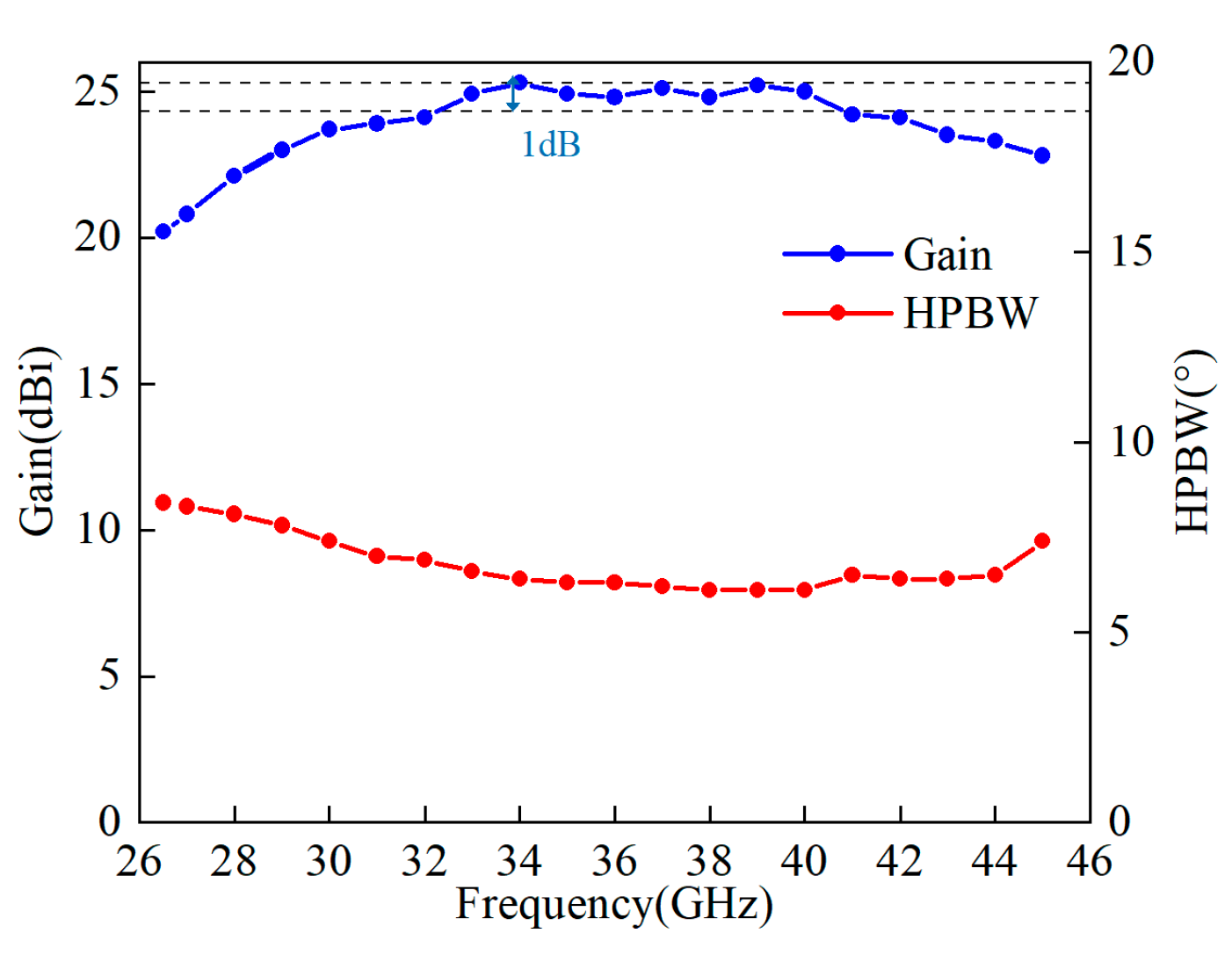
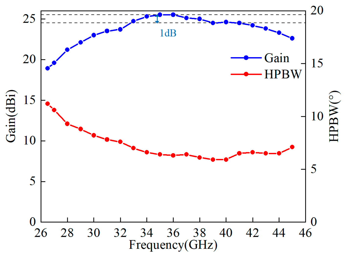
Figure 9 and Figure 10 reveal the radiation performances of the transmitarray under x-polarized and y-polarized wave illumination, respectively. In x-polarization, a peak gain of 25.3 dBi was obtained at 34 GHz. The 1 dB gain bandwidth achieves 10 GHz (32–42 GHz), yielding a 27% fractional bandwidth. In y-polarization, a peak gain of 25.5 dBi was obtained at 35 GHz. The 1 dB gain bandwidth achieves 8 GHz (33–41 GHz), maintaining a 22% fractional bandwidth.

2.4. Results and Discussion

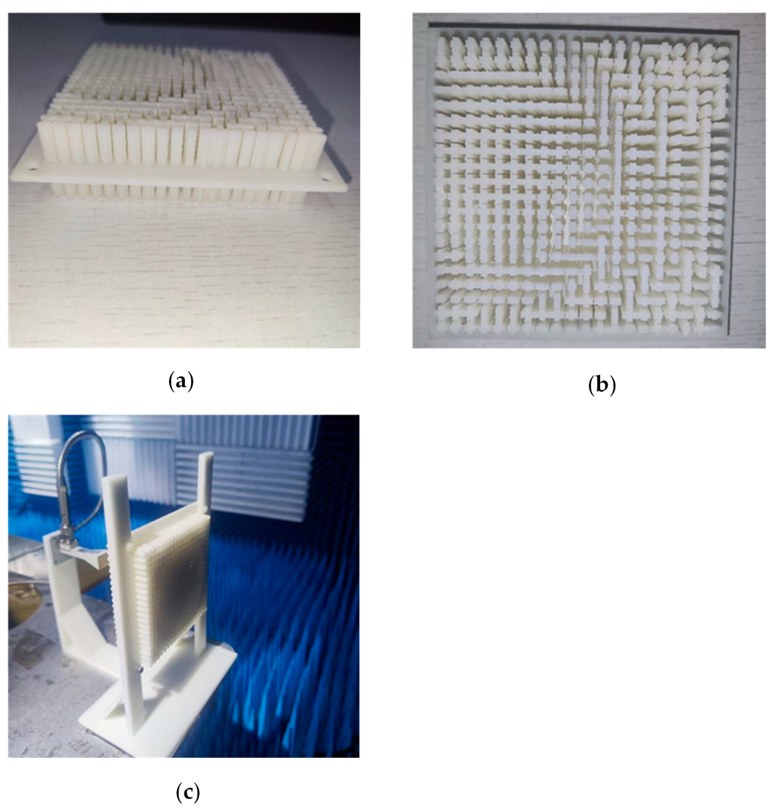
The prototype of the proposed transmitarray antenna was fabricated by using 3D-printed technology. The dielectric material was photosensitive resin with a dielectric constant of 3.2. Figure 11 shows a photograph of the fabricated transmitarray. It should be mentioned that the fabrication cost was very cheap (about USD 20).
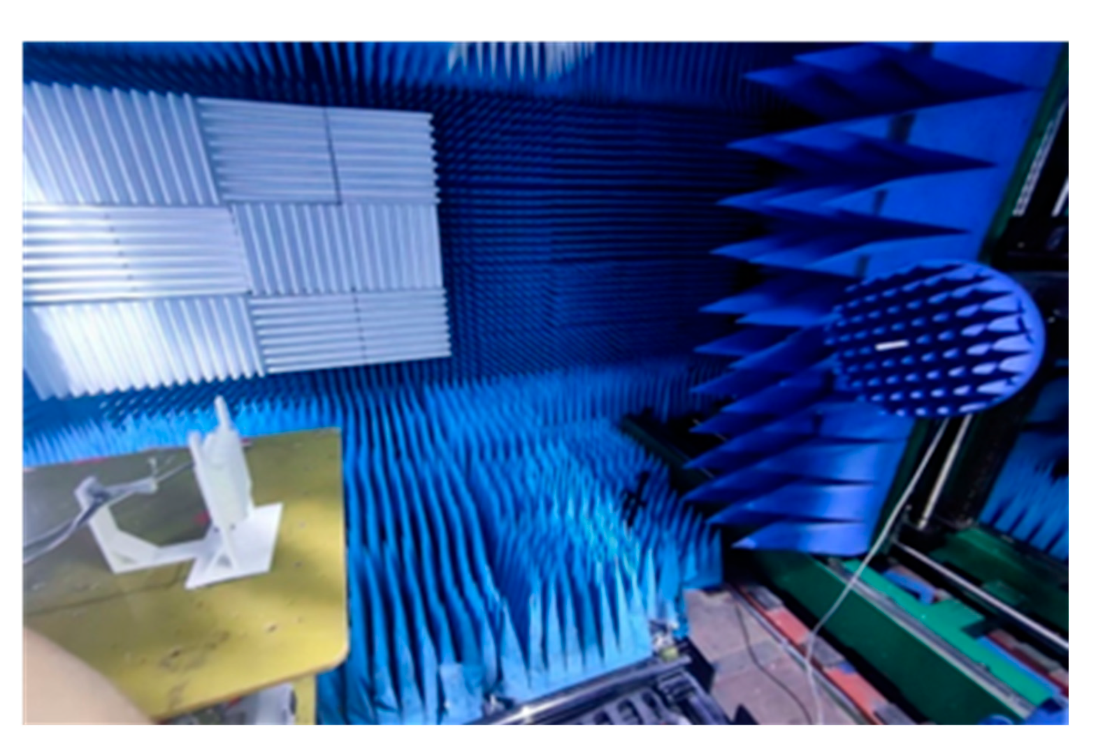
Figure 12 shows the test environment in a microwave anechoic chamber. Far-field measurement was adopted to measure the gain and radiation patterns. The gain was obtained through comparison with a standard gain horn antenna.
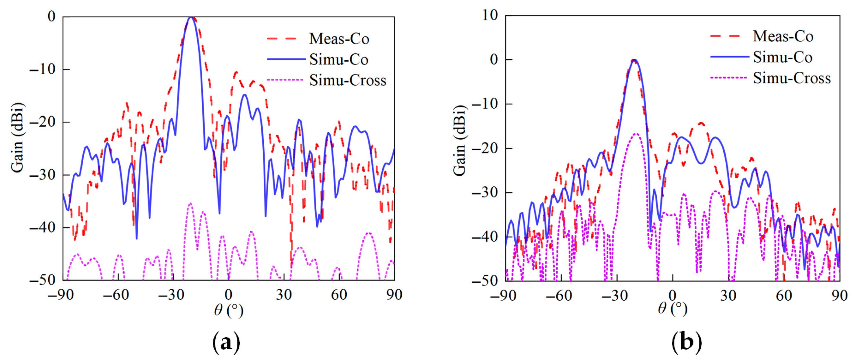
The simulated and measured radiation patterns of the transmitarray antenna are shown in Figure 13. The beamwidth of the measured result is slightly wider than that of the simulation result, and the deflection angle of the beam is consistent with that of the simulation result. The cross-polarization level was below −35 dB for the x-polarization, but the value deteriorated to −18 dB for the y-polarization.
Figure 14 depicts the simulated and measured gains as a function of the frequency under the two polarizations. Compared to the simulated results, the measured maximum gain in x-polarization is 25 dBi at 34 GHz, which is 0.3 dB lower than the simulated value of 25.3 dBi. The measured maximum gain in y-polarization is 24.8 dBi at 35 GHz, which is 0.7 dB lower than the simulated value of 25.5 dBi. Good agreement was achieved between the simulated and measured results.
The performances of the proposed transmitarray with the referenced state-of-the-art designs were compared, as listed in Table 4. It is shown that the proposed design has advantages in terms of aperture efficiency and gain bandwidth. Moreover, the all-dielectric property is the most attractive among these designs.

3. All-Dielectric Transmitarray Based on Dielectric Rod Antenna Array

In this section, the conventional horn feeder was replaced by dielectric rod antenna to reduce the cost. Multiple rod antennas were uniformly arranged to construct the feed array, which was used to generate multiple beams for discrete beam-scanning.

3.1. Dielectric Rod Design

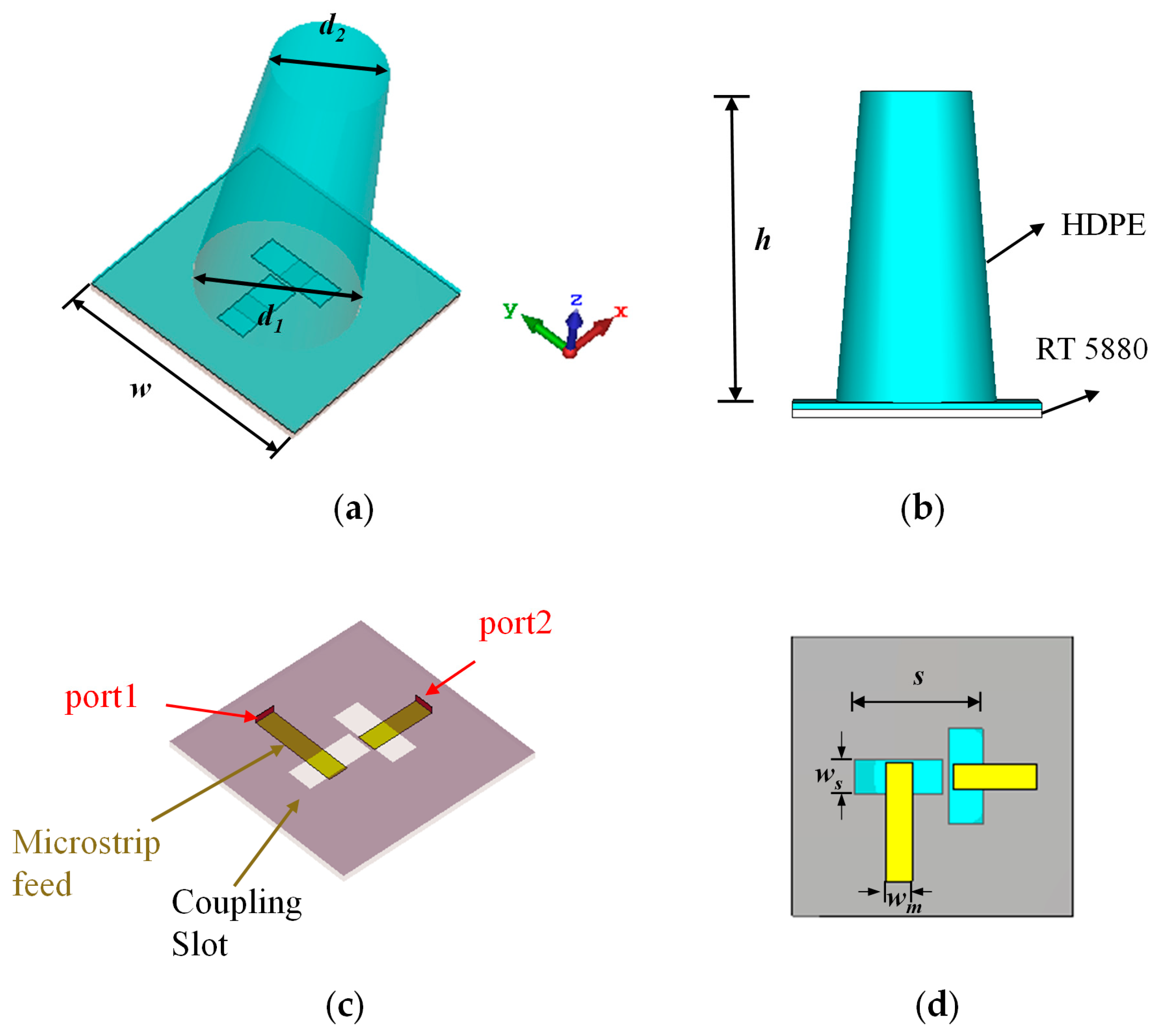
A novel dual-polarized dielectric rod feed antenna is presented. Figure 15 shows the geometry of the proposed structure. It features a monolithic four-layer architecture: (i) stacked dielectric substrates, (ii) truncated square pyramid dielectric rod, (iii) aperture-coupled ground plane, and (iv) orthogonally arranged 50 Ω microstrip feedlines. Instead of using bulky waveguide excitation, the proposed planar coupling feeding method greatly improves the planar integration of the structure, simplifies the design complexity, and reduces the cost. The dimensions of the parameters are shown in Table 5. The relative permittivity of the dielectric rod antenna was 2.3. The substrate board of the feeding network was made of Rogers RT 5880, with a relative permittivity of 2.2.
Figure 16 shows the reflection coefficient of the dual-polarized dielectric rod antenna. The two reflection coefficient curves are very close. The simulated −15 dB bandwidth of Port 1 ranges from 26.4 GHz to 28.5 GHz, while the bandwidth of Port 2 covers the 26.5–28.9 GHz band. The overlapping bandwidth of the two ports is 2 GHz.
Figure 17 shows the radiation patterns of the dual-polarized dielectric rod antenna. Figure 17a represents the x-polarization and Figure 17b represents the y-polarization. In x-polarization, the peak gain is 8.1 dBi, and the HPBW is 53.1°. In y-polarization, the peak gain is 8.3 dBi, and the HPBW is 64°. Regarding the cross-polarization performance of the antenna, all four curves are less than −30 dB. Due to a slight beam shift in the x-polarization case, the cross-polarization level slightly deteriorated.
The pros and cons of the conventional horn antenna and the dielectric rod array are discussed. While the horn antenna provides greater bandwidth and lower loss, its drawbacks include bulkiness and heavy weight. Conversely, the proposed dielectric rod array, despite its narrower bandwidth, benefits from simple, low-cost fabrication and direct integrability with circuits.

3.2. Transmitarray Design

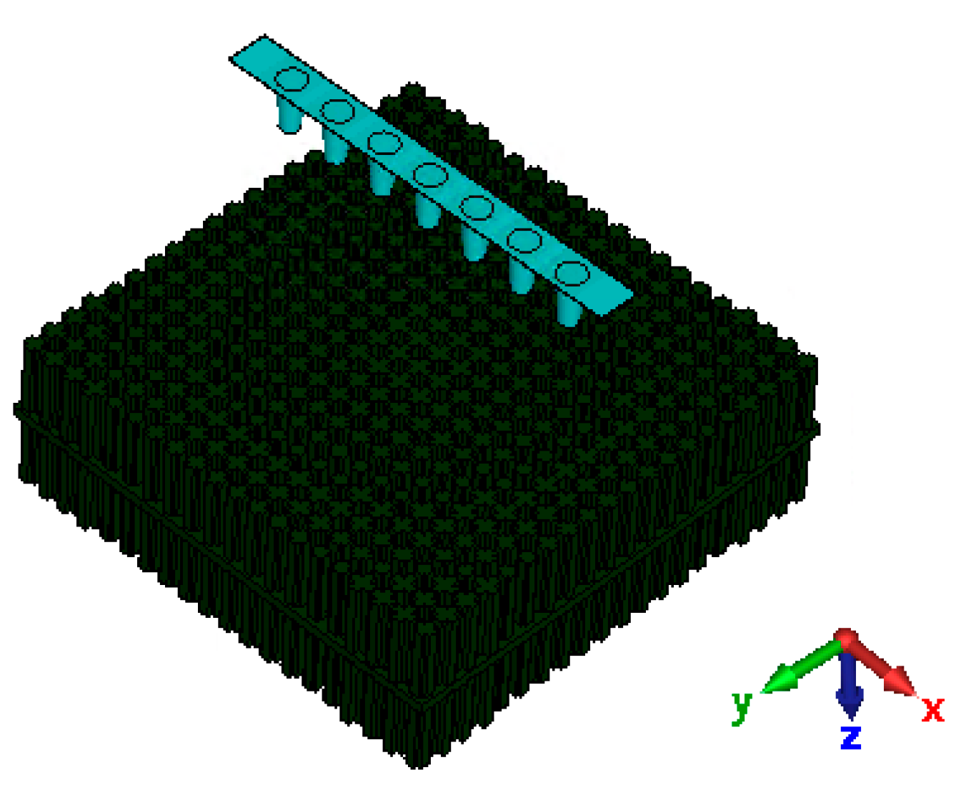
Following the same design theory, the transmittarray model was built based on the proposed dielectric rod antenna. Figure 18 shows a prototype of the transmitarray, fed by multiple feeders. The unit periodicity is still 4.5 mm. The 20 × 20 transmitarray occupies an aperture of 90 × 90 mm. An F/D ratio of 0.6 is adopted in this configuration. The vertical distance from the feed to the transmitarray is 54 mm. Multiple dielectric rod antennas are uniformly arranged to generate multiple beams.
Owing to the complexity involved, the dielectric rod antenna array and the transmitarray were not fabricated. The fabrication process involves manufacturing the dielectric rod array and the transmitarray using 3D-printing, while the feed network is fabricated using a standard PCB process. These components would then be assembled manually. The measurement process is also complex due to the presence of multiple feeding ports. Nonetheless, these are primarily engineering challenges that could be addressed through precise fabrication and rigorous measurement. They do not diminish the novelty of the proposed design and were omitted from this study for the sake of brevity.
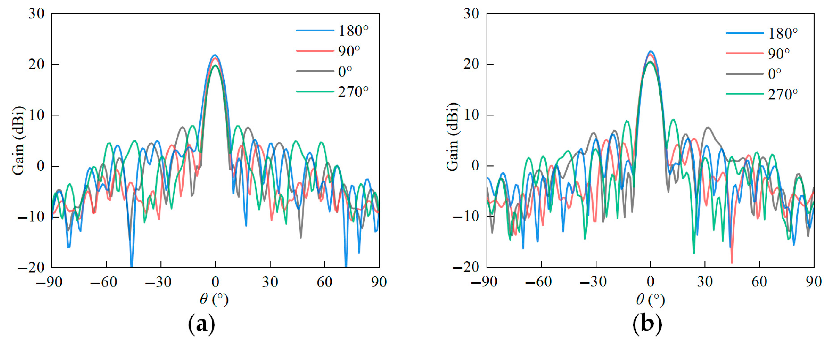
The reference phase of the transmitarray has a significant influence on the peak gain. Considering that the phase resolution is only 2-bit, the phase distribution of the transmitarray is different if the reference phase changes. Figure 19 presents four typical phase distributions with reference phases of 0°, 90°, 180°, and 270°. Figure 20 shows the corresponding radiation patterns of the transmitarray. All four cases can generate pencil beams. However, the peak gain varies significantly. Compared with the results in the 270° case, the peak gain is 2 dB higher and the sidelobe level is 8 dB lower in the 180° case. By sweeping the reference phase, the performances of the transmitarray can be greatly optimized.
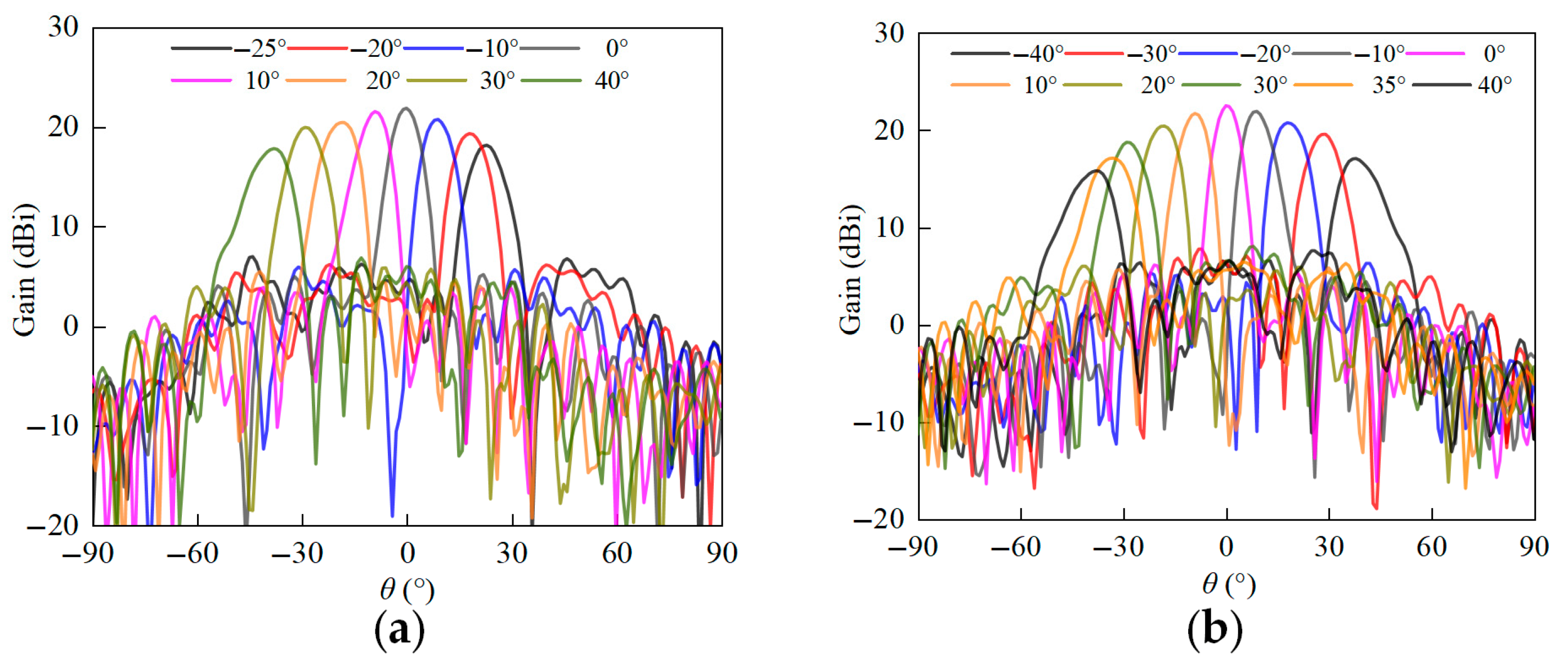
In order to achieve beam-scanning, the dielectric rod feed array is excited separately. Figure 21 shows the simulated radiation patterns of the transmitarray. It is shown that the x-polarized beam can be scanned from −25° to +35° and the y-polarized beam can be scanned from −35° to +25°. The peak gains of the two polarizations are 21.8 dBi and 22.5 dBi, respectively. The difference is mainly caused by the asymmetry of the feed antenna.
There are trade-offs in the proposed design. For example, while the unit cells lack tunability due to the all-dielectric structure, the dielectric rod feed array is reconfigurable to scan the beam. The unit cells feature a 2-bit phase resolution to reduce design complexity, at the cost of about 0.8 dB quantization loss. Although the dielectric rod feed array has a narrower bandwidth than a conventional feed horn, it is sufficient for most millimeter-wave applications.

4. Conclusions

This paper focuses on the design of Ka-band, dual-polarized, all-dielectric transmitarray antennas. A cross-shaped dielectric unit cell is proposed to achieve 360° phase modulation. A novel phase optimization algorithm is presented to achieve 2-bit phase resolution and used as an independent phase control for the x- and y- polarized waves. The prototype is fabricated by using 3D-printed technology. The measured x-/y-polarized peak gains are 25.3 dBi/25.5 dBi and the 1 dB bandwidths achieve 27% and 22%, respectively. Moreover, the conventional horn feeder is replaced by a dielectric rod antenna array feeder. The planar feed mechanism greatly reduces the design complexity. By exciting the dielectric rod antennas separately, the beam of the transmitarray can be scanned in the angle range of 60°. These improvements will provide great potential for the application of all-dielectric transmitarray antennas in 6G communications, satellite communications, and other related fields. In the future, the all-dielectric unit cells will be modified to integrate reconfigurable components for dynamic phase adjustment.

Author Contributions

Conceptualization, C.D.; methodology, B.L.; software, H.S; validation, B.L.; formal analysis, X.J.; investigation, J.Hu; resources, C.D.; data curation, H.S.; writing—original draft preparation, B.L.; writing—review and editing, H.S, X.J. and J.H.; visualization, X.J.; supervision, C.D.; project administration, C.D.; funding acquisition, C.D. All authors have read and agreed to the published version of the manuscript.

Funding

This work was supported in part by the Beijing Natural Science Foundation-Xiaomi Innovation Joint Fund Project under Contract L233020.

Data Availability Statement

All data are available from the author.

Conflicts of Interest

The authors declare no conflict of interest.

References

  1. Chen, S.; Kang, S. A tutorial on 5G and the progress in China. Front. Inf. Technol. Electron. Eng. 2018, 19, 309–321. [Google Scholar] [CrossRef]
  2. Askarian, A.; Wu, K. Aperture-shared radiation surface: A promising technique for multifunctional antenna array development. Electromagn. Sci. 2023, 1, 1–20. [Google Scholar] [CrossRef]
  3. Li, J.; Niu, Y.; Wu, H.; Ai, B.; Chen, S.; Feng, Z.; Zhong, Z.; Wang, N. Mobility support for millimeter wave communications: Opportunities and challenges. IEEE Commun. Surv. Tutor. 2022, 24, 1816–1842. [Google Scholar] [CrossRef]
  4. Deng, C.; Liu, D.; Yektakhah, B.; Sarabandi, K. Series-fed beam-steerable millimeter-wave antenna design with wide spatial coverage for 5G mobile terminals. IEEE Trans. Antennas Propag. 2020, 68, 3366–3376. [Google Scholar] [CrossRef]
  5. Shu, J.; Zhang, Y. Tailoring meta-liquid crystal for larger tunability. Electromagn. Sci. 2023, 1, 1–10. [Google Scholar] [CrossRef]
  6. Belshaw, J.C. Propagation effects at Ka-band: Review of the Olympus experience. In Proceedings of the IEE Colloquium on Future of Ka Band for Satellite Communications, London, UK, 15 November 1993; IET: London, UK, 1993; pp. 3/1–3/4. [Google Scholar]
  7. Xu, Z.; Deng, C. High-isolated MIMO antenna design based on pattern diversity for 5G mobile terminals. IEEE Antennas Wirel. Propag. Lett. 2020, 19, 467–471. [Google Scholar] [CrossRef]
  8. Fang, X.; Zheng, X.; Li, M.; Li, Z.; Ding, D. Wireless secure communication based on code domain space-time modulated metasurface. Electromagn. Sci. 2024, 2, 1–11. [Google Scholar] [CrossRef]
  9. Luo, Y.; Ji, R.; Zhang, Y. Performance analysis of planar Luneburg lens and full dielectric lens. In Proceedings of the 2022 IEEE 10th Asia-Pacific Conference on Antennas and Propagation (APCAP), Xiamen, China, 4–7 November 2022; IEEE: New York, NY, USA, 2022; pp. 1–2. [Google Scholar]
  10. Cao, X.; Deng, C.; Yin, Y.; Hao, Y.; Sarabandi, K. 1-bit reconfigurable transmit-and reflect-array antenna using patch-ground-patch structure. IEEE Antennas Wirel. Propag. Lett. 2023, 23, 434–438. [Google Scholar] [CrossRef]
  11. Deng, C.; Liu, D.; Lv, X. Tightly arranged four-element MIMO antennas for 5G mobile terminals. IEEE Trans. Antennas Propag. 2019, 67, 6353–6361. [Google Scholar] [CrossRef]
  12. Milne, R. Dipole array lens antenna. IEEE Trans. Antennas Propag. 1982, 30, 704–712. [Google Scholar] [CrossRef]
  13. Luk, K.M.; Xiang, B. Transmitarray and reflectarray antennas based on a magnetoelectric dipole antenna. Electromagn. Sci. 2023, 1, 1–14. [Google Scholar] [CrossRef]
  14. An, W.; Hong, L.; Li, S. A double-layer transmitarray element based on complementary FSS structure. In Proceedings of the 2018 Cross Strait Quad-Regional Radio Science and Wireless Technology Conference (CSQRWC), Xuzhou, China, 21–24 July 2018; pp. 1–2. [Google Scholar]
  15. Hsu, C.Y.; Hwang, L.T.; Lee, P.S.; Wang, S.M.; Chang, F.S. Design of a high gain and dual polarized transmitarray using FSS of smaller unit cells. In Proceedings of the 2016 International Symposium on Antennas and Propagation (ISAP), Okinawa, Japan, 24–28 October 2016; pp. 776–777. [Google Scholar]
  16. Mei, P.; Pedersen, G.F.; Zhang, S. A broadband and FSS-based transmitarray antenna for 5G millimeter-wave applications. IEEE Antennas Wirel. Propag. Lett. 2021, 20, 103–107. [Google Scholar] [CrossRef]
  17. Abdelrahman, A.H.; Elsherbeni, A.Z.; Yang, F. Transmission phase limit of multilayer frequency-selective surfaces for transmitarray designs. IEEE Trans. Antennas Propag. 2014, 62, 690–697. [Google Scholar] [CrossRef]
  18. Ryan, C.G.M.; Chaharmir, M.R.; Shaker, J.; Bray, J.R.; Antar, Y.M.M.; Ittipiboon, A. A wideband transmitarray using dual-resonant double square rings. IEEE Trans. Antennas Propag. 2010, 58, 1486–1493. [Google Scholar] [CrossRef]
  19. Menzel, W.; Pilz, D.; Al-Tikriti, M. Millimeter-wave folded reflector antennas with high gain, low loss, and low profile. IEEE Antennas Propag. Mag. 2002, 44, 24–29. [Google Scholar] [CrossRef]
  20. Feng, Y.; Hu, Q.; Qu, K.; Yang, W.; Zheng, Y.; Chen, K. Reconfigurable intelligent surfaces: Design, implementation, and practical demonstration. Electromagn. Sci. 2023, 1, 1–21. [Google Scholar] [CrossRef]
  21. Keller, M.; Shaker, J.; Petosa, A.; Ittipiboon, A.; Cuhaci, M.; Antar, Y. A Ka-band dielectric resonator antenna reflectarray. In Proceedings of the 2000 30th European Microwave Conference, Paris, France, 2–5 October 2000; pp. 1–4. [Google Scholar]
  22. Liu, Y.; Wang, H.; Dong, X. Design of a double-layer dielectric-only transmitarray antenna for THz application. In Proceedings of the 2018 IEEE International Symposium on Antennas and Propagation & USNC/URSI National Radio Science Meeting, Boston, MA, USA, 8–13 July 2018; IEEE: New York, NY, USA, 2018; pp. 1191–1192. [Google Scholar]
  23. Wei, F.; Hao, J.-W.; Xu, L.; Shi, X. A circularly polarized 3-D printed dielectric transmitarray antenna at millimeter-wave band. IEEE Antennas Wirel. Propag. Lett. 2021, 20, 1264–1268. [Google Scholar] [CrossRef]
  24. Massaccesi, A.; Pirinoli, P. Space-fed antenna based on dielectric-only transmitarray. In Proceedings of the 2022 16th European Conference on Antennas and Propagation (EuCAP), Madrid, Spain, 27 March–1 April 2022; IEEE: New York, NY, USA, 2022; pp. 1–4. [Google Scholar]
  25. Liu, X.; Peng, L.; Liu, Y.-F.; Yu, W.-S.; Zhao, Q.-X.; Jiang, X.; Li, S.-M.; Ruan, C. Ultrabroadband all-dielectric transmitarray designing based on genetic algorithm optimization and 3-D print technology. IEEE Trans. Antennas Propag. 2021, 69, 2003–2012. [Google Scholar] [CrossRef]
  26. Zhao, W.G.; Wang, J.; Tian, L.; Wu, F. A planar wideband circularly polarized dielectric transmitarray with compound phase tuning. In Proceedings of the 2023 IEEE 11th Asia-Pacific Conference on Antennas and Propagation (APCAP), Guangzhou, China, 22–24 November 2023; IEEE: New York, NY, USA, 2023; pp. 1–2. [Google Scholar]
  27. Serup, D.E.; Zhang, S.; Pedersen, G.F. Detailed design procedure for low-cost high-efficiency 3D printed transmitarray antennas for mm-wave applications. In Proceedings of the 2024 18th European Conference on Antennas and Propagation (EuCAP), Glasgow, UK, 17–22 March 2024; IEEE: New York, NY, USA, 2024; pp. 1–5. [Google Scholar]
  28. Liu, C.; Yang, F.; Xu, S.; Li, M. Reconfigurable metasurface: A systematic categorization and recent advances. Electromagn. Sci. 2023, 1, 1–23. [Google Scholar] [CrossRef]
  29. Wu, K.; Qin, P.; Chen, S.L. A high-efficiency 3D-printed E-band dielectric transmitarray for integrated space and terrestrial networks. In Proceedings of the 2022 International Symposium on Antennas and Propagation (ISAP), Sydney, Australia, 31 October–3 November 2022; pp. 319–320. [Google Scholar]
  30. Dicandia, F.A.; Genovesi, S. Low profile dielectric transmitarray based on additive manufacturing technology. In Proceedings of the 2023 IEEE Conference on Antenna Measurements and Applications (CAMA), Genoa, Italy, 15–17 November 2023; IEEE: New York, NY, USA, 2023; pp. 804–807. [Google Scholar]
  31. Massaccesi, A.; Pirinoli, P.; Vardaxoglou, J.C. A multilayer unit-cell for perforated dielectric transmitarray antennas. In Proceedings of the 2018 IEEE International Symposium on Antennas and Propagation & USNC/URSI National Radio Science Meeting, Boston, MA, USA, 8–13 July 2018; IEEE: New York, NY, USA, 2018; pp. 263–264. [Google Scholar]
  32. Vaquero, Á.F.; Teixeira, J.; Matos, S.A.; Arrebola, M.; Costa, J.R.; Felício, J.M.; Fernandes, C.A.; Fonseca, N.J.G. Design of low-profile transmitarray antennas with wide mechanical beam steering at millimeter waves. IEEE Trans. Antennas Propag. 2023, 71, 3713–3718. [Google Scholar] [CrossRef]
  33. Kupriianov, A.S.; Tuz, V.R.; Shcherbinin, V.I.; Trubin, A.; Fesenko, V.I. All-dielectric Vogel metasurface antennas with bidirectional radiation pattern. J. Opt. 2020, 22, 035104. [Google Scholar] [CrossRef]
  34. Cao, X.; Deng, C.; Hao, Y.; Yin, Y. Wideband 3-D printed all-metal reflectarray with notches for low-cost millimeter-wave applications. IEEE Open J. Antennas Propag. 2023, 4, 118–125. [Google Scholar] [CrossRef]
  35. Hao, Y.; Deng, C.; Cao, X.; Yin, Y.; Sarabandi, K. high aperture efficiency 1-bit reconfigurable reflectarray antenna with extremely low power consumption. IEEE Trans. Antennas Propag. 2023, 72, 1015–1020. [Google Scholar] [CrossRef]
  36. Ali, Q.; Shahzad, W.; Ahmad, I.; Safiq, S.; Bin, X.; Abbas, S.M.; Sun, H. Recent developments and challenges on beam steering characteristics of reconfigurable transmitarray antennas. Electronics 2022, 11, 587. [Google Scholar] [CrossRef]
  37. Vaquero, Á.F.; Pino, M.R.; Arrebola, M.; Matos, S.A.; Costa, J.R.; Fernandes, C.A. Evaluation of a dielectric-only transmitarray for generating multi-focusing near-field spots using a cluster of feeds in the Ka-band. Sensors 2021, 21, 422. [Google Scholar] [CrossRef]
  38. Alkaraki, S.; Ullah Khan, Z.; Jilani, S.F.; Andre Sarker, A.; Kelly, J.R.; Alomainy, A. Low–cost 3D–printed standard gain horn antennas for millimetre–wave applications. J. Manuf. Mater. Process. 2025, 9, 222. [Google Scholar] [CrossRef]
  39. Gülseren, A.H.; Alparslan, A.; Türker Tokan, N. Dual-band frequency selective surface-backed reflectarray for high-speed Ka-band satellites. Appl. Sci. 2024, 14, 2928. [Google Scholar] [CrossRef]
  40. Tayyab, U.; Kumar, A.; Petry, H.-P.; Asghar, M.E.; Hein, M.A. Dual-band nested circularly polarized antenna array for 5G automotive satellite communications. Appl. Sci. 2023, 13, 11915. [Google Scholar] [CrossRef]
  41. Zhang, Y.; Luo, Y.; Ji, R. Millimeter-wave high-gain dual-polarized flat Luneburg lens antenna with reflection cancellation. Appl. Sci. 2023, 13, 6468. [Google Scholar] [CrossRef]
  42. Wu, S.; Li, J.; Cao, Y.; Yan, S.; Xu, K.; Luyen, H. Three-dimensional printed, dual-band, dual-circularly polarized antenna array using gap waveguide technology. Appl. Sci. 2022, 12, 10704. [Google Scholar] [CrossRef]
  43. Mohammed, A.H.; Alnahwi, F.M.; Al-Yasir, Y.I.A. A circularly polarized microstrip antenna with dual circular polarization using a 90° hybrid coupler and proximity-coupled feeding for LTE 43 5G applications. Appl. Sci. 2024, 14, 11877. [Google Scholar] [CrossRef]
  44. Yin, Y.; Deng, C.; Cao, X.; Hao, Y.; Hou, Y.; Xu, H.; Sarabandi, K. Design of a 2-bit dual-polarized reconfigurable reflectarray with high aperture efficiency. IEEE Trans. Antennas Propag. 2023, 72, 542–552. [Google Scholar] [CrossRef]
  45. Wang, Y.; Xu, S.; Yang, F.; Werner, D.H. 1 bit dual-linear polarized reconfigurable transmitarray antenna using asymmetric dipole elements with parasitic bypass dipoles. IEEE Trans. Antennas Propag. 2020, 69, 1188–1192. [Google Scholar] [CrossRef]
  46. Wu, F.; Wang, J.; Xiang, L.; Hong, W.; Luk, K.-M. A wideband dual-polarized magneto-electric dipole transmitarray with independent control of polarizations. IEEE Trans. Antennas Propag. 2022, 70, 8632–8636. [Google Scholar] [CrossRef]
  47. Pham, K.; Nguyen, N.T.; Clemente, A.; Di Palma, L.; Le Coq, L.; Dussopt, L.; Sauleau, R. Design of wideband dual linearly polarized transmitarray antennas. IEEE Trans. Antennas Propag. 2016, 64, 2022–2026. [Google Scholar] [CrossRef]
  48. Huang, C.; Pan, W.; Ma, X.; Zhao, B.; Cui, J.; Luo, X. Using reconfigurable transmitarray to achieve beam-steering and polarization manipulation applications. IEEE Trans. Antennas Propag. 2015, 63, 4801–4810. [Google Scholar] [CrossRef]
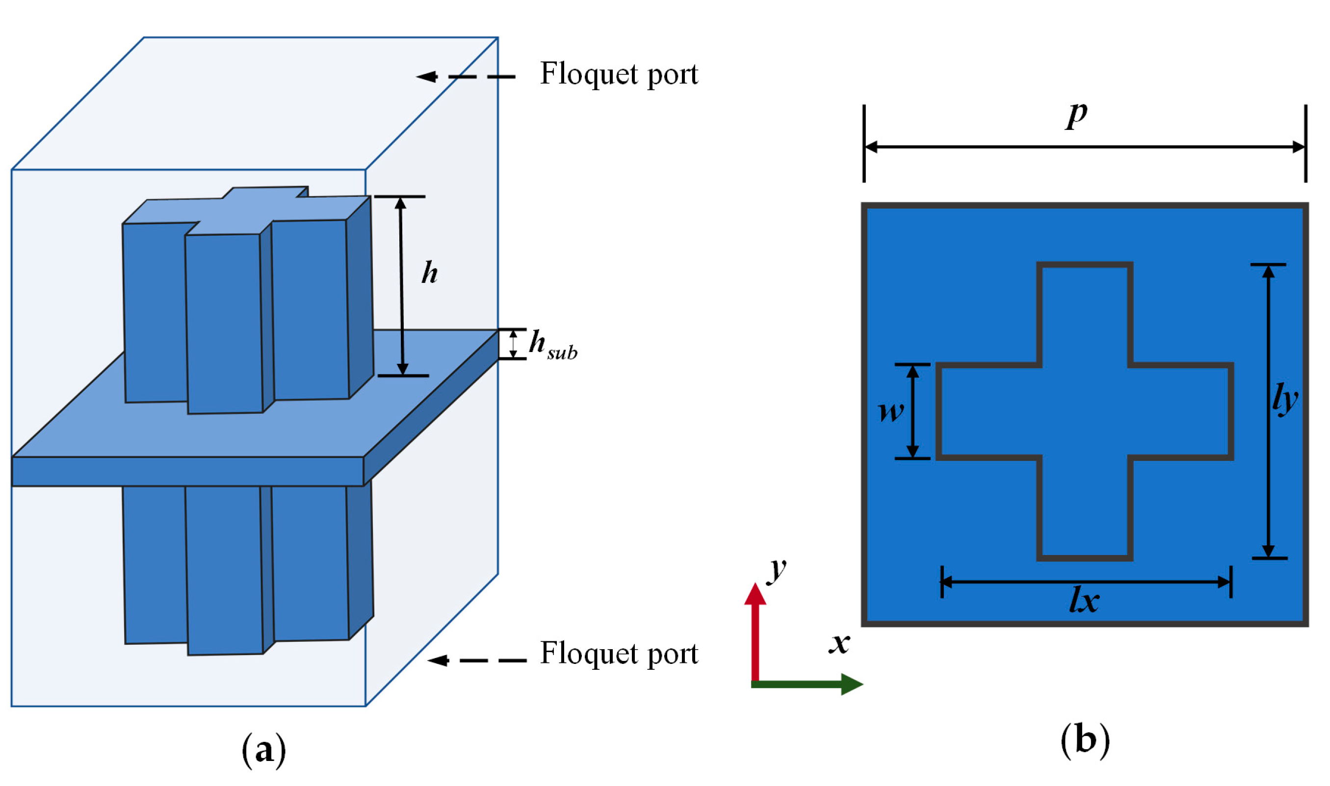
Figure 1. Unit structure of the transmitarray. (a) Three-dimensional view; (b) top view.
Applsci 15 09560 g001
Figure 2. The influence of ly on the phase of the two polarizations.
Applsci 15 09560 g002
Figure 3. The transmission amplitudes, varying with frequency. (a) x-polarization; (b) y-polarization.
Applsci 15 09560 g003
Figure 4. Diagram of unit phase variation with frequency. (a) A1–A4; (b) A5–A8; (c) A9–A12; (d) A13–A16.
Applsci 15 09560 g004
Figure 5. Reflection coefficient of Ka-band horn antenna.
Applsci 15 09560 g005
Figure 6. The gain and beamwidth of the horn antenna with frequency. (a) Gain curve; (b) half-power beamwidth curve.
Applsci 15 09560 g006
Figure 7. Far-field diagram of the horn antenna at 33 GHz. (a) Three-dimensional radiation far-field diagram; (b) two-dimensional radiation pattern.
Applsci 15 09560 g007
Figure 8. All-dielectric transmitarray fed by a horn antenna.
Applsci 15 09560 g008
Figure 9. The variation in gain and HPBW at different frequencies with x-polarization.
Applsci 15 09560 g009
Figure 10. The variation in gain and HPBW at different frequencies with y-polarization.
Applsci 15 09560 g010
Figure 11. Photograph of the fabricated transmitarray. (a) Stereoscopic view; (b) top view; (c) assembled prototype.
Applsci 15 09560 g011
Figure 12. Test scenario in the microwave anechoic chamber.
Applsci 15 09560 g012
Figure 13. The simulated and measured radiation patterns with different beams. (a) x-polarization at (20°, 0°); (b) y-polarization at (20°, 30°).
Applsci 15 09560 g013
Figure 14. The simulated and measured gains with frequency. (a) x-polarization; (b) y-polarization.
Applsci 15 09560 g014
Figure 15. Geometry of the dielectric rod feed antenna. (a) 3D view; (b) side view; (c) feed network; (d) bottom view.
Applsci 15 09560 g015
Figure 16. Simulated reflection coefficients of the dielectric rod antenna.
Applsci 15 09560 g016
Figure 17. The radiation patterns of the dielectric rod antenna at 28 GHz. (a) x-polarization; (b) y-polarization.
Applsci 15 09560 g017
Figure 18. The prototype of the transmitarray fed by multiple dielectric rod antennas.
Applsci 15 09560 g018
Figure 19. The phase distribution of the transmitarray with different reference phases. (a) 0°; (b) 90°; (c) 180°; (d) 270°.
Applsci 15 09560 g019
Figure 20. The influence of reference phase on dual-polarized arrays. (a) x-polarization; (b) y-polarization.
Applsci 15 09560 g020
Figure 21. Dual-polarized beam-scanning of the transmitarray. (a) x-polarization; (b) y-polarization.
Applsci 15 09560 g021
Table 1. Parameters of the dual-polarized unit cell.
ParameterValue (mm)
p4.5
h12
w1.7
hsub2
Table 2. The physical size and the corresponding phase modulation.
Unitlx (mm)ly (mm)Theoretical x-Pol Phase (°)Theoretical y-Pol Phase (°)Actual x-Pol Phase (°)Actual y-Pol Phase (°)
A12.62.6270270264264
A23.43.2270180262190
A34.12.127090256103
A44.51.9270026022
A52.33.4180270190262
A63.23.2180180176176
A73.92.918090185108
A84.42.7180018821
A92.14.190270103256
A102.93.990180108186
A113.83.890909494
A124.33.590010826
A131.94.5027022261
A142.74.4018021188
A153.54.309026112
A164.34.3001515
Table 3. Parameters of the Ka-band horn antennas.
ParameterValue (mm)ParameterValue (mm)
Aperture Length7Horn Opening Length17
Aperture Width3.5Horn Opening Width12
Waveguide Length31Axial Length of Horn20
Table 4. Comparison of the proposed transmitarray with other works.
RefFrequency (GHz)Number of ElementsGain (dBi)Aperture Efficiency1 dB Gain Bandwidth
[45]11.510 × 1018.322.6%11.5%
[46]2716 × 162431%23%
[47]1020 × 2025.324%19%
[48]5.48 × 81728%9%
This work3420 × 2025.525.7%27%
Table 5. Dimensions of the dual-polarized dielectric rod antennas.
ParameterValue (mm)
w8
h10
d15.2
d23.6
s3.66
ws1
wm0.74
Disclaimer/Publisher’s Note: The statements, opinions and data contained in all publications are solely those of the individual author(s) and contributor(s) and not of MDPI and/or the editor(s). MDPI and/or the editor(s) disclaim responsibility for any injury to people or property resulting from any ideas, methods, instructions or products referred to in the content.