1. Introduction
The air conditioning fan is a crucial component in air conditioning systems. Its aerodynamic performance directly determines the user experience of the air conditioner and influences its energy consumption. Additionally, the fan noise significantly impacts in-vehicle comfort. Abundant research shows that when the air conditioning system operates under high load, the noise level inside the vehicle can exceed 60 dB. Prolonged exposure to this high noise state harms people’s health and reduces vehicle driving safety [
1]. Thus, optimizing the aerodynamic performance of the air conditioning fan and reducing its noise are essential. These improvements not only enhance the overall performance of the air conditioning system but also create a more comfortable and safe in-vehicle environment. In contrast to other fan types, the multi-wing centrifugal fan offers distinct advantages, chief among them being its compact structure and substantial air volume delivery capacity. Owing to these favorable attributes, it has found extensive application within the air-conditioning domain. Nevertheless, the multi-wing centrifugal fan is also characterized by a relatively short blade passage and a small blade wrap angle. These inherent structural features give rise to suboptimal working efficiency of the fan, thereby resulting in significant energy consumption within the air conditioning system [
2]. The generation of fan noise is closely related to the flow field. Aerodynamic noise is the primary type of fan noise, and some scholars have conducted research in this regard. Lighthill et al. [
3] propose the Lighthill equation, which serves as the fundamental equation of aeroacoustics. Frowcs et al. [
4], building on the previous research, put forward the FW-H equation, which solved the problem of sound generation by moving objects in fluids. Goldstein et al. [
5] supplement the FW-H equation, breaking through the original assumption in the FW-H equation that the propagation medium velocity of the noise source is zero. Sundstrom et al. [
6] extended the FW-H method to non-zero velocity flow situations such as rotational stall in centrifugal compressors and achieved quantification of the acoustic source distribution and propagation characteristics. The proposal of basic equations of aeroacoustics has provided a crucial foundation for subsequent theoretical studies on fan noise, enabling understanding of noise to develop from qualitative to quantitative.
Noise has a direct impact on the aerodynamic performance of fans. Thus, researching the noise within fans and the associated flow fields is of particular significance. Powell et al. [
7] elucidate the relationship between turbulence and acoustic energy, indicating that in unsteady fluid flows, aerodynamic sound is generated as a result of the movement of vortices and vorticity. In a slightly compressible fluid, vorticity can be regarded as inducing the entire flow field, and this property can be utilized to evaluate the sound radiation formula. The framework of this theory facilitates the estimation of flow-induced sound based on vorticity. Lowson et al. [
8] employ the Fourier series expansion method to derive the discrete noise model of the rotating impeller as well as the discrete noise model of the mutual interference between the blade and the guide vane. This model can also serve to guide the aerodynamic design of fans. Amiet et al. [
9] derive the expression of blade wake noise by taking the pressure pulsation on the trailing edge surface of the blade as the input, thereby further enriching the blade noise theory. Wang et al. [
10] drew inspiration from the swimming characteristics of carps in the C-shaped starting posture and carried out a bionic design of the blade. Through the application of the reverse engineering method, Bionic Equal Thickness Blades (BETBs) inspired by the C-shaped starting mid-arc of carp are designed and optimized. Based on the comparison between the numerical and experimental results of the fan’s aerodynamic performance, the Optimal Bionic Equal Thickness Blade (O-BETB) is obtained. When the O-BETBs are applied to the original fan, the flow rate increases by 6.8% and the noise decreases by
dB(A). Mao et al. [
11] compute the unsteady flow field inside the centrifugal fan and use the results to identify the location and type of the primary aerodynamic noise sources within the fan. Additionally, by means of time-domain and frequency-domain analysis methods, the distribution characteristics of the amplitude and frequency of the pressure pulsation can be obtained in the flow field. By comparing these results with the noise test findings, a technique is proposed that can effectively provide information for fan noise reduction design without directly solving the sound field. Furthermore, the selection of an appropriate turbulence calculation model is crucial for accurately determining the fan flow-field information when calculating fan noise. In this regard, some scholars have conducted relevant research. Liu et al. [
12] utilize the Large Eddy Simulation (LES) method [
13] to calculate the internal flow field of the centrifugal fan. The results indicated that the vortex sound theory can predict noise more accurately than the acoustic analogy method, and the results are closer to the experimental values. Dai et al. [
14] simulate the aerodynamic noise of a small, high-speed centrifugal fan for aerospace applications using a variety of turbulence models. The results demonstrate that the LES model, which can be applied to the noise reduction design of this type of fan, is in the best agreement with the experimental results. The volute tongue is an important part of a multi-wing centrifugal fan. Under the high-speed drainage of the impeller, the gas is discharged into the pipeline connected to the volute tongue through the volute collection, flow diversion, and pressure expansion. The volute tongue can effectively prevent the gas from circulating into the volute tongue, and the structural parameters of the fan have the greatest influence under the rated flow rate [
15]. Turbulence and eddy flow are important factors that affect the noise of the fan and directly affect the aerodynamic performance of the fan. The turbulence calculation model has a general understanding of the noise flow in the fan, but the structure of the fan directly affects the formation and change of turbulence and eddy flow, and the rationality of the fan structure is strictly required.
The blades on the impeller hit the surrounding gas medium, which will cause the surrounding gas to produce pressure pulsation and thus generate noise. The main reason for this is that the boundary layer on the blade surface is seriously separated during the rotation process, and then the eddy flow is generated. The shedding of eddy flow will cause large pressure pulsation, and the impeller blades periodically squeeze and beat surrounding air particles. Finally, it is reflected on the adjacent fan’s volute tongue, so the volute tongue becomes the main generating position of fan noise [
16]. Liu et al. [
17] use Particle Image Velocimetry (PIV) to study the velocity distribution characteristics of the centrifugal fan used for air conditioning along the height of the blade and find that the asymmetry of the volute structure has a greater influence on the airflow velocity, which is reflected by the larger velocity gradient near the volute tongue. On both sides of the volute with larger flowable space, the airflow velocity is evenly distributed. Zhang et al. [
18] are concerned about the uneven generation and distribution of fan tracer particles under large flow rates and propose a method of indoor pre-dissemination of tracers to capture the flow at the fan inlet with high resolution. Kawasaki et al. [
19] use PIV technology to measure the flow situation near the volute tongue, which is basically consistent with the simulation results. There is a large turbulence loss near the volute tongue, that is, the structure of the volute tongue is the key factor affecting the aerodynamic performance of the fan. Younsi et al. [
20] use numerical methods to study the changes of unsteady flow and noise in forward-bending centrifugal fans with different structural parameters, and by comparing with the test results the relationship between pressure pulsation on the volute wall and far-field noise is highlighted. Rong et al. [
21] use numerical methods to study the flow situation in the blade channels before and after blade surface grooving and find that the grooving treatment could effectively inhibit the boundary layer separation on the blade surface, and the separation loss in the blade channel is reduced, but the grooving treatment will slightly reduce the effect of the volute tongue on preventing air return. Morinushi et al. [
22] compare forward-bending centrifugal fans with different structural parameters and find that the impeller’s working efficiency is the highest when the radius of the volute tongue is
times. Liu et al. [
23] effectively reduce the overall noise of the fan by increasing the clearance between the impeller and the volute tongue and reduce the sound pressure level under the blade frequency by 15 dB. The results show that the volute tongue clearance is closely related to the noise of the centrifugal fan. Cheong et al. [
24] use the mixed CAA method to analyze the contribution degree of the volute tongue region to the noise of centrifugal fans, and the results show that the region between the blade outlet and the spiral casing generated more noise than the region between the blade outlet and the spiral casing outlet. Therefore, the gap between the impeller and the volute tongue could be focused on as the main location for noise reduction. In addition to the volute tongue, the volute profile will affect the flow characteristics of gas in the fan and then affect the aerodynamic performance and noise. Therefore, more scholars have begun to pay attention to the role of volute profile in improving the performance of fans. Zhou et al. [
25] highlight that due to the asymmetric structure characteristics of the volute, the airflow at the inlet of the volute is unevenly distributed, so the volute profile is redesigned according to the flow distribution at the inlet, effectively improving the performance of the centrifugal fan. Zhang et al. [
26] modify the volute profile of the forward-bending centrifugal fan, taking into account the influence of gas viscosity, and the test showed that the noise of the fan is reduced by 1.1 dB, especially in the low frequency band. This study provides a new idea for volute design closer to the real situation. Li et al. [
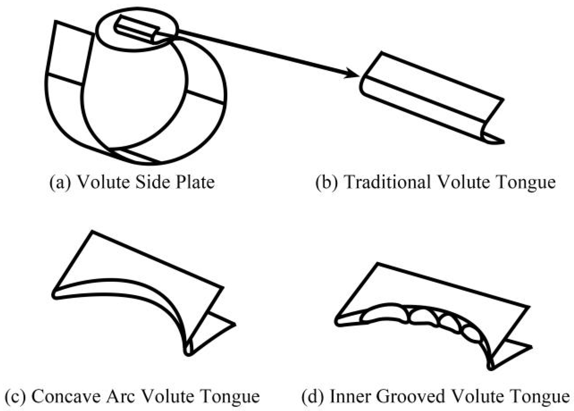
27] take the spiral angle of the starting and ending position of the volute profile as the design parameter to optimize the structure of the volute. The numerical simulation results show that the efficiency of the fan decreases slightly and the noise of the fan decreases. On the contrary, on the basis of fully studying the flow around the volute tongue by means of experiment and simulation, some scholars have made great improvements to the structure of the volute tongue. Liu et al. [
28] design a concave volute tongue and apply it to a multi-wing centrifugal fan of a range hood (
Figure 1). Its effect is verified through experiments and simulations, and the results show that the volute tongue design can reduce the noise of the fan by about
dB. In addition, the concave volute tongue can increase the flow area of the fan outlet, so the flow rate of the fan is increased. Therefore, in the design, the flow area near the tongue should be appropriately increased to improve the flow quality of the volute. Dong et al. [
29] apply the profile structure of the leading edge of the owl wing to the volute tongue of a multi-wing centrifugal fan and conduct numerical simulation of the fan model with different volute tongue installation angles under different flow conditions. The research shows that the design could improve the aerodynamic performance of the fan under different flow rates. Liu et al. [
30] apply the wave front structure of humpback whale flippers to the optimal design of the volute tongue of a multi-wing centrifugal fan, establish a three-dimensional wave front airfoil with different wave direction angles, and propose an optimal design method for the volute tongue optimization. The results show that when the wave direction angle is
, the generation of separation vortex and the shedding of wake vortex can be effectively inhibited, which is helpful to reduce the noise. The static pressure recovery coefficient is about 5% higher than the original fan, the air volume is
% higher, and the noise is reduced by
dB. The results show that a reasonable volute tongue radius and spiral angle can improve the gas flow state near the volute tongue, reduce the influence of eddy flow and reflux on aerodynamic performance, and improve the performance of the centrifugal fan. Therefore, the design of the volute tongue structure plays an important role in affecting the aerodynamic performance and noise of the fan.
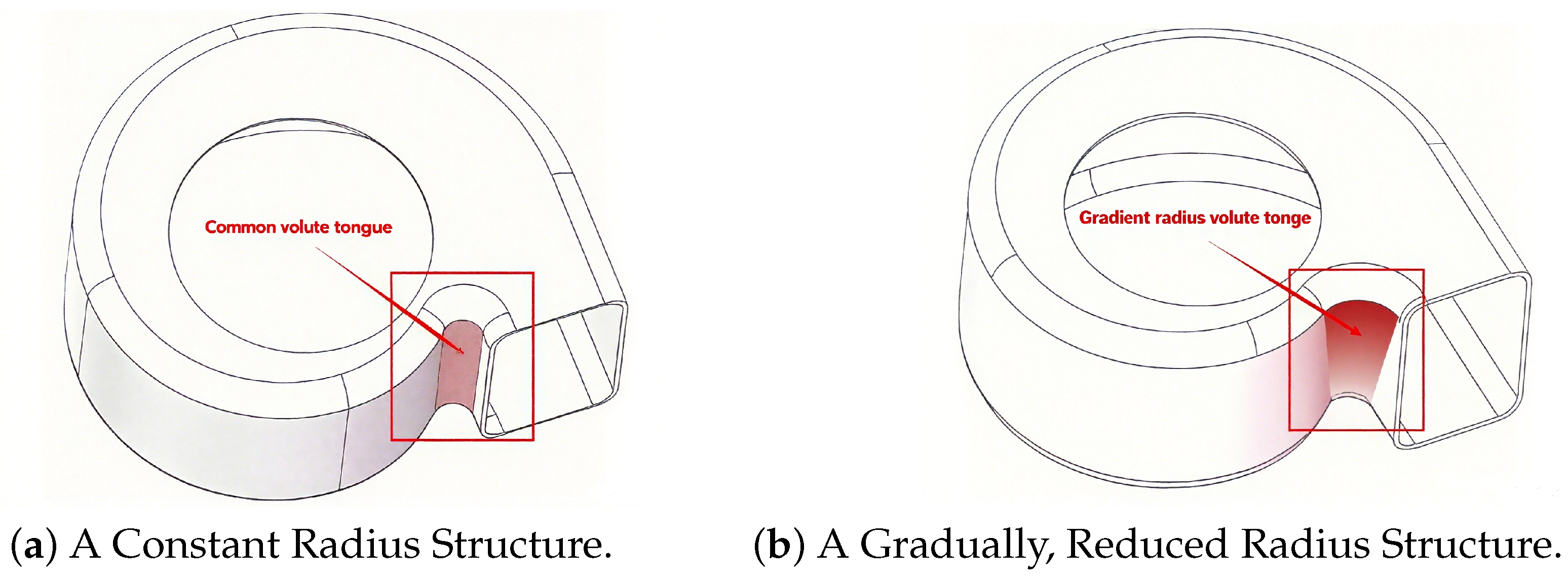
Considering the above problems, this paper establishes a simulation calculation model of a multi-wing centrifugal fan with a gradient-radius volute tongue based on the Realizable turbulence model and the FW-H equation. The fan flow field adopts a Realizable turbulence model, which adapts to the flow field of rotating machinery to obtain an accurate internal flow of the fan, and fan noise is solved by the acoustic analogy method. Based on the FW-H equation, the sound field information obtained from the flow field calculation is input into the far-field wave equation, and the noise data of the measuring point is obtained by integration. Then, the fan is modeled and numerically simulated, and the calculation results are analyzed. The reliability of the simulation method is verified by comparing the performance data of the fan obtained by the test. Then, the tongue structure of the fan is adjusted; the gradient-radius volute tongue is designed; and the pressure analysis, flow loss analysis, and noise analysis of the fan basin before and after optimization are carried out. Compared with the prototype fan, the noise of the fan decreases by 3.5 dB, which is beneficial to the noise reduction of the fan during operation.
The structure of this paper is organized as follows:
Section 2 presents the calculation equations related to the aerodynamic performance of the fan and carries out the modeling and numerical simulation,
Section 3 designs the gradient-radius volute tongue structure and analyzes how the fan aerodynamic performance changes, and
Section 4 concludes this study.
3. Analysis of Influencing Factors of Aerodynamic Performance and Noise of Fan
Based on the theoretical analysis, test, and simulation calculation above, this chapter proposes the parameter scheme of the gradient-radius volute tongue and studies the aerodynamic performance and noise changes of the fan by adjusting different parameter schemes and the causes. In order to ensure that the study parameters vary within a reasonable range and avoid the deterioration of the flow field inside the fan, which may lead to performance degradation and noise increase, this paper made reference to relevant literature and fan design manuals, as in [
34], and finally determined the scheme shown in
Table 2.
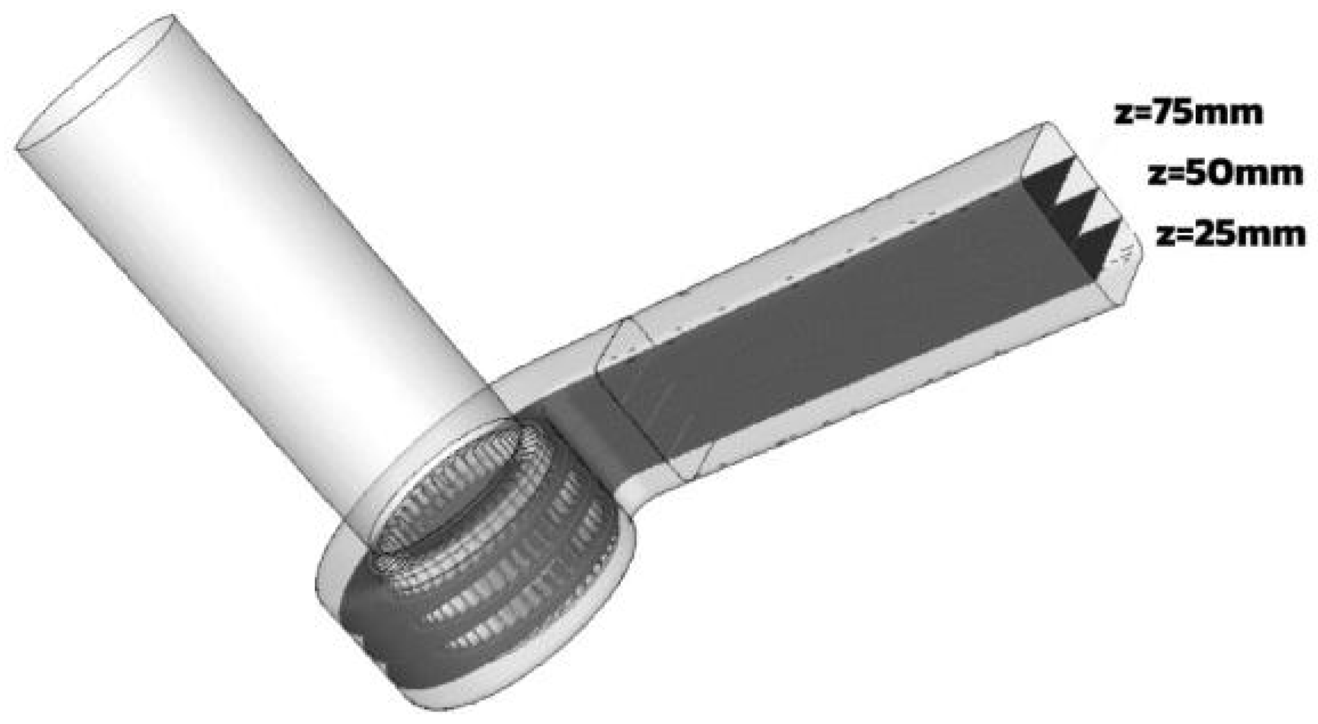
Due to the asymmetry of the axial flow field of the fan along the blade wheel, in order to facilitate the analysis of the flow field and noise characteristics at different heights along the axis after the structural parameters are changed, three cross sections are divided, which are, from top to bottom, side section of the front disk (75 mm), middle section (50 mm), and side section of the rear disk (25 mm). The angle division rule is used in the analysis of flow field and sound field. The fan section division is shown in
Figure 8.
3.1. Fan Basin Pressure Analysis
The volute plays a role in transforming the gas dynamic pressure energy into static pressure energy, so the static pressure can directly reflect the influence of the gradient-radius volute tongue structure adjustment on the volute workability.
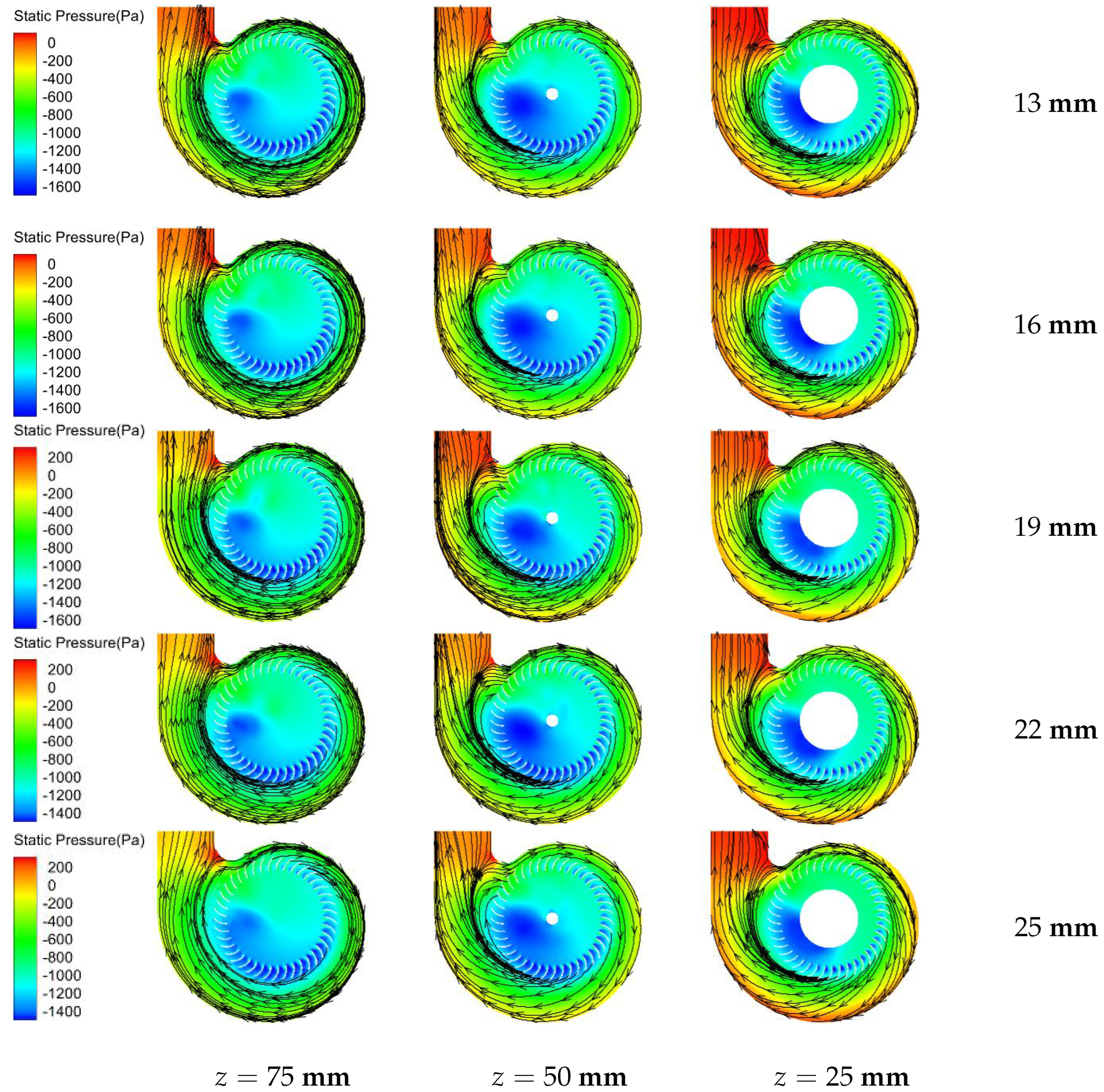
Figure 9 shows the cloud diagram of the static pressure-flow line distribution of each section of the volute tongue fan basin with different gradient-radius. When the radius of the volute tongue on the front disk side is increased, the static pressure near the volute outlet decreases compared with that of the original fan, and the decrease becomes more obvious with the increase, but the static pressure distribution at the outlet is more uniform. The high static pressure area is mainly concentrated in the vicinity of the volute tongue near the outlet, which is conducive to weakening the unsteady flow caused by the pressure gradient, reducing the noise, and improving the flow quality of the fan.
According to the flow line distribution on the front panel side, after the static pressure at the outlet drops the air backflow phenomenon caused by the pressure gradient is weakened compared with the original fan, so the interference of the leaf outflow is weakened and the flow loss near the volute tongue is reduced. In the middle disk position, the return flow of the volute tongue in some schemes increases, which is speculated to be because the change of the radius of the volute tongue does not match the exit angle of the original fan blade, resulting in an increased angle between the airflow direction and the volute tongue, and more air is returned to the impeller basin through the volute tongue. At the rear disc position, because the radius of the volute tongue is close to that of the original fan, the flow situation is basically unchanged.
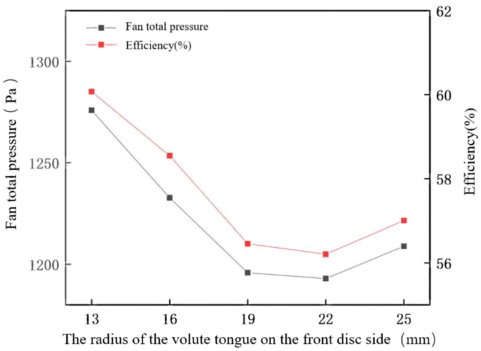
Figure 10 depicts the relationship between radius and total pressure as well as pressure-efficiency, which describes the influence of volute tongue with gradient-radius on aerodynamic performance. According to the change curve of total pressure-efficiency of the fan (
Figure 10), although the gradient-radius volute tongue design can reduce the noise of the fan, it will lead to the decrease of the aerodynamic performance of the fan. The aerodynamic performance of the 22 mm scheme is the worst, and the total pressure and efficiency are reduced by
Pa and
, respectively. The reason for this is that after improving the structure of the volute tongue, corresponding adjustments are needed, such as other structural parameters of the fan, such as the impeller outlet angle, so as to improve the matching degree between the wind dynamic structure and the static structure and improve the aerodynamic and noise performance of the fan.
3.2. Analysis of Flow Loss in Fan Basin and Around the Tongue
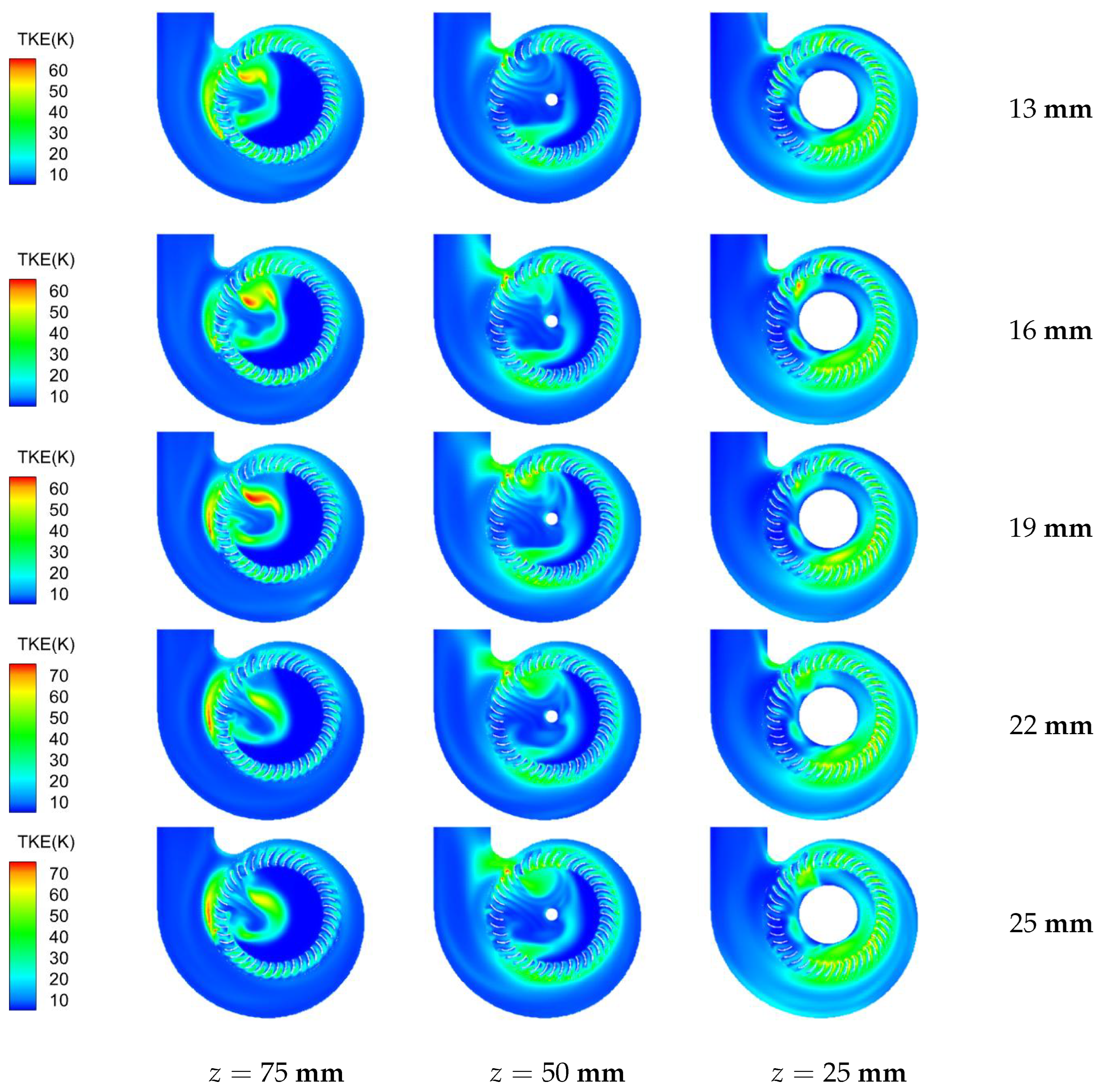
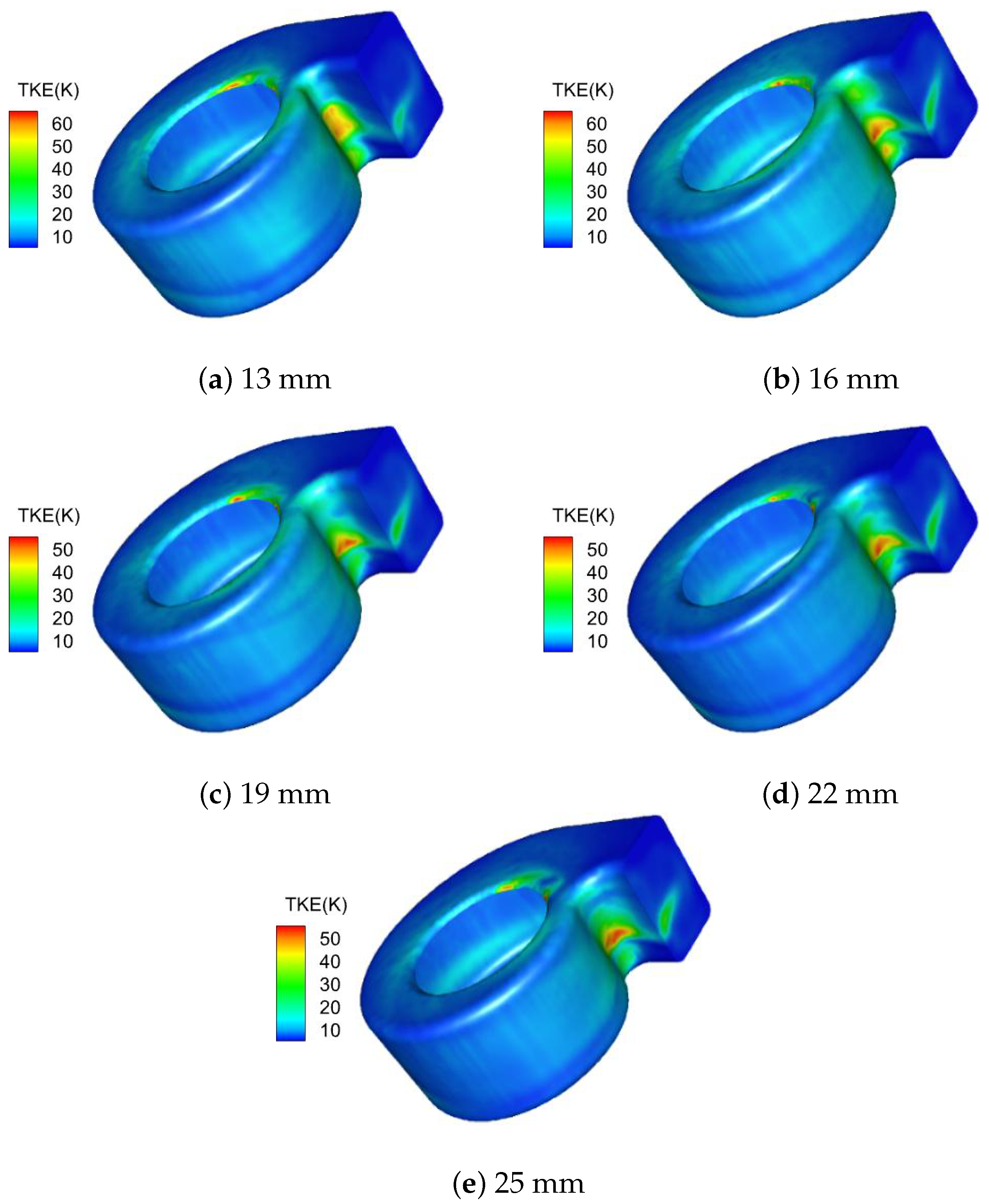
Figure 11 shows the distribution of turbulent kinetic energy with different gradient-radii. According to the
mm cloud image, when the radius of the volute tongue on the anterior disk is increased, the turbulence loss at the position of the volute tongue is reduced, and the flow separation phenomenon in the nearby blade canal is significantly weakened, indicating that the mutual interference between the outflow flow and the return flow of the volute tongue on the anterior disk is reduced in the larger flow space, and the flow situation near the volute tongue on the anterior disk is improved. In addition, the increase of the volute tongue clearance also buffers the high-speed airflow in the blade passage, thus reducing the impact on the volute. Although the area of the high turbulent energy area in the upper part of the volute tongue expands along the axial direction of the volute tongue, the area in the transverse section is significantly reduced, and the average value is lower than that of the original fan, indicating that the gradient-radius design has a better performance in the front disk.
According to the turbulent energy cloud diagram of the middle section
mm), the flow position in the middle of the impeller and volute is not significantly improved after adjustment, but the flow loss near the volute tongue is intensified, that is, a high turbulent energy area is formed with the volute tongue as the center and extended to the outlet of the volute and the impeller blade channel, respectively. However, according to
Figure 10, the peak value of turbulent energy in the middle of the improved volute is lower than that of the original fan, in which the scheme of
mm is about
K lower than that of the original fan, and the scheme of 19 mm is about 3 K lower than that of the original fan. If the value
continues to increase, the peak value of turbulent energy does not decrease significantly. According to the analysis in the previous section, the reason for this phenomenon is that the improved volute tongue does not match the original impeller, resulting in a new turbulent zone. Therefore, when improving the fan, it is necessary to pay attention to the coordination between multiple parameters in order to achieve the best overall working performance.
Compared with the flow conditions of the posterior disk before and after the improvement, it is found that the high turbulent energy area of the tongue narrowed and the flow loss of the blade channel decreased or even disappeared in the range of 0–
, while the flow condition of the impeller basin in the range of 45–
deteriorated because the turbulence in the middle region of the impeller extended to the impeller’s posterior disk, causing interference to the inlet air of part of the blade channel. Then, secondary flow is generated in the blade channel, which induces flow separation and interferes greatly with the mainstream. According to
Figure 11, different radii of the volute tongue have little influence on the flow near the volute tongue on the posterior disk side, and the turbulent kinetic energy at this position is all within 30 K.
3.3. Pressure Pulsation near the Volute Tongue and Fan Noise Analysis
To obtain pulsation information near the volute tongue, pressure pulsation curves of
and
monitoring positions at different heights are drawn, as shown in
Figure 12. Since
is closer to the impeller, there is an obvious pressure amplitude at the blade frequency, while there is a strong interaction between the blade outflow and the volute tongue structure at the M position, so there is also a wide frequency pressure pulsation near the blade frequency. After applying the gradient-radius volute tongue design, the pressure superposition effect near the volute tongue at different heights is weakened, and the amplitude of the wide frequency pressure pulsation is reduced compared with that of the original fan, and the effect becomes more obvious with the increase of the volute tongue design. At the wheel frequency position, increasing the radius of the volute tongue is conducive to reducing the pressure pulsation at the outlet of the volute, among which the scheme of 25 mm has the most obvious effect, and the amplitudes at
–
F,
–
M, and
–
R decrease by about 84 Pa, 60 Pa, and 16 Pa, respectively.
According to the pressure pulsation at the
position near the volute outlet in
Figure 13, the pressure pulsation at this position is mainly under the wheel frequency. Except for
–
M, the pressure pulsation at other positions is reduced because the turbulent energy area at the middle outlet of the volute is extended after the change of the volute tongue, which leads to the deterioration of the flow in this area and the increase of the amplitude of the pressure pulsation. For the front and back sides, the amplitude of pressure pulsation decreased to different degrees. Furthurmore, the analysis of the cases with different volute tongue radii in
Figure 13 indicates that at the P1 position, which is located near the impeller, both the blade frequency component and the broadband pulsation gradually decrease as the maximum radius of the front disc increases. At the P8 position near the volute outlet, the blade frequency pulsation is suppressed in most cases except for the middle section, with the front disc side being the most sensitive to variations. Among the tested configurations, the scheme with 22 mm exhibits the most effective pulsation attenuation.
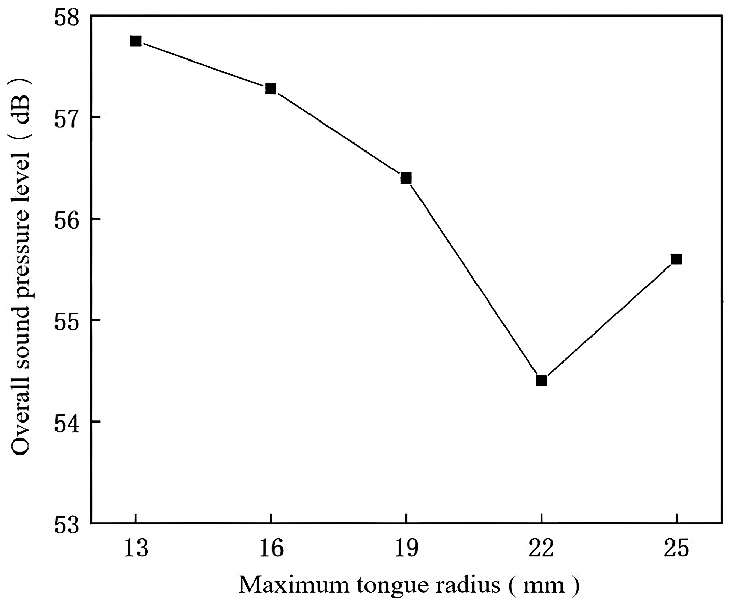
Figure 14 depicts the relationship between the radius and fan noise and describes the influence of volute tongue structure with gradient-radius on fan noise. According to
Figure 14, the design of the gradient-radius volute tongue has the effect of reducing the pressure pulses between the volute tongue and the airflow, which can significantly decrease the pressure pulsations generated by the interaction between the volute tongue and the airflow, and reduce the noise at the volute tongue position. Ultimately, this is beneficial for reducing the noise during the operation of the fan. The most effective noise reduction is achieved by the scheme with of 22 mm, and there is a
dB reduction in noise compared to the original fan.
3.4. Aerodynamic Noise Test
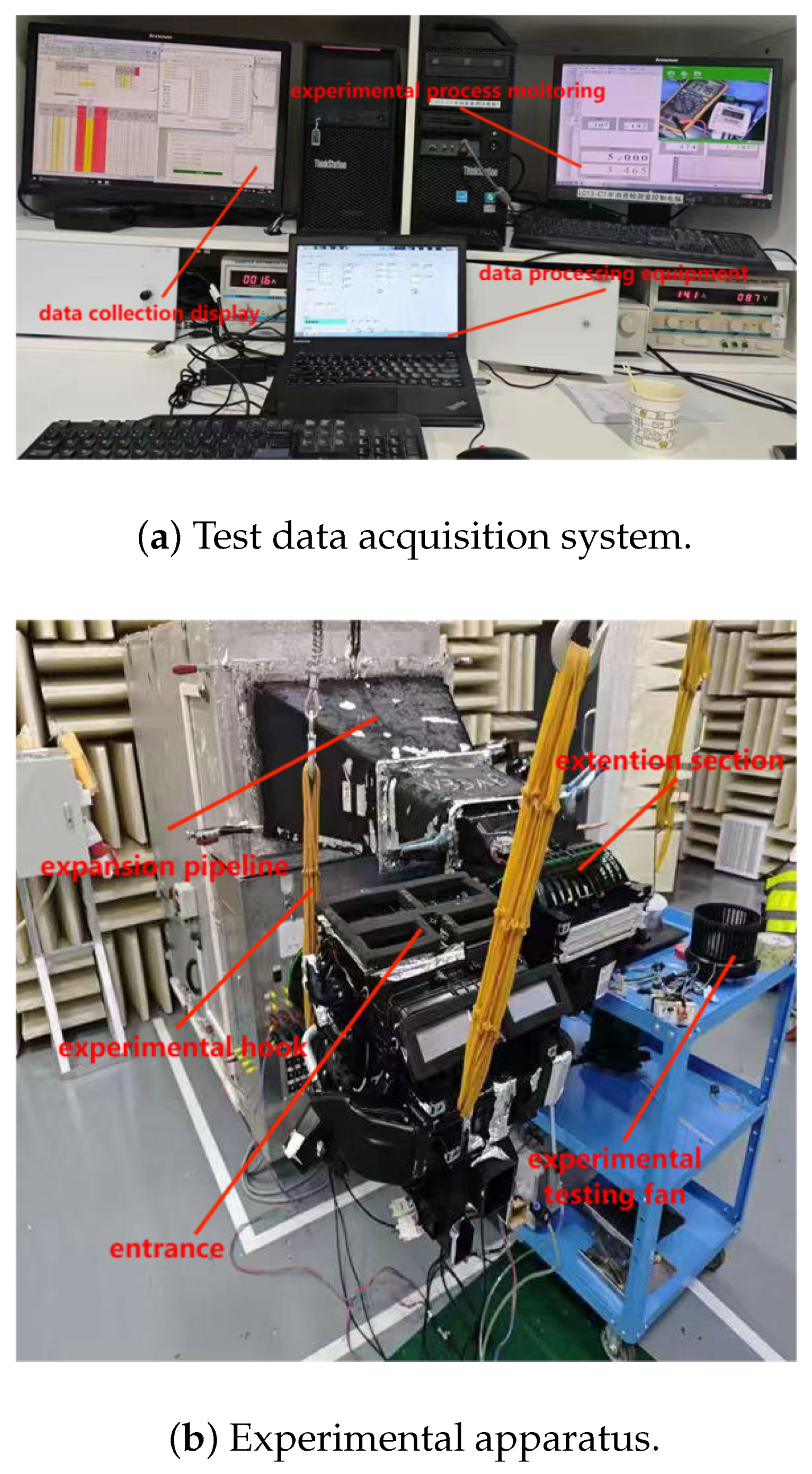
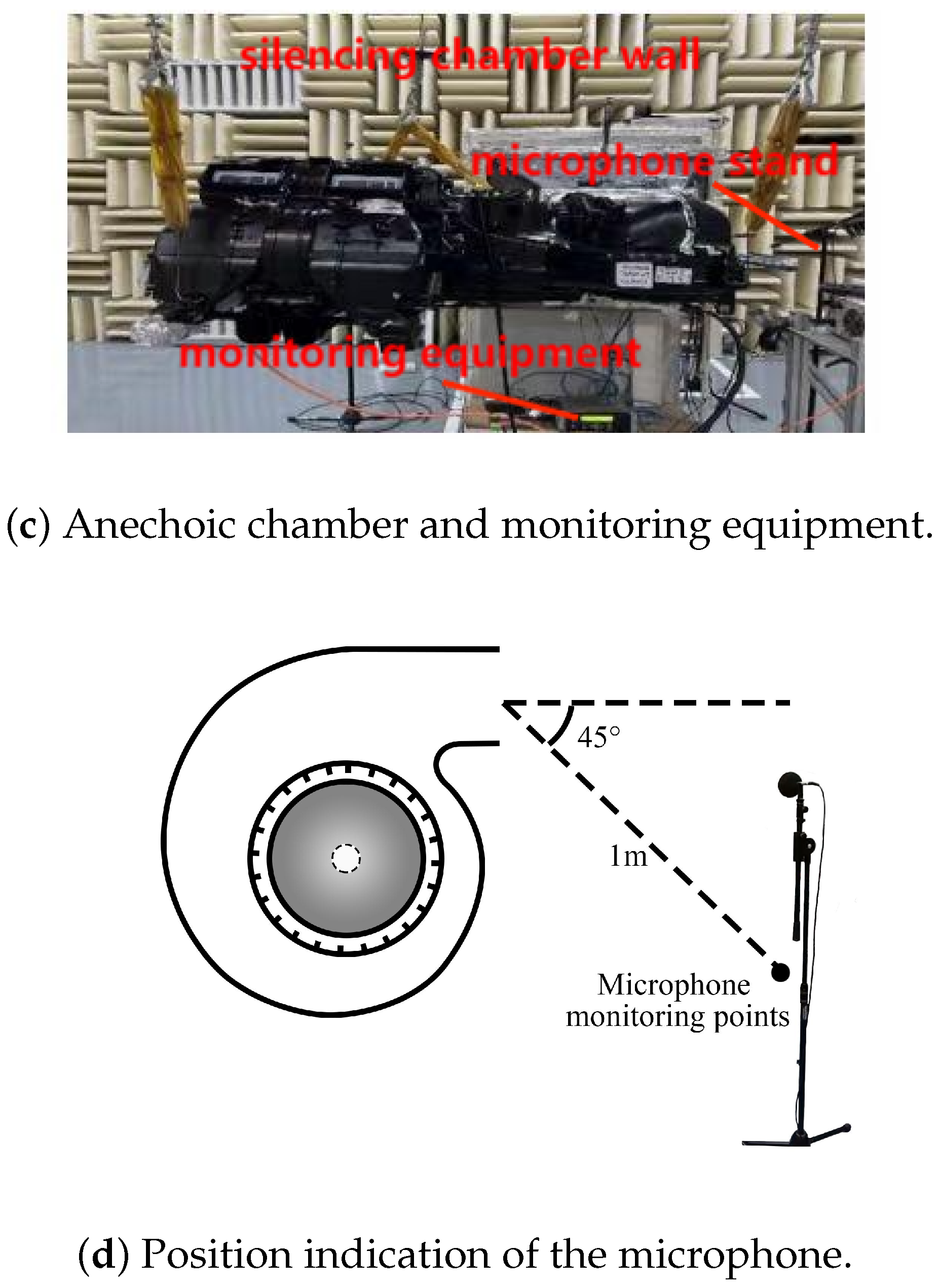
The aerodynamic noise test of the fan is conducted in a semi-anechoic chamber (
Figure 15a–c), where the indoor background noise is significantly lower than that of the centrifugal fan.
Figure 15a illustrates the test data acquisition system, which consists of the data acquisition and display unit (upper left), the data processing unit (center), and the experimental monitoring unit (upper right).
Figure 15b presents the experimental apparatus, including the expansion pipe, extension section, inlet, mounting hooks, and the test fan.
Figure 15c shows the anechoic chamber and monitoring equipment, including the chamber walls, microphone stand, and monitoring devices. The microphone used in the experiment is of the RST1000 model produced by Beijing Renshen Xinpu Company (Beijing, China). Its core specifications include sensitivity of 4 mV/Pa, frequency response range of 20 Hz–40 kHz with an error controlled within ±1 dB; the microphone head adopts a pre-polarized capacitive design, with a polarization voltage of 0 V, a dynamic range of 35–156 dB, a microphone diameter of 6.9 mm, an overall length of 65 mm. The computer used for processing data is equipped with a Windows 10 system and has a storage capacity of 512 GB. The specifications of the microphones used in the laboratory is shown in
Table 3. According to the testing standards provided in [
35], a monitoring microphone is placed at a position 1 m away from the fan outlet and at an angle of
to reduce the influence of the outflow air and motor noise on the test results.
The results of the fan noise test and simulation are shown in
Figure 16. The noise spectrum of the fan has both discrete characteristics and wide frequency characteristics, corresponding to the noise theory of the fan: the blades periodically beat air particles, and the blades periodically impact the inner wall of the volute, which are the main reasons for the discrete noise. The vortex noise caused by flow separation in the impeller region, the “jet-wake” phenomenon near the blade outlet, laminar flow on the wall, and turbulent boundary layer shedding are the main components of vortex noise, which has the characteristics of a wide frequency range.
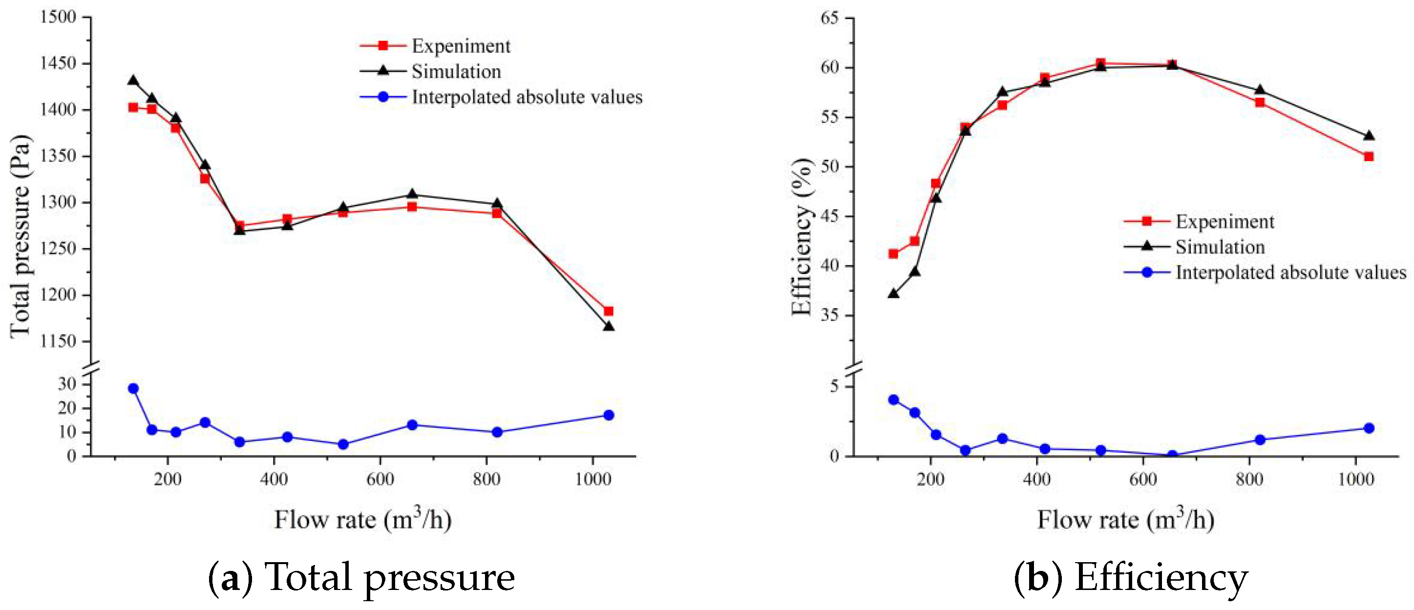
Comparing the test and simulation results of fan noise, it can be seen that there are some differences between the two. The reasons for the error are as follows: The mechanical noise and electromagnetic noise of the fan are not considered in the simulation, and the fan model is partially simplified before calculation. The maximum error at low frequencies reaches 35%, while the overall average error remains within 20%. Under rated working conditions, the simulated sound pressure level of the fan at the measuring point is dB, and the test sound pressure level is dB, with an error of dB, which is within the acceptable error range.
In general, the trend of the sound pressure level curve of the test and simulation results is basically the same, and the simulation results can better reflect the noise characteristics of the fan. Therefore, the model can be used for the subsequent noise calculation and analysis of the fan, and the rationality of the data simulation theory research on the gradient-radius volute tongue structure is verified. The design of the gradient-radius volute tongue structure can greatly reduce the pressure pulsation caused by the interaction between volute and air flow, and reduce the position noise of the volute tongue, which is conducive to noise reduction during fan operation.
