Abstract
Traffic-induced vibrations from road and rail systems pose a significant threat to the structural integrity and operational safety of buildings, especially masonry structures located near planned infrastructure such as tunnels. This study investigates the dynamic impact of such vibrations on a representative early 20th-century masonry building situated within the influence zone of a design railway tunnel. A comprehensive analysis combining geological, structural, and vibration propagation data was conducted. A detailed 3D finite element model was developed in Diana FEA v10.7, incorporating building material properties, subsoil conditions, and anticipated train-induced excitations. Various vibration isolation strategies were evaluated, including the use of block supports and vibro-isolation mats. The model was calibrated using pre-construction measurements, and simulations were carried out in the linear-elastic range to prevent resident-related claims. Results showed that dynamic stresses in masonry walls and wooden floor beams remain well below critical thresholds, even in areas with stress concentration. Among the tested configurations, vibration mitigation systems significantly reduced the transmitted forces. This research highlights the effectiveness of integrated numerical modelling and vibration control solutions in protecting structures from traffic-induced vibrations and supports informed engineering decisions in tunnel design and urban development planning.
1. Introduction
Traffic-induced vibrations, generated by the movement of vehicles on roads and railways, pose a significant threat to the structural integrity of buildings and the comfort of their occupants [1,2,3]. These vibrations, transmitted through the ground to the foundations, can lead to structural damage, like cracks in walls, columns, and ceilings, potentially resulting in building failures. Very often, buildings exposed to traffic-induced vibrations experience damage to non-structural (architectural) elements; for example, scratches on paint coatings, cracks and detachment of ceramic tiles in bathrooms, scratches on ceramic floor coverings, deepening of existing cracks and fissures, detachment of small fragments of internal and external plasters, detachment of poorly adhered ceramic tiles, detachment of damaged cornice fragments and poorly secured pinnacles, increased loosening of bricks in masonry chimneys, increased loosening of roof tiles leading to their slipping, intensification of cracks at the joints of structural elements (e.g., wall-ceiling in prefabricated buildings), especially those made of different building materials, and intensification of cracks at the joints of poorly executed gypsum board claddings [4].
Moreover, prolonged exposure to vibrations can negatively affect the health and well-being of people in buildings. Ensuring the safety of building use is crucial, especially in the context of dynamic impacts related to traffic movement.
Every day, buildings are subjected to various types of impacts. One of these is mechanical vibrations, which affect buildings throughout their entire period of use and can contribute to their excessive wear and, consequently, damage. What level of vibrations are buildings exposed to, how do these vibrations affect their structure, and how can the negative effects of vibrations be counteracted?
Traffic-induced vibrations, due to their repetitiveness, can also lead to a decrease in property value, which is particularly significant in areas with high traffic density. Building owners often have invested in costly renovation and modernisation works to mitigate these vibrations. In some instances, implementing specialised vibration-damping technologies—for instance, seismic isolators or vibro-isolation mats—becomes necessary, which can further escalate construction and maintenance costs. Therefore, designers and engineers need to consider these factors when planning and constructing new buildings and during the renovation of existing structures.
Reducing traffic-induced vibrations is crucial for protecting buildings and ensuring occupant comfort [3,5]. Popular methods include vibration isolation with polyurethane or rubber mats, appropriate building design, green barriers, infrastructure maintenance, and vibration monitoring [6].
Vibro-isolation mats are commonly used beneath road and rail surfaces as well as under building foundations. In railway systems, encapsulated rails or block supports in encapsulation can further reduce vibrations. The design process of new buildings should consider the impact of vibrations at an early stage, with careful selection of construction materials and techniques to limit transmission. In large urban areas, green tram tracks filled with vegetation also help to reduce vibration levels. Regular maintenance and modernisation of roads and railway tracks are essential for ensuring smoothness and stability, which in turn decreases the intensity of vibrations affecting nearby structures.
Modern monitoring systems allow rapid detection of vibration intensity in buildings, enabling timely responses to potential risks. Vibration assessments are vital for identifying appropriate protective methods. Isolation can be active (separating the vibration source from its surroundings) or passive (limiting transmission from the ground to the structure). The most effective results are often achieved through structural modifications introduced at the design stage. Measures to reduce road traffic emissions include removing stormwater drains from carriageways and imposing speed limits. For railways, track grinding, lubrication, and ecological grass-filled tracks are frequently applied.
Comprehensive assessments rely on computer models that simulate structural behaviour under predicted or measured vibrations [4,7,8]. This approach provides precise inertial force values and allows verification of structural strength. Approximate assessments, often applied during renovation, involve determining maximum acceleration, velocity, or displacement values at the foundation or ground level.
This paper evaluates the dynamic effects of vibrations on buildings and presents selected protective technologies to mitigate their impact. The final section is devoted to numerical analysis performed in the Diana 10.7 software environment. The study discusses the causes and consequences of traffic-induced vibrations, methods of measurement, and strategies for mitigation. Examples of modern technological solutions are also presented. The analyses were carried out within the linear-elastic range, with the aim of preventing potential claims from residents due to risks of structural damage.
The scope does not cover the impact of vibrations on the human body, although prolonged exposure is known to cause fatigue and reduce quality of life.
Representative buildings of different heights and materials were analysed, taking into account their service life and technical condition. Pre-construction vibration measurements were used to calibrate building models. A propagation model traced vibrations from the planned underground rail tunnels through the ground to the structures. Excitation forces were based on predicted train passages, enabling the assessment of vibration impacts on various structural elements.
The novelty and significance of the research presented in the article can be summarised as follows:
- Comprehensive Analysis of Traffic-Induced Vibrations: The study provides an in-depth analysis of the causes and effects of traffic-induced vibrations on buildings raised with materials with different mechanical properties, highlighting the potential structural and non-structural damages;
- Impact on Building Integrity: It emphasises the significant threat these vibrations pose to the structural integrity of buildings;
- Vibration Propagation Model: The use of a vibration propagation model from the track system in the designed tunnel to the building, considering ground conditions, is a notable aspect. This model helps in determining the vibration components affecting the building models;
- Pre-Construction Vibration Measurements: The calibration of building models using pre-construction vibration measurements adds a layer of precision to the analysis;
- Mitigation Strategies: The paper discusses various strategies to mitigate the effects of vibrations, including the use of vibro-isolation mats, green tracks, and modern monitoring systems;
- Numerical Analysis: The inclusion of numerical analysis in the Diana environment to assess the impact of dynamic actions on building constructions is a significant contribution.
2. Selected Representative Building
The building selected for analysis is considered as representative of masonry structures located within the dynamic influence zone of the analysed tunnel section. Analysed development consists of two parts, each composed of two segments. The part located above the tunnel comprises segments A and D, while the part situated outside the tunnel consists of segments B and C—see Figure 1. Each segment was constructed in 1930 using traditional masonry techniques. Spatial rigidity is ensured by a transverse–longitudinal arrangement of load-bearing walls. Each segment was directly founded on brick footings at a depth of 1 m.
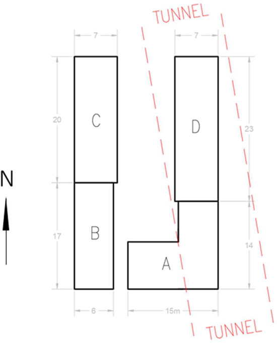
Figure 1.
Location of the building in relation to the axis of the planned tunnel.
Segments A, B, C, and D have the following dimensions in plan view: 14 × 15 m, 6 × 17 m, 7 × 20 m, and 7 × 23 m, respectively. The segments differ in height and number of floors. The heights of segments A, B, C, and D are 6.4 m, 5.5 m, 13.2 m, and 13.2 m, respectively. The number of floors varies as follows: segment A has 1 floor with an unused attic, segment B has 1 floor with an unused attic, segment C has 3 floors with a usable attic, and segment D has 3 floors with a usable attic. The ceilings in all segments are made of wooden beams. In staircases within segments C and D, the ceilings are arched vaults. Segments A, B, C, and D lack a perimeter ring beam; however, in segments C and D, anchor ties reinforce the load-bearing walls. In segments A and B, the stairs are wooden, whereas in segments C and D, they have a mixed construction—concrete on steel beams, with the top floor featuring wooden stairs. The roof structure is wooden over all segments. Above segments B, C, and D, the roof is single-pitched, while above segment A, it is gabled with a partial single-pitched section. Segments A and D of the building are located directly above the tunnel. The thickness of the soil above the tunnel is approximately 12.7 m, which is equal to the diameter of the TBM tunnel.
3. Ground and Water Conditions in the Building Area
The closest geological borehole to the building is Bo01. Geological and engineering investigations have shown that the lithographic cross-section is varied—see Table 1. The soils present in borehole A differ in lithology and, consequently, in geotechnical parameter values. In this profile, the following geotechnical layers can be distinguished—see Table 1.

Table 1.
Geotechnical layers in geological borehole Bo01.
In geological borehole no. Bo01, the drilled and stabilised water level is at 5.00 m below ground level. Additionally, another drilled water level is at 22.4 m below ground level. Dynamic analyses also incorporated data from subsoil investigations, including SBT (seismic borehole tomography) probing, down-hole testing, laboratory tests, and CPTu (Cone Penetration Test with pore water pressure measurement) probing. Table 1 provides information about the soil type. The analyses included data from the SBT seismic survey and CPTu probing.
4. Methodology and Numerical Analyses
The building is a spatial structure, and therefore it was decided to analyse it as a whole using a 3D spatial model—see Figure 2. The dynamic model of the building was constructed using the Finite Element Method (FEM) software Diana FEA [9].
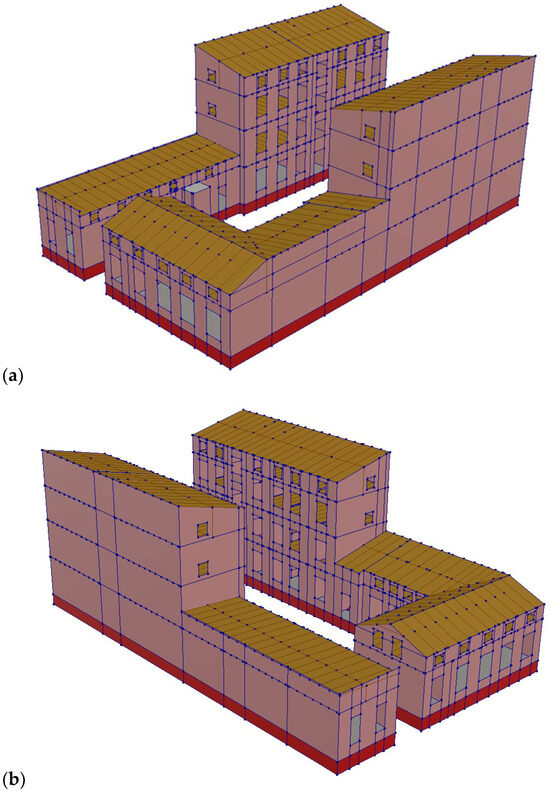
Figure 2.
Visualisation of the FEM computational model of the analysed building: (a) South East view, (b) South West view.
For the entire building structure, global damping was assumed with a critical damping fraction ξ of 5.0%, which corresponds to masonry buildings in accordance with Eurocode 8 [10]. The calculations accounted for the self-weight along with live loads (in standard dimensions, reduced to 40% of characteristic values according to the Polish Code PN-B-02170:2016-12 [11]) uniformly distributed over the surface of horizontal partitions. The analysis was conducted using characteristic values of loads and sectional forces. The values of dead and live loads were determined based on the building’s structural description. The calculations were performed using the direct integration method of motion equations with an integration step of ∆t = 0.002 s, which corresponds to signal sampling at 500 Hz. The structural FEM model used for the analysis is shown in Figure 2.
The materials used in the constructed dynamic model of the building are listed in Table 2. In the calculations, the following values for live loads were assumed:

Table 2.
The most important parameters (properties) of analysed structure.
- In residential rooms: 1.50 kN/m2;
- On staircases: 3.00 kN/m2.
The average weight of floor layers was assumed to be 1.3 kN/m2.
Structural elements such as beams and columns were modelled using beam-type finite elements (two-node finite elements with six degrees of freedom per node), while surface elements like walls and floors were modelled using shell elements (four-node or three-node finite elements with six degrees of freedom per node).
4.1. Verification of the Building Calculation Model
The FEM calculation model was verified based on empirical (simplified) formulas for wall buildings [12]. According to the research, the basic frequency of natural vibrations can be determined based on the following equation:
F1 = 50/H [Hz],
In Equation (1), H is the height of the building from the foundation level in meters. In the analysed case, H is 14.6 m and the basic vibration frequency is 3.4 Hz for segments C and D (the same height). The first mode of natural vibrations calculated on the basis of the FEM model and the corresponding mode of natural vibrations for segments C and D are shown in Figure 3. Therefore, the difference in vibration frequency according to Formula (1) and FEM analyses is as follows: for segment C 9%, and for segment D 3%. Therefore, the computational model has been positively verified.
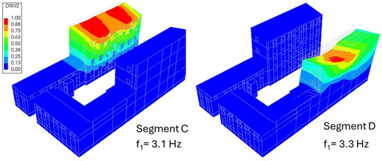
Figure 3.
The calculated base vibration modes for segments C and D calculated based on the FEM models.
4.2. Slab Track Construction and Adopted Vibration Insulation
In the case of rail traffic, loads are transferred at the wheel–rail interface. As a result, they are transferred through the track surface and substructure layers, through the tunnel lining, and then transferred through the ground to buildings, generating additional dynamic forces. This issue is particularly important because in many cases buildings (especially old ones) were not designed for such impacts in the past. Therefore, to minimise dynamic impacts, the simplest method is to introduce vibration isolation at the source of vibration. One possible solution is to use a vibration isolation mat under the track surface or substructure. As a result, some of the mass is separated (unspring), and the dynamic characteristics of the track surface are changed (the natural frequencies are lowered, cutting off the higher frequencies associated with rail traffic). This reduces the vibrations transmitted further along the propagation path described previously.
The simulation analyses assumed a track design with a block support system embedded in the track slab surface through a flexible polymer resin layer. Additionally vibration-isolating mats were used under the track slab, with a thickness (stiffness) selected based on numerical analyses to ensure that the vibration influence on people is below the comfort threshold.
For dynamic calculations, a railway track structure was adopted using block supports. For the operational conditions anticipated for the analysed tunnel solution, supports with medium static stiffness were assumed at 60 cm intervals. To assess the effectiveness of the proposed vibration isolation solutions, dynamic calculations were considered in three variants:
- Variant 1: block supports without a vibration isolation mat;
- Variant 2: block supports with a vibration isolation mat placed directly under the main track substructure (track slab);
- Variant 3: block supports with a vibration isolation mat placed directly under the auxiliary substructure (concrete base), with the mat extending beyond the embankment onto the tunnel structure.
The variant analysis aimed to select optimal vibration isolation solutions for different sections of the analysed track system, taking into account technological feasibility. Calculations were performed for a single-nave, double-track tunnel. Selected segments of computational models of the track, incorporating vibration isolation solutions in variants 2 and 3, are presented in Figure 4. In vibration propagation models, boundary conditions were included in the form of finite elements preventing wave reflection at the model edges. The object was subjected to dynamic forces generated by moving rolling stock, with the maximum allowable axle load according to the speeds of up to 100 km/h on one or two tracks. The tunnel structure and soil stratification were incorporated into the vibration propagation models. Material parameters for individual layers were adopted based on the geotechnical investigation. Simulation calculations aimed at selecting the vibration isolation mat parameters in the track structure were based on determining (from measurement results and simulation calculations) the kinematic excitation affecting buildings in each analysed variant. Subsequently, dynamic calculations were performed for the selected building to determine the impact of vibrations on its structure.

Figure 4.
Segments of FEM models for calculating vibration propagation from the planned railway line—single-nave, double-track tunnels.
In numerical analyses, the material parameter values of vibration isolation elements listed below were adopted.
Block support—medium stiffness:
- Static stiffness 30 kN/mm;
- Dynamic stiffness 45 kN/mm;
Vibration isolation mat, thickness 40 mm:
- Static stiffness modulus for a load of 0.02–0.10 MPa: 0.0125 N/mm3;
- Dynamic stiffness modulus for frequency 10 Hz: 0.0215 N/mm3.
The selected building is representative of the masonry buildings in the zone of dynamic influence from the tunnel.
4.3. Adopted Kinematic Excitation
The designed kinematic excitation, described in the time domain, was applied to the computational model at all points of the building’s foundation at the interface with the ground as a uniform excitation caused by future train passages in the tunnel. The tunnel structure is a reinforced concrete facility embedded in the ground. It is elastically supported, and the support stiffness values were calculated using soil parameter values. The vibration records were obtained based on the analysis of the vibration propagation from the railway track to the building’s foundation, taking into account the local ground conditions and the characteristics of the trains expected to operate in the tunnel and their speeds (up to 100 km/h), resulting in various frequencies of excitation forces.
The waveform of the horizontal and vertical components x, y, and z of the generated vibration accelerations of building foundation originating from passages of trains and strong motion duration of analysed records with FFT is presented in Figure 5 and Figure 6. The maximum values of the x, y, and z components are small. The maximum acceleration values in the horizontal directions, x and y, are approximately 1 cm/s2 and 3.3 cm/s2, respectively. The maximum acceleration of the vertical vibration component is about 2 cm/s2. The duration of the intensive phase of the x, y, and z components of vibration acceleration does not exceed 8 s, amounting to approximately 7.5, 6.6, and 7.2 s, respectively—see Table 3. The results of the FFT analyses of the horizontal x and y components of vibration accelerations indicate that dominant frequency bands in the horizontal components x and y range from 37 to 50 Hz. In components x and y, higher dominant frequencies of 55 and 63 Hz can also be distinguished. In the vertical component z of vibration acceleration, the dominant frequency band is slightly wider than in the horizontal components x and y, spanning from 32 to 57 Hz—see Figure 6 and Table 3.
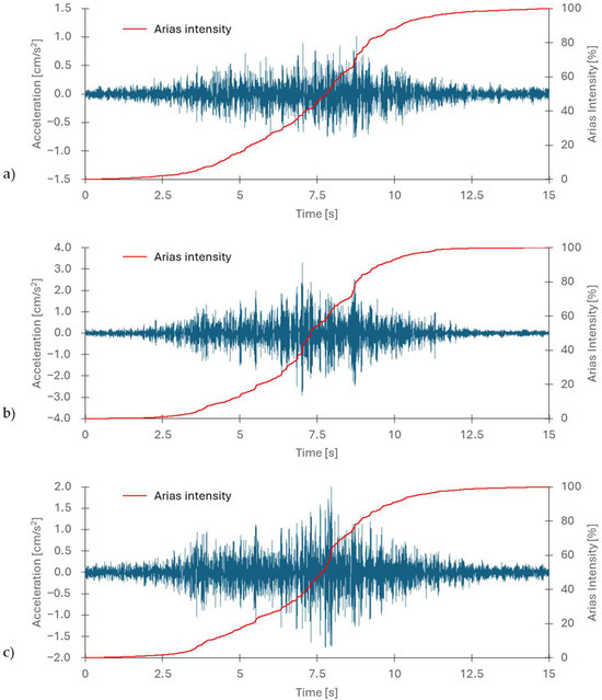
Figure 5.
Horizontal x, y (a,b), and vertical z (c) components of the calculated acceleration records.
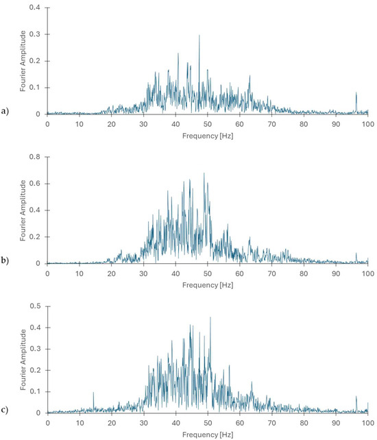
Figure 6.
FFT analyses of the horizontal x, y (a,b), and vertical z (c) components of calculated acceleration records from Figure 5.
4.4. Results of Simulation Calculations and Discussion
The results of dynamic calculations conducted using direct integration of the equations of motion are presented as envelopes covering the entire time domain of the event. The paper presents the results for the selected final solution with a vibration isolation mat located under the sub-base. This solution facilitated the execution of the concrete subgrade layer using the slipform method, significantly speeding up construction work. This solution is an alternative to the most commonly used solutions in the form of a vibration isolation mat located directly under the track slab. The solution has proven to be equally effective, while also being faster to implement. The results are presented for wooden ceiling elements (beams) and masonry walls. Due to the type of interaction, these elements are most critical to the safety of the structure. The envelope of bending moments in the wooden beams is shown in Figure 7. The maximum values of bending moments do not exceed 21 Nm. This translates into small bending stresses in the wooden beams, approximately 11 kPa. The calculations confirm that dynamic interactions have no effect on the supporting structure of the wooden ceilings. Moreover, the highest stress is incidental, lasting less than 1 s. Figure 8 shows a graph of the variation of the bending moment at a selected point (the mid-span of the wooden beam) during the train’s passage.
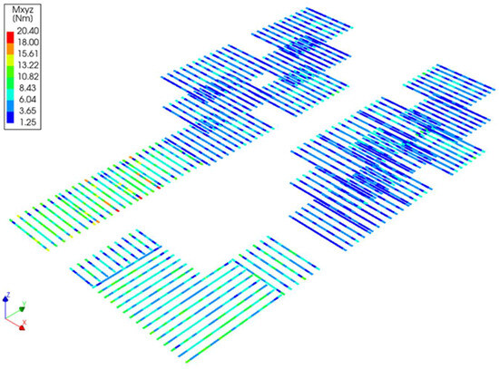
Figure 7.
Bending moment envelope in wooden beams.
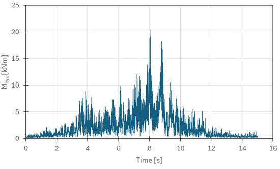
Figure 8.
Time history of bending moment at a selected point (the mid-span of the wooden beam).
In the case of dynamic stresses in masonry elements, it should be noted that the stress level is low (see Figure 9). For horizontal stresses YZ and XZ, the extreme values do not exceed 1.7 kPa. The obtained value can be positive or negative due to the significantly variable excitation. These values are not significant compared to the minimum standard shear strength of masonry along bed joints. For comparison, a brick wall with cement-lime mortar has a minimum wall strength of 200 kPa. Of course, this value also depends on the compressive stress and may be higher. Therefore, there is no risk of damage to the masonry structure due to shear stress. For vertical stresses occurring perpendicularly to bed joints, the values do not exceed 1.3 kPa. This is also a small value compared to the compressive stresses occurring from the dead weight, which can reach up to 1.0 MPa, which completely compensates for the additional dynamic stresses, which are tensile in nature. In such a situation, there is no risk of tensile stresses arising from the combination of permanent and dynamic loads. The situation is somewhat different in specific locations, such as the corners of window or door openings. There, the stress concentration and the complex direction of the principal stresses can lead to greater stress on the wall in this area. However, this does not completely affect the structural safety of the entire building.
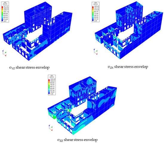
Figure 9.
Envelope of global (+) stresses in masonry walls.
The analyses conducted by the authors in this publication were limited to the specific geotechnical conditions and the specific dimensions of the TBM tunnel. These parameters can significantly influence the obtained results, as confirmed by the work presented in [13], among others. In the future, the authors plan to expand the calculations to include other ground conditions. However, the presented FEM approach is consistent with similar analytical studies in this area, such as [14]. The authors of this publication used a 3D approach, which is computationally time-consuming but yields better results than similar 2.5D or 2D approaches [15]. The linear-elastic modelling approach is justified by the goal of avoiding overestimation of resident-related claims, it might under-represent potential long-term degradation effects or performance under exceptional vibration events. In the future, it is necessary to verify the obtained results based on in situ tests after the tunnel is constructed and operated, as the authors plan.
5. Conclusions
The analyses were performed in the linearly elastic range. This was due to the attitude of the residents. Their position did not allow for damage to occur. The occurrence of damage could lead to a claim from the residents after the trains in the tunnel were started. A numerical FEM model of a representative masonry building was proposed.
The courses of horizontal components x, y, and the vertical component of vibration accelerations, which constituted the kinematic load, were generated. The planned speeds of trains in the tunnel were used, as well as parameters describing lithographic layers occurring on the way of vibration propagation from the railway track to the building foundations.
Variants of possible vibration isolation solutions were analysed. The obtained stress values in the structural elements, i.e., in the masonry walls and ceiling beams, are small and indicate that the building will not experience conditions that would threaten the safe use of the building.
For masonry buildings of similar construction located within the dynamic impact zone of a railway line running through a tunnel, the impact on the structure is minor. This is particularly true when the tunnel is equipped with vibration isolation in the form of block supports and vibration isolation mats.
Another important aspect mentioned in the paper is the issue of implementation time and cost. The solution finally chosen, a vibration-isolating mat under the sub-base, significantly shortened the construction time of these layers thanks to the use of dispersed reinforcement and the slip-cast method.
The paper identifies a problem that should be addressed in the future. This particularly concerns the analysis of possible solutions for minimising vibrations. Currently, the dominant solution is a vibration-isolating mat under the track slab. Other solutions are possible that optimise the use of vibration-isolating materials. The proposed solution is effective in application, but it requires the use of more material than, for example, linear or point supports. Rail fastening systems still offer significant potential. Equally important is minimising the impacts on vehicle structures, as analysed in [16,17]. Future work is planned to integrate the vehicle model with the track bed and vibration emissions to buildings. According to the authors of the above article, further analysis should focus on these solutions. This issue is becoming particularly important due to the expansion of underground transportation systems worldwide, which causes vibrations on the surface. This topic has recently become very important [18,19]. The investment is currently underway, and once completed, a cost analysis of the entire project will be possible. This element should also be subject to future analysis. It will also be possible to analyse the costs of increased expenditure on vibration isolation solutions and the possibility of demolishing the facility.
Author Contributions
Conceptualisation, F.P., T.T. and W.A.; methodology, F.P. and T.T.; software, F.P. and W.A.; validation, F.P. and T.T.; formal analysis, F.P. and T.T.; investigation, F.P. and T.T.; resources, F.P. and T.T.; data curation, F.P. and W.A.; writing—original draft preparation, F.P. and T.T. and W.A.; writing—F.P. and T.T.; visualisation, F.P.; supervision, F.P. and T.T.; project administration, F.P. All authors have read and agreed to the published version of the manuscript.
Funding
This research received no external funding.
Institutional Review Board Statement
Not applicable.
Informed Consent Statement
Not applicable.
Data Availability Statement
The data presented in this study are available on request from the corresponding author.
Conflicts of Interest
The authors declare no conflicts of interest.
References
- Hunaidi, O. Traffic Vibrations in Buildings; Construction Technology Update No. 39; National Research Council of Canada, Institute for Research in Construction: Ottawa, ON, Canada, 2000. [Google Scholar] [CrossRef]
- Lozančić, S.; Penava, D.; Klečina, M.B.; Jurić, A. A case study on influence of traffic-induced vibrations on buildings and residents. Acta Tech. Corviniensis 2019, 12, 15–18. [Google Scholar]
- Erkal, A. Impact of Traffic-Induced Vibrations on Residential Buildings and Their Occupants in Metropolitan Cities. Prome Traffic Transp. 2019, 31, 271–285. [Google Scholar] [CrossRef]
- Beben, D.; Maleska, T.; Bobra, P.; Duda, J.; Anigacz, W. Influence of Traffic-Induced Vibrations on Humans and Residential Building—A Case Study. Int. J. Environ. Res. Public Health 2022, 19, 5441. [Google Scholar] [CrossRef] [PubMed]
- Kowalska-Koczwara, A.; Pachla, F.; Burdzik, R. Research on Human Exposure to Transport-Induced Vibration in Buildings. Appl. Sci. 2024, 14, 9016. [Google Scholar] [CrossRef]
- Ren, S.C.J.; Fouladi, M.H.; Namasivayam, S.N.; Juen, H.H.; Baniotopoulos, C.; Tight, M.R. Anti-vibration slab mat to supress train track vibrations. J. Eng. Sci. Technol. 2016, 2018, 1–12. [Google Scholar]
- Takemiya, H. Environmental Vibrations: Prediction, Monitoring, Mitigation and Evaluation. In Proceedings of the International Symposium on Environmental Vibrations, Okayama, Japan, 20–22 September 2005. [Google Scholar]
- Chholak, K.; Dev, N. Computational Study of Vibration Mitigation by Slab Mat Layer in a Precast High-Speed Slab Track System. J. Vib. Eng. Technol. 2025, 13, 118. [Google Scholar] [CrossRef]
- Diana FEA. User’s Manual—Release 10.6; Diana FEA: Delft, The Netherlands, 2022. [Google Scholar]
- European Commission. Eurocode 8: Design of Structures for Earthquake Resistance—Part 1: General Rules, Seismic Actions and Rules for Buildings; European Commission: Brussels, Belgium, 2004. [Google Scholar]
- Polish Code PN-B-02170:2016-12; Evaluation of the Harmfulness of Buildings Vi-Brations Due to Ground Motion. Polish Committee for Standardization: Warsaw, Poland, 2016.
- Ciesielski, R.; Maciąg, E.; Tatara, T. Investigations of Buildings with Bearning Concrete Walls Subjected to Mining Shocks; Association Francaise pour la Construction: Paris, France, 1991. [Google Scholar]
- Gupta, S.; Stanus, Y.; Lombaert, G.; Degrande, G. Influence of tunnel and soil parameters on vibrations from underground railways. J. Sound Vib. 2009, 327, 70–91. [Google Scholar] [CrossRef]
- Forrest, J.A.; Hunt, H.E.M. A three-dimensional tunnel model for calculation of train-induced ground vibration. J. Sound Vib. 2006, 294, 678–705. [Google Scholar] [CrossRef]
- Lopes, P.; Costa, P.A.; Ferraz, M.; Calçada, R.; Cardoso, A.S. Numerical modeling of vibrations induced by railway traffic in tunnels: From the source to the nearby buildings. Soil Dyn. Earthq. Eng. 2014, 61–62, 269–285. [Google Scholar] [CrossRef]
- Yang, Y.; Liu, C.; Chen, L.; Zhang, X. Phase deviation of semi-active suspension control and its compensation with inertial suspension. Acta Mech. Sin. 2024, 40, 523367. [Google Scholar] [CrossRef]
- Liu, C.; Lai, S.-K.; Ni, Y.-Q.; Chen, L. Dynamic modelling and analysis of a physics-driven strategy for vibration control of railway vehicles. Veh. Syst. Dyn. 2025, 63, 1080–1110. [Google Scholar] [CrossRef]
- Zhou, Q.; Zhang, Q.; Sun, M.; Huang, X.; Huang, Z.; Wen, X.; Qiu, Y. Measuring Vibrations of Subway Tunnel Structures with Cracks. Buildings 2024, 14, 2660. [Google Scholar] [CrossRef]
- Li, D.; Li, Z.; Wang, H.; Yin, J.; You, Z.; Wang, F. Analysis of Environmental Vibrations in Suburban Railways Affected by Adjacent Bidirectional Tunnels. Appl. Sci. 2025, 15, 812. [Google Scholar] [CrossRef]
Disclaimer/Publisher’s Note: The statements, opinions and data contained in all publications are solely those of the individual author(s) and contributor(s) and not of MDPI and/or the editor(s). MDPI and/or the editor(s) disclaim responsibility for any injury to people or property resulting from any ideas, methods, instructions or products referred to in the content. |
© 2025 by the authors. Licensee MDPI, Basel, Switzerland. This article is an open access article distributed under the terms and conditions of the Creative Commons Attribution (CC BY) license (https://creativecommons.org/licenses/by/4.0/).
