Abstract
Auxetic structures, also known as metamaterials, exhibit a negative Poisson’s ratio under applied load and have found use across a variety of applications. This behavior may arise from material properties or from the structural design itself. Depending on the intended application, such structures can be subjected to either static or dynamic loading conditions. New geometries that potentially enhance energy absorption or damping in both static and dynamic conditions were investigated in this work, using the well-known Reentrant design reported in earlier research articles as a benchmark. As an alternative to the cellular limb angles employed in the well-known Reentrant model, the effect of radial limb radius was analyzed in the novel cell designs called Arched-Reentrant. Four alternative designs have been proposed, and all analyses were conducted in ANSYS-2025-R1. The specimens were manufactured by using the 3D printing method with thermoplastic polyurethane (TPU) material having a shore hardness of 95A. In the evaluation of the outcomes resulting from different designs, the specimens were analyzed under static, impulsive, and harmonic loading conditions. The energy absorption capacities of the samples were examined in relation to their design modifications. Within the scope of the study, it was observed that Arched-Reentrant structures are capable of absorbing higher amounts of energy under static loading and exhibit greater stiffness under dynamic loads compared to conventional Reentrant structures. The impulse analysis’s findings demonstrate that the suggested Arched-Reentrant-V3 model performs better, with over 50% less displacement and comparable reaction forces. In addition, the harmonic analysis findings show that the Arched-Reentrant-V3 model has lower ground reaction forces and displacement values. As a result, the suggested model can be regarded as an efficient damping component when dynamic loading occurs.
1. Introduction
Different damping element configurations are being studied to absorb the forces and vibrations that dynamic or static systems generate or are subjected to during operation, thereby preventing them from negatively affecting system outputs.
Specially designed raw-material architectures created using material technologies can yield auxetic materials with a negative Poisson’s ratio; additionally, non-auxetic structures may display auxetic behavior under loading due to their geometric design. Auxetic materials stand out in mechanically demanding design applications owing to their high impact resistance and energy dissipation capabilities. Compression or expansion along one axis causes a similar compression or expansion in the transverse direction in auxetic materials. The ratio of the transverse strain to axial strain or negative Poisson’s ratio characterizes this unique behavior. Among auxetic-design structures, the extensively studied Reentrant design derived from the honeycomb form has been shown to exhibit superior mechanical properties compared to the non-auxetic hexagonal structure (Figure 1) [1].
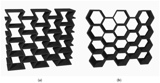
Figure 1.
Reference design. (a) Reentrant design structure. (b) Hexagon design structure.
The efforts to isolate the vibrations produced by mechanical systems during operation and thereby prevent their negative effects on system outputs are generally termed vibration isolation. Examples of such solutions include rubber mounts employed to dampen the amount of load transmission to the supporting structure generated during an engine block’s operation and seismic isolators employed to attenuate the effect of the ground excitations on the main structure. By leveraging different materials and design configurations, a variety of vibration-isolation methods can be implemented. Application specific requirements, available installation space, and cost considerations will ultimately determine which approach is most appropriate. In systems operating under static loads, it is expected that the damping structures absorb the energy generated under the applied force and, once that force is removed, revert to their original state; this cycle must be repeatable.
Materials or design structures that possess a negative Poisson’s ratio because of their mechanical behavior have been studied in various research studies for the system responses they generate under applied forces. Zhi et al. [2] reported that using different materials for specific limbs in chiral designs led to an increase in the bending capacity of the wing structure.
The comparison of the strength of the auxetic design structure, which offers superior impact resistance under different loading axes, is likewise a subject of research [3]. Auxetic structure designs may be a combination of well-known models as well. Raeisi et al. [4] proposed a new model of a Reentrant and Honeycomb design fused in one structure.
In a study conducted in this field, the auxetic Reentrant design structure was compared with the hexagonal design under point impact loading; it was found that, under low-velocity loading conditions, the maximum reaction force attained by the Reentrant structure was lower than that of the hexagonal design, whereas under high-velocity impact the auxetic structure was able to generate a much higher reaction force compared to the hexagonal design [5].
Auxetic design structures, which have found applications in a variety of fields, have also been explored within the military industry. The Reentrant design structure was examined by Duc et al. and Cong et al. in their 2017 study with regard to the attenuation of shock effects following an explosion [6,7].
Similarly, in the 2022 study by Critchley et al., which compares auxetic and non-auxetic structures in terms of pressure attenuation under shock loading, it is demonstrated that the Reentrant structure is more effective at reducing transmitted shock effects, that is, having better energy absorption properties [8].
Auxetic structural designs, which have also found application in the medical field, can be encountered in the design of stents used in specialized areas such as cardiovascular surgery [9]. In a different study [10], an auxetic design structure that has been applied as a spinal implant was tested on a specimen produced from TPU raw material; it was found to exhibit particularly high resilience under load and a high energy absorption capacity, making it advantageous compared to non-auxetic alternatives. To maximize a design’s energy-absorbing qualities, TPU material can also be combined with other plastic materials that can be assessed using additive printing technology, as mentioned by Guan et al. in 2025 [11].
Advancing manufacturing technologies have made it easier to fabricate parts required across many application areas. While under normal circumstances the production of complex three dimensional auxetic structures can be difficult or even impossible, today’s three-dimensional printing technologies have rendered the manufacture of such geometries feasible. In the study of Jiang et al., in 2024, additive manufacturing was comprehensively addressed on printing auxetic biomedical tools such like an auxetic screw implant, hip stem, and intervertebral disk [12]. With additive manufacturing methods, geometrically complicated structures like gyroids can be used in engineering design. Such uses have been made possible by improvements in manufacturing processes and materials. The study of Yang et al., in 2025, showed that combining plastic materials can result in designs with noticeably higher mechanical strength than using just one material [13].
Additive manufacturing can be utilized for small batch serial production, although its main application is prototyping. Two-dimensional design geometries were the main focus of the current work, because the analyses were conducted in two dimensions; however, as several studies have noted, it is also feasible to create three-dimensional versions of comparable structures. For example, in an auxetic design study focusing on stents, the design under investigation was first developed in two dimensions and subsequently rendered in three dimensions [9]. Similarly, in a study comparing Reentrant and hexagonal design structures [14], the two dimensional forms of these geometries were translated into three-dimensional models, and their deformation under comparable mechanical loads was examined, revealing that the Reentrant structure demonstrated superior energy absorption capability.
Studies have also been conducted that integrate auxetic design structures as components of structural elements. For example, alternatives are being explored to prevent vehicle wheels from losing functionality due to air pressure loss, particularly in military applications [15]. In this context, wheels manufactured entirely from plastic need to be developed. However, the use of appropriate construction geometries in these wheels is vital. Accordingly, following initial experiments with hexagonal structures, wheels are now being redefined using auxetic designs, whose popularity and range of applications have expanded [16,17].
Through advances in raw material technologies, alternative materials and various application domains are being evaluated for vibration isolation and energy dissipation in place of the commonly used rubber-type raw materials. In the scope of the present article, work was carried out using TPU filaments with a Shore hardness of 95A.
Structures possessing a negative Poisson’s ratio may exhibit this characteristic either because of their raw material properties or as a result of their structural designs. The Reentrant design structure is included in the cellular class, which is itself divided into five different categories. The cellular group especially comprises structures that exhibit auxetic properties for design focused reasons. As indicated in studies on this topic, a general classification can be made as shown in Figure 2.
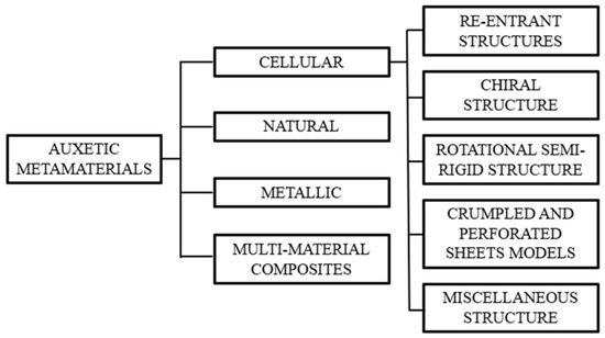
Figure 2.
General classification of auxetic materials [18].
On the other hand, when the classification given in Figure 2 is considered, the models under investigation fall into the category of cellular auxetic structures and approximate the basic form of the Reentrant design structure. But the characteristic that sets them apart from the Reentrant structure comes from looking at hexagons with varying arm angles according to the Reentrant design [8]. The condition resulting from variations in the arm radii is explored instead of changes in the arm angles, because the models under examination were created by combining radial joints.
2. Aim and Motivation of the Study
The aim of the present study is to investigate the overall structural behavior of a well-known Reentrant auxetic design geometry under static, impulsive, and harmonic loading conditions and to develop alternative structures with comparable or enhanced energy absorption capacity through design modifications. There are numerous studies that test alternative geometries to evaluate auxetic design structures in various application areas. The auxetic structure design obtained by placing a chiral geometry within a hexagon and connecting the tangent joints of the central ring to the hexagon’s diagonals was investigated by Bian et al. [19]. One of the alternative design studies within the Reentrant family, known as the Arrow Head configuration, incorporates repeating triangular patterns. The behavior of this structure, which can be realized in two or three dimensions under mechanical impact loading, has also been examined [20,21].
Adjustable parameters in the Reentrant design include the cell length, the connection--arm angles, and the wall thickness of the members. However, the Reentrant geometry inherently exhibits limited deformation under load, regardless of the raw material. Therefore, to achieve high strength under large deformation inputs, Reentrant structures must be multilayered. As the number of layers increases, they remain functional at higher displacement levels and, consequently, can absorb more energy [22]. To overcome this limitation of the Reentrant geometry and improve the stress distribution under load, an S-shaped geometric design was evaluated; examinations of specimens machined from 316L stainless steel show that this configuration distributes the load and prevents premature collapse [23]. Unlike auxetic structures formed by connecting joints in specific configurations, the mechanical strength behavior and Poisson’s ratio under load can also be modified by hollowing out selected areas of a solid surface [24,25]. The high energy absorption capacity of auxetic structures thus presents opportunities for their use as damping elements. Furthermore, design structures classified within the so-called rotational semi-rigid group which deform under load through localized thinning at specific joint regions can, for example, be applied in a jumping robot [26].
Within the scope of the present study, the responses of two types of auxetic structures to static, impulsive, and harmonic load inputs were examined. Using the well-known Reentrant structure as a reference, Arched-Reentrant design concepts were examined as potential substitutes. The structural response of the Reentrant structures at different arm angles were evaluated, and, when radial joints were employed, the use of joints of various diameters was assessed. Alternative models based on the Arched-Reentrant concept were then developed to identify those yielding the most successful outputs, and their advantages over the Reentrant model were elucidated. Design analyses were carried out using ANSYS-2025-R1 software, and test specimens were fabricated from TPU95A filaments of Porima3D by using a 3D printer of Creality Ender 3 S1 Pro from authorized distributor in Turkey.
In this study following analyses were conducted.
- Compression Test Under Static Load
- The deformation behavior of the specimens was examined.
- The reaction forces generated by the specimens during the compression process and their energy absorption capacities were investigated.
- Impulse Load Test
- The damping behaviors of the specimens under impulse load were examined.
- Harmonic Load Test
- The first natural frequencies of the test specimens across the specified frequency spectrum were examined using harmonic analysis. At the resonance frequencies, the reaction forces and displacements generated by the structures were compared.
3. Materials and Method
3.1. Materials Information
TPU raw material is utilized in numerous applications thanks to advances in chemical-industry technologies, and it has also been featured in various recently published articles on mechanical strength.
Part production from TPU raw material is also enabled by layered manufacturing technologies, which have been the focus of the most recent studies. Xu et al. produced specimens via Selective Laser Sintering (SLS) technology and conducted various mechanical tests to evaluate the mechanical performance of the TPU specimens manufactured by this method [27].
Another and the most widely known layered manufacturing method, Fused Deposition Modeling (FDM) technology, also enables part fabrication using TPU raw material. In this context, Haid et al. produced specimens from TPU95A filaments via the FDM method and subjected them to various mechanical strength tests [28].
In auxetic structural design studies, a variety of materials such as TPU, thermoplastic elastomer (TPE), polylactic acid (PLA), and acrylonitrile butadiene styrene (ABS) can be considered depending on the specific objectives of the study. In the scope of the present study, specimens with a shore hardness of 95A of TPU were employed.
The required raw material properties of TPU95A, including the material density, tensile modulus, Poissons’s ratio, experimental viscoelastic tension, and compression data, were extracted from the findings of the study by Haid et al. [28] in order to generate a material model in ANSYS-2025-R1 for the finite element analysis. The Creality Ender3 S1 Pro model 3D printer (Figure 3a) was used to produce the specimens.
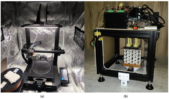
Figure 3.
Devices. (a) Three-dimensional printer for specimen manufacturing. (b) Compression test device.
The printing settings, including the bed and nozzle temperatures, remained consistent with Haid et al.’s work [28]. Using a standard 0.4 mm nozzle diameter and 25 mm/s printing speed, a minimum layer height was chosen. To maintain a consistent level of production quality, the filaments were dried in a 40 °C environment for two hours prior to printing. Due to the lack of an exterior cover, this 3D printer was covered with an additional one during the printing process to maintain a steady temperature. To test the manufactured specimens’ deformation capacity, the compression test device, produced within the scope of this study (Figure 3b), was used. The test device compresses the specimens via a linear motion system driven by a Nema 17 stepper motor of Changzhou Chuangwei from China, controlled with an Arduino Mega of Arduino from Italy and stepper driver TB6600 of JSS from China. With the help of the stepper motor, it is possible to observe the deformation of specimens according to the applied displacement accurately.
The damping characterization of the specimens was carried out using Rayleigh damping coefficients. Taking into account the first natural frequencies of all specimens, the mass proportional damping coefficient was set to 1.8787 and the stiffness proportional damping coefficient to 0.0001586, so as to achieve a damping ratio of 0.15 over the 1 Hz to 300 Hz range. This frequency range was selected to cover the first natural frequency of all specimens. Test findings from a related study utilizing 3D-printed specimens made from the same raw material were used as a reference for the damping ratio of the TPU95A material [29]. The TPU raw material is classified by a constant known as the Shore hardness value and can be produced across a very wide spectrum, as shown in Figure 4.

Figure 4.
Hardness range of different elastomers [30].
3.2. Analysis Methods
In the present study, three different analyses were conducted to compare five distinct models. The first analysis performed was the compression test under static load. Within the scope of the study, a common compression test value of 30mm was selected for all models in order to enable consistent comparison. In order to guarantee that the analysis was carried out up to the point where symmetry was maintained across all samples until geometric distortion, this value was established based on the specimen that showed the longest continuance of symmetric deformation during compression. Work defined with the specific energy absorbed (SEA) formula has been determined by measuring the specimen’s axial displacement and the ground reaction force value in order to assess the absorbed energy [1].
The second analysis performed was the impulse load test analysis. In this test, over a 0.25 s period, the ground reaction forces produced by a 20 N load applied to all specimens within 0.001 s were examined. This analysis assessed how quickly each specimen could return to the initial state following the load input. The specimens were then compared using the ground reaction force and maximum axial displacement. Furthermore, the root mean square (RMS) values of the displacements and reaction forces obtained for impulsive input have been examined.
The third analysis performed was the harmonic load test analysis. In this test, a 1 N load was applied along the vertical axis over a frequency range from 1 Hz to 300 Hz, and the first natural frequencies related to the in-plane modes of all models, as well as the reaction forces and axial displacements generated at their resonance frequencies, were examined.
In all analyses, the effect of the input (displacement and force) along the Y axis was investigated. Figure 5 shows the finite element model and the boundary conditions of the analysis model. As can be seen from the Figure 5, the bold red arrows symbolize the applied force, and the inclined red lines at the bottom of the parts show the fixed surfaces. In the static, impulse, and harmonic analyses, all the inputs and fixed surfaces are defined for the same region of all specimens. In the analyses tet10, hex20, and wedge15, mesh elements have been used, according to necessity, with the number of nodes over 50,000 at an average of 25,000 elements and the mesh metrics of element quality kept at 0.6, on average over 1. To ensure mesh independence, a node count over 80,000 was employed, and the displacement shown in Figure 5 along the X-axis was analyzed to see the convergence, as shown in Figure 6. The contact definitions were made as self-contact or body contact, which detects whether the part walls interfere with each other. In Figure 5, and represent the transverse displacement, and shows the axial displacement. The ground reaction forces are taken from the fixed surfaces of the specimen in the finite element analysis model.
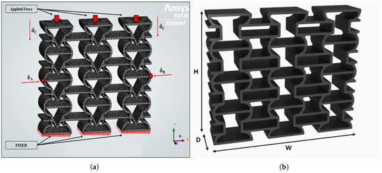
Figure 5.
Finite element analysis definitions and dimensions. (a) The finite element model of a sample specimen. (b) Specimen dimensions.
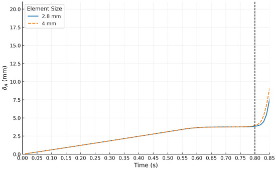
Figure 6.
Comparison of the deformation for different mesh sizes.
Different element numbers were used to analyze the effect of the mesh size on the numerical results, and no considerable difference was observed, as seen in Figure 6. The vertical line represents the starting of unsymmetrical deformation, which is not considered within the scope of the study.
4. Results and Discussion
Within the scope of this study, the test results of the Arched-Reentrant structures proposed as alternatives based on the Reentrant design were evaluated under identical analysis conditions. The specimen definitions were made as shown in Figure 7. For the specimens examined in terms of vibration isolation and energy-absorption capacity, the models analyzed as counterparts to the Reentrant structure are shown in Figure 8.
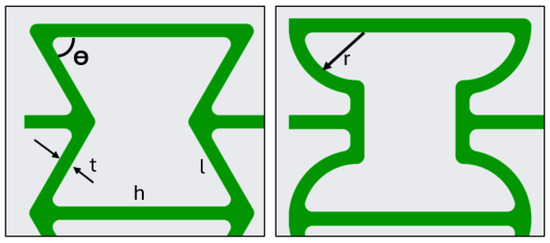
Figure 7.
Dimensional parameters of the Reentrant and Arched-Reentrant structures.
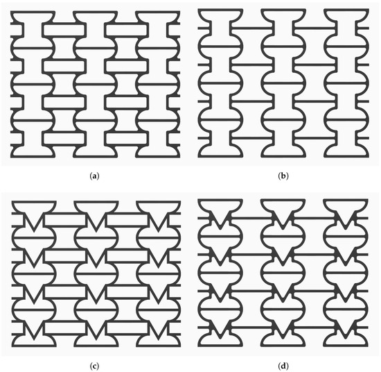
Figure 8.
Proposed auxetic designs. (a) Arched-Reentrant. (b) Arched-Reentrant-V1. (c) Arched-Reentrant-V2. (d) Arched-Reentrant-V3.
The Reentrant design structure was examined with three different arm angles, = 40°, 50°, and 60°. In the Arched-Reentrant structures, the primary design variable was the limb radius (r), taken as 4, 6, and 8 mm. The width, length, and height of all specimens were held constant and not varied as design parameters. Specifically, each specimen had a width (W) of 118 mm, a height (H) of 102 mm, and a depth (D) of 25 mm, with a wall thickness (t) of 1.8 mm. The base arm length (h) to variable angled arm length (l) ratio was kept at roughly 0.5 in all Reentrant designs. This h/l ratio is reported as a design parameter in various studies [7,22]. Lastly, the impacts of changing the Arched-Reentrant limb radius (r) and the Reentrant arm angle (), which are the only design parameters, were examined.
In the analyses, as the specimen masses varied with the design modifications, to isolate the direct effect of those modifications, the results were normalized by each specimen’s masses listed in Table 1.

Table 1.
Mass values of the specimens.
4.1. Analysis Results of the Compression Test Under Static Load
To assess the energy absorption capacities of the specimens, all specimens were compressed by 30 mm, and the resulting ground reaction forces as a function of displacement were examined, as shown in Figure 9. In this figure, the blue shaded region labeled A (blue-shaded area) shows that the auxetic form is preserved, and the specimen deforms symmetrically; however, after the maximum strength point, the response enters region B (green-shaded area), where asymmetric collapse occurs, and the auxetic structure fails. The area under this curve represents the energy absorbed by the specimens throughout the compression process. Figure 10, Figure 11 and Figure 12 provide a comparative representation of the energy uptake by the specimens in their auxetic state up to the deformation region indicated with black dots. In similar studies, the energy storage capacities of Reentrant structures as a function of arm angle have also been investigated [22].
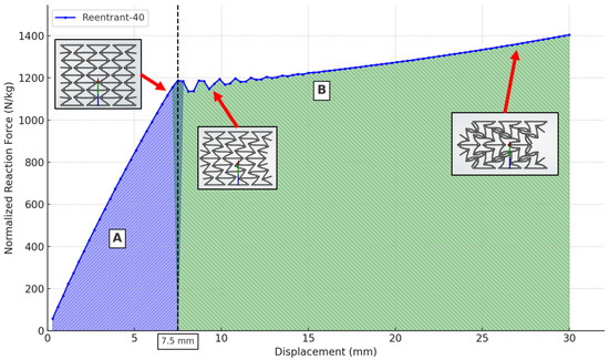
Figure 9.
Displacement dependent absorbed energy under static load.
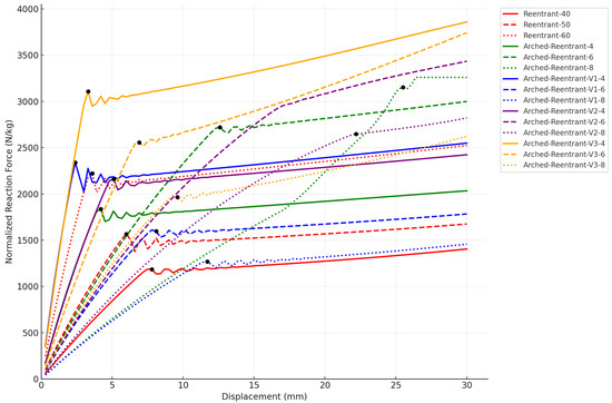
Figure 10.
Displacement dependent reaction forces of the examined specimens.
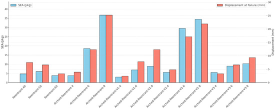
Figure 11.
Energy absorbed during auxetic deformation.
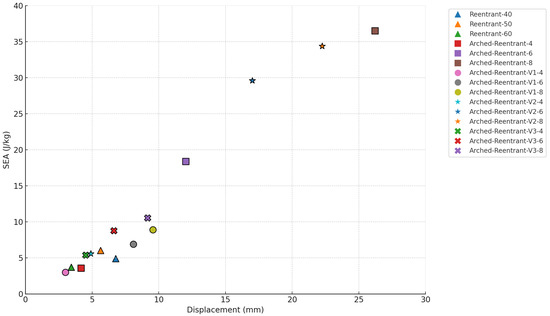
Figure 12.
SEA-displacement cluster analysis.
Based on the results obtained from the static analysis, the following observations can be made:
- Reentrant structures subjected to static loading demonstrate increasingly rapid response over small displacement intervals as the arm angle increases.
- As the arm angles of Reentrant structures increase, their stiffness rises, causing them to attain higher energy absorption within shorter displacement ranges. However, in the auxetic state, the total energy absorbed does not depend on the arm angle. When examining the Reentrant 40°, 50°, and 60° specimens in Figure 11 and Figure 12, the SEA results are close to each other. The varying arm angle only determines the displacement level at which a given amount of energy is reached.
- Arched-Reentrant-8 is the configuration that achieves the maximum energy absorption while maintaining its auxetic form. In the Arched-Reentrant design, the amount of absorbed energy varies in proportion to changes in the limb radius. Accordingly, increasing the limb radius leads to higher energy storage levels, and with a larger radius, the structure can absorb energy over longer displacement ranges.
- Arched-Reentrant-6-8 and Arched-Reentrant-V2-6-8 have the most distinct results compared to other specimens, as can be seen in Figure 12. An auxetic structure must be deformation-resistant in order to maintain its ability to absorb energy under load. Because of the nature of auxetic structures, cellular designs with greater rigidity along the transverse axis have a higher capacity for energy storage and are less prone to experience asymmetric deformation.
Figure 13 shows the Reentrant-60 specimen’s deformation pattern during compression, which started before a 5 mm displacement and was consistent with the computational study. Following geometric distortion, the structure was no longer able to generate greater reaction force. Figure 14 illustrates how the Arched-Reentrant-8 specimen underwent symmetrical deformation up to about 20 mm during the compression test. However, the model’s form was disturbed after its internal collapse capability was surpassed. The level of deformation and the manner in which the specimens deformed are similar between the findings of the compression experiment and the static analysis, confirming the printing parameters of the specimens and the material parameters utilized in the finite element analysis. In order to verify the precision of the experimental test findings, the specimens underwent three compression tests, and the displacement at which the unsymmetrical deformation started was examined.
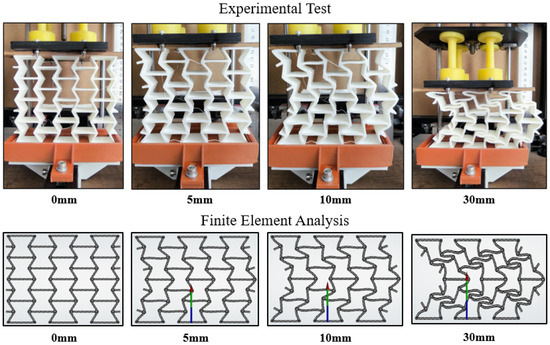
Figure 13.
Behavior of the Reentrant-60 model during compression.
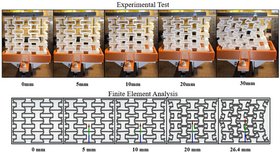
Figure 14.
Behavior of the Arched-Reentrant-8 model during compression.
The deformation of the specimens varies according to the design features, as shown in Figure 13 and Figure 14. The Reentrant design structure features a repeating cellular structure and integrates arms positioned at particular angles. In Reentrant structures, the load-bearing capacity perpendicular to the direction of the compression force diminishes as the arm angle () increases, whereas the stress in the arms carrying the load in the direction of the compression force increases. The structure rapidly approaches its maximum reaction force and loses its structural symmetry as the arm angle increases because it becomes less resistive in the direction perpendicular to the force. The impact of arm angle modification on force bearing capacity in Reentrant structures is shown in Figure 10.
Cells with Arched-Reentrant designs are made up of arc-shaped limbs. In order to equally resist reaction forces perpendicular to and in the direction of the force, these limbs are oriented toward the center of the structure. Under load, structures must bend symmetrically to preserve structural integrity while storing energy. Because of their arc structure instead of constant arm angle, Arched-Reentrant structures are able to better preserve their structural integrity perpendicular to the force, allowing them to store more energy during auxetic deformation than Reentrant structures.
The Poisson’s ratio is fundamentally defined as the ratio of the dimensional change along the horizontal axis to that along the vertical axis, as given in Equations (1)–(3) and represented in Figure 15. Figure 16 illustrates the variation in the Poisson’s ratios with respect to displacement for the models analyzed in the computational environment.
where x stands for transverse strain, and y stands for axial strain.
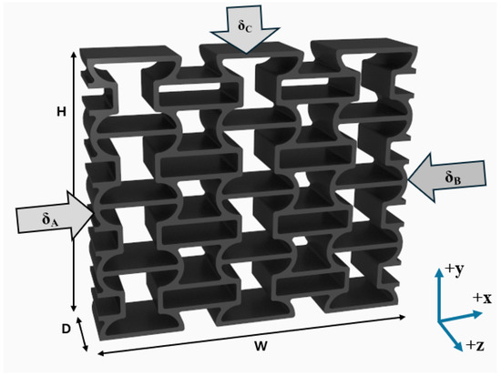
Figure 15.
Poisson’s ratio definitions and dimensions.
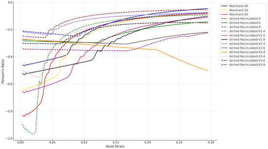
Figure 16.
Variation in Poisson’s ratio during compression.
The fundamental characteristic of auxetic structures is that, during compression, as the specimens undergo displacement along the vertical axis y, their side walls collapse inward, producing negative Poisson’s ratios.
Figure 16 presents the variation in the Poisson’s ratio calculated from numerical compression analyses, and the highest ratio is obtained for the Arched-Reentrant-V1-4 model. In the known Reentrant design model, the Poisson’s ratio, which is maximal at the onset of loading, tends directly toward the positive axis. The Arched-Reentrant design models exhibit different behaviors. In particular, the V1-4 and V3-4 configurations exhibit a sharper loss of form upon reaching the maximum load, while the Poisson’s ratio rapidly decreases as it moves away from the positive axis toward more negative values. Structures with Poisson’s ratios that initially deviate from the positive axis more quickly under compressive loads also recover to initial conditions in the impulse input analysis more quickly. In the harmonic studies, they also show the smallest displacement changes and reaction force magnitudes.
The Poisson’s ratio diverging from the positive axis offers an indication of structural resilience or energy-absorption capacity; however, rather than the ratio’s absolute value, it is more appropriate when interpreting structural stiffness to examine whether the Poisson’s ratio can be maintained or further decreased toward more negative values as the specimen deforms under load, thereby providing a more accurate assessment of structural rigidity or energy absorbing capacity.
4.2. Impulse Load Test Results
The vibration damping capabilities of the structures were compared in the impulse-input test by evaluating how rapidly they returned to the initial state following the impulse load. The comparisons were made by using the RMS values of the normalized reaction forces. The variations in the Reentrant models reaction forces and displacements, associated with different arm angles under the impulse loading, are presented in Figure 17 and Figure 18.
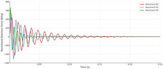
Figure 17.
Effect of arm angle on the reaction force in Reentrant structures under impulse loading.
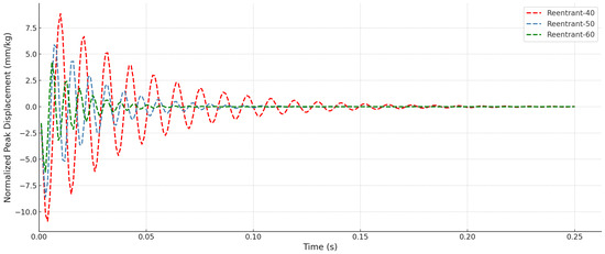
Figure 18.
Effect of arm angle on the displacement in Reentrant structures under impulse loading.
Fundamentally, it is found that the specimen stiffness increases with the increase in the Reentrant arm angle, leading to higher initial response forces and less total displacement. As a result, the damping rate builds up with the increasing arm angle. To facilitate comparison, the raw data were post-processed by computing the RMS values, which are shown in Figure 19. Figure 19 shows the RMS values of reaction forces and displacements of all specimens. In this context, the original Arched-Reentrant design model does not outperform the Reentrant model in the dynamic tests as it does in the static tests. However, when other variants of the same Arched-Reentrant concept are examined, it is evident that under dynamic loading the Arched-Reentrant V2 and V3 specimens with their differing limb diameters demonstrate superior performance relative to the Reentrant models. Overall, when the impulse response is taken into consideration, the required returning time to the initial state of the Reentrant structures decreases as their arm angles increase (40->50->60), while the required returning time to the initial state of the Arched-Reentrant structures decreases as the limb radius decreases (8->6->4).
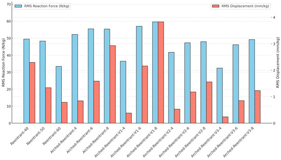
Figure 19.
RMS values of reaction force and displacements for all models under impulse input.
4.3. Harmonic Analysis Test Results
In systems subjected to dynamic loading, the operating frequencies of machine elements and their natural frequencies play a vital role in the generation of undesirable forces during operation. The structures evaluated as damping elements have been compared in terms of their resonance frequencies within the specified frequency spectrum and criteria such as the peak magnitudes at resonance and the bandwidth of the response curve. Figure 20 illustrates how the first natural frequencies of the Reentrant and Arched-Reentrant design structures vary among the various designs.
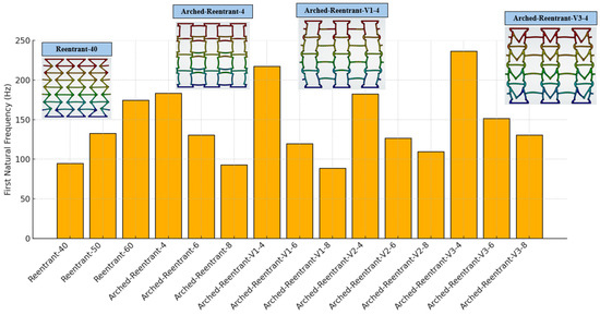
Figure 20.
The first natural frequencies and sample mode shapes of the specimens.
As the design parameters change, the first natural frequency changes for every design. For the Reentrant structures, the stiffness rises linearly with the increasing arm angle. Conversely, in the Arched-Reentrant structures, an increase in limb radius leads to reduced rigidity, and consequently, their first natural frequencies decrease.
The variations in the ground reaction force and peak displacement values for the Reentrant design structures obtained from harmonic analyses at varying arm angles are presented in Figure 21. As the structural stiffness increases (i.e., as the Reentrant arm angle increases), both the reaction forces and displacements decrease. Furthermore, the figure shows that the displacement change is greater than the change in the reaction force.
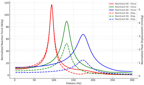
Figure 21.
Reaction force and displacement responses of the Reentrant auxetic design in harmonic analysis.
To evaluate the effect of the design modifications, the system responses of all specimens at their first natural frequencies were examined using the half-power method, and the resulting damping ratios of the structures are presented in Figure 22.
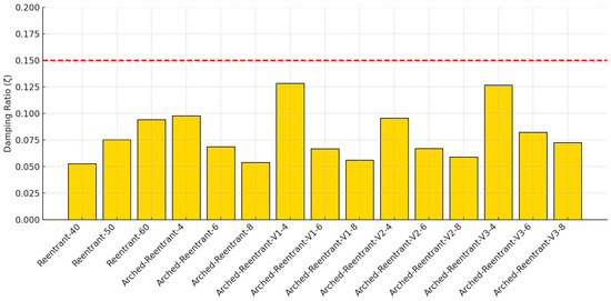
Figure 22.
Variation in the damping ratios calculated using the half-power method.
When Reentrant and Arched-Reentrant structures are compared, the Arched-Reentrant designs generally exhibit damping levels comparable to those of the Reentrant structures; however, the variation in the damping ratios of the Arched-Reentrant models as a function of limb radius is not linear as in the Reentrant models. It is also observed that the Arched-Reentrant specimens with a 4 mm radius attain the highest damping ratios. The frequency responses of all models within the frequency range of 1–300 Hz for harmonic displacement and force loadings are given in Figure 23 and Figure 24. Using the half-power approach on the first natural frequency of specimens on the reaction force over frequency graphs, as shown in Figure 23, the damping ratios have been determined.
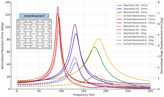
Figure 23.
Reaction force and displacement results of the Reentrant–Arched-Reentrant auxetic design in harmonic analysis.
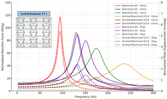
Figure 24.
Reaction force and displacement results of the Reentrant–Arched-Reentrant-V3 auxetic design in harmonic analysis.
When examining the results comparing the Reentrant, Arched-Reentrant, and Arched-Reentrant-V3 models, it can be seen in Figure 23 that the Reentrant model and the Arched-Reentrant models converge to similar results. In the design study aimed at achieving higher damping capability, the Arched-Reentrant-V3 model stands out, as evident in Figure 24. In particular, for the Arched-Reentrant V3-4 model, the displacement values at the resonance frequency remain considerably lower than those of the Reentrant-60 model, and the resonance bandwidth is broader.
The peak reaction force and displacement values obtained from the harmonic analyses of all specimens are presented in Figure 25. It can be concluded that the Arched-Reentrant-V3 models offer better damping than the Reentrant models because of their lower displacement, higher resonance frequency, and lower reaction force when measured in terms of the peak displacement and reaction-force values at the resonance frequency shown in the bar charts.
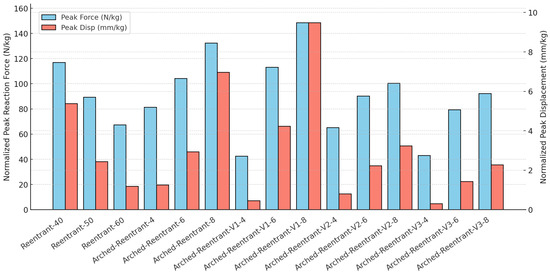
Figure 25.
Harmonic analysis peak results for all specimens at first natural frequency.
5. Conclusions
The current study suggests several variations of a novel design model that can generate better responses than those of the original configuration under both static and dynamic loads. This is performed in order to develop alternative designs based on the well-known Reentrant structural model, which has been the subject of a lot of auxetic design research with radial arm geometries.
The numerical static and dynamic analyses yielded the following findings summarized belows:
- Under static loading, Arched-Reentrant structures respond in parallel to variations in the design parameter and store more energy while deforming symmetrically. The Arched-Reentrant design stands out with its maximum energy storage capacity during symmetric deformation, compared to the known Reentrant model.
- The Arched-Reentrant-V3 design structure, in all of its variations, shows 50% lower displacement values under dynamic loading than those obtained for Reentrant design models.
- The higher first natural frequency, higher damping ratios, lower peak reaction force, and displacement values of the Arched-Reentrant-V3 models make them suitable for application in dynamic system designs.
- The Arched-Reentrant structures developed within the scope of the study can be used as energy absorbing structural components in applications requiring vibration isolation such as engine blocks or compressors. Future research is intended to focus on experimental studies of energy dissipation based on the design of structural elements with Arched-Reentrant configuration.
Author Contributions
Methodology, S.S.; Software, S.S.; Validation S.S.; Resources, S.S. and Z.K.; Writing—original draft preparation S.S.; Writing—review and editing Z.K.; Supervision Z.K. All authors have read and agreed to the published version of the manuscript.
Funding
This research received no external funding.
Institutional Review Board Statement
Not applicable.
Informed Consent Statement
Not applicable.
Data Availability Statement
The data presented in this study are available on request from the corresponding author.
Conflicts of Interest
The authors declare no conflicts of interest.
References
- Günaydın, K.; Rea, C.; Kazancı, Z. Energy absorption enhancement of additively manufactured hexagonal and re-entrant (auxetic) lattice structures by using multi-material reinforcements. Addit. Manuf. 2022, 59, 103076. [Google Scholar]
- Zhi, Q.; Li, D.; Sun, H.; Zhu, W. Adjustment of multi-directional elastic properties of chiral metamaterial via a 3D printing-based soft-hard bi-material strategy. Compos. Struct. 2023, 307, 116646. [Google Scholar] [CrossRef]
- Çakan, B.G.; Ensarioğlu, C.; Küçükakarsu, V.M.; Tekin, İ.E.; Çakır, M.C. Experimental and numerical investigation of in-plane and out-of-plane impact behaviour of auxetic honeycomb boxes produced by material extrusion. J. Fac. Eng. Archit. Gazi Univ. 2021, 36, 1657–1667. [Google Scholar]
- Raeisi, S.; Tapkir, P.; Ansari, F.; Tovar, A. Design of a Hybrid Honeycomb Unit Cell with Enhanced In-Plane Mechanical Properties; SAE Techical Paper; SAE International: Warrendale, PA, USA, 2019. [Google Scholar]
- Hou, S.; Li, T.; Jia, Z.; Wang, L. Mechanical properties of sandwich composites with 3d-printed auxetic and non-auxetic lattice cores under low velocity impact. Mater. Des. 2018, 160, 1305–1321. [Google Scholar] [CrossRef]
- Duc, N.D.; Eock, K.S.; Tuan, N.D.; Tran, P. New approach to study nonlinear dynamic response and vibration of sandwich composite cylindrical panels with auxetic honeycomb core layer. Aerosp. Sciend Technol. 2017, 70, 396–404. [Google Scholar] [CrossRef]
- Cong, P.H.; Khanh, N.D.; Khoa, N.D.; Duc, N.D. New approach to investigate nonlinear dynamic response of sandwich auxetic double curves shallow shells using TSDT. Compos. Struct. 2018, 185, 455–465. [Google Scholar] [CrossRef]
- Critchley, R.; Hazael, R.; Bhatti, K.; Wood, D.; Peare, A.; Johnson, S.; Temple, T. Blast mitigation using polymeric 3D printer auxetic re-entrant honeycomb structure: A preliminary study. Int. J. Prot. Struct. 2022, 13, 469–486. [Google Scholar] [CrossRef]
- Ebrahami, M.S.; Noruzi, M.; Hamzehei, R.; Etemadi, E.; Hashemi, R. Revolutionary auxetic intravascular medical stents for angioplasty applications. Mater. Des. 2023, 235, 112393. [Google Scholar] [CrossRef]
- Jiang, Y.; Shi, K.; Zhou, L.; He, M.; Zhu, C.; Wang, J.; Li, Y.; Sun, D.; Feng, G.; Yi, Y.; et al. 3D-printed auxetic-structured intervertebral disc implant for potential treatment of lumbar herniated disc. Bioact. Mater. 2023, 20, 528–538. [Google Scholar] [CrossRef]
- Guan, Y.; Zhang, X.; Cao, X.; Yang, H.; Wang, S.; Cao, W.; He, C. Dual-material TPMS metamaterial with high load-bearing capacity and performance stability. Int. J. Mech. Sci. 2025, 303. [Google Scholar] [CrossRef]
- Jiang, D.; Thissen, H.; Hughes, T.C.; Yang, K.; Wilson, R.; Murphy, A.B.; Nguyen, V. Advances in additive manufacturing of auxetic structures for biomedical applications. Mater. Today Commun. 2024, 40, 110045. [Google Scholar] [CrossRef]
- Yang, H.; Yang, F.; Cao, X.; Guan, Y.; Zheng, X.; Qin, F.; Zhang, Z.; Wang, S.; Zhang, Y. Quai-static compression and three-point bending behavior of the dual-material gyroid material. Thin-Walled Struct. 2025, 216, 113600. [Google Scholar] [CrossRef]
- Lvov, V.A.; Senatov, F.S.; Korsunsky, A.M.; Salimon, A.I. Design and Mechanical Properties of 3D-Printed Auxetic Honeycomb Structure. Mater. Today Commun. 2020, 24, 101173. [Google Scholar] [CrossRef]
- Mazur, V.V.; Rykov, S.P. The Ability of Airless Tires to Self-Purify. IOP Conf. Ser. Earth Environ. Sci. 2021, 666, 042012. [Google Scholar] [CrossRef]
- Sardinha, M.; Reis, L.; Ramos, T.; Vaz, M.F. Non-pneumatic tire designs suitable for fused filament fabrication: An overview. Procedia Struct. Integr. 2022, 42, 1098–1105. [Google Scholar] [CrossRef]
- Kim, K.; Kim, D. Contact Pressure of Non-Pneumatic Tires with Auxetic Honeycomb Spoke. Soc. Aerosp. Syst. Eng. 2010, 4, 1–9. [Google Scholar]
- Kelkar, P.U.; Kim, H.S.; Cho, K.H.; Kwak, J.Y.; Kang, C.Y.; Song, H.C. Cellular Auxetic Structures for Mechanical Metamaterials: A Review. Sensors 2020, 20, 3132. [Google Scholar] [CrossRef]
- Bian, Z.; Gong, Y.; Sun, Z.; Zhao, L.; Zhang, J.; Hu, N. Design and energy absorption characteristics of a novel honeycomb with embedded chiral structures. Compos. Struct. 2024, 333, 117944. [Google Scholar] [CrossRef]
- Gao, Q.; Ge, C.; Zhuang, W.; Wang, L.; Ma, Z. Crashworthiness analysis of double-arrowed auxetic structure under axial impact loading. Mater. Des. 2019, 161, 22–34. [Google Scholar] [CrossRef]
- Wang, Y.; Wang, L.; Ma, Z.D.; Wang, T. A negative Poisson’s ratio suspension jounce bumper. Mater. Des. 2016, 103, 90–99. [Google Scholar] [CrossRef]
- Kamthe, A.; Walame, M.V. Determination of Energy Absorption Capacity of Auxetic Hexagon Structure with Different Geometrical Parameters by Simulation and Experimentation. Int. Res. J. Eng. Technol. 2021, 8, 3500–3503. [Google Scholar]
- Meena, K.; Singamneni, S. A new auxetic structure with significantly reduced stress concentration effects. Mater. Des. 2019, 173, 107779. [Google Scholar] [CrossRef]
- Harinarayana, V.; Shin, Y.C. Design and evaluation of threeedimensional axisymmetric mechanical metamaterial exhibiting negative Poisson’s ratio. J. Mater. Res. Technol. 2022, 19, 1390–1406. [Google Scholar] [CrossRef]
- Wang, H.; Xiao, S.; Wang, J. Disordered auxetic metamaterials architected by random peanut-shaped perturbations. Mater. Des. 2021, 212, 110291. [Google Scholar] [CrossRef]
- Lee, Y.J.; Misra, S.; Chen, W.H.; Koditschek, D.E.; Sung, C.; Yang, S. Tendon-Driven Auxetic Tubular Springs for Resilient Hopping Robots. Adv. Intell. Syst. 2022, 4, 2100152. [Google Scholar] [CrossRef]
- Xu, T.; Shen, W.; Lin, X.; Xie, Y.M. Mechanical Properties of Additively Manufactured Thermoplastic Polyurethane (TPU) Material Affected by Various Processing Parameters. Polymers 2020, 12, 3010. [Google Scholar] [CrossRef]
- Haid, D.M.; Duncan, O.; Hart, J.; Foster, L. Characterisation of thermoplastic polyurethane (TPU) for additive manufacturing. In Proceedings of the 14th Symposium of the Section Sport Informatics and Engineering of the German Society of Sport Science, Chemnitz University of Technology, Chemnitz, Germany, 29–30 September 2022; Volume 85, pp. 85–88. [Google Scholar]
- Zu, R.; Chen, W.; Huang, Y.; Chen, Y.; Du, C.; Fan, Q.; Li, H.; Liu, H. Tailor-made 3D printing TPU/PLA composites for damping and energy absorption. Mater. Des. 2025, 252, 113752. [Google Scholar] [CrossRef]
- Chynybekova, K.; Choi, S.M. Flexible Patterns for Soft 3D Printed Fabrications. Symmetry 2019, 11, 1398. [Google Scholar] [CrossRef]
Disclaimer/Publisher’s Note: The statements, opinions and data contained in all publications are solely those of the individual author(s) and contributor(s) and not of MDPI and/or the editor(s). MDPI and/or the editor(s) disclaim responsibility for any injury to people or property resulting from any ideas, methods, instructions or products referred to in the content. |
© 2025 by the authors. Licensee MDPI, Basel, Switzerland. This article is an open access article distributed under the terms and conditions of the Creative Commons Attribution (CC BY) license (https://creativecommons.org/licenses/by/4.0/).