Article

Real-Time Monitoring of 3D Printing Process by Endoscopic Vision System Integrated in Printer Head

by
Martin Kondrat
,
Anastasiia Nazim
*,
Kamil Zidek
,
Jan Pitel
,
Peter Lazorík
and
Michal Duhancik
Faculty of Manufacturing Technologies Based in Prešov, Technical University of Košice, Bayerova 1, 080 01 Prešov, Slovakia
*
Author to whom correspondence should be addressed.
Appl. Sci. 2025, 15(17), 9286; https://doi.org/10.3390/app15179286
Submission received: 30 June 2025 / Revised: 3 August 2025 / Accepted: 21 August 2025 / Published: 24 August 2025
(This article belongs to the Special Issue Real-Time Detection in Additive Manufacturing)

Abstract

This study investigates the real-time monitoring of 3D printing using an endoscopic camera system integrated directly into the print head. The embedded endoscope enables continuous observation of the area surrounding the extruder, facilitating real-time inspection of the currently printed layers. A convolutional neural network (CNN) is employed to analyse captured images in the direction of print progression, enabling the detection of common defects such as stringing, layer shifting, and inadequate first-layer adhesion. The primary innovation of this work lies in its capacity for online quality assessment and immediate classification of print integrity within predefined thresholds. This system allows for the prompt termination of printing in the case of critical faults or dynamic adjustment of printing parameters in response to minor anomalies. The proposed solution offers a novel pathway for optimising additive manufacturing through real-time feedback on layer formation.

1. Introduction

As 3D printing becomes a critical technology across industry, healthcare, and research, challenges related to quality control and process stability persist. This study investigates the application of advanced technologies—such as image analysis and machine learning—for real-time detection of printing defects, which has the potential to enhance both production efficiency and product quality. Its overarching aim is to contribute to the optimisation of 3D printing in industrial contexts by improving automation and reliability monitoring.
The field of 3D printing is more diverse than it might initially appear. It has found significant applications in sectors such as construction and automotive manufacturing. The most well-known technique associated with 3D printing involves the use of filament that is heated and extruded through a nozzle to build the desired shape on a print platform via a layer-by-layer process. The term “3D printing” encompasses several distinct methods, each utilising different machines and materials. This technology allows for the fabrication of a wide array of objects—from simple flowerpots to rocket engines. While the manufacturing techniques vary considerably, all fall under the umbrella of additive manufacturing. Substantial progress has been made in improving the quality and performance of printed components, particularly through ongoing advancements in Fused Deposition Modelling (FDM), the most widely used technique in 3D printing [1]. As industries transition into the era of the Fourth Industrial Revolution, the integration of intelligent manufacturing systems has highlighted the pivotal role of additive manufacturing in enhancing efficiency, reducing waste, and enabling rapid prototyping. This technology not only facilitates the production of complex geometries but also promotes sustainability through its economic and environmental benefits [2].
Consequently, assessing the quality of 3D printing requires consideration of both its technical capabilities and its broader implications for future manufacturing paradigms [3]. In healthcare, for example, 3D printing is employed to produce personalised implants and prostheses, enabling bespoke solutions that improve clinical outcomes. The ability to fabricate patient-specific surgical guides, anatomical models, and implants underscores this technology’s potential to enhance surgical precision and efficiency. A review of 227 surgical cases revealed significant reductions in operative time and overall improvements in medical outcomes [4]. Similarly, the aerospace industry benefits from weight reduction and increased component functionality, which together contribute to improved fuel efficiency and performance [5]. Enhancing the quality of 3D printed parts necessitates a holistic approach involving improvements in both design and process parameters. Key variables such as layer height, print speed, and material selection significantly affect the dimensional accuracy and mechanical strength of final products. Moreover, proper temperature control and cooling strategies can mitigate common issues such as warping and layer separation, thereby improving reliability. The integration of hybrid manufacturing techniques—combining additive and subtractive processes—has also shown promising results in terms of achieving higher precision and improved surface finishes, as supported by recent research. These combined approaches expand the applicability of 3D printing to complex geometries and intricate features that would be difficult or impossible to replicate using traditional manufacturing methods [6,7]. This integrative strategy addresses frequent challenges such as surface defects and material brittleness, illustrating how advanced 3D printing techniques can simultaneously deliver high-quality outcomes and foster innovation in manufacturing workflows [7]. However, challenges persist, especially regarding the cost-effectiveness of such innovations. Further research is required to assess whether investments in advanced 3D printing technologies will yield sustainable, long-term benefits [4]. Continued exploration into new materials—including PLA-based bio composites—is essential for enhancing performance and sustainability in sectors ranging from medical device manufacturing to automotive production. This review not only consolidates current developments but also identifies emerging trends, reinforcing the need for sustained innovation in the pursuit of superior 3D printing quality [1].

Current Research in Online Monitoring

With the continued expansion of 3D printing technology across various industries, online monitoring of the printing process has become increasingly prominent. This capability facilitates real-time supervision of production, enhancing the ability to detect and resolve errors promptly. Real-time data acquisition supports process evaluation and provides operators with immediate feedback on potential non-conformities. Such integration not only improves decision-making during production but also promotes more efficient use of resources [8]. Moreover, the adoption of cloud-based manufacturing platforms enables more flexible responses to unforeseen production challenges, ensuring that 3D printing systems maintain high levels of transparency and adaptability [3]. By leveraging these technological advancements, manufacturers can achieve greater quality assurance, significantly reducing the occurrence of defects and enhancing overall product reliability—aligned with current industry standards.
A comprehensive understanding of individual 3D printing processes has become critical for ensuring product quality, process efficiency, and system reliability. Central to these objectives is the monitoring of print parameters, which involves collecting and analysing real-time data to inform operational decisions [9,10]. Despite advancements in this field, a substantial gap remains in the standardisation of monitoring metrics. As a result, manufacturers continue to encounter inconsistencies in error rates and product quality [11,12]. Furthermore, the absence of quantitative data for many printing parameters inhibits the development of predictive models, which could otherwise enhance process control and foster innovation in manufacturing strategies.
Effective monitoring is essential, as deviations in critical parameters—such as nozzle temperature, print speed, and material feed rate—can adversely impact the quality of the printed component. These variations may lead to defects that undermine both the functionality and structural integrity of the part. Consequently, a deep understanding of the complex interactions between these parameters is vital to improving process stability and ensuring the production of high-quality components [9]. Recent studies have demonstrated the effectiveness of thermal imaging and other process measurement tools in facilitating real-time monitoring [10]. Machine learning has emerged as a promising approach for predicting outcomes based on predefined parameter sets, thereby reinforcing the link between artificial intelligence and conventional manufacturing systems [11]. This research direction is especially important given the inherently variable nature of additive manufacturing, where modifications to one parameter frequently influence others in unintended ways [13]. However, much of the existing research has focused narrowly on specific materials or technologies, often overlooking broader investigations that consider diverse materials and their properties across multiple 3D printing methods [14]. The development of monitoring protocols in additive manufacturing has evolved markedly—from early work focusing on mechanical properties to more recent efforts involving advanced, data-driven techniques. Initial studies laid the groundwork by establishing correlations between key parameters—such as print speed and layer height—and the resultant mechanical performance of the final product [9,10,11]. The contemporary literature increasingly highlights the integration of machine learning algorithms to process and analyse collected data, thereby enabling predictive maintenance and automated adjustments during printing [15]. These innovations indicate a shift towards more autonomous systems capable of learning and adapting based on historical performance data, ultimately enhancing the efficiency and resilience of additive manufacturing operations [16]. The focus has also broadened to include environmental and sustainability considerations. Recent studies have stressed the need to monitor not only print parameters but also energy consumption and material waste across various additive processes [17,18]. Collectively, these advances illustrate a progressive trajectory towards the continuous improvement of 3D printing technologies, highlighting the importance of integrating monitoring systems that support both product quality and sustainable manufacturing practices [19,20].

2. FDM Technology

Fused Deposition Modelling (FDM) has become an important technology in various industries, supporting innovation in product development and manufacturing processes. Its ability to create complex geometric shapes with high precision makes it a particularly attractive alternative in industries such as automotive and aerospace, where complex components are key to improving performance and efficiency. FDM is used, for example, for rapid prototyping, which allows engineers to quickly and efficiently modify and improve designs, significantly reducing development times. Characterised by the layered deposition of thermoplastic materials, recent innovations have expanded the applicability of FDM technology beyond simple structures to include multi-material printing, thereby expanding the possibilities for design and functional applications [21]. The parameters of 3D printing significantly influence the quality and properties of printed parts. Key parameters include layer thickness, printing speed, and the temperature and angle of application [6,22]. These parameters influence the mechanical properties, dimensional accuracy, and surface roughness of printed objects. By optimising these parameters, the mechanical properties can be improved by up to 60% [23]. Various optimisation methods, such as the Taguchi method and the Response Surface method, have been used in studies to determine the optimal parameter settings. In the case of PLA material, it was found that a low printing speed (20 mm/s), medium temperature (210 °C), and low layer height result in high dimensional accuracy and low surface roughness. Layer thickness mainly affects tensile strength, while the raster angle affects dimensional error [7]. The development of mathematical models and functional dependencies can help predict and achieve the desired properties of a part. In addition, optimising parameters such as nozzle diameter and fill level affects the mechanical properties of printed objects, influencing porosity and strength [24]. The materials used in FDM, including biodegradable plastics and composites, are consistent with sustainability goals as they reduce waste and energy consumption, as discussed in broader discussions on additive manufacturing applications. This versatility not only culminates in the production of functional parts but also highlights the ongoing development of FDM technology and its potential to meet the demands of modern manufacturing challenges in industries such as healthcare and engineering [25,26]. Advances in high-speed additive manufacturing (HSAM) illustrate the potential of FDM to become competitive with conventional techniques such as plastic injection moulding for medium-sized parts, extending its applicability beyond simple prototyping [27]. As FDM technology continues to evolve, its prospects appear increasingly promising, particularly through the integration of advanced materials and multifunctional capabilities. The introduction of 4D printing within FDM represents a paradigm shift in which printed objects can change their shape and functionality in response to stimuli from the environment [28]. In the field of materials science, the range of printable fibres is expanding, enabling the creation of stronger and more durable products that can withstand higher temperatures and stress.

2.1. FDM Print Head

The print head is a key component responsible for applying material to the print bed. Its task is to melt the filament and extrude it through a special nozzle in the exact amount and location to create the desired 3D model. It is important that it is correctly set up and maintained. Common problems such as nozzle clogging, incorrect temperature settings or faulty filament feeding can significantly affect the results of 3D printing [29]. Print heads can vary depending on the type of 3D printer but generally have several basic components (Figure 1).

2.1.1. Motors and Drives

The print head is equipped with a motor that pushes the filament through the extruder. This motor is controlled by the 3D printer’s computer and precisely controls the speed and amount of material that is extruded [29,30].

2.1.2. Extruder

A mechanism that pushes the filament through a hot block; it consists of two main parts:
  • Drive gear—toothed wheels that pull the filament into the print head.
  • Idler—a part that pushes the filament onto the drive gear to ensure smooth filament movement [29,30].

2.1.3. Hot End

A component that melts the filament; it consists of several parts:
  • Heater block—heats the hot end of the print head to the desired temperature.
  • Thermistor or temperature sensor—monitors the temperature of the heating block to maintain temperature stability.
  • Nozzle—a small opening at the end of the hot end through which the melted filament is extruded onto the print bed. The size of the nozzle affects the detail and speed of printing [29,30].

2.1.4. Cooling

Cooling is important for controlling the temperature of the print head and preventing the filament from melting prematurely. Most print heads are equipped with a fan that cools the area above the nozzle to prevent clogging or premature solidification of the filament [29,30].

2.1.5. Filament Guidance

The print head may contain a system of tubes or guides that guide the filament from the extruder to the hot end. These tubes are often made of materials that can withstand high temperatures [29,30].

3. Methodology

Errors in 3D printing often arise from multiple factors, leading to poor print quality and structural integrity. Common problems include deformation, misalignment of layers, and fibre clogging, each of which stems from different operational shortcomings. Deformation usually occurs a result of rapid temperature fluctuations, which cause uneven shrinkage of the material during cooling. Filament clogging, which often occurs as a result of insufficient material feed or impurities, stops the printing process and requires extensive troubleshooting [31]. Furthermore, the mechanical and elastic properties of printed materials can affect measurement reliability, highlighting the need for thorough monitoring throughout the printing process [32].

3.1. Mechanical Errors and Their Impact on Print Quality

In 3D printing, mechanical errors play a significant role in determining the final print quality, which directly affects the success of the production process. The complexities associated with layered construction require precise calibration and alignment; any deviation from these parameters can result in errors such as misalignment, deformation, or inconsistent layering. The occurrence of these errors not only leads to material waste—often plastic-based and non-biodegradable—but also to the structural integrity of the printed object being compromised, rendering it unsuitable for its intended use [33]. Furthermore, studies of the mechanical properties of printed materials have revealed that errors such as reduced geometric accuracy can lead to significant changes in performance under stress, especially when exposed to external forces or radiation [34].

3.2. Errors Caused by Incorrect Print Settings

With the falling prices of 3D printers, a growing community of users has emerged who use these devices for various purposes, including the production of personal components [35]. However, the spread of these inexpensive devices is accompanied by significant problems, mainly stemming from incorrect print parameter settings, which lead to errors in the final product. This problem is particularly pronounced among amateur users, where optimisation techniques are often inadequate compared to commercial manufacturers [36]. For this reason, understanding and correcting errors related to print parameters is key to improving the quality and reliability of 3D printed objects, thereby ensuring that the advantages offered by 3D printing are fully exploited [37].

3.3. Selection of Critical Errors That We Can Detect

Using online camera monitoring of 3D printing, we can check for most anomalies and defects; however, only some of them can be directly evaluated, and deformations can only be attributed to specific errors in certain cases [38]. As an example, we are not able to directly monitor the temperature of the material during printing. However, using camera recordings, we can analyse the probability of the type of deformation involved. Since unsuitable printing temperatures have distinct characteristics, if we see how the material behaves, we can assess whether it is exhibiting the deformation properties corresponding to incorrect printing temperature. For direct monitoring using cameras, we are best able to control the following variables.

3.3.1. Layer Shifting

Most printers do not have a print head movement feedback control. The printer sends a command to move to a certain position and hopes that the movement has occurred. In most cases, this works quite reliably. However, if you accidentally bump into the printer, the print head may move to a different position than expected, but it continues to print according to the original instructions, thus continuing to print in the wrong position (Figure 2a).

3.3.2. Adhesion to the Surface

It is very important that the first layer of material adheres firmly to the substrate. If the first layer does not adhere sufficiently, do not continue printing. In the best case, the product will be partially deformed, but in most cases, it will be completely unusable (Figure 2b).

3.3.3. Stringing

Stringing (Figure 2c) is one of the most common and annoying problems in 3D printing; it leads to thin, unsightly plastic strands that give the print a hairy appearance. In principle, no plastic should come out of the print nozzle unless a print is being made at that moment. However, there may be times when material ‘drips’ from the nozzle, i.e., when the solid filament is exposed to the heating element and melts in the nozzle. When the FDM printer nozzle moves from one point to another, the melted filament pulls strands behind it, which solidify and adhere to the printed parts.

4. Material and Methods

The location of the camera—whether internal (in the printer frame) or external—significantly affects the quality of monitoring and the ability to accurately capture the moment when a problem occurs.
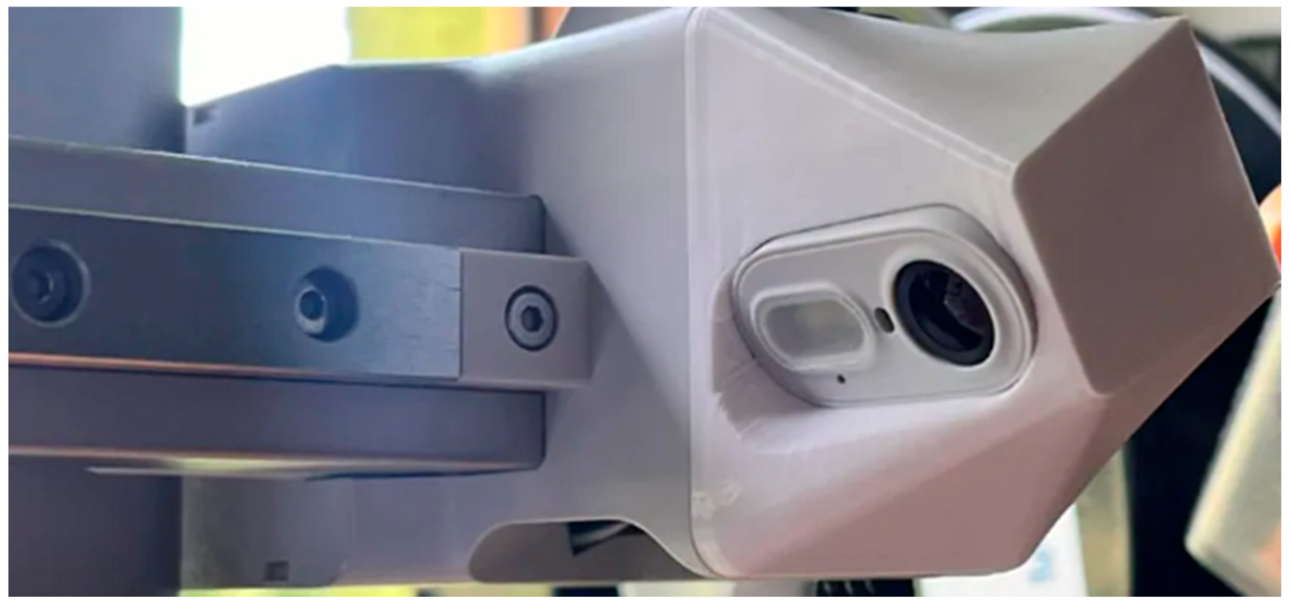
Bambu Lab printers (Figure 3) are equipped with an integrated camera directly inside the print chamber. This is a high-quality wide-angle camera (Full HD 1080p Bambu Lab, Sanghai, China) which is usually located at the front of the frame, slightly above the print bed. The camera is permanently installed and positioned so that it has a view of the entire model throughout the printing process.
These cameras are not just a passive feature; they are closely linked to Bambu Lab’s AI system, which can automatically detect problems such as warping, incomplete layers, and the print head hitting the object [40].
Figure 3. Bambu Lab camera construction [41].
Applsci 15 09286 g003
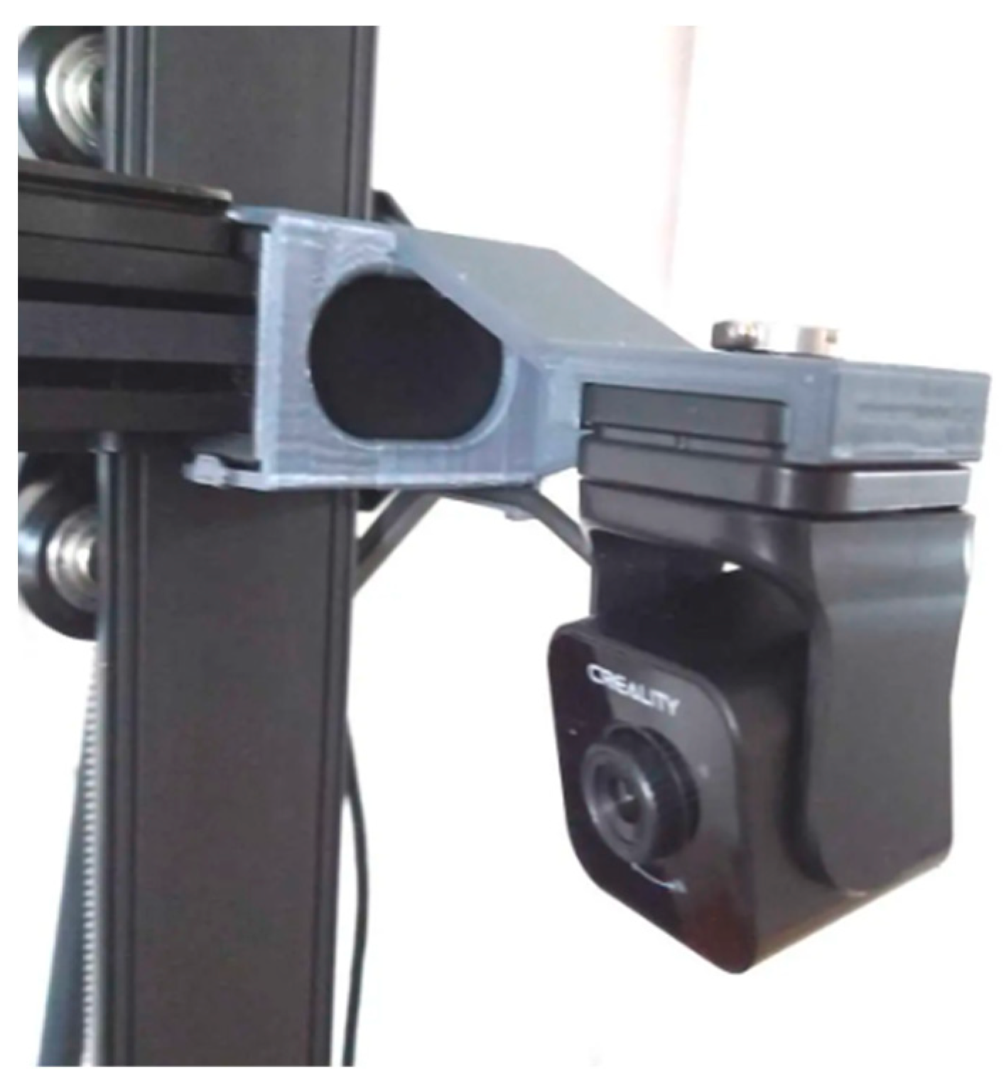
Creality offers external accessories for its printers (e.g., K1, Ender-3 V3 KE Shenzen Creality 3D Technology Co., Ltd., China, Shenzen) called Nebula cameras (Figure 4). This camera is a separate module that connects via USB or a special port and is usually attached to the corner of the printer using a magnet or holder. It is positioned to have the best view of the print, often from the top of the frame.
The Nebula camera has a resolution of 1080p and works with the Nebula AI system Nebula AI Inc., Montreal, Quebec, which, like Bambu Lab, monitors printing and looks for potential problems. Alerts are displayed via Creality Cloud, where the camera streams video and images. The camera can detect errors such as nozzle overload, layering defects, printing into air, etc. [42].
Figure 4. Nebula camera construction on a Creality printer [43].
Applsci 15 09286 g004

4.1. Types of Endoscopic Cameras

We decided to use endoscopic cameras to monitor the printing process, as they are widely used in the medical field for invasive procedures. However, they can also be used in other industries, such as engineering and manufacturing. Thanks to their small size, they are the perfect tool for monitoring and visual inspection in places that are difficult to access or laborious to reach. Endoscopes are divided into three basic classes based on their design characteristics: rigid, flexible, and capsule. Rigid endoscopes consist of metal tubes that do not bend, providing high-resolution imaging. Flexible endoscopes are made of soft materials such as polyurethane or silicone, which ensure flexibility. Under the casing is a stainless steel or tungsten spiral that allows the tube to bend while resisting twisting or kinking. Control in different directions is possible thanks to interconnected segments. Capsule endoscopes are used almost exclusively in medical and veterinary environments, as these devices are equipped with a miniature camera and are easy to swallow [44].

Endoscopic Camera Used in Experiment

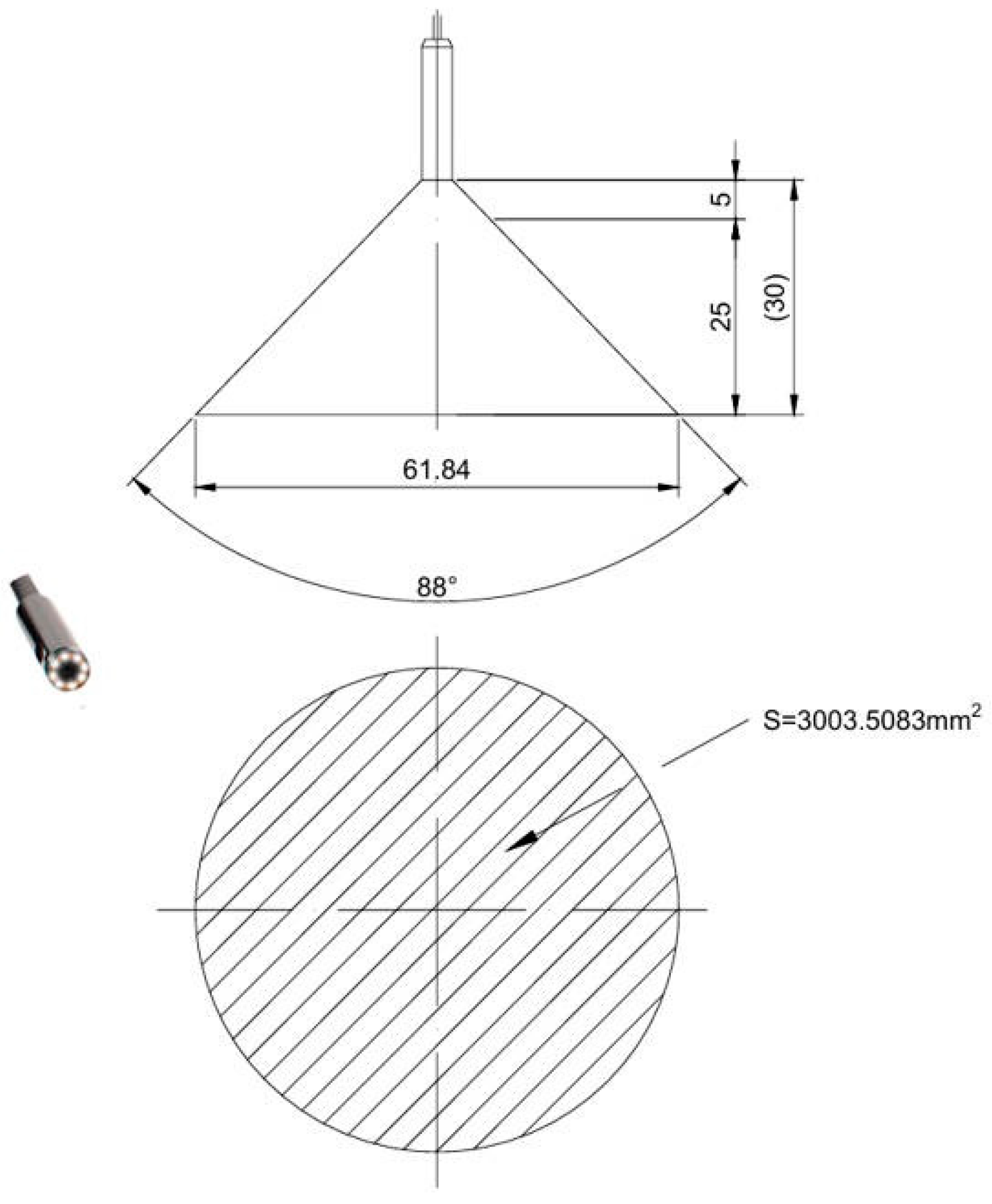
The type of endoscope used for monitoring was an EZON Shenzen Ezon Eletronics Co., Ltd., China Shenzen (EZ–EN–39S–RT) Figure 5. Using this endoscopic system, we could obtain a detailed image of the structure of the print. This allowed us to detect defects and prevent poor products at the very beginning of the defect formation stage.
The image (Figure 5) shows a sketch of the endoscopic camera used in the experiment. The 2D drawing graphically illustrates the size of the endoscopic field of view, the area that could be captured while maintaining focus, and the distance at which this was possible. The camera operated at a resolution of 1280 × 720 at 30 fps and is compatible with Windows, MAC OSX, Linux and Android systems. The camera dimensions are Ø3.9 mm × 17 mm [45].

4.2. Endoscopic Camera Placement Design

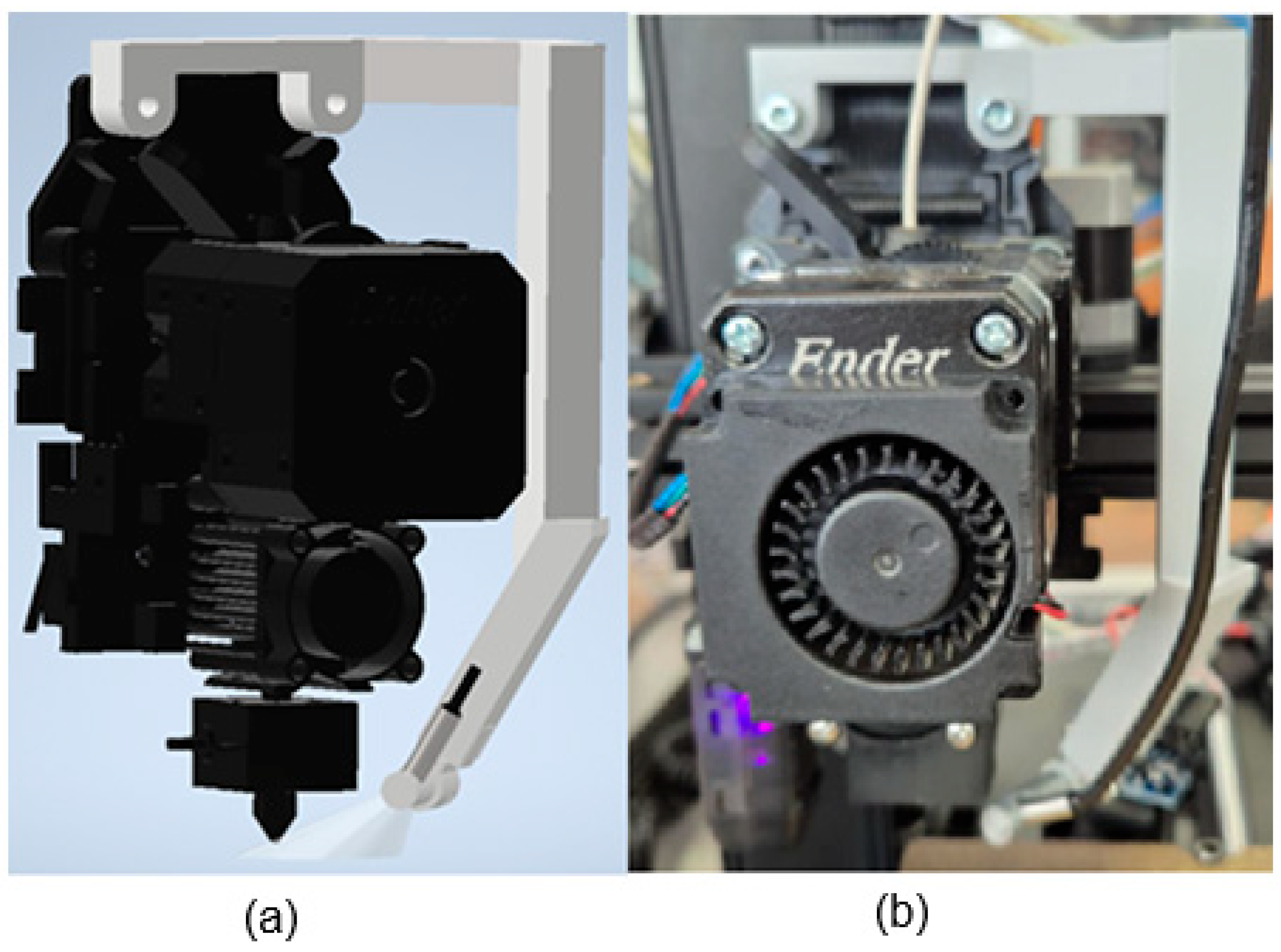
Figure 6a shows a design for a holder for an endoscopic camera. The holder consists of three parts: a main arm, a clamp and a rotating opening into which the endoscopic camera is inserted. The main arm and the endoscopic camera inlet were printed from PLA material, and silicone material was used for the clamp due to its flexible properties. The advantage of this design is the possibility of changing the angle at which the camera captures the surroundings. You can see the finished product in Figure 6b. Thanks to its dimensions and weight, the holder is light and therefore had no effect on the speed or inertial forces acting on the print head during printing. This prevented unwanted shifts or deviations in dimensions due to the holder’s influence on the overall structure of the 3D printer.

4.3. External Light Source

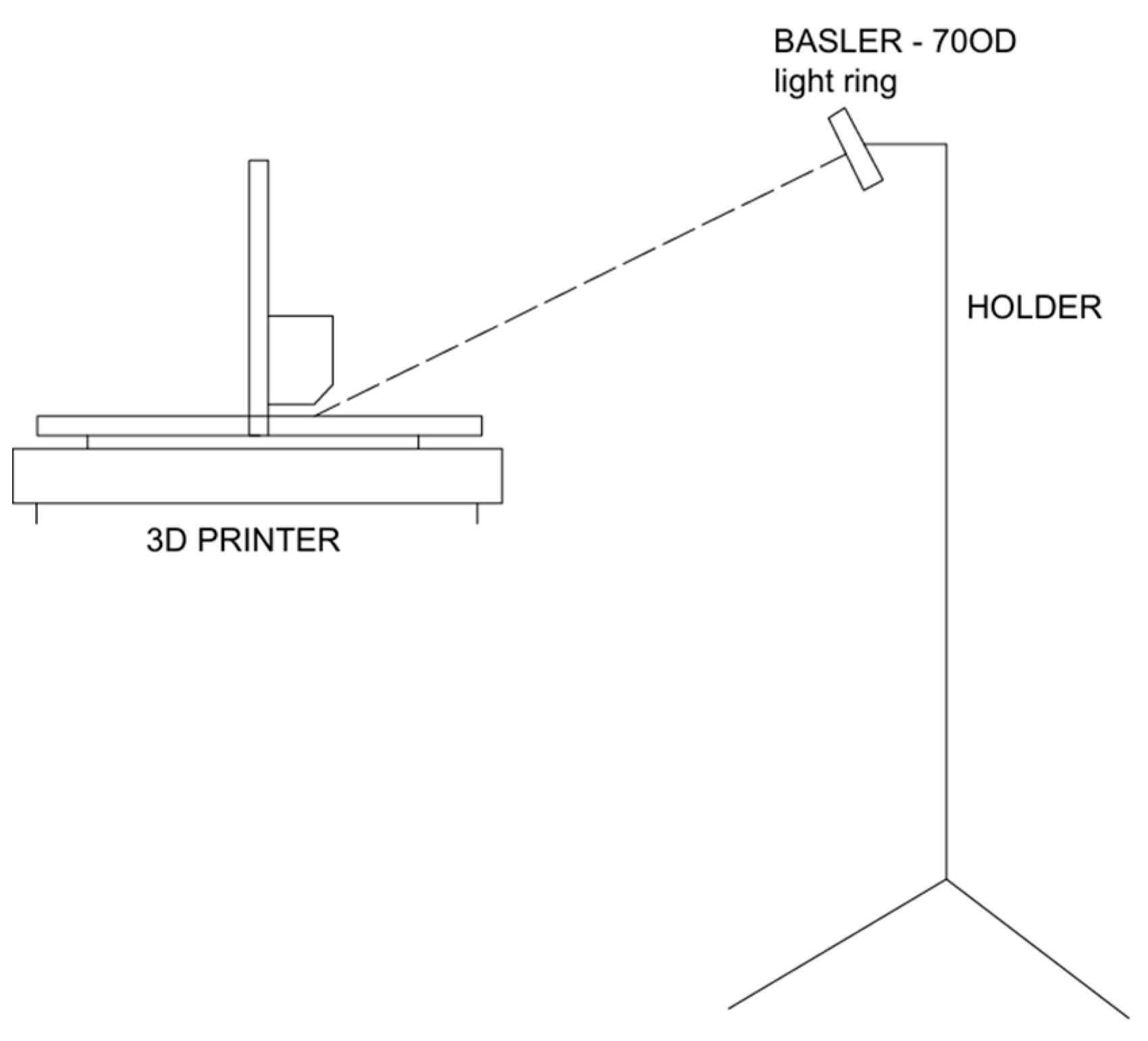
As an external light source, a Basler standard light ring (70 OD) was used to illuminate the printed area. Its location was chosen to illuminate the working area of the 3D printer without creating unwanted shadows. For this reason, we placed the light source at an angle directly above the print head from the front of the 3D printer (see Figure 7). Thanks to this lighting arrangement, all shadows fell on the scanned surface so that the print head did not interfere with the illumination of the surface being printed.

5. Training Process

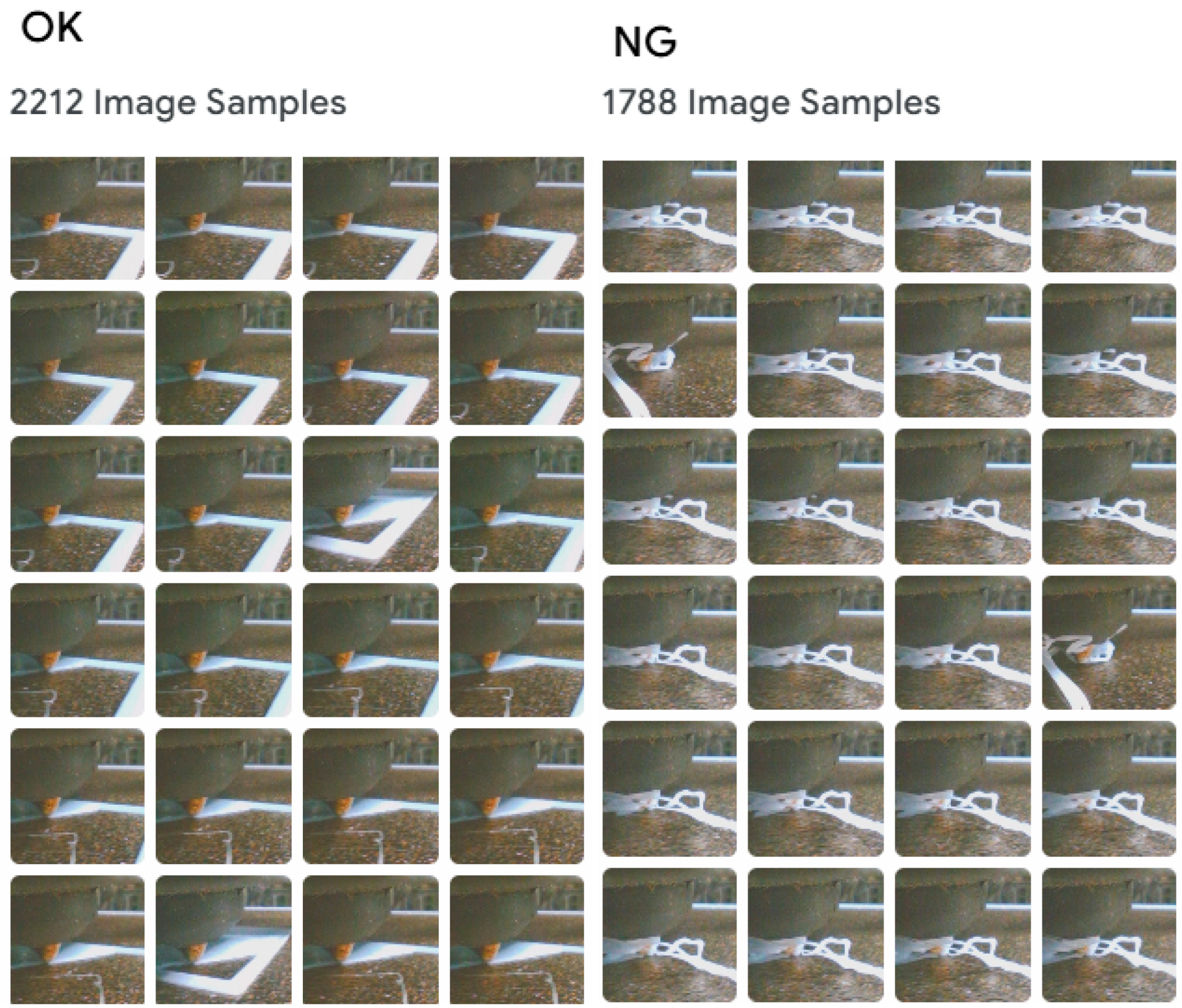
To be able to recognise the above-mentioned defects (stringing, layer shifting, non-adhesion to the surface), it was necessary to create a dataset. The dataset (Figure 8) consisted of images that captured the gradual progress of printing. For this reason, we set a Teachable Machine to take one image per second (1 fps). This gave us an extensive database of good (OK) and bad (NG) samples, which we then used to train the neural network. Since a low frame rate was set to capture the highest quality photos, it was also necessary to adjust the printing speed to prevent blurring. All samples were printed at a speed of 7 mm/s, and other parameters were also adjusted to maintain the quality of the prints, such as the feed rate and the speed of material feeding into the extruder, etc. The material used was PolyTerra PLA, 3D Manufaktura Ltd., Czech Republik, Nova Paka with the manufacturer’s recommended parameters for printing speed (30–70 mm/s), printing temperature (190–230 °C), and bed temperature (25–60 °C).

5.1. Stringing

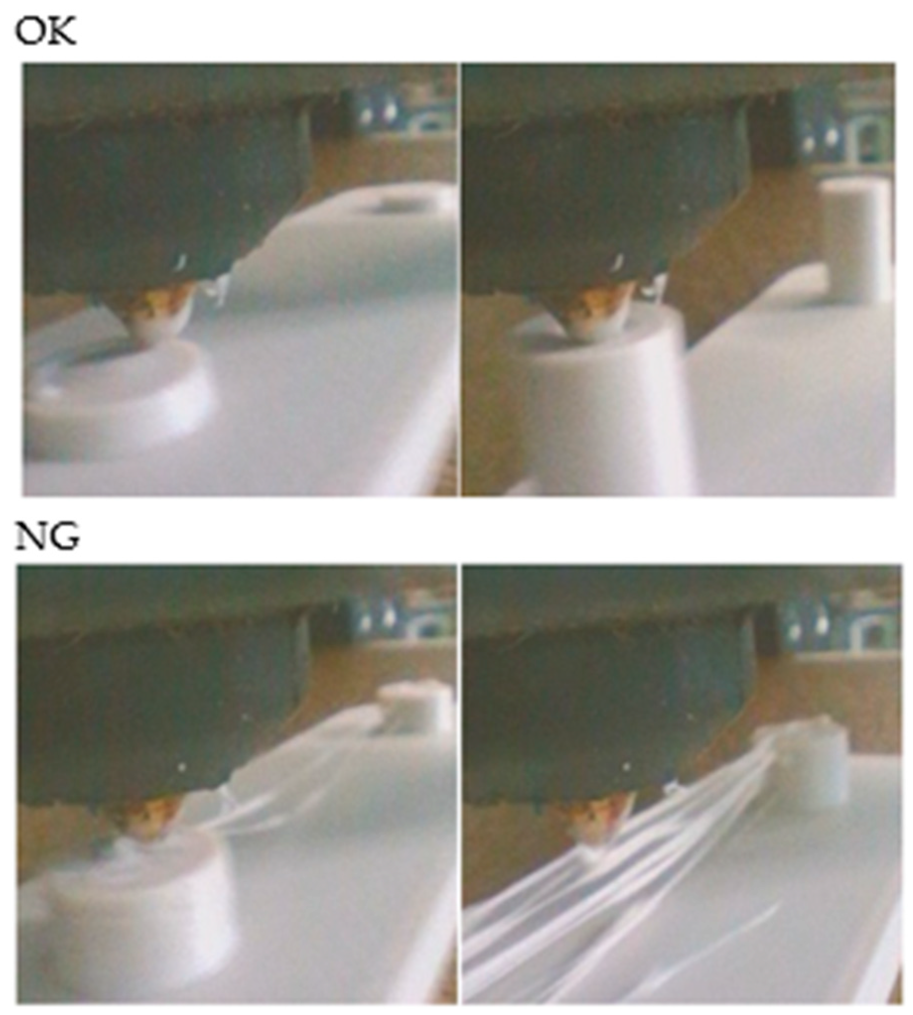
The images (Figure 9) show selected shots of good and bad samples. These samples were then used to train the system and detect defects in the final print. A total of 2678 images were captured for well-printed (OK) samples. From this total, 2230 images were selected based on their quality and suitability for training the neural network. The 2230 images were selected due to the limitations of the training programme. Next, we obtained images of printing errors (NG). A total of 1843 such images were created, all of which were used to train the neural network.

5.2. Layer Shifting

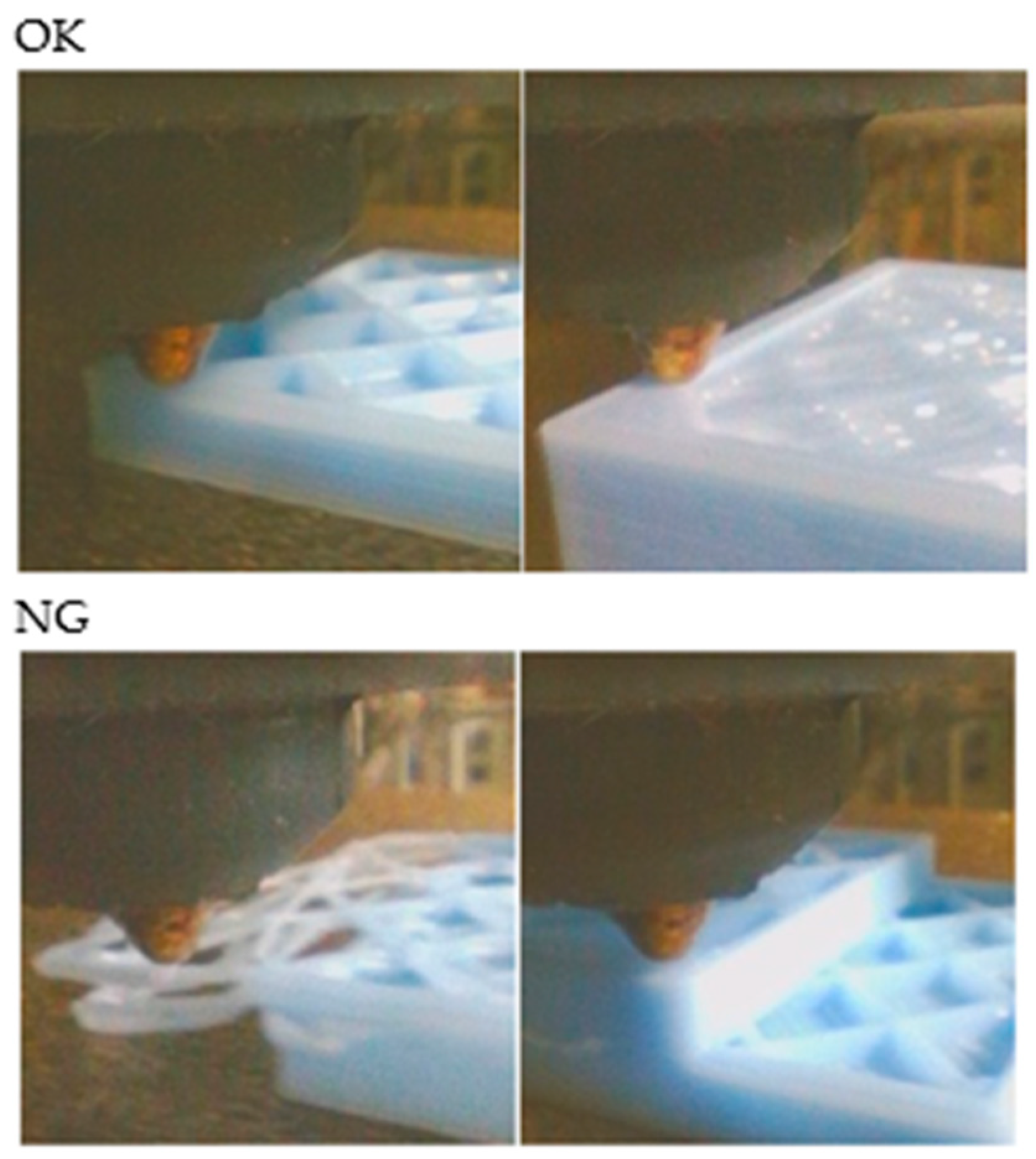
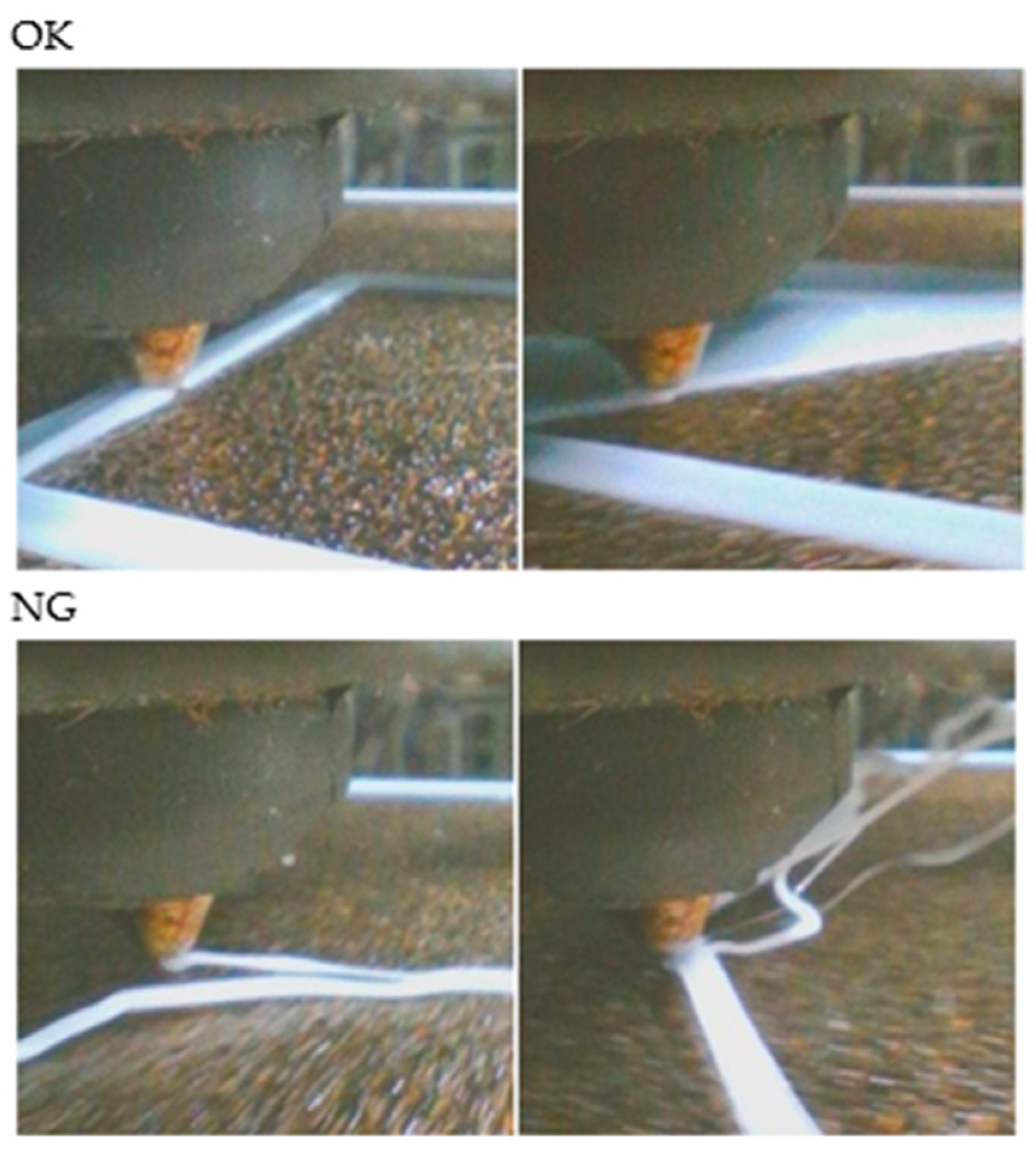
A typical geometric shape in the form of a cube with a grid filling and a filling density of 15% was used to detect layer shifts. The images (Figure 10) show how the printing of the correct (OK) and incorrect (NG) pieces proceeded. In the case of incorrect printing, an error was created in a random layer without interrupting the printing process to simulate the conditions of a randomly created defect as accurately as possible.

5.3. Adhesion to the Surface

A square sample measuring 20 × 20 mm was used to detect the non-adhesion of the first layer of material to the substrate. The sample was printed from a single layer with a thickness of 0.2 mm. To print the incorrect sample, the substrate temperature was set to 0 °C, which is one of the ways to achieve this defect and is also one of the most common occurrences. Incorrect substrate temperature settings for a given material are particularly common among beginners in 3D printing (Figure 11).

5.4. CNN

Convolutional neural networks (CNN) are a special type of deep neural network designed specifically for processing data with a spatial structure, most commonly images. They have the ability to automatically extract useful features from image inputs without the need for manual feature creation, as was common in classical machine learning [46].
CNNs work on the mathematical principle of convolution, which involves applying a small matrix, also known as a filter or kernel, to input data, such as an image. By moving this filter across the image, new activation maps are created that draw attention to certain patterns, such as edges, lines, or structures. Each filter is modified to focus on a specific type of visual feature during network training. Higher layers contain more complex objects and combinations, while the initial layers capture simple shapes [46].
An activation function—most commonly a Rectified Linear Unit (ReLU)—follows each convolutional layer and adds non-linearity to the model. To minimise computational complexity and the number of parameters, a so-called pooling layer is often used to reduce the size of the data. CNNs use multiple layers to repeat this process of convolution, activation, and pooling, allowing the network to gradually build more complex representations of the image. At the end of a CNN, there is often a fully connected layer that uses the outputs from the convolutional part of the network to classify the data using the learned features [46].
This is how Google’s Teachable Machine works, which allows non-programmers to train their own machine learning models. Teachable Machine uses a pre-trained CNN MobileNet architecture to extract salient features from photos. This model can identify broad visual patterns because it has already been trained on a large amount of image data.
Teachable Machine trains a new part of the network, specifically, a basic dense classification head which is connected to the MobileNet output after the user submits the data they want to categorise. This head consists of one or more fully connected layers that are trained to distinguish between categories specified by the user. The output is usually a SoftMax layer that assigns a probability to each class [47].

5.5. Teachable Machine

The Teachable Machine by Google (Figure 12) is an online platform that allows anyone to create their own image classification models without the need for programming. It is designed to be user-friendly and is ideal for beginners who want to get started with machine learning (ML) through a hands-on and visual approach.
Photos for each section can be added either by downloading files from your computer or by taking new photos with your webcam. The greater the variety and number of examples for each category, the better the model will perform.
Once the data have been prepared, users can start the training process with a single click. Training takes place immediately in the browser via TensorFlow.js, allowing users to adjust parameters such as the number of training epochs, batch size, and learning rate to optimise model performance. Once training is complete, the model can be evaluated immediately using new images or a live webcam feed to obtain real-time predictions and reliability metrics.

6. Results

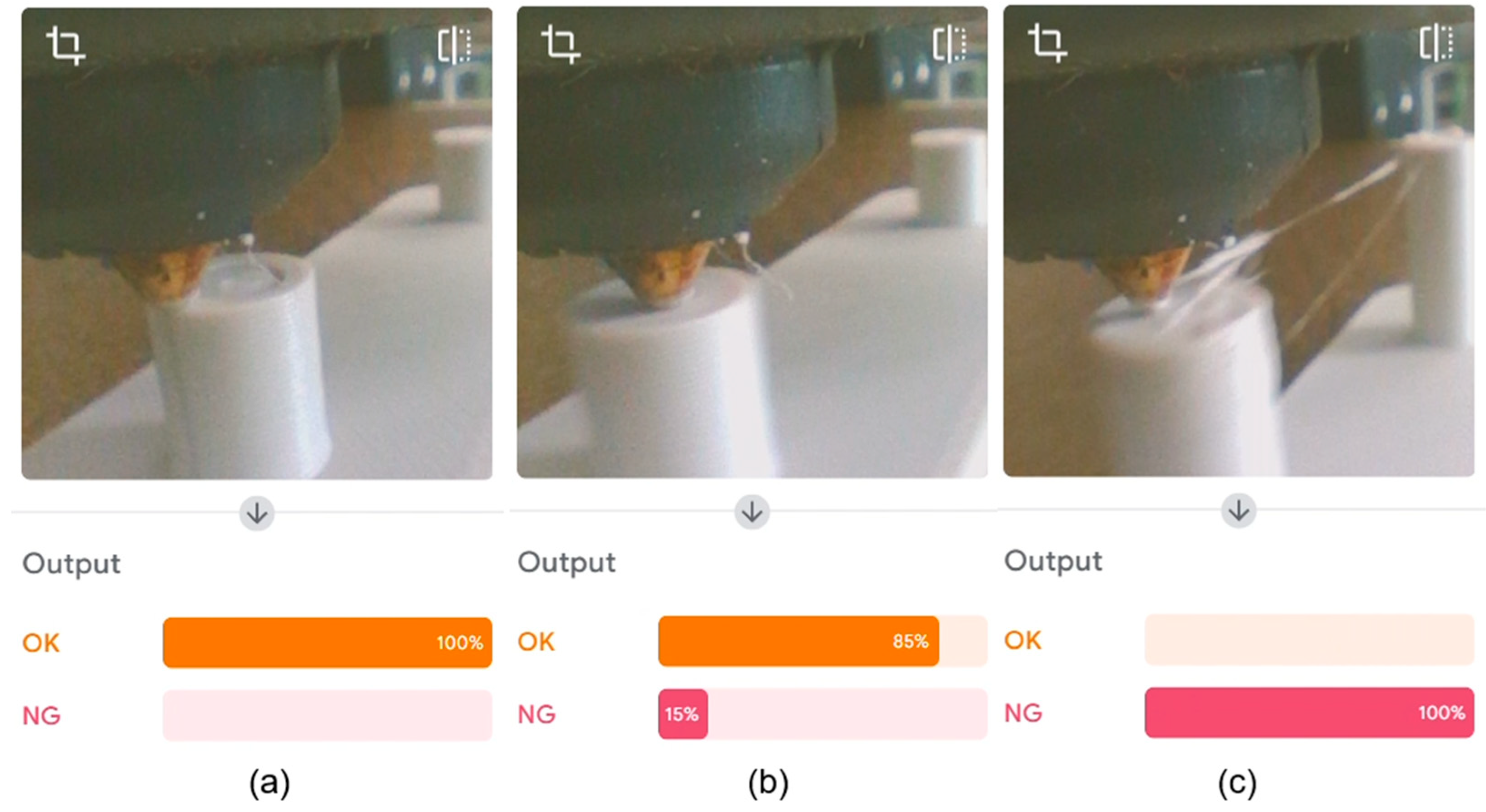
The figure shows the results of stringing detection. The experiment was based on changing parameters during printing to determine whether the program could adapt and evaluate whether an error occurred later or in a different place than where the images were recorded in the dataset. As we can see in Figure 13a, the program successfully detected that printing was proceeding correctly and no stringing was occurring. In Figure 13b, we can see stringing that occurred between two bodies, which the program successfully recorded and determined with 100% probability to be a printing error. In Figure 13c, we can see that during printing, when the extruder was in certain places, the program mistakenly detected dirt as stringing. However, these were only isolated cases and occurred for a short period of time. Even though the program incorrectly detected dirt as incipient stringing, the probability did not fall below 80%, which is still a good result. For better detection, it will be necessary to clean the extruder or, when taking pictures, also take pictures where the dirt is visible.
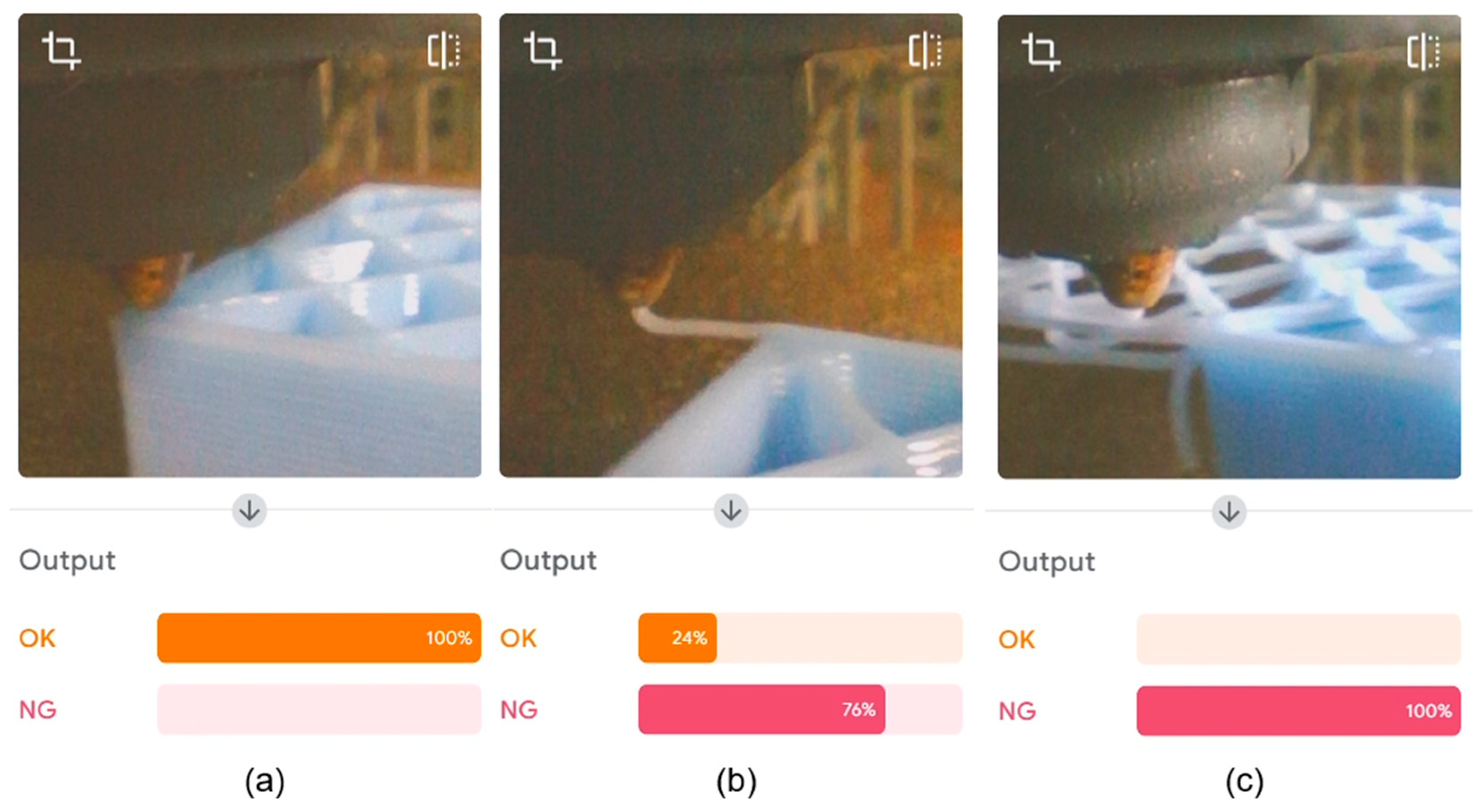
When detecting layer shifting defects, the results were very good and there was no misinterpretation of the images. As shown in Figure 14a, the camera successfully captured the correct printing process. In Figure 14b, an error was detected at a very early stage with a success rate of 76%. Figure 14c shows advanced print errors, which the camera detected and evaluated as errors with 100% success.
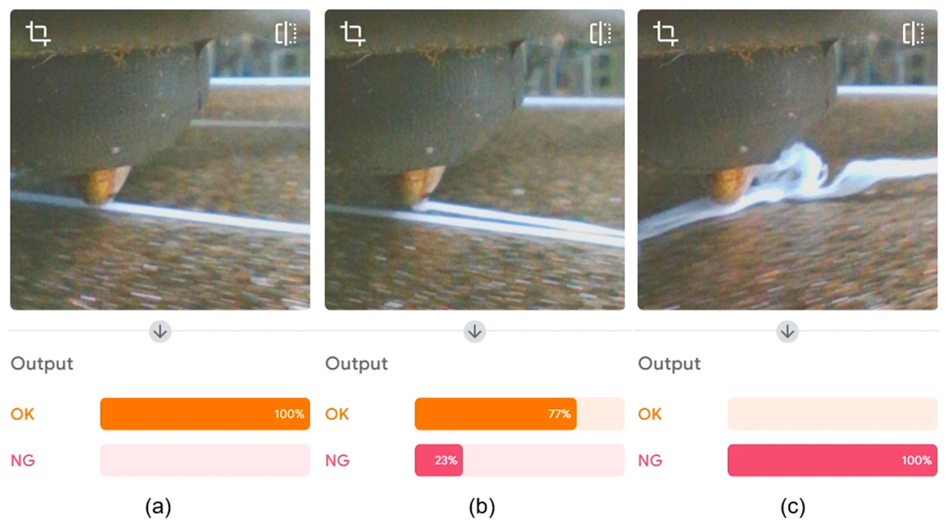
As mentioned above, a square sample with a thickness of 0.2 mm was designed to detect non-adhesion to the surface, i.e., only one layer was printed. The figure below shows how the detection proceeded. First, the first outer perimeter line Figure 15a was printed, and the camera did not detect any errors. When printing the second perimeter line (see Figure 15b), we observed a gap between the individual lines, but it was still not large enough for the program to evaluate it as an error with 100% accuracy. We recorded a 100% error rate at the start of the infill printing when the perimeter layers loosened and caught on the extruder nozzle (see Figure 15c).
A table (Table 1) was compiled from the measurement results, showing the evaluation for each measurement. The table evaluates the speed of error detection and the quality of error detection throughout the entire printing process. We can see that the fastest error detection occurred during layer shifting, when the program was able to detect the error with a very high success rate almost immediately after the deviation from the print path. The second fastest detected error was the non-adhesion of a layer to the surface, where the camera gently detected the deviation during the second circumferential layer and then, at the beginning of the fill, when it was already 100% capable of determining whether it was an error. Third was the detection of stringing, where the camera needed more visible defects to determine the error with 100% accuracy.
In terms of error detection quality, the best rating, with an excellent result, was again achieved for layer shifting detection, where the camera successfully detected not only at the beginning but also during the rest of the printing process, and there was no decrease in the percentage of error detection or false deviations. In second place was the non-adhesion to the surface error due to a low success rate in detecting the first signs of the error. However, there were no false detections when the error became more pronounced. Stringing detection ranked third with a good rating due to occasional false drops in detection success, even when the error was not yet apparent.
To quantitatively evaluate the monitoring, we decided to use the percentage success rate when the program did not achieve at least 99% successful classification or incorrect defect classification occurred. We decided to measure this in terms of time, i.e., where the time when the required percentage classification (at least 99%) was not achieved and/or when there was an incorrect classification were subtracted from the total printing time. Then, the calculated time was converted to a percentage, which corresponds to the percentage of time during printing when the classification was correct. As we can see in Table 2, the best quantitative rating was achieved in monitoring the “Layer shifting” error, where a 98.59% success rate was achieved. Overall, we can say that all monitoring results achieved very good results, i.e., above 95%.

7. Discussion

Despite the favourable results, certain limitations were identified that affect the quality of monitoring and the reliability of problem identification. The first factor is the low frame rate (1 fps), which was chosen to improve the quality of static photographs. This required reducing the printing speed to 7 mm/s. However, this decision limited the ability to print material at the speed recommended by the manufacturer, which also increased the printing time. This necessary adjustment highlights the need for future integration of a higher camera frame rate (e.g., 60 fps) while maintaining sufficient resolution.
Another critical factor is the limitation of the Teachable Machine platform, which allows a maximum of 2320 images to be uploaded to a single classification class, representing another factor affecting system performance. A solution would be to implement more advanced convolutional neural networks with the possibility of extended training on different materials, colours, and shapes of prints, which would increase the flexibility and independence of printing regarding the colour of the material and the shape of the product.
From a design point of view, the use of a flexible holder with an adjustable angle proved to be effective, allowing the camera’s field of view to be optimised without interfering with the printing area. While commonly used monitoring systems, such as cameras from Bambu Lab or Creality Nebula, use external or frame-mounted cameras and are primarily focused on wide-angle monitoring of the printing process, the solution presented in this article focuses on direct monitoring of the area around the nozzle using an endoscopic camera located directly in the print head. In the case of Bambu Lab printers, this is a fixed Full HD camera inside the print chamber that captures the entire space above the print bed. This camera is part of a closed AI system that detects common faults such as nozzle collisions with the model or warping. Similarly, Creality Nebula is an external USB-connected accessory that also monitors the process from above or from the corner of the frame. Although these systems use artificial intelligence, their view of the print area is limited and does not allow for detailed analysis of the material as it is being layered. The key advantage of our monitoring system over commercial ones is that it detects errors before they become apparent on a larger scale, as our system focuses on monitoring the layer currently being printed rather than the overall result. Our research has shown that much of the academic focus is on monitoring the 3D printing process using temperature and mechanical parameters rather than visual detection, which focuses on the layer being printed. Another advantage is that we offer guidance for industry and users of 3D printers who would like to upgrade their 3D printing and automate the inspection process using simple and accessible applications/tools. Thanks to the use of the readily available Teachable Machine program (unlike others, where AI models are closed and cannot be adapted to different materials, colour shades, or shapes), this solution offers users the ability to create their own training set and adapt the model to specific conditions without requiring any programming skills on the part of the user.

8. Conclusions

The results demonstrate the system’s capacity to detect anomalies and defects at an early stage of the 3D printing process. Using the Teachable Machine platform, even users without prior experience in machine learning were able to identify common errors thanks to the programme’s intuitive, user-friendly interface. Importantly, the accuracy of the model depends heavily on the careful selection of representative images of correctly (OK) and incorrectly (NG) printed parts to minimise false detections. Our findings indicate that successful early-stage defect detection requires image capture at the precise interface where the extruded filament bonds with either the substrate or preceding layers. Endoscopic cameras have proven particularly suitable for this purpose, as their compact dimensions allow for close placement near the extruder without obstructing the print area. Another crucial factor is high-quality illumination, which significantly improves image clarity and enables more accurate layer-by-layer analysis. A current limitation of the Teachable Machine platform is its restriction on dataset size—allowing a maximum of 2320 images per classification class. This poses challenges when training the model on prints with varied colours or materials, as the system may misclassify colour changes as defects. To address this, future work will explore the implementation of more advanced convolutional neural networks (CNNs) capable of handling greater dataset diversity and detecting defects based not only on colour but also on geometric characteristics. Additional improvements are planned for the camera mounting system. Specifically, we aim to reposition the lighting source closer to the lens to eliminate poorly lit areas and shadows. Moreover, upgrading to a camera with higher resolution and frame rate will allow for smoother tracking of print head movement and more detailed visual analysis.
In conclusion, the proposed monitoring system represents a promising step towards the automation of quality control in FDM 3D printing. While certain technical limitations remain, the approach has substantial potential for future development—particularly when integrated with adaptive AI technologies capable of responding dynamically to variable print conditions.

Author Contributions

Concept, J.P.; methodology, J.P.; software, P.L.; formal analysis, M.D.; investigation, M.K.; sources, A.N.; writing—revision and editing, M.K.; writing—original draft preparation, M.K.; supervision, K.Z.; visualisation, K.Z.; project management, J.P. All authors have read and agreed to the published version of the manuscript.

Funding

This research received no external funding.

Informed Consent Statement

Not applicable.

Data Availability Statement

Data are contained within the article.

Acknowledgments

This work was supported by the Slovak Research and Development Agency under contract No. APVV-23-0591, and by the projects VEGA 1/0700/24, KEGA 014TUKE-4/2023 granted by the Ministry of Education, Science, Research, and Sport of the Slovak Republic. This research was supported by the EU NextGenerationEU through the Recovery and Resilience Plan for Slovakia under the project No. 09I03-03-V03-00075.

Conflicts of Interest

The authors declare no conflicts of interest.

References

  1. Samykano, M.S.; Kumaresan, R.K.; Kananathan, J.K.; Kadirgama, K.K. An overview of fused filamnet fabrication technology and the advanced in PLA-biocomposites. Int. J. Adv. Manuf. Technol. 2024, 132, 27–62. [Google Scholar] [CrossRef]
  2. Mehrpouya, M.; Dehghanghadikolaei, A.; Fotovvati, B.; Vosooghnia, A.; Emamian, S.S.; Gisario, A. The Potential of Additive Manufacturing in the Smart Factory Industrial 4.0: A Review. Appl. Sci. 2019, 9, 3865. [Google Scholar] [CrossRef]
  3. Baumann, F.W.; Roller, D. Survey on Additive Manufacturing, Cloud 3D Printing and Services, Computer and Society. arXiv 2017, arXiv:1708.04875. [Google Scholar] [CrossRef]
  4. Tack, P.; Victor, J.; Gemmel, P. 3D-printing techniques in a medical setting: A systematic literature review. Biomed. Eng. Online 2016, 15, 115. [Google Scholar] [CrossRef]
  5. Kangwa, D.; Mwale, J.T.; Shaikh, J.M. Evolutionary dynamics of financial inclusion of generation z in a sub-saharan digital financial ecosystem. Copernic. J. Financ. Account. 2021, 9, 27–50. [Google Scholar] [CrossRef]
  6. Miralles, F.F.; Gual, J. Construction of scale models in industrial design: The irruption of additive manufacturing. Rubrics proposal for an objective evaluation. In Proceedings of the 11th International Conference on Education and New Learning Technologies, Palma, Spain, 1–3 July 2019. [Google Scholar] [CrossRef]
  7. Ewart, P.D. The Use of Particulate Injection Moulding for Fabrication of Sports and Leisure Equipment from Titanium Metals. Proceedings 2018, 2, 254. [Google Scholar] [CrossRef]
  8. Cortina, M.; Arrizubieta, J.I.; Ruiz, J.E.; Ukar, E.; Lamikiz, A. Latest Developments in Industrial Hybrid Machine Tools that Combine Additive and Subtractive Operations. Materials 2018, 11, 2583. [Google Scholar] [CrossRef]
  9. Schrimer, W.R.; Abendroth, M.; Roth, S.; Kühnel, L.; Zeidler, H.; Kiefer, B. Simulation-supported characterization of 3D-printed biodegradable structures. GAMM-Mitteilungen 2021, 44, e202100018. [Google Scholar] [CrossRef]
  10. Blakey-Milner, B.; Gradl, P.; Snedden, G.; Brooks, M.; Pitot, J.; Lopez, E.; Leary, M.; Berto, F.; Plessis, A. Metal additive manufacturing in aerospace: A review. Mater. Des. 2021, 209, 110008. [Google Scholar] [CrossRef]
  11. Trucco, D.; Sharma, A.; Manferdini, C.; Gabusi, E.; Petretta, M.; Giovanna, D.; Ricotti, L.; Chakraborty, J.; Lisignol, G. Modeling and Fabrication of Silk Fibroin–Gelatin-Based Constructs Using Extrusion-Based Three-Dimensional Bioprinting. ACS Biomater. Sci. Eng. 2021, 7, 3306–3320. [Google Scholar] [CrossRef] [PubMed]
  12. Rasheed, A.; San, O.; Kvamsdal, T. Digital Twin: Values, Challenges and Enablers From a Modeling Perspective. IEEE Access 2020, 8, 21980–22012. [Google Scholar] [CrossRef]
  13. Ziev, T.; Vaishnav, P. Expert elicitation to assess real-world productivity gains in laser powder bed fusion. Rapid Prototyp. J. 2024, 31, 344–358. [Google Scholar] [CrossRef]
  14. Presz, W.; Szostak-Staropiętka, R.; Dziubińska, A.; Kołacz, K. Ultrasonic Atomization as a Method for Testing Material Properties of Liquid Metals. Materials 2024, 17, 6109. [Google Scholar] [CrossRef]
  15. Tariq, U.; Joy, R.; Wu, S.H.; Mahmood, A.M.; Malik, A.; Liou, F. A state-of-the-art digital factory integrating digital twin for laser additive and subtractive manufacturing processes. Rapid Prototyp. J. 2023, 29, 2061–2097. [Google Scholar] [CrossRef]
  16. Crespo, R.N.F.; Cannizzaro, D.; Bottaccioli, L.; Macii, E.; Patti, E.; Di Cataldo, S. A Distributed Software Platform for Additive Manufacturing. In Proceedings of the IEEE 28th International Conference on Emerging Technologies and Factory Automation, Sinaia, Romania, 12–15 September 2023; pp. 1–4. [Google Scholar] [CrossRef]
  17. Liu, C.; Wang, R.; Kong, J.Z.; Suresh, B.; Chase, J.; James, F. Real-Time 3D Surface Measurement in Additive Manufacturing Using Deep Learning. In Proceedings of the Solid Freeform Fabrication 2019: Proceedings of the 30th Annual InternationalSolid Freeform Fabrication Symposium: An Additive Manufacturing Conference, Austin, TX, USA, 12–14 August 2019. [Google Scholar] [CrossRef]
  18. Nazir, A.; Gokcekaya, O.; Billah, M.K.; Ertugrul, O.; Jiang, J.; Sun, J.; Sargana, H.S. Multi-material additive manufacturing: A systematic review of design, properties, applications, challenges, and 3D Printing of materials and cellular metamaterials. Mater. Des. 2023, 226, 111661. [Google Scholar] [CrossRef]
  19. Pillai, S.; Upadhyay, A.; Khayambashi, P.; Farooq, I.; Sabri, H.; Tarar, M.; Lee, K.T.; Harb, I.; Zhou, S.; Wang, Y.; et al. Dental 3D-Printing: Transferring Art from the Laboratories to the Clinics. Polymers 2021, 13, 157. [Google Scholar] [CrossRef]
  20. Shi, J.; Liu, S.; Zhang, L.; Yang, B.; Shu, L.; Yang, Y.; Ren, M.; Wang, Y.; Chen, J.; Chen, W.; et al. Smart Textile-Integrated Microelectronic Systems for Wearable Applications. Adv. Mater. 2019, 32, 1901958. [Google Scholar] [CrossRef] [PubMed]
  21. Takahashi, H.; Punpongsanon, P.; Kim, J. Programmable Filament: Printed Filaments for Multi-material 3D Printing. In UIST ’20, Proceedings of the 33rd Annual ACM Symposium on User Interface Software and Technology, Virtual Event, 20–23 October 2020; Association for Computing Machinery: New York, NY, USA, 2020; pp. 1209–1221. [Google Scholar] [CrossRef]
  22. Hrehova, S.; Husár, J.; Duhančík, M. Characteristics of Selected Software Tools for the Design of Augmented Reality Models. In Proceedings of the 25th International Carpathian Control Conference (ICCC), Krynica Zdrój, Poland, 22–24 May 2024; pp. 1–6. [Google Scholar] [CrossRef]
  23. Duhančík, M.; Židek, K.; Husár, J. The Automated Quality Control of 3D Printing using Technical SMART Device. In Proceedings of the 25th International Carpathian Control Conference (ICCC), Krynica Zdrój, Poland, 22–24 May 2024; pp. 1–6. [Google Scholar] [CrossRef]
  24. Buj-Corral, I.; Bagheri, A.; Domínguez-Fernández, A.; Casado-Lopéz, R. Influence of infill and nozzle diameter on porosity of FDM printed parts with rectilinear grid pattern. Procedia Manuf. 2019, 41, 288–295. [Google Scholar] [CrossRef]
  25. Wawryniuk, Z.; Brancewicz-Steinmetz, E.; Sawicki, J. Revolutionizing transportation: An overview of 3D printing in aviation, automotive, and space industries. Int. J. Adv. Manuf. Technol. 2024, 134, 3083–3105. [Google Scholar] [CrossRef]
  26. Jena, M.C.; Mishra, S.K.; Moharana, H.S. Application of 3D printing across various fields to enhance sustainable manufacturing. Sustian. Social Dev. 2024, 2, 2864. [Google Scholar] [CrossRef]
  27. Brooks, H.; Ulmeanu, E.M.; Piorkowski, B. Research towards high speed extrusion freeforming. Int. J. Rapid Manuf. 2013, 3, 154–171. [Google Scholar] [CrossRef]
  28. Ranjan, N.; Kumar, V.; Ozdemir, B.O. Chapter 1—3D to 4D printing: Perspective and development. In Woodhead Publishing Series in Composites Science and Engineering 4D Printing of Composites Methods and Applications; Woodhead Publishing: Sawston, UK, 2024; pp. 1–21. [Google Scholar] [CrossRef]
  29. Základné Pojmy V 3d Tlači. 2020. Available online: https://www.materialpro3d.sk/blog/pojmy-v-3d-tlaci/ (accessed on 2 December 2022).
  30. How Does the UP 3D Printer’s Print Head (Extruder) Work? 2014. Available online: https://3dprintingsystems.freshdesk.com/support/solutions/articles/4000003132-how-does-the-up-3d-printer-s-print-head-extruder-work- (accessed on 3 October 2014).
  31. Padró, A.; Gall Trabal, G. Design and Manufacturing of a Selective Laser Sintering Test Bench to Test Sintering Materials; UPCommons: Barcelona, Spain, 2016; pp. 1–146. Available online: https://upcommons.upc.edu/entities/publication/f70b3458-0e4c-49ca-9734-f202c024f667 (accessed on 29 June 2025).
  32. Zhai, H.; Wu, Q.; Xiong, K.; Yoshikawa, N.; Sun, T.; Grattan, T.V.K. Investigation of the viscoelastic effect on optical-fiber sensing and its solution for 3D-printed sensor packages. Appl. Opt. 2019, 58, 4306–4314. [Google Scholar] [CrossRef]
  33. Utilization of Recycled Filament for 3D Printing for Consumer Goods. 2020. Available online: https://scholarworks.uark.edu/ampduht/13 (accessed on 5 May 2020).
  34. Michiels, S.; Dhollander, A.; Lammens, N.; Depuydt, T. Towards 3D printed multifunctional immobilization for proton therapy: Initial materials characterization. Med. Phys. 2016, 43, 5392–5402. [Google Scholar] [CrossRef] [PubMed]
  35. Židek, K.; Duhančík, M.; Hrehova, S. Real-Time Material Flow Monitoring in SMART Automated Lines using a 3D Digital Shadow with the Industry 4.0 Concept. In Proceedings of the 25th International Carpathian Control Conference (ICCC), Krynica Zdrój, Poland, 22–24 May 2024; pp. 1–6. [Google Scholar] [CrossRef]
  36. Identifying an Optimization Technique for Maker Usage to Address COVID-19 Supply Shortfalls. 2021. Available online: https://trace.tennessee.edu/utk_graddiss/7015 (accessed on 2 December 2021).
  37. Walsh, J.; Ranmal, S.R.; Ernest, T.B.; Liu, F. Patient acceptability, safety and access: A balancing act for selecting age-appropriate oral dosage forms for paediatric and geriatric populations. Int. J. Pharm. 2018, 536, 547–562. [Google Scholar] [CrossRef] [PubMed]
  38. Delli, U.; Chang, S. Automated Process Monitoring in 3D Printing Using Supervised Machine Learning. Procedia Manuf. 2018, 26, 865–870. [Google Scholar] [CrossRef]
  39. Simplify3D. Available online: https://www.simplify3d.com/resources/print-quality-troubleshooting/stringing-or-oozing/ (accessed on 29 June 2025).
  40. Spaghetti Detection. 2025. Available online: https://wiki.bambulab.com/en/knowledge-sharing/Spaghetti_detection (accessed on 11 June 2024).
  41. Bambu A1 Camera Relocator. Available online: https://makerworld.com/en/models/473954-bambu-a1-camera-relocator#profileId-384156 (accessed on 24 May 2025).
  42. Creality Nebula Camera Review. 2024. Available online: https://in3d.org/creality-nebula-camera-review/ (accessed on 5 March 2024).
  43. Creality Nebula Camera Holder for Ender-3 V3 KE(/SE). Available online: https://www.thingiverse.com/thing:6574108 (accessed on 3 April 2024).
  44. What Is an Endoscopy. Available online: https://www.healthline.com/health/endoscopy (accessed on 4 August 2017).
  45. Portable Industrial Endoscope. Available online: https://www.ezon-endosope.com/industrial-endoscope/portable-industrial-endoscope.html (accessed on 29 June 2025).
  46. Lecun, Y.; Bottou, L.; Bengio, Y.; Haffner, P. Gradient-based learning applied to document recognition. Proc. IEEE 1998, 86, 2278–2324. [Google Scholar] [CrossRef]
  47. Teachable Machine. Available online: https://teachablemachine.withgoogle.com/ (accessed on 29 June 2025).
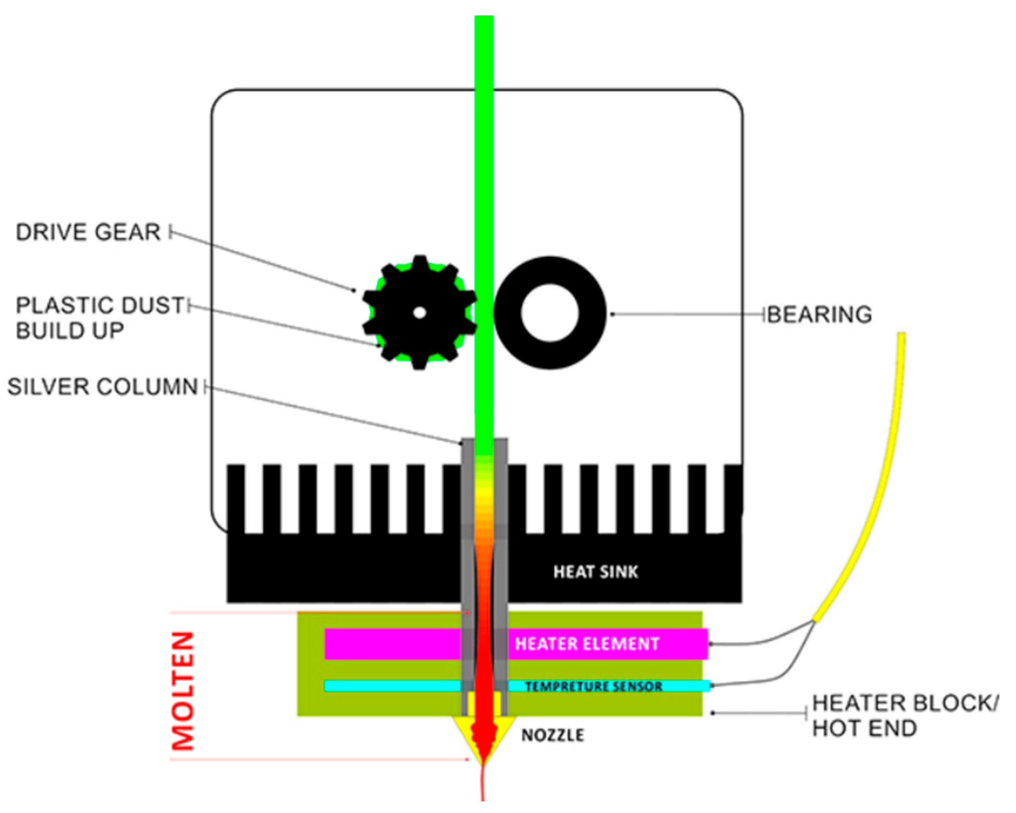
Figure 1. Print head [30].
Applsci 15 09286 g001
Figure 2. Examples of errors occurring during 3D printing: (a) Layer shifting (b) Adhesion to the surface (c) Stringing [39].
Applsci 15 09286 g002
Figure 5. Endoscope EZON (EZ–EN–39S–RT).
Applsci 15 09286 g005
Figure 6. Construction of holder (a) 3D model of holder (b) Final holder.
Applsci 15 09286 g006
Figure 7. External lighting placement.
Applsci 15 09286 g007
Figure 8. Dataset of non-adhesion to surface.
Applsci 15 09286 g008
Figure 9. Images of good (OK) and bad (NG) samples (due to stringing).
Applsci 15 09286 g009
Figure 10. Images of good (OK) and bad (NG) samples (due to layer shifting).
Applsci 15 09286 g010
Figure 11. Images of good (OK) and bad (NG) samples (due to non-adhesion to the surface).
Applsci 15 09286 g011
Figure 12. Teachable Machine working platform.
Applsci 15 09286 g012
Figure 13. Detection–stringing (a) good printing (b) incorrect detection (c) bad printing.
Applsci 15 09286 g013
Figure 14. Detection–layer shifting (a) good printing (b) first detection (c) bad printing.
Applsci 15 09286 g014
Figure 15. Detection–adhesion to the surface (a) good printing (b) first detection (c) bad printing.
Applsci 15 09286 g015
Table 1. Error detection evaluation for selected errors.
Rating Layer ShiftingNon-Adhesion to
the Surface
Stringing
Detection rateExcellentVery goodGood
Detection qualityExcellentGoodGood
Error detection position in printingAll layersFirst layerMiddle layers
Error influence to stop 3D printerAccording shifting size Instant stopChange printing parameters only
Table 2. Quantitative evaluation of measurement.
Defects Total Printing Time [s]Time of Low and Incorrect Classification [s]Percentage Success Rate [%]
Layer shifting906012898.59
Non-adhesion to surface180796.20
Stringing24774498.22
Disclaimer/Publisher’s Note: The statements, opinions and data contained in all publications are solely those of the individual author(s) and contributor(s) and not of MDPI and/or the editor(s). MDPI and/or the editor(s) disclaim responsibility for any injury to people or property resulting from any ideas, methods, instructions or products referred to in the content.