Article

RBF Neural Network-Based Anti-Disturbance Trajectory Tracking Control for Wafer Transfer Robot Under Variable Payload Conditions

Department of Mechanical Engineering, Beijing Information Science and Technology University, Beijing 102206, China
*
Author to whom correspondence should be addressed.
Appl. Sci. 2025, 15(16), 9193; https://doi.org/10.3390/app15169193 (registering DOI)
Submission received: 14 July 2025 / Revised: 18 August 2025 / Accepted: 19 August 2025 / Published: 21 August 2025

Abstract

Variations in the drive motor’s load inertia during wafer transfer robot arm motion critically degrade end-effector trajectory accuracy. To address this challenge, this study proposes an anti-disturbance control strategy integrating Radial Basis Function Neural Network (RBFNN) and event-triggered mechanisms. Firstly, dynamic simulations reveal that nonlinear load inertia growth increases joint reaction forces and diminishes trajectory precision. The RBFNN dynamically approximates system nonlinearities, while an adaptive law updates its weights online to compensate for load variations and external disturbances. Secondly, an event-triggered mechanism is introduced, updating the controller only when specific conditions are met, thereby reducing communication burden and actuator wear. Subsequently, Lyapunov stability analysis proves the closed-loop system is Uniformly Ultimately Bounded (UUB) and prevents Zeno behavior. Finally, simulations on a planar 2-DOF manipulator demonstrate significantly enhanced trajectory tracking accuracy under variable loads. Critically, the adaptive neural network control method reduces trajectory tracking error by 50% and decreases controller update frequency by 84.7%. This work thus provides both theoretical foundations and engineering references for high-precision wafer transfer robot control.

1. Introduction

The wafer transfer robot, serving as a core device in semiconductor manufacturing processes, has its trajectory tracking accuracy recognized as one of the key determinants of wafer processing yield rate and production efficiency [1,2,3,4]. Consequently, enhancing this accuracy has emerged as a central research focus within the field. However, within the highly dynamic environment of semiconductor production, variable-load conditions induce significant nonlinear inertia variations in the robot manipulator system, primarily manifested as time-varying fluctuations in the moment of inertia [5]. These inherent nonlinear dynamic characteristics complicate the design of trajectory tracking controllers [6]. Such characteristics mean that conventional control strategies based on fixed model architectures—such as PID control [7,8], backstepping control [9], adaptive backstepping control [10], LQR control [11], and even standard sliding mode control (SMC) [12]—struggle to effectively compensate for such complex time-varying disturbance. This inadequacy subsequently impacts trajectory tracking precision and system robustness [13]. To address these limitations, modern control techniques like neural networks (NNs) and their variants have emerged. As shown in a study by Ali et al. [14], an adaptive FIT-SMC approach using neural network-based friction compensation for an anthropomorphic manipulator enhances control performance, highlighting NN-based methods’ potential to overcome traditional PID control’s shortcomings. Therefore, the development of intelligent control methodologies that integrate both adaptive capability and disturbance rejection is crucial for enhancing the performance of wafer handling systems under complex operating conditions. Specifically, investigating solutions to the challenges of adaptivity [15] and disturbance rejection [16,17] in the trajectory tracking of wafer transfer robots operating under variable-load conditions—a complex working environment—represents not only the core challenge for achieving high-precision, high-reliability transport, but also serves as a critical breakthrough point for advancing semiconductor manufacturing equipment towards greater intelligence and enhanced robustness.
Recent years have witnessed extensive research on trajectory tracking control for industrial robots under variable loading conditions. The introduction of parameter uncertainties, unmodeled dynamics, and external disturbances due to load variations severely compromises tracking accuracy and system robustness. Consequently, researchers have focused on developing advanced strategies—including adaptive control, observers, neural networks, and intelligent optimization—to enhance disturbance rejection and self-regulation capabilities. Specific approaches include the following: [18] proposed an output feedback method based on backstepping control and an Extended High-Gain Observer, achieving precise tracking for a four-joint manipulator through joint estimation of unknown dynamics, though external disturbances were not considered; [19] developed a dual-loop adaptive framework to improve load adaptability for dual-arm collaborative robots, but trajectory deviations occur during high-speed motion due to inertial compensation lag; [20] integrated fast terminal sliding mode control with RBFNN to address force/position tracking for constrained mobile manipulators, with finite-time convergence proven via Lyapunov theory; [21] employed RBFNN for online disturbance identification and robust compensation, significantly enhancing tracking accuracy; [22] designed an interval type-2 fuzzy pre-compensated PID controller to suppress load transients, though challenges remain in high-dimensional parameter tuning and robustness under frequent dynamic loading.
In practical implementation, periodic control strategies requiring actuator updates at every sampling instant may cause unnecessary energy waste and mechanical wear from frequent actuation. This limitation has motivated growing interest in event-triggered control (ETC), wherein actuator states update only when specific triggering conditions are met, substantially reducing energy consumption and mechanical wear. The efficacy of ETC has been validated across diverse domains: [23] combined dynamic ETC with prescribed performance control to reduce communication load while ensuring rapid error convergence in unmanned surface vessel heading tracking; [24] proposed a 3D adaptive anti-disturbance guidance method with ETC, decreasing command update frequency via dynamic disturbance estimation and state constraints; [25] resolved fault-tolerant formation control for underactuated USVs using fixed-time observers and relative-threshold ETC, reducing control signal updates by over 90%; [26] developed an adaptive neural network ETC scheme for finite-time path following of underactuated vessels, significantly lowering controller update frequency compared to periodic triggering; [27] introduced an adaptive ETC method based on distance–velocity obstacle functions, enabling safe obstacle avoidance for unmanned vehicles through dynamically adjusted triggering intervals. Nevertheless, despite its demonstrated potential, ETC remains unexplored for dynamic load control in high-precision wafer transfer robots.
Based on this background, this paper innovatively proposes the application of RBFNN to disturbance-rejection control for n-joint wafer transfer robots under variable-load conditions. This approach aims to resolve the dual challenges of adaptivity and disturbance rejection in trajectory tracking for wafer transfer robots operating in complex variable-load environments. The main contributions of this work are outlined as follows:
(1)
This work is the first to apply RBFNN to time-varying load control in wafer transfer robot. Leveraging RBFNN’s nonlinear approximation capability, we design an adaptive control law based on a backstepping framework. By estimating system nonlinear dynamics and compensating for time-varying load disturbances online, trajectory tracking accuracy is significantly enhanced, with the steady-state error reduced by about 50%. The UUB of the closed-loop system is rigorously proven via Lyapunov theory.
(2)
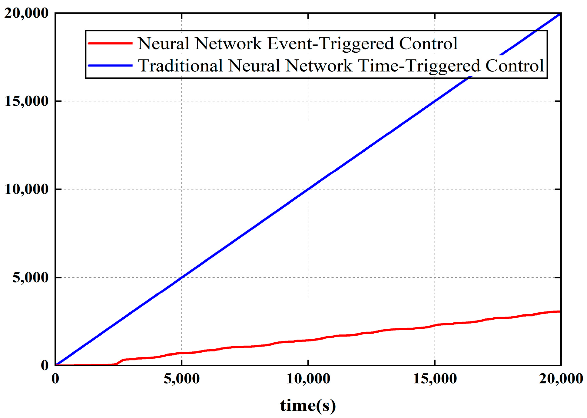
We further innovatively introduce an event-triggered mechanism with a dynamic triggering condition. This strategy updates the controller only when triggering requirements are met, reducing the number of updates from 20,000 (periodic control) to 3057, directly mitigating energy consumption.
The remainder of this paper is organized as follows. Section 2 introduces the necessary preliminaries. Section 3 elaborates in detail on the design of the adaptive event-triggered controller based on the RBF neural network. Section 4 provides a rigorous analysis based on Lyapunov stability theory, proving the stability of the closed-loop system and demonstrating the avoidance of Zeno behavior. Section 5 validates the effectiveness of the proposed control strategy through experiments conducted on the Simulink simulation platform. Finally, Section 6 concludes the paper with a thorough discussion of the findings.

2. Problem Description and Preliminaries

2.1. Variable-Load Characteristics of Wafer Transfer Robots

In semiconductor manufacturing processes, during wafer handling tasks, the end-effector of a wafer transfer robot must perform reciprocating telescopic motions. A critical issue arises: during extension/retraction, the center of mass (COM) of the wafer-loaded end-effector continuously shifts relative to the robot’s joint coordinate system. This COM offset directly induces pronounced time-varying characteristics in the load moment of inertia, mathematically expressed as J t = m r t 2 , where m is the mass of the wafer (constant) and r t is the time-varying offset distance from the COM to the joint rotation axis. As illustrated in Figure 1, this nonlinear fluctuation in the moment of inertia, caused by load variations, is a core factor affecting the trajectory tracking accuracy of the robot’s end-effector. Consequently, precisely quantifying the impact of load variations on robotic dynamic performance is a prerequisite for designing high-precision, disturbance-rejection control strategies capable of handling variable-load conditions.
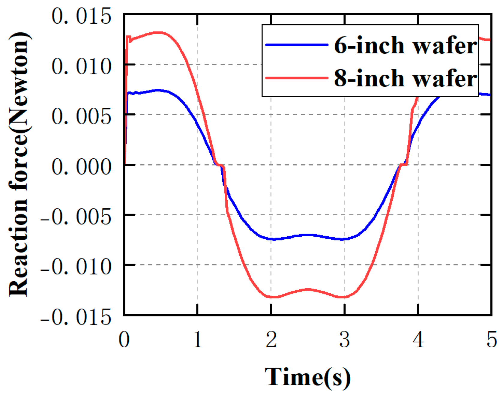
To quantitatively assess the actual impact of load variations on joint forces and system performance, this study conducted detailed dynamic simulation analysis using SolidWorks 2022 software. First, a 3D model of the wafer transfer robot was established in SolidWorks with accurate material properties. Subsequently, 6-inch and 8-inch wafer models (with distinct masses) were mounted on the robot’s end-effector to simulate dynamic variations during telescopic motion. As shown in Figure 2, when the loaded wafer size increased from 6 to 8 inches (with corresponding mass increase), the nonlinear growth of moment of inertia caused a significant amplitude increase in joint reaction forces: both mass increase and potential center-of-mass offset collectively contributed to higher load moment of inertia. As per dynamics principles, a greater moment of inertia requires larger joint torque to achieve identical angular acceleration. This directly necessitates increased drive torque output from joint motors, thereby amplifying reaction forces on the joints. As previously discussed, such load inertia increases degrade system dynamic performance (e.g., slower response) and trajectory tracking accuracy, making precise path-following at the robotic arm’s end-effector more challenging, ultimately compromising wafer transfer precision and operational stability.
The pronounced variations in joint reaction forces demonstrated in Figure 2 provide direct empirical evidence that load variations exert non-negligible substantial impacts on the critical dynamic performance (joint loading) of wafer transfer robots. This effect is intrinsically linked to trajectory tracking accuracy at the end-effector and system stability, representing a critical barrier that semiconductor manufacturing equipment must overcome to achieve high yield rates and operational efficiency. Consequently, the core objective of this study is to design a high-precision robust disturbance-rejection control strategy that addresses trajectory tracking accuracy degradation caused by load-induced time-varying moment of inertia during wafer handling, ensuring precision-stable wafer transfer.

2.2. Dynamic Model of the Wafer Transfer Robot

In establishing the dynamic model of the robotic manipulator, we made the following key assumptions: First, the manipulator is assumed to be a rigid body, with elastic deformation effects ignored. Second, joint motion is assumed to be continuously differentiable, ensuring the validity of the Lagrange modeling method. Additionally, we assume the system is primarily affected by inertial forces, Coriolis forces, and gravitational forces, with minor factors like air resistance neglected at this stage. Based on these assumptions, we employed the Lagrange method to model the manipulator’s dynamics. This approach, suitable for conservative systems, effectively describes the manipulator’s dynamic characteristics in joint space.
The Lagrange dynamic equations are then established as follows:
M q q ¨ + C q , q ˙ q ˙ + G q + τ d = τ
where q = [ q 1 , q 2 , , q n ] T R n represents the vector of joint positions (system output); q ˙ = [ q ˙ 1 , q ˙ 2 , , q ˙ n ] T R n is the vector of joint velocities; q ¨ = [ q ¨ 1 , q ¨ 2 , , q ¨ n ] T R n is the vector of joint accelerations; M ( q ) R n × n is the symmetric positive-definite inertia matrix, reflecting the mass distribution and inertial characteristics of the manipulator links; C ( q , q ˙ ) R n × n is the Coriolis and centrifugal force matrix, determined by the kinematic structure and joint velocities; G ( q ) R n is the gravitational torque vector, depending on the center of mass of each link and gravitational acceleration; τ d R n is the vector of disturbance torques; and τ = τ 1 , τ 2 , , τ n R n is the vector of control inputs applied to the robot joints.
Remark 1.
To simplify the notation, the temporal argument  t  is omitted in the subsequent expressions. All variables are implicitly functions of time, as the system’s dynamics are time-varying due to the movement of the robotic manipulator. This notation is adopted to enhance the readability of the equations without causing ambiguity.

2.3. RBFNN

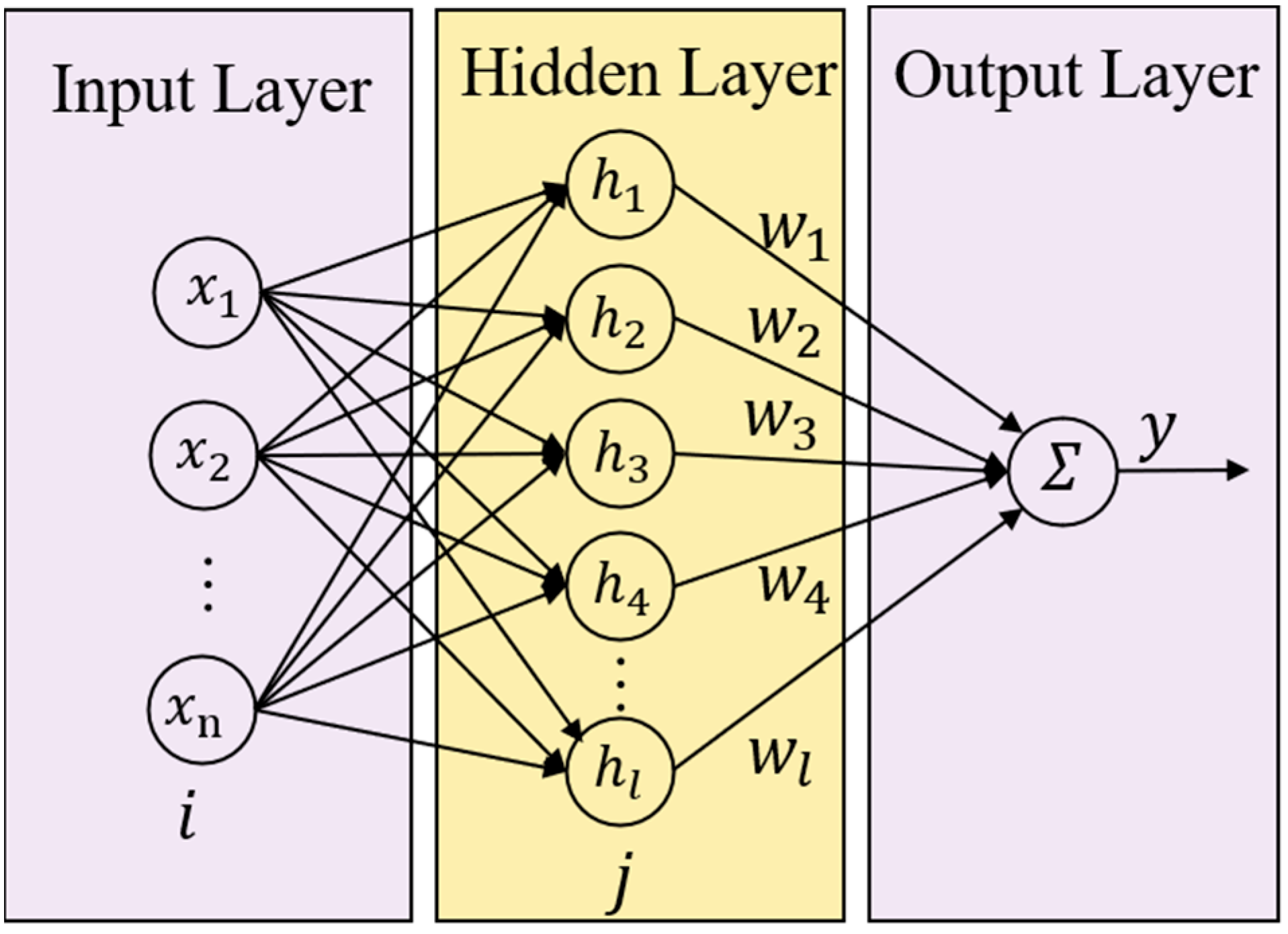
Numerous publications have confirmed [28,29] that the RBFNN possesses the capability to approximate any continuous nonlinear function with arbitrary precision on a compact set. It can be mathematically described as follows:
f = W T h ( x ) + ε
where W = [ W 1 , W 2 , , W l ] R l denotes the ideal constant weight vector of the RBFNN; x = [ x 1 , x 2 , , x l ] R l represents the input vector to the neural network; l > 1 is the number of nodes in the neural network; ε R is the approximation error, which is bounded; and h ( x ) = [ h 1 ( x ) , h 2 ( x ) , , h l ( x ) ] T R l is the basis function vector. In this paper, the Gaussian function is chosen as the basis function vector:
h j ( x ) = e x p ( x c j 2 ω j 2 ) , j = 1 , 2 , , l
where c j = [ c 1 , c 2 , , c l ] T represents the center of the Gaussian function distribution curve, and ω j is its width. In the RBFNN structure, the parameters c j and ω j play crucial roles. Specifically, c j denotes the center of the Gaussian function distribution curve, which determines the position of the peak of the Gaussian function in the input space. The parameter ω j represents the width of the Gaussian function, which controls the spread of the function and affects the overlap between adjacent basis functions. The initialization of these parameters is vital for the network’s performance. Centers c j are typically initialized using a uniform distribution to cover the input space adequately, while widths ω j are often initialized based on the standard deviation of the input data to balance the coverage and sensitivity of the network.
The structure of the RBFNN is illustrated in Figure 3.

2.4. Event-Triggered Control

In traditional time-triggered trajectory tracking control strategies, state signals (i.e., position and velocity information) are transmitted to the controller at fixed sampling intervals, and the controller executes updates periodically. This periodic transmission and update mechanism may lead to increased controller update frequency and aggravated actuator wear. In resource-constrained or engineering application scenarios [30], such a situation requires improvement. Therefore, this study introduces the event-triggered control mechanism into the trajectory tracking system of the wafer transfer robot, aiming to reduce controller update frequency and actuator wear.
Specifically, during system operation, the event-triggered mechanism evaluates the triggering condition based on system state information. Whenever the system state satisfies the event-triggering condition, the control input is updated at that moment, which is referred to as the current event-triggering instant. When the system state does not meet the triggering condition, the control input maintains the value generated at the latest event-triggering instant under the action of a zero-order holder until the next update, that is,
u ( t i ) = u ( t k i ) , t [ t k i , t ( k + 1 ) i )
In the equation, t k i , k = 1 , 2 , denotes the event-triggered sequence. The control input update method in Equation (4) represents the event-triggered mechanism.
Note: In event-triggered control, “Zeno behavior” refers to the phenomenon where the number of triggers increases infinitely within a finite time interval, and the inter-event intervals asymptotically approach zero. This behavior contradicts the design purpose of event-triggered mechanisms. Therefore, it is essential to prove the existence of a minimum inter-event interval through computation to ensure the system is Zeno-free.

2.5. Properties, Assumptions, and Lemmas

Property 1
[31].  M ˙ 2 C is a skew-symmetric matrix, i.e., for any  x R n , the following holds:  x T ( M ˙ 2 C ) x = 0 .
Property 2
[31]. The inertia matrix M is symmetric positive definite, and there exist λ min M and λ max M , such that λ min ( M )   x 2 x T M x λ max ( M ) , x R n .
Assumption 1.
The desired trajectory y d  and y ˙ d  are bounded and differentiable.
Assumption 2.
The velocity vector q ˙  and acceleration vector q ¨  are measurable.
Lemma 1
[32] (Young’s Inequality). For any b 1 R , any b 2 R , and any ε > 0 , if constants a > 0 , c > 0 satisfy 1 a + 1 c = 1 , then
b 1 b 2 ε a a | b 1 | a + 1 c ε c | b 2 | c
Lemma 2
[33]. For any ρ R and arbitrary positive parameter β , the following inequality holds:
0 ρ ρ tanh ρ β 0.2785 β
Lemma 3
[34] (UUB). Suppose the Lyapunov function V x is positive definite and continuous. If it satisfies
φ 1 x V x φ 2 x , V ˙ x ρ V x + δ
then x converges to a bounded closed set called the UUB set. Here,  ρ , δ > 0 are constants, and  φ 1 , φ 2 are functions mapping  R n to R .
Remark 2.
Assumption 1 (the desired trajectory and its derivatives are bounded and differentiable) is highly feasible. Because the desired trajectory is manually designed or planned, a smooth trajectory (such as a polynomial or spline curve) can be selected, and its velocity and acceleration can be ensured not to exceed the physical limits of the system.
Remark 3.
Assumption 2 (angles and angular velocities are measurable) is usually feasible in modern systems. Angles can be directly measured by encoders, etc. Angular velocity can be directly measured through a gyroscope, or obtained by filtering and differentiating the angle signal. The feasibility of this assumption is highly dependent on the system budget and sensor configuration. It is achievable in most standard control systems, but algorithmic compensation may be needed in extreme scenarios.

3. Control Design

3.1. Controller Design

Transform Equation (1) into state-space form. Define x 1 = [ x 11 , x 12 , , x 1 n ] T = [ q 1 , q 2 , , q n ] T , x 2 = [ x 21 , x 22 , , x 2 n ] T = [ q ˙ 1 , q ˙ 2 , , q ˙ n ] T . The state-space representation is
x ˙ 1 = x 2 x ˙ 2 = M 1 τ C x 2 G τ d y = x 1
Next, we introduce the system tracking error:
e 1 = y y d e 2 = x 2 α
In the equation, e 1 = [ e 11 , e 12 , , e 1 n ] T R n is the system position error vector, e 2 = [ e 21 , e 22 , , e 2 n ] T R n is the system velocity error vector, y d = [ y d 1 , y d 2 , , y d n ] T R n is the desired trajectory vector, and α = [ α 1 , α 2 , , α n ] T R n is the virtual control law to be designed.
Taking the derivative of the system errors:
e ˙ 1 = e 2 + α y ˙ d e ˙ 2 = M 1 τ C x 2 G τ d α ˙
Lyapunov Function V 1 Selection:
V 1 = 1 2 e 1 T e 1
Derivative of V 1 :
V ˙ 1 = e 1 T e 2 + α y ˙ d
Design of Virtual Control Law:
α = y ˙ d k 1 e 1
where α = [ α 1 , α 2 , , α n ] T , k 1 = d i a g k 11 , k 12 , , k 1 n ,   k i > 0 ,   i = 1 , 2 , , n being the parameter matrix to be designed.
Substituting (12) into (11) yields:
V ˙ 1 = k 1 e 1 T e 1 + e 1 T e 2
If e 2 = 0 , 0 , , 0 T , then: V ˙ 1 = k 1 e 1 T e 1 0 . According to Lyapunov’s Stability Theorem, the system is stable when e 2 ≡ 0.
Lyapunov function V 2 selection:
V 2 = V 1 + 1 2 e 2 T M e 2
Derivative of V 2 :
V ˙ 2 = V ˙ 1 + 1 2 e 2 T M ˙ e 2 + e 2 T M e ˙ 2 = k 1 e 1 T e 1 + e 1 T e 2 + 1 2 e 2 T M ˙ e 2 + e 2 T τ C x 2 G τ d M α ˙ = k 1 e 1 T e 1 + e 1 T e 2 + 1 2 e 2 T M ˙ e 2 + e 2 T τ C e 2 C α G τ d M α ˙ = k 1 e 1 T e 1 + e 1 T e 2 + 1 2 e 2 T M ˙ 2 C e 2 + e 2 T τ C α G τ d M α ˙ = k 1 e 1 T e 1 k 2 e 2 T e 2 + e 2 T ( f f ^ )
The stabilizing control law for the velocity error subsystem is
τ = [ τ 1 , τ 2 , , τ n ] T = e 1 k 2 e 2 f ^
where k 2 = d i a g k 21 , k 22 , , k 2 n , k i > 0 , i = 1 , 2 , , n . k 2 is the parameter matrix to be designed.
In Equation (15), the term f represents the lumped unknown dynamics of the system, defined as
f X = C α G τ d M α ˙
where f X = f 1 X 1 , f 2 X 2 , , f n X n T . Since f X is a nonlinear function, it can be approximated using an RBFNN. This approach allows the neural network to compensate for model errors induced by payload variations and enhance the system’s disturbance rejection capability:
f i X i = W i T h i X i + ε i X i
where h i X i = h i 1 X i , h i 2 X i , , h i j X i T , i = 1 , 2 , , n . j = 1 , 2 , , l .   ε i ε ¯ i , ε ¯ i > 0 . The estimated output of the neural network is f ^ i = f ^ 1 , f ^ 2 , , f ^ n T = W ^ i T h i X i . Here, W is the ideal weight vector, typically inaccessible, estimated by W ^ . The weight estimation error is defined as W ˜ i = W i W ^ i , where W i = [ W i 1 , W i 2 , , W i j ] T , W ^ i = [ W ^ i 1 , W ^ i 2 , , W ^ i j ] T , W ˜ i = [ W ˜ i 1 , W ˜ i 2 , , W ˜ i j ] T , i = 1 , 2 , , n . j = 1 , 2 , , l .
Neural Network Adaptive Law Design:
W ^ ˙ i = σ i W ^ e 2 i h i
where the vector of design parameters is defined as σ i = [ σ 1 , σ 2 , , σ n ] T . Each parameter σ i , i = 1 , 2 , . n is strictly positive. To ensure the convergence of the adaptive algorithm, we utilize Lyapunov stability theory. By constructing a Lyapunov function for the weight estimation error and ensuring its derivative is negative semi-definite, we guarantee that the weight estimation error will converge to a bounded region around the ideal weights. This convergence criterion is rigorously proven in Section 4, where we demonstrate that the system states and weight estimates will asymptotically converge to a neighborhood of the equilibrium point under the designed adaptive law.
Lyapunov function V 3 selection:
V 3 = V 2 + i = 1 n 1 2 W ˜ i T W ˜ i
Derivative of V 3 :
V ˙ 3 = k 1 e 1 T e 1 k 2 e 2 T e 2 + e 2 T f ˜ + i = 1 n W ˜ i T W ^ ˙ i
where
e 2 T f ˜ + i = 1 n W ˜ i T W ^ ˙ i = i = 1 n e 2 i f ˜ i + i = 1 n W ˜ i T W ^ ˙ i = i = 1 n j = 1 l e 2 i W ˜ i j h i j + i = 1 n e 2 i ε i + i = 1 n j = 1 l W ˜ i j W ^ ˙ i j = i = 1 n j = 1 l W ˜ i j e 2 i h i j + W ^ ˙ i j + i = 1 n e 2 i ε i = i = 1 n j = 1 l σ i W ˜ i j W ^ i j + i = 1 n e 2 i ε i
based on Lemma 1, the following holds:
i = 1 n e 2 i ε i i = 1 n e 2 i ε ¯ i 1 2   i = 1 n e 2 i 2 + ε ¯ i 2
i = 1 n j = 1 l σ i W ˜ i j W ^ i j i = 1 n j = 1 l 1 2 σ i W i j 2 i = 1 n j = 1 l 1 2 σ i W ˜ i j 2
substituting Equations (23) and (24) into (21) yields:
V ˙ 3 k 1 e 1 T e 1 i = 1 n k 2 i 1 2 e 2 i 2 i = 1 n j = 1 l 1 2 σ i W ˜ i j 2 + i = 1 n 1 2 ε ¯ i 2 + i = 1 n j = 1 l 1 2 σ i W i j 2 ρ 11 1 2 e 1 T e 1 ρ 12 1 2 e 2 T M e 2 ρ 13 i = 1 n 1 2 W ˜ i T W ˜ i + δ 1
that is
V ˙ 3 ρ 1 V 3 + δ 1
where
ρ 11 = 2 min k 11 , k 12 , , k 1 n ρ 12 = 2 min k 21 1 2 , k 22 1 2 , , k 2 n 1 2 / λ max M ρ 13 = min σ 1 , σ 2 , , σ n ρ 1 = min ρ 11 , ρ 12 , ρ 13 δ 1 = i = 1 n 1 2 ε ¯ i 2 + i = 1 n j = 1 l 1 2 σ i W i j 2 , δ 1 > 0
where λ max M denotes the maximum eigenvalue of the inertia matrix M , and the design parameters satisfy k 2 i > 1 2 .
Integrating V ˙ 3 over time yields
V 3 V 3 0 δ 1 ρ 1 e ρ 1 t + δ 1 ρ 1
By Lemma 3, the closed-loop system is UUB.

3.2. Event Triggering

Define the measurement error z i t , representing the discrepancy between the controller’s triggered value and the current control input:
z k i t = ω i t τ i t , t t k i , t k + 1 i
where τ i t k i denotes the controller’s value at the previous trigger instant, which is maintained constant by a zero-order holder starting from the previous trigger instant t k i until the subsequent trigger instant t k + 1 i . When t i = t k i , it holds that z k i t = ω i t k i τ i t k i = 0 .
Consider a robotic system, define the event-triggered condition as
τ i t = ω i t k , t t k i , t k + 1 i t k + 1 i = i n f t R z i t μ i τ i t + m i
The controller parameters μ i and m i ( 0 < μ i < 1 , m i > 0 ) were selected based on a combination of system dynamics analysis and extensive simulation experiments. The sensitivity analysis of parameters μ i and m i can be found in the Appendix A. The controller’s updating time instant is marked as t k + 1 i whenever the triggering condition z k i t μ i τ i t + m i is satisfied, and the updated control signal τ i t k + 1 i is applied to the system. On the time interval t k i , t k + 1 i , the control signal remains constant at ω i t k i .
When t t k i , t k + 1 i , the neural network event-triggered control law is designed as follows:
ω i t = 1 + μ i τ i tanh e 2 i τ i β i + m ¯ i tanh e 2 i m ¯ i β i
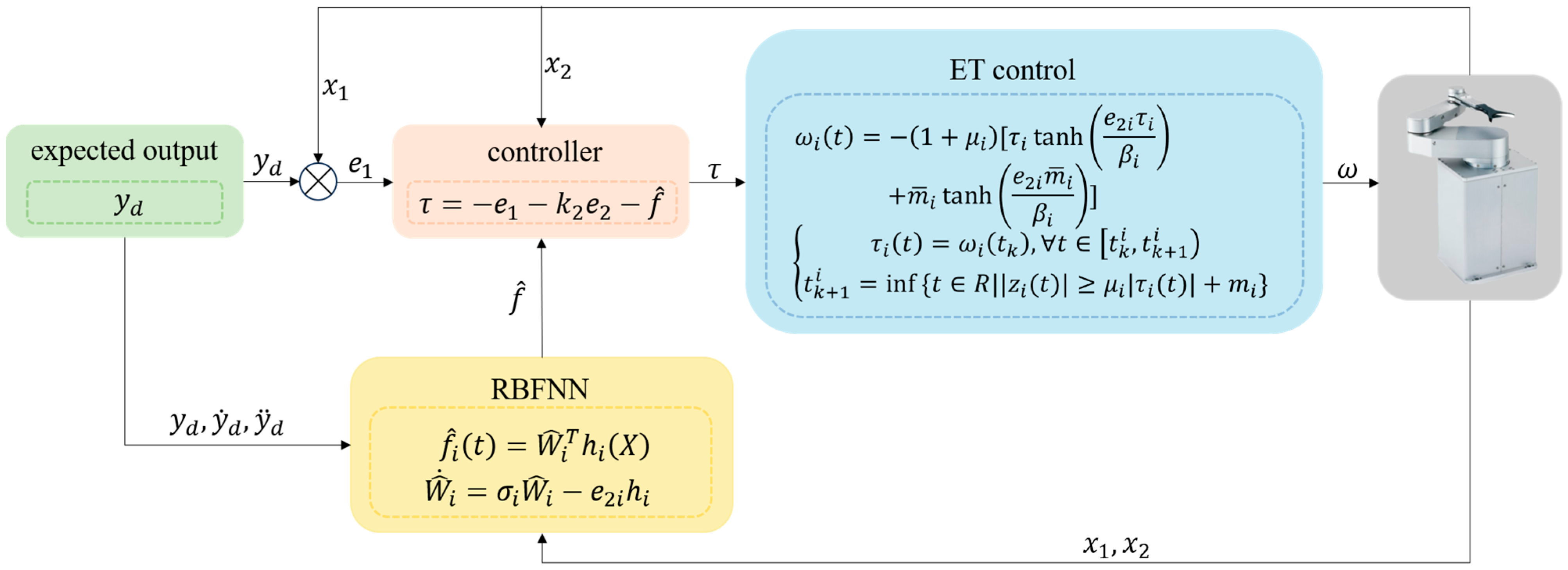
The control algorithm flowchart is shown in Figure 4.

4. Stability Analysis

Since ω i t τ i t = λ i , 1 t μ i τ i t + λ i , 2 t m i for all t t k i , t k + 1 i , there must exist continuous time-varying parameters λ i , j t k i = 0 , λ i , j t k + 1 i = ± 1 , λ i , j t 1 , i = 1 , 2 , , n , j = 1 , 2 such that ω i t τ i t = λ i , 1 t μ i τ i t + λ i , 2 t m i holds, i.e., the following equation is satisfied:
τ i t = ω i t λ i , 2 t m i 1 + λ i , 1 t μ i
Select the Lyapunov function V :
V = 1 2 e 1 T e 1 + 1 2 e 2 T M e 2 + i = 1 n 1 2 W ˜ i T W ˜ i
Differentiating V with respect to time, we obtain
V ˙ = k 1 e 1 T e 1 + e 2 T e 1 + f + e 2 T τ + i = 1 n W ˜ i T W ^ ˙ i
Substituting Equation (31) into Equation (33) yields
V ˙ k 1 e 1 T e 1 + e 2 T e 1 + f + i = 1 n e 2 i ω i t λ i , 2 t m i 1 + λ i , 1 t μ i + i = 1 n W ˜ i T W ^ ˙ i
Since λ i , 1 t 1 , 1 and λ i , 2 t 1 , 1 , by Lemma 1, we have
i = 1 n e 2 i λ i , 2 t m i 1 + λ i , 1 t μ i i = 1 n e 2 i λ i , 2 t m i 1 + λ i , 1 t μ i i = 1 n e 2 i m i 1 μ i i = 1 n e 2 i m ¯ i i = 1 n 1 2 m ¯ i 2 + e 2 i 2
here, m ¯ i > m i 1 μ i , m ¯ i is a design parameter.
Substituting the event-triggered control law of the neural network (30) and Equation (35) into Equation (34) yields
V ˙ k 1 e 1 T e 1 + e 2 T e 1 + f + i = 1 n e 2 i 1 + μ i 1 + λ i , 1 t μ i τ i tanh e 2 i τ i β i + m ¯ i tanh e 2 i m ¯ i β i + i = 1 n 1 2 m ¯ i 2 + e 2 i 2 + i = 1 n W ˜ i T W ^ ˙ i
then, define
g i = 1 + μ i 1 + λ i , 1 t μ i
And 1 g i 1 + μ i 1 μ i .
Substituting (37) into (36) gives
V ˙ k 1 e 1 T e 1 + e 2 T e 1 + f + i = 1 n g i e 2 i τ i tanh e 2 i τ i β i + e 2 i m ¯ i tanh e 2 i m ¯ i β i + i = 1 n 1 2 m ¯ i 2 + e 2 i 2 + i = 1 n W ˜ i T W ^ ˙ i
From Lemma 2, we have
e 2 i τ i tanh e 2 i τ i β i 0.2785 β i e 2 i τ i
e 2 i m ¯ i tanh e 2 i m ¯ i β i 0.2785 β i e 2 i m ¯ i
Substituting Equations (39) and (40) into (38), we obtain
V ˙ k 1 e 1 T e 1 + e 2 T e 1 + f + i = 1 n 0.557 β i g i i = 1 n g i e 2 i τ i i = 1 n g i e 2 i m ¯ i + i = 1 n 1 2 m ¯ i 2 + e 2 i 2 + i = 1 n W ˜ i T W ^ ˙ i k 1 e 1 T e 1 + i = 1 n e 1 i e 2 i + e 2 i f i + i = 1 n 0.557 β i g i i = 1 n e 2 i τ i i = 1 n e 2 i m ¯ i + i = 1 n 1 2 m ¯ i 2 + e 2 i 2 + i = 1 n W ˜ i T W ^ ˙ i
where
i = 1 n e 2 i τ i i = 1 n e 2 i τ i = e 2 T e 1 k 2 e 2 f ^
By Lemma 1, we have
i = 1 n e 2 i m ¯ i i = 1 n 1 2 e 2 i 2 + m ¯ i 2
Substitute Equations (42) and (43) into Equation (41), and then according to Equations (22)–(24), we have
V ˙ k 1 e 1 T e 1 k 2 e 2 T e 2 i = 1 n j = 1 l 1 2 σ i W ˜ i j 2 + i = 1 n 1 2 ε ¯ i 2 + i = 1 n 1 2 e 2 i 2 + i = 1 n j = 1 l 1 2 σ i W i j 2 + i = 1 n 0.557 β i g i k 1 e 1 T e 1 k 2 1 2 I n e 2 T e 2 i = 1 n j = 1 l 1 2 σ i W ˜ i j 2 + i = 1 n 1 2 ε ¯ i 2 + i = 1 n j = 1 l 1 2 σ i W i j 2 + i = 1 n 0.557 β i g i ρ 21 1 2 e 1 T e 1 ρ 22 1 2 e 2 T M e 2 ρ 23 i = 1 n 1 2 W ˜ i T W ˜ i + δ 2
that is
V ˙ ρ 2 V + δ 2
where
ρ 21 = 2 min k 11 , k 12 , , k 1 n ρ 22 = 2 min k 21 1 , k 22 1 , , k 2 n 1 / λ max M ρ 23 = min σ 1 , σ 2 , , σ n ρ 2 = min ρ 21 , ρ 22 , ρ 23 δ 2 = i = 1 n 1 2 ε ¯ i 2 + i = 1 n j = 1 l 1 2 σ i W i j 2 + i = 1 n 0.557 β i g i , δ 2 > 0
where λ max M denotes the maximum eigenvalue of M , and the design parameters satisfy k 2 i > 1 .
Integrating V ˙ over time yields
V V 0 δ 2 ρ 2 e ρ 2 t + δ 2 ρ 2
By Lemma 3, the closed-loop system is UUB.
Below, we prove that there exists a time interval t > 0 between any two consecutive triggering instants, satisfying k N , t k + 1 i t k i t .
For the measurement error defined in (28): z k i t = ω i t τ i t , when t t k i , t k + 1 i , we have
d d t z i = d d t z i z i 1 2 = s i g n z i z ˙ i ω ˙ i
ω ˙ i t = 1 + μ i τ ˙ i tanh e 2 i τ i β i + 1 β i e ˙ 2 i τ i 2 + e 2 i τ i τ ˙ i sech 2 e 2 i τ i β i + 1 β i e ˙ 2 i m ¯ i 2 sech 2 e 2 i m ¯ i β i
From Equation (48), ω ˙ i is a smooth and differentiable function, and hence also continuous. Since all variables in ω ˙ i are uniformly bounded, there must exist a constant ω i > 0 such that ω ˙ i ω i . At time t = t k , have z k i t k i = 0 , and lim t t k + 1 i z k i t = μ i τ i t + m i . Thus, there necessarily exists a time interval t satisfying t μ i τ i t + m i ω i m i ω i > 0 , which implies Zeno behavior is excluded.

5. Simulation and Results

In this section, simulation experiments are conducted to verify the proposed control strategy. The simulations were carried out using MATLAB R2023b and Simulink on a computer with the following specifications: Intel(R) Core (TM) i5-9300HF CPU @ 2.40 GHz, 8.00 GB RAM, and an NVIDIA GeForce GTX 1650 GPU. Simulation parameters—including mechanical properties, dynamic model parameters, system disturbances, and desired trajectories—strictly follow the settings in [35].
The mechanical parameters referenced as Figure 5 in the original text, though the figure itself is not provided, are defined as follows: the masses of the links are specified as m 1 = 1 , m e = 2 , with the link length l 1 = 1 . The end-effector orientation angle is δ e = π 6 , while the center-of-mass distances from the joints are l c 1 = 0.5 for Link 1 and l c e = 0.6 for the end-effector. The moments of inertia are given as J 1 = 0.12 and J e = 0.25 .
The system’s dynamic model parameters are specified as follows:
M q = M 11 M 12 M 21 M 22
C q , q ˙ = h q ˙ 2 h q ˙ 1 + q ˙ 2 h q ˙ 1 0
G q = 0 , 0 T
where
M 11 = a 1 + 2 a 3 cos q 2 + 2 a 4 sin q 2 M 12 = a 2 + a 3 cos q 2 + a 4 sin q 2 M 21 = a 2 + a 3 cos q 2 + a 4 sin q 2 M 22 = a 2 a 1 = J 1 + m 1 l c 1 2 + J e + m e l c e 2 + m e l 1 2 a 2 = J e + m e l c e 2 a 3 = m e l 1 l c e cos δ e a 4 = m e l 1 l c e sin δ e h = a 3 sin q 2 a 4 cos q 2
The system disturbance is configured as
τ d = τ d 1 τ d 2 = sin t 2 cos 2 t + f c 1 sin t 2 cos 2 t + f c 2
where f c 1 = sgn q ˙ 1 N m and f c 2 = sgn q ˙ 2 N m represent Coulomb friction for Joint 1 and Joint 2, respectively.
The desired joint trajectory for the robot is
q d = π 5 c o s t , π 10 c o s 2 t T rad
with all initial conditions set to zero.
The controller parameters were selected as follows: controller gains k 1 = d i a g 45 , 45 , k 2 = d i a g 140 , 140 , μ 1 = μ 2 = 0.1 , m 1 = m 2 = 0.01 , m ¯ 1 = m ¯ 2 = 0.1 , β 1 = β 2 = 0.01 . The RBF neural network consisted of five input units, seven hidden neurons, and one output unit. The network inputs were X = e , e ˙ , q d , q ˙ d , q ¨ d . The parameters for the Gaussian functions, namely the center vectors c j and the width vectors ω j , were set to 1.5 , 1 , 0.5 , 0 , 0.5 , 1 , 1.5 and 3 , 3 , respectively. The simulation time was 20 s with a step size of 0.001 s, and the solver is set to ODE4 (Runge–Kutta).
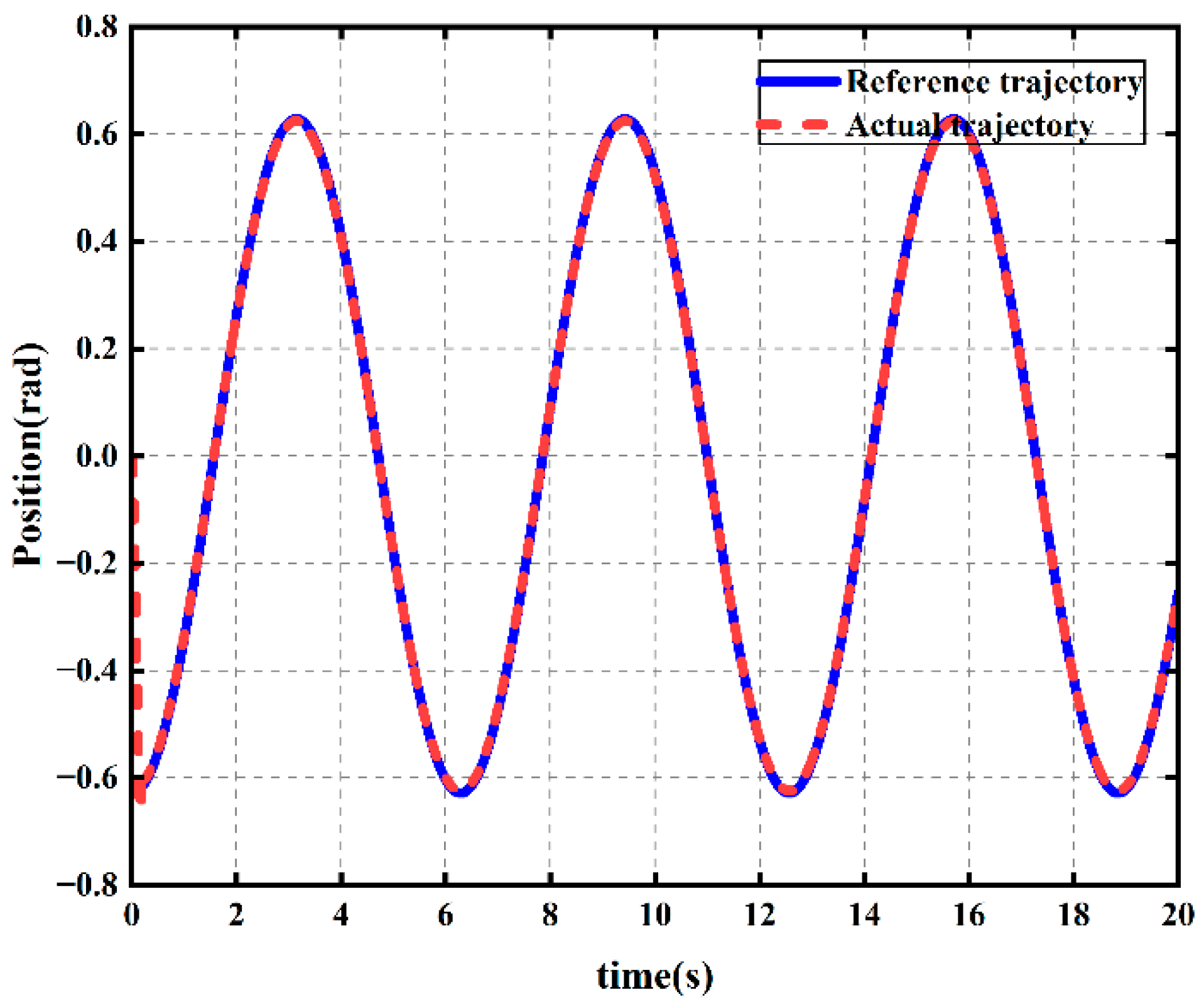
Figure 6 illustrates the position tracking curve of the joint, demonstrating its ability to achieve high-precision tracking of the reference trajectory.
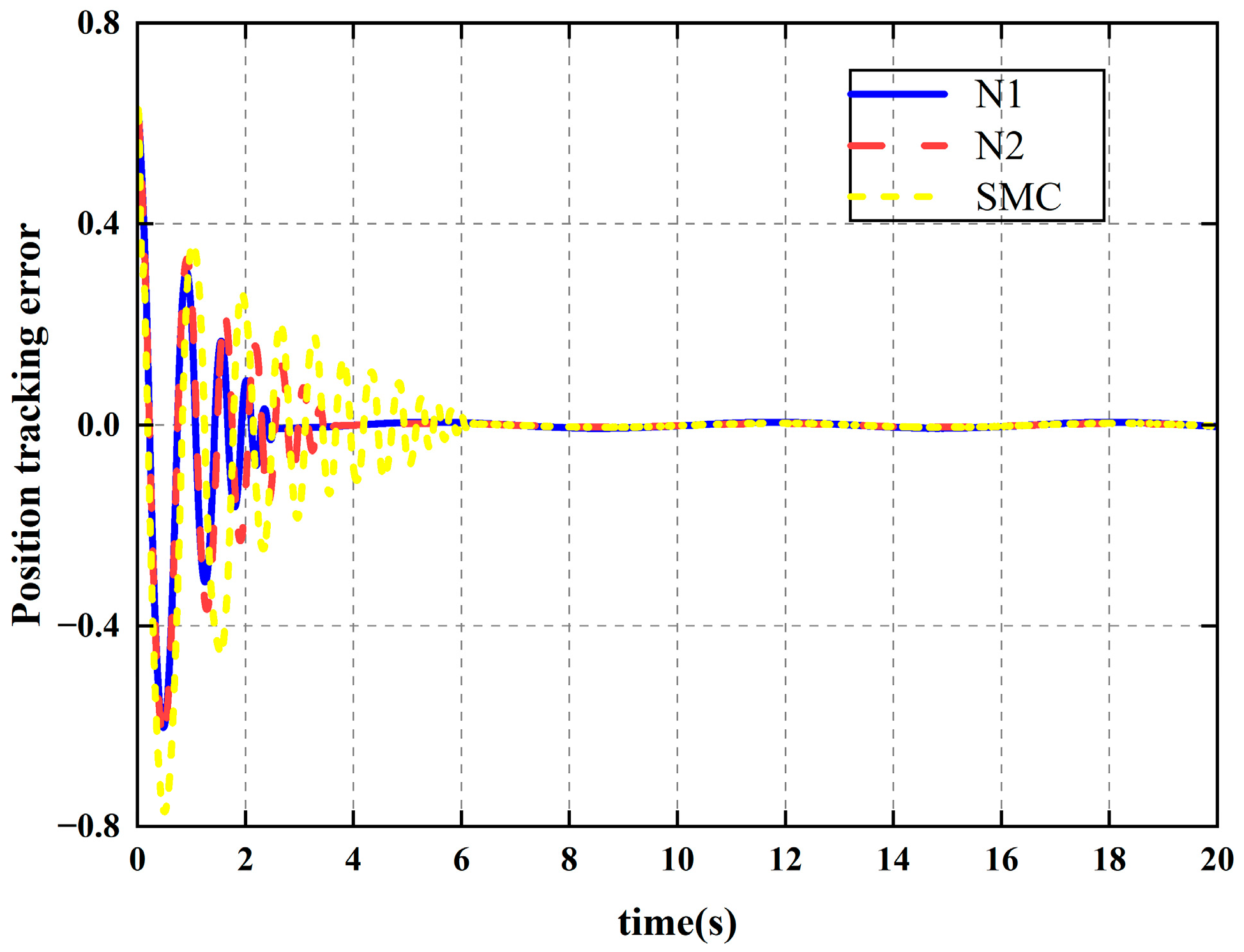
To quantitatively evaluate the RBF neural network’s compensation effect within the control architecture, we implemented three distinct control configurations for comparative analysis. The proposed adaptive controller (N1) integrates RBFNN to achieve real-time approximation and compensation of the system’s nonlinear dynamics under variable loads. To isolate the neural network’s contribution, we developed N2 by removing the RBFNN module from N1 while maintaining identical control gain parameters ( k 1 , k 2 ) and event-triggering thresholds ( μ i , m i ), preserving only the fundamental backstepping control framework. For broader performance benchmarking, we included traditional SMC as a representative robust control method for handling system uncertainties. This experimental design enables precise quantification of the RBFNN’s effectiveness in enhancing trajectory tracking accuracy while demonstrating the relative advantages of the neural network-enhanced approach compared to both simplified adaptive control and conventional methods under variable-load conditions.
Figure 7 presents the joint trajectory tracking error comparison among the three control methods. The results demonstrate that the proposed RBFNN-based controller (N1) achieves the best performance, stabilizing within ±0.05 rad in just 2 s—twice as fast as the non-neural network approach (N2), which requires about 4 s to reach ±0.1 rad accuracy. In contrast, the conventional SMC method shows significantly poorer performance, with steady-state errors fluctuating within ±0.15 rad due to its fixed switching gain and inability to adapt to nonlinear inertial variations under changing loads. The quantitative analysis reveals that N1 reduces the tracking error by 50% compared to N2, and by approximately 67% relative to SMC, clearly demonstrating the superiority of the neural network enhanced control strategy in handling time-varying disturbances. These findings directly address the limitations of traditional SMC highlighted in the introduction section.
Figure 8 displays the control torque of the joint, indicating that the torque remains within a reasonable range.
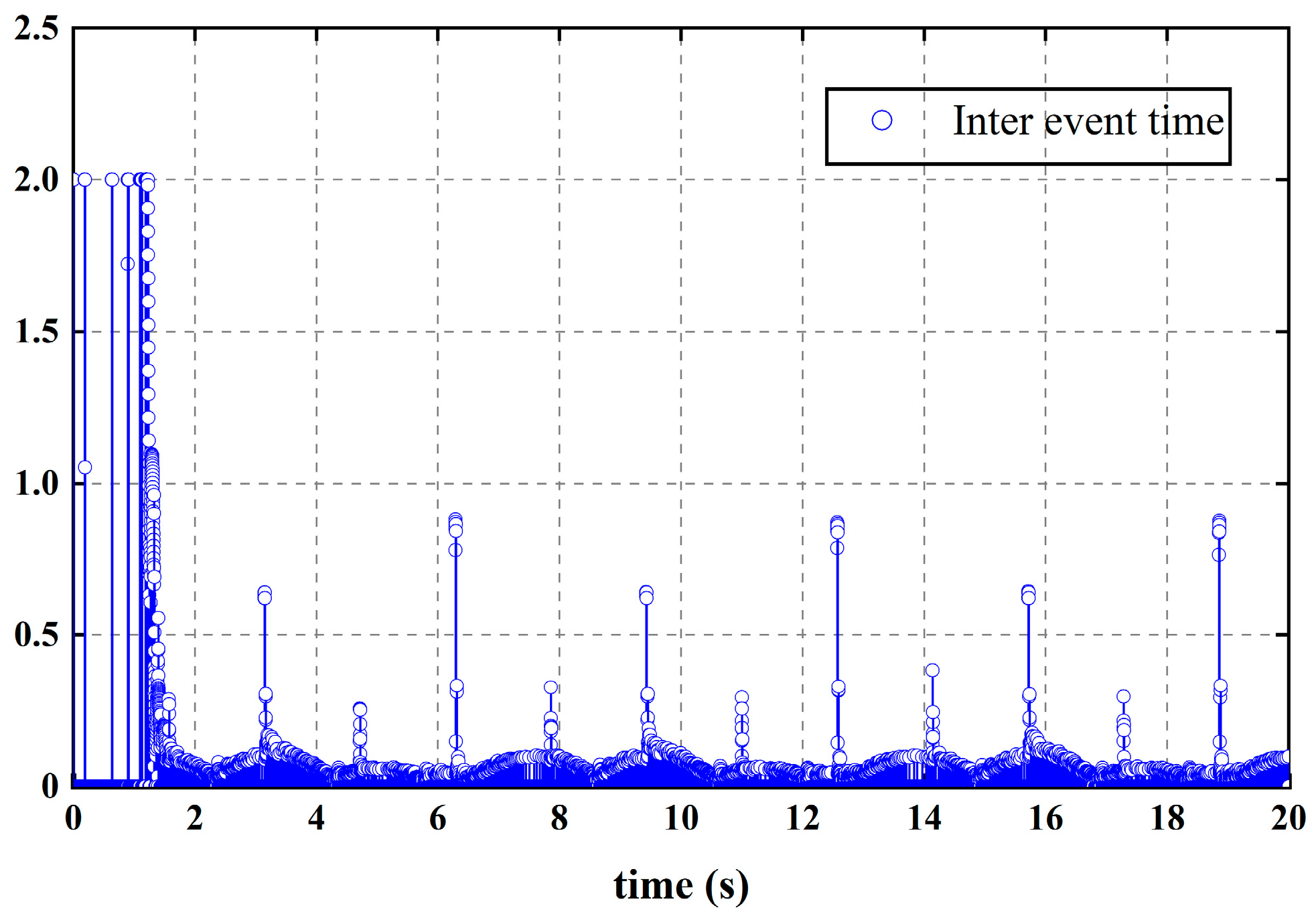
Figure 9 shows the event-triggered interval time for the joint. It demonstrates that the interval between two consecutive controller updates is 0.001 s, confirming the absence of Zeno behavior in the system.
Figure 10 compares the controller update frequency of two control schemes: the proposed neural network event-triggered control and the traditional neural network time-triggered control. The event-triggered mechanism reduces controller updates from 20,000 to 3057 per simulation cycle, achieving an 84.7% reduction. This demonstrates the significant advantage of event-triggered control in minimizing computational load.
To systematically evaluate controller performance, Table 1 presents a comprehensive comparison of three control methods (N1, N2, and SMC) using five key performance metrics for trajectory tracking. The results demonstrate that the RBFNN-based N1 controller achieves optimal performance across all error metrics, showing significantly lower error values than the conventional SMC method while maintaining consistent improvements over the N2 controller.
Particularly noteworthy is the inferior performance of the SMC method in both the integral of time-weighted absolute error (ITAE) and the integral of time-weighted squared error (ITSE). This reveals its more pronounced error accumulation issues during prolonged operation. In contrast, N1′s superior performance in both instantaneous error, measured by root mean square error (RMSE), and steady-state error, measured by integral of absolute error (IAE), validates the effectiveness of the RBFNN compensation mechanism in enhancing tracking accuracy.

6. Discussion and Conclusions

Based on the problem of anti-disturbance trajectory tracking control for multi-joint wafer transfer robot under variable-load conditions, this paper proposes an adaptive control strategy utilizing RBF neural networks. To address parameter uncertainties and nonlinear disturbances induced by load variations, an RBF neural network is employed to approximate the unknown nonlinear functions within the system. An adaptive law is designed to compensate for the effects of load changes in real time. Furthermore, an event-triggered mechanism is introduced to dynamically adjust the control signal update frequency, thereby reducing communication resource consumption, preventing Zeno behavior, and alleviating data transmission overhead. The stability of the closed-loop system is rigorously proven based on Lyapunov theory, and the effectiveness of the proposed method is validated through Simulink simulation experiments. The results demonstrate that the proposed control method N1 significantly outperforms both the N2 and traditional SMC in terms of trajectory tracking accuracy, exhibiting faster error convergence speed and smaller steady-state error. Simultaneously, the event-triggered mechanism effectively reduces the communication burden and prevents redundant data transmission from adversely impacting the system’s real-time performance. This study provides theoretical support and technical references for high-precision anti-disturbance control of wafer transfer robot in complex working conditions.
Regarding the scalability of the proposed control approach, it is important to note that the core principles of the method are not limited to the specific 2-DOF manipulator and 8-inch wafer size considered in this study. The adaptive control strategy, leveraging the RBF neural network’s approximation capabilities and the event-triggered mechanism’s efficient update scheduling, can be extended to manipulators with higher degrees of freedom, such as a 3-DOF manipulator, and to larger wafer dimensions, such as 12-inch wafers. However, increasing the complexity of the system, whether through additional degrees of freedom or larger payloads, would necessitate a more sophisticated dynamic model and potentially more computational resources to maintain the same level of control performance. For instance, a 3-DOF manipulator would introduce more complex interactions between joints, requiring the RBF neural network to approximate a higher-dimensional nonlinear function. Similarly, a larger wafer would result in increased inertia and mass, which could be accommodated by adjusting the neural network parameters and control gains to ensure effective compensation for the enhanced system dynamics. Future work could explore the optimization of the neural network structure and the fine-tuning of control parameters to address these challenges, further expanding the applicability of the proposed approach to a broader range of robotic systems and operating conditions.
Additionally, beyond addressing physical disturbances, the inherent properties of the proposed RBFNN-based adaptive mechanism and event-triggered control warrant investigation for enhancing system security. Recent advances in AI security, e.g., adversarial example defense [36], demonstrate that injecting noise vectors into confidence values can effectively mitigate optimized adversarial attacks in speech recognition systems. Analogously, our online weight-updating RBFNN and event-triggered mechanism, which reduces attack surfaces via sparse communication, could be extended to resist sensor/actuator attacks in robotic control systems. Future work will explore formal integration of these security principles to enhance cyber–physical robustness.
Future work could explore optimization of the neural network structure and experimental validation on hardware platforms to promote its practical application in industrial scenarios.

Author Contributions

Conceptualization, B.X. and L.Y.; methodology, L.Y.; software, L.Y.; validation, L.Y. and H.Y.; formal analysis, L.Y.; investigation, L.Y.; writing—original draft preparation, L.Y.; writing—review and editing, H.Y. and B.X.; supervision, H.Y. and B.X. All authors have read and agreed to the published version of the manuscript.

Funding

This research was funded by the Department of Science and Technology of Hebei Province (grant number 22341802D) and the Changping District Government of Beijing (grant number 202403004015).

Institutional Review Board Statement

Not applicable.

Informed Consent Statement

Not applicable.

Data Availability Statement

The original contributions presented in the study are included in the article. Further inquiries can be directed to the corresponding author.

Acknowledgments

In the process of revising this paper, GenAI was employed as a tool to assist in proofreading and enhancing the grammatical precision of the text. It is important to note that the use of this AI was strictly limited to language refinement. The authors meticulously examined, edited, and approved all suggestions. The final content, analysis, and scholarly contributions remain solely the responsibility of the authors.

Conflicts of Interest

The authors declare no conflicts of interest.

Abbreviations

The following abbreviations are used in this manuscript:
RBFNNRadial Basis Function Neural Network
UUBUniformly Ultimately Bounded
SMCsliding mode control
NNneural networks
ETCevent-triggered control
COMcenter of mass
ITSEintegral of time-weighted squared error
IAEintegral of absolute error
ITAEintegral of time-weighted absolute error
RMSEroot mean square error

Appendix A

In this appendix, we present a sensitivity analysis for the parameters μ i and m i . These parameters are critical in defining the event-triggered condition of the robotic system, thereby affecting the frequency of controller updates.
We adopted a systematic approach for the sensitivity analysis:
Step 1: Individually vary μ i and m i by ±10% from their nominal values, keeping other parameters constant to observe each parameter’s isolated effect.
Step 2: Simultaneously vary μ i and m i to examine their combined impact on the system.
For specific data, refer to Table A1.
Table A1. Sensitivity analysis table.
Parameter VariationNumber of Controller UpdatesChange from Baseline
Baseline3057-
m i − 10%4047+32.4%
m i + 10%3827+25.2%
μ i − 10%3307+8.2%
μ i + 10%3075+0.6%
m i     5 % ,   μ i − 5%4064+32.9%
m i   +   5 % ,   μ i + 5%4990+63.2%
As shown in Table A1, in the sensitivity analysis of the controller, the parameter m i has a significant impact on the number of controller updates. Whether it is increased or decreased, the number of updates increases substantially. In contrast, the parameter μ i has a minimal effect on the update frequency. Thus, in controller design and optimization, it is crucial to focus on selecting m i to reduce update demands. Meanwhile, moderate attention should be given to changes in μ i , especially when it shows a decreasing trend. Additionally, when m i and μ i change simultaneously, particularly when both increase, the demand for controller updates rises significantly. This indicates that the combined variation in parameters can further complicate controller optimization. Therefore, in addition to focusing on the selection of individual parameters like m i , it is essential to be vigilant about the combined changes in parameters, especially the trend of simultaneous increases.

References

  1. Cong, M.; Yu, X.; Shen, B.H.; Liu, J. Research on a Novel R-θ Wafer-Handling Robot. In Proceedings of the IEEE International Conference on Automation and Logistics, Jinan, China, 18–21 August 2007; pp. 597–602. [Google Scholar] [CrossRef]
  2. Liu, Y.; Cao, Y.; Sun, L.; Zheng, X. Accurate and Steady Control on Trajectory Tracking for the Wafer Transfer Robot. Ind. Robot. 2010, 37, 552–561. [Google Scholar] [CrossRef]
  3. Joo, Y.H.; Park, H.; Kim, H.; Choe, R.; Kang, Y.; Jung, J.-Y. Traffic Flow Speed Prediction in Overhead Transport Systems for Semiconductor Fabrication Using Dense-UNet. Processes 2022, 10, 1580. [Google Scholar] [CrossRef]
  4. Jiang, H.; Zhao, Y.; Zhu, L.; Zhang, J.; Liu, C. Review on Vibration Control of Wafer Handling Robot. Intell. Sustain. Manuf. 2025, 2, 10007. [Google Scholar] [CrossRef]
  5. Hu, S.; Liu, H.; Kang, H.; Ouyang, P.; Liu, Z.; Cui, Z. High Precision Hybrid Torque Control for 4-DOF Redundant Parallel Robots under Variable Load. Actuators 2023, 12, 232. [Google Scholar] [CrossRef]
  6. Xiao, B.; Cao, L.; Xu, S.; Liu, L. Robust Tracking Control of Robot Manipulators with Actuator Faults and Joint Velocity Measurement Uncertainty. IEEE/ASME Trans. Mechatron. 2020, 25, 1354–1365. [Google Scholar] [CrossRef]
  7. Thien, R.T.Y.; Kim, Y. Decentralized Formation Flight via PID and Integral Sliding Mode Control. IFAC-PapersOnLine 2018, 51, 13–15. [Google Scholar] [CrossRef]
  8. Nohooji, H.R. Constrained Neural Adaptive PID Control for Robot Manipulators. J. Franklin Inst. 2020, 357, 3907–3923. [Google Scholar] [CrossRef]
  9. Chen, M.; Jiang, B. Robust Attitude Control of Near Space Vehicles with Time-Varying Disturbances. Int. J. Control Autom. Syst. 2013, 11, 182–187. [Google Scholar] [CrossRef]
  10. Awan, S.Z.; Ali, K.; Iqbal, J.; Mehmood, A. Adaptive Backstepping Based Sensor and Actuator Fault Tolerant Control of a Manipulator. J. Electr. Eng. Technol. 2019, 14, 2497–2504. [Google Scholar] [CrossRef]
  11. Omer, S.; Faisal, A.; Jamshed, I. Complex Fractional-Order LQIR for Inverted-Pendulum-Type Robotic Mechanisms: Design and Experimental Validation. Mathematics 2023, 11, 913. [Google Scholar] [CrossRef]
  12. Huynh, V.N.S.; Ngo, H.Q.T.; Nguyen, T.P.; Nguyen, H. High Performance of an Adaptive Sliding Mode Controller under Varying Loads for Lifting-Type Autonomous Grounded Robot. Appl. Sci. 2020, 10, 5858. [Google Scholar] [CrossRef]
  13. Käppler, M.; Mamaev, I.; Alagi, H.; Stein, T.; Deml, B. Optimizing human-robot handovers: The impact of adaptive transport methods. Front. Robot. AI 2023, 10, 1155143. [Google Scholar] [CrossRef] [PubMed]
  14. Ali, K.; Ullah, S.; Mehmood, A.; Mostafa, H.; Marey, M.; Iqbal, J. Adaptive FIT-SMC Approach for an Anthropomorphic Manipulator With Robust Exact Differentiator and Neural Network-Based Friction Compensation. IEEE Access 2022, 10, 3378–3389. [Google Scholar] [CrossRef]
  15. Han, J.; Wang, F.; Sun, C. Trajectory Tracking Control of a Manipulator Based on an Adaptive Neuro-Fuzzy Inference System. Appl. Sci. 2023, 13, 1046. [Google Scholar] [CrossRef]
  16. Zhu, Q.; Sun, W.; Shen, Y.; Fu, G.; Yang, Y.; Li, J. A Novel Combined Control of Flexible Single-Link Manipulator Based on Singularly Perturbed Theory. Robot. Intell. Autom. 2024, 44, 806–816. [Google Scholar] [CrossRef]
  17. Yin, F.; Wen, C.; Ji, Q.; Zhang, H.; Shao, H. A Compensation Sliding Mode Control for Machining Robotic Manipulators Based on Nonlinear Disturbance Observer. Trans. Inst. Meas. Control 2022, 44, 2336–2349. [Google Scholar] [CrossRef]
  18. Saaideh, M.A.; Al-Rawashdeh, Y.M.; Aljanaideh, K.; Zhang, L.; Boker, A.; Janaideh, M.A. Output Feedback Control of Variable-Loaded Four-Joint Manipulators with Unknown Saturated Actuator Dynamics. Int. J. Control Autom. Syst. 2024, 22, 3694–3707. [Google Scholar] [CrossRef]
  19. Shu, X.; Ni, F.; Min, K.; Liu, Y.; Liu, H. A Novel Dual-Arm Adaptive Cooperative Control Framework for Carrying Variable Loads and Active Anti-Overturning. ISA Trans. 2024, 148, 477–489. [Google Scholar] [CrossRef]
  20. Kumar, N. Force/Position Control of Constrained Mobile Manipulators with Fast Terminal Sliding Mode Control and Neural Network. J. Control Autom. Electr. Syst. 2023, 34, 1145–1158. [Google Scholar] [CrossRef]
  21. Rani, S.; Kumar, A.; Kumar, N.; Singh, H.P. Adaptive Robust Motion/Force Control of Constrained Mobile Manipulators Using RBF Neural Network. Int. J. Dyn. Control 2024, 12, 3379–3391. [Google Scholar] [CrossRef]
  22. Gaidhane, P.J.; Nigam, M.J.; Kumar, A.; Pradhan, P.M. Design of Interval Type-2 Fuzzy Precompensated PID Controller Applied to Two-DOF Robotic Manipulator with Variable Payload. ISA Trans. 2019, 89, 169–185. [Google Scholar] [CrossRef]
  23. Zhang, J.; Zheng, Y. Predefined Performance Course Tracking Control of Unmanned Surface Vehicle via the Upper Bounded and Dynamic Event-Triggered Technique. Ocean Eng. 2025, 333, 121532. [Google Scholar] [CrossRef]
  24. Wang, Z.; Qiu, Y.; Hao, Y.; Bai, Y.; Qiu, L.; Zhang, G. Event-Triggered Three-Dimensional Adaptive Anti-Disturbance IGC Method for a Class of Flight Vehicles. Aerosp. Sci. Technol. 2025, 162, 110233. [Google Scholar] [CrossRef]
  25. Li, J.; Fan, Y. Fixed-Time Event-Triggered Fault-Tolerant Formation-Containment Control for Underactuated USVs with Uncertain Dynamics. Nonlinear Dyn. 2025, 113, 21435–21454. [Google Scholar] [CrossRef]
  26. Li, M.; Li, T.; Gao, X.; Shan, Q.; Chen, C.L.P.; Xiao, Y. Adaptive NN Event-Triggered Control for Path Following of Underactuated Vessels with Finite-Time Convergence. Neurocomputing 2019, 379, 203–213. [Google Scholar] [CrossRef]
  27. Fu, L.; An, L. Adaptive Event-Triggered Obstacle Avoidance Control for Unmanned Vehicles via Distance-Velocity Barrier Functions. Inf. Sci. 2025, 702, 121910. [Google Scholar] [CrossRef]
  28. Li, R.; Li, T.; Bai, W.; Du, X. An Adaptive Neural Network Approach for Ship Roll Stabilization via Fin Control. Neurocomputing 2016, 173, 953–957. [Google Scholar] [CrossRef]
  29. Luo, W.; Hu, B.; Li, T. Neural Network Based Fin Control for Ship Roll Stabilization with Guaranteed Robustness. Neurocomputing 2016, 230, 210–218. [Google Scholar] [CrossRef]
  30. Wang, W.; Tong, S. Distributed Adaptive Fuzzy Event-Triggered Containment Control of Nonlinear Strict-Feedback Systems. IEEE Trans. Cybern. 2019, 50, 3973–3983. [Google Scholar] [CrossRef]
  31. Selmic, R.R.; Lewis, F.L. Deadzone Compensation in Motion Control Systems Using Neural Networks. IEEE Trans. Autom. Control 2000, 45, 602–613. [Google Scholar] [CrossRef]
  32. Polycarpou, M.M. Stable Adaptive Neural Control Scheme for Nonlinear Systems. IEEE Trans. Autom. Control 1996, 41, 447–451. [Google Scholar] [CrossRef]
  33. Qiu, X.; Hua, C.; Chen, J.; Zhang, Y.; Guan, X. Event-Triggered Based Adaptive Neural Network Control of a Robotic Manipulator with Output Constraints and Disturbance. Int. J. Syst. Sci. 2021, 52, 2415–2426. [Google Scholar] [CrossRef]
  34. Diao, S.; Sun, W.; Su, S.-F.; Xia, J. Adaptive Fuzzy Event-Triggered Control for Single-Link Flexible-Joint Robots with Actuator Failures. IEEE Trans. Cybern. 2021, 52, 7231–7241. [Google Scholar] [CrossRef] [PubMed]
  35. Slotine, J.J.E.; Li, W.P. Applied Nonlinear Control; China Machine Press: Beijing, China, 1991. [Google Scholar]
  36. Hyun, K. AudioGuard: Speech Recognition System Robust against Optimized Audio Adversarial Examples. Multimed. Tools Appl. 2023, 83, 57943–57962. [Google Scholar] [CrossRef]
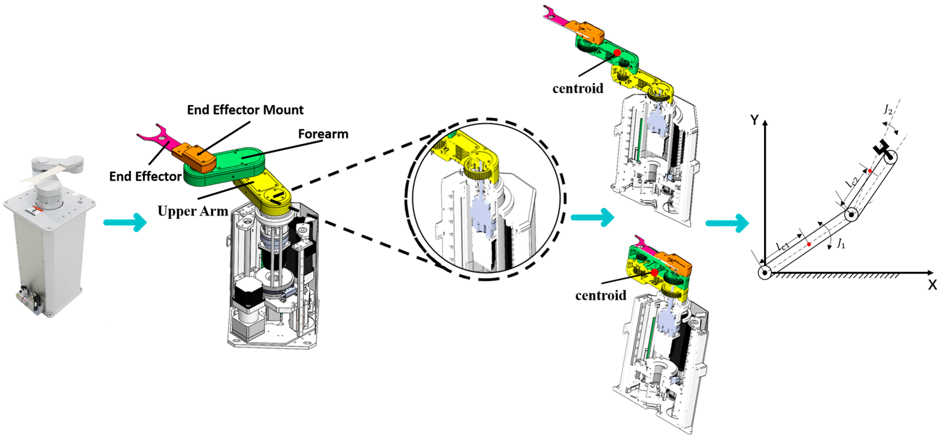
Figure 1. Wafer transfer robot model.
Applsci 15 09193 g001
Figure 2. Variations in joint reaction forces during 6-inch and 8-inch wafer handling.
Applsci 15 09193 g002
Figure 3. Structure of RBFNN.
Applsci 15 09193 g003
Figure 4. Flowchart of the control algorithm.
Applsci 15 09193 g004
Figure 5. Planar 2-DOF manipulator.
Applsci 15 09193 g005
Figure 6. Joint position tracking curve.
Applsci 15 09193 g006
Figure 7. Joint tracking error comparison.
Applsci 15 09193 g007
Figure 8. Joint control input.
Applsci 15 09193 g008
Figure 9. Joint event-triggered interval time.
Applsci 15 09193 g009
Figure 10. Simulation of controller update number.
Applsci 15 09193 g010
Table 1. Quantitative comparison of trajectory tracking error metrics between N1, N2, and SMC.
Performance MetricN1N2SMC
IAE   ( rad s ) 0.56890.67961.0702
ISE   ( rad 2 ) 0.17750.21140.3675
ITAE   ( rad s 2 ) 1.12271.12862.2189
ITSE   ( rad 2 s ) 0.10380.15640.3759
RMSE   ( rad ) 0.09430.10280.1356
Disclaimer/Publisher’s Note: The statements, opinions and data contained in all publications are solely those of the individual author(s) and contributor(s) and not of MDPI and/or the editor(s). MDPI and/or the editor(s) disclaim responsibility for any injury to people or property resulting from any ideas, methods, instructions or products referred to in the content.