Article

Evaluation of the Microstructure and Corrosion Resistance of the 800HT Alloy After Long-Term Operation

Faculty of Materials Engineering and Industrial Computer Science, AGH University of Science and Technology in Krakow, Mickiewicza St. 30, 30-059 Kraków, Poland
*
Author to whom correspondence should be addressed.
Appl. Sci. 2025, 15(16), 9188; https://doi.org/10.3390/app15169188
Submission received: 18 July 2025 / Revised: 14 August 2025 / Accepted: 20 August 2025 / Published: 21 August 2025
(This article belongs to the Section Materials Science and Engineering)

Abstract

The development of renewable fuel-based energy, as well as waste disposal and advanced chemical processes, makes it necessary to use materials with favorable corrosion resistance, especially in high temperature conditions. In such conditions, alloys are subject to degradation, and the rate of the processes depends directly on the state of the material at the beginning of operation and the operating environment conditions. Hence, the 800HT material was selected for the tests, which was subjected to long-term operation in variable ambient conditions. This work aims to reveal the possibility of microstructure recovery in the alloy after long-term operation and subjected to detailed LM and SEM microscopic analysis and corrosion tests in simulated environments. The tests revealed that in long-term operation conditions, periods of temperature exceedance may occur and, as a consequence, unfavorable phases affecting the plasticity of the material, such as σ-phase or M23C6, may be released. In turn, the presence of these phases, mainly at grain boundaries, does not significantly reduce corrosion resistance in nitrogen-rich environments, but causes intensive processes induced by chlorides and sulfates at high temperatures.

1. Introduction

Modern chemical, petrochemical, hydrogen or energy industry installations require a change in the approach to design, which is a consequence of changing operating conditions to increase production efficiency (cost reduction), but also to reduce the impact on the natural environment (pro-ecological activities) [1]. This results in the selection of more advanced materials for construction, often with a complex chemical composition, than typical non-alloy steels or austenitic alloys (e.g., AISI 304/304L or AISI 316/316L) [2,3,4]. On the other hand, changing the operating parameters causes the operating environment to become more aggressive, both in terms of chemistry, temperature and stress [5,6].
Therefore, an important element of the installation operation is also its reliability and limited possibilities of carrying out repairs [2,3,4,5,6,7]. This means that it is important to know not only the new material, but also the material in service, where phase transformations or precipitation processes may occur as a result of temperature, pressure or medium. The consequence is, on the one hand, a reduction in plastic or strength properties, and on the other hand, a deterioration in weldability [8], thus limiting the possibility of carrying out repairs.
Among the materials used in such applications are heat-resistant materials, e.g., ferritic high-chromium steels, nickel alloys, tantalum cobalt alloys, or zirconium alloys.
Incaloy 800HT (X8NiCrAlTi32-21) is an alloy designed for operation at high temperatures in aggressive corrosive environments [9,10,11,12,13]. This means that for many years, it has been successfully used in chemical industry installations, gas power engineering, petrochemical industry and as a material for nuclear reactor components [1,2,3,4,5,6,7,8,9,10,11,12,13]. The use of the material results from the need to ensure failure-free operation for a long period of time [7]. This use, among others, was derived from limited possibilities of carrying out repairs and replacements, where welding joining processes may be impossible to implement. Extreme working conditions often require high metallurgical and microstructural stability of the materials as well as appropriate mechanical properties and corrosion resistance [2,6,11,14,15,16,17]. This means that among such materials, high-chromium ferritic steels, titanium, cobalt, tantalum, zirconium or nickel alloys are used. However, these alloys have their limitations resulting from, for example, the high brittleness of ferritic steels or the very high price of other materials. All these materials are also characterized by limited weldability resulting from metallurgical or technological conditions. Technological limitations result from the welding method, which requires very high metallurgical purity of welded joints and a controlled amount of heat introduced to the material [18]. Welding can be carried out by arc welding, e.g., TIG [19,20,21,22] with the use of an additional material to avoid crystallization cracks, but segregation cracks may appear, or by electron beam, laser or plasma arc. The heat introduced to the material causes a heat-affected zone (HAZ) to be observed outside the weld. The crystallization of the weld causes a coarse-grained structure to be observed in this area [7]. The alloy in delivery conditions has an austenitic structure (γ), which is obtained during solutioning at a temperature of 1200 °C and cooling in warm oil or water. The chemical composition and microstructure provide the alloy with resistance to oxidation up to a temperature of 1100 °C and high creep resistance up to a temperature of 700 °C. The material should not be used in the temperature range between 540 and 760 °C, where intensive precipitation of chromium carbides may occur and, consequently, the alloy brittleness may increase. This indicates that in typical operating conditions, precipitation processes and a decrease in the alloy properties may occur. Gudenko et al. indicate that long-term operation above 800 °C leads to metal embroilment, abrupt grain growth during dynamic recrystallization due to overheating and precipitation of Me23C6 carbides on the grain boundaries [23]. To avoid this, operation at lower temperatures (400–420 °C) is necessary, but welding operations cause degradation of mechanical property characteristics during operations. Effects were also observed in long-term operation of the 800HT alloy in a period of 15 years [24], where the formation of secondary carbides, transformation of primary carbides and formation of G phase (Cr23C6 + Ni16Ti6Si7) were observed. The presence of these phases is main reason for ductility decrease and poor weldability. Refs. [23,24] indicate that increasing strength and hardness and decreasing the toughness during the service can be attributed to microstructural variation. Hence, the article presents the results of tests on the post-operation material, which was subjected to additional thermal loads in the range of limiting temperatures for oxidation resistance and carbide precipitation. During the period of operation, the 800HT alloy pipes were exposed to high temperatures and methane. The tests were to reveal the possibility of restoring the original structure under the operating conditions of the installation and to show the direction of further structural changes under the conditions of long-term operation of the alloy.

2. Materials and Methods

The research was conducted on a post-use section of a pipe with a diameter of 40 mm and a wall thickness of 6.3 mm, which had been used for 25 to 30 years in a methane (CH4) and steam environment at temperatures ranging from 500 °C to 700 °C (with possible periodic overheating and downtime, e.g., during maintenance and repair maintenance breaks). The material grade was initially unspecified due to the period of production of the installation. In order to determine the alloy grade, a study was performed using optical emission spectroscopy (OES) using a Foundry Master-WAS Spectrometer (Hitachi, Tokyo, Japan). The results of the chemical composition study are presented in Table 1. The obtained results indicate that the material meets the requirements for 800HT alloy (1.4959, X8NiCrAlTi32-21). The surface of the pipes showed local surface corrosion defects (Figure 1).
To identify the degree of material degradation, microscopic examinations were performed using light microscopy (LM) and scanning electron microscopy (SEM). Microstructure evaluation was carried out with use of Leica 9i and Leica DM/LM (Leica, Wetzlar, Germany) light microscope and FEI Nova NanoSEM 450 equipped with an energy dispersive X-ray spectrometer (EDS) using EDAX equipment. To perform microscopic observations, samples were cut from pipes using a metallographic cutter with intensive water cooling and then embedded in a thermosetting resin. Samples prepared in this way were subjected to grinding on water-based abrasive paper and polishing on polishing cloth using diamond and corundum suspensions. The samples were observed after electrolytic etching in a 10% aqueous solution of CrO3. Additionally, heat treatment was performed to determine the changes that occurred in the material during use. For this purpose, heat treatment was performed in a tube furnace using an argon as shield gas to avoid the impact of atmospheric air on the surface layer of the material. Pipe sections measuring 40 × 20 × 6.3 mm were processed, which were then cut to make metallographic microsections. The heat treatment program used is included in Table 2. The samples were placed in a heated tube furnace and cooled in air.
In order to determine the changes in mechanical properties, hardness measurements were performed using the Vickers method with an indenter load of 10 kG (HV10) for 10 s (Zwick/Roell ZHU 187.5, Zwick Roell Group, Ulm, Germany).
In order to determine the corrosion potential of alloy, due to surface losses, a corrosion resistance test was performed in relation to identified substances posing a hazard at the place of operation of pipelines, i.e., NaCl, HNO3 and H2SO4. Corrosion tests were performed using the cyclic anodic polarization method in aqueous acid solutions: (1) NaCl at concentrations of 4%, 6% and 8%; (2) HNO3 at concentrations of 2%, 4% and 6%; (3) H2SO4 at concentrations of 2%, 4% and 6%, where the median value is the concentration identified as an operational hazard, using a potentiostat Metrohm Autolab B.V. Based on linear polarization using the Tafel extrapolation method, the corrosion rate of material was extrapolated. The Nova 2.0 software was applied to determine values of corrosion current, corrosion potential, corrosion rate and parameters of equivalent circuit. The tested surface was a clean, metallically polished surface with an area of 1 cm2, and the auxiliary electrode was a platinum electrode.

3. Results

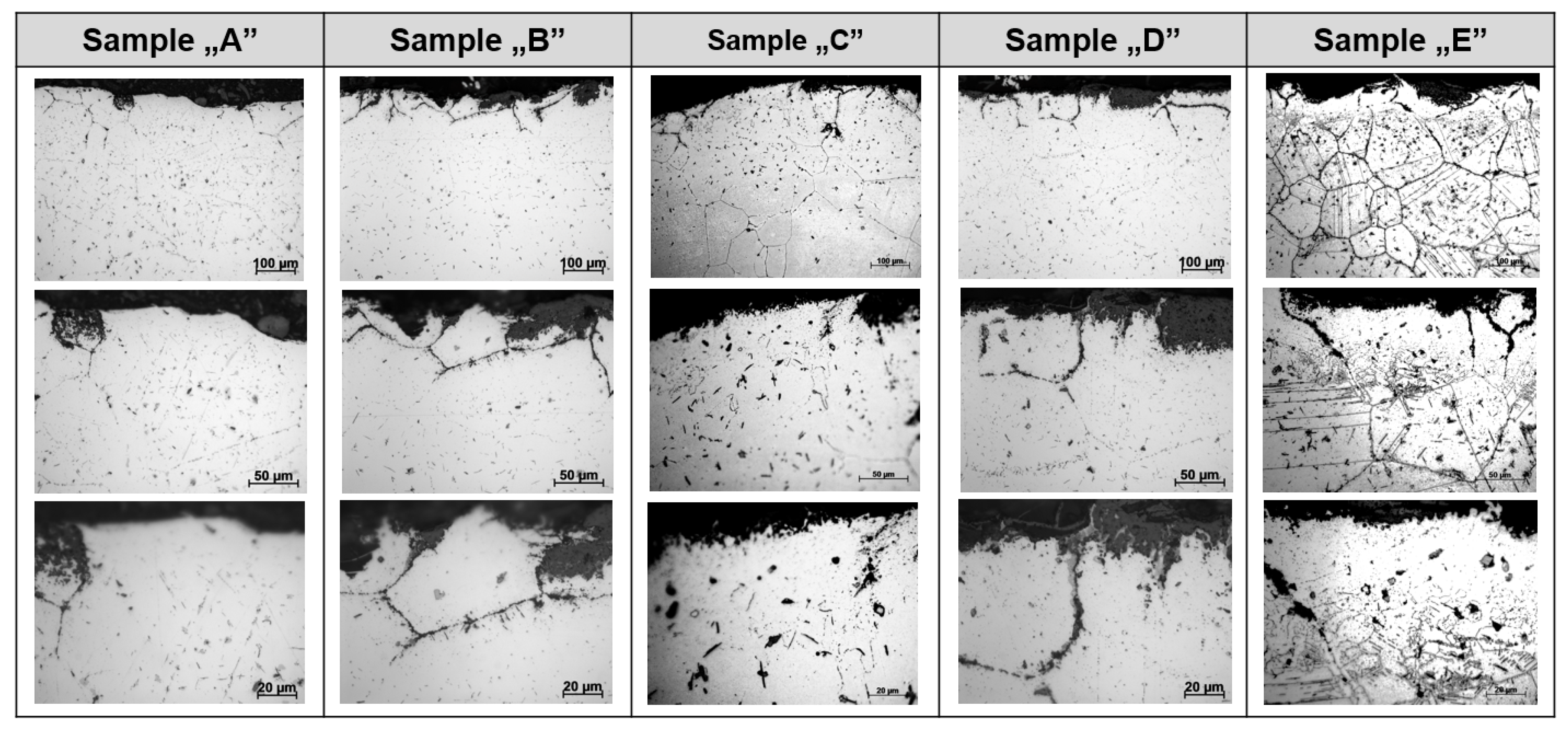
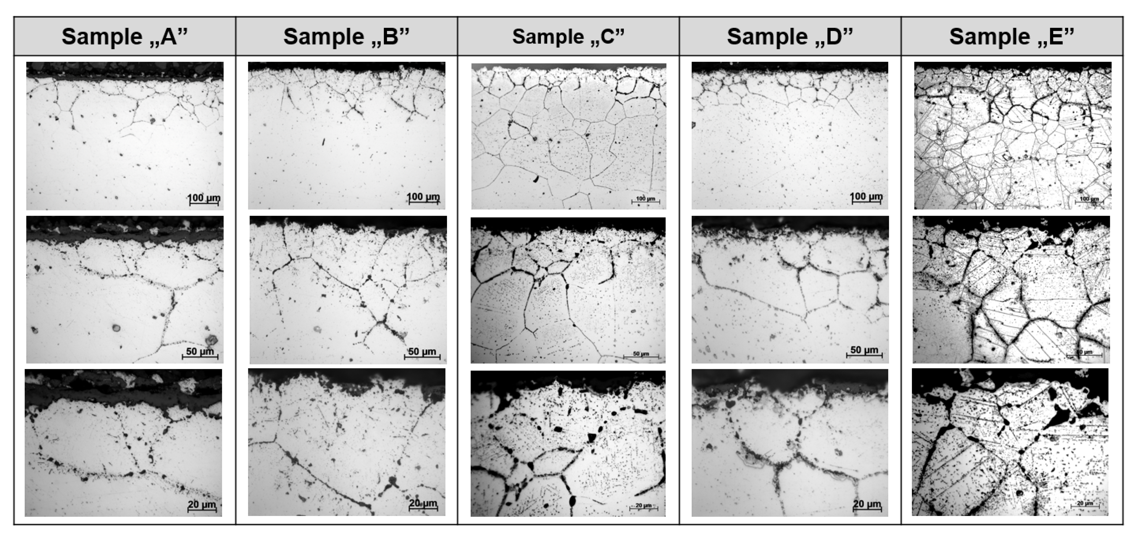
Figure 2 and Figure 3 show the results of microscopic observations using light microscopy. All observed samples show similar morphological features, where clearly outlined grain boundaries with twin boundaries are revealed. The matrix is the γ phase. The material microstructure after operation (Sample A) is characterized by a small number of precipitates evenly distributed throughout the cross-section of the wall. Clearly outlined grain boundaries are observed both from the outside and from the inside. The grain boundary decoration extends to a depth of several grains from the surface. At the outside surface, the structure is characterized by the presence of a large number of plate-like and granular precipitates. The morphology of the precipitates indicates the γ’ phase–Ni(Al,Ti). The presence of this phase indicates that the outside surface was operated at a temperature below 700 °C. Additionally, a small number of σ phase precipitates with regular and acicular shapes were observed. The applied heat treatment at a temperature of 1100 °C (Sample B and C) caused the precipitation of lamellar precipitates at the grain boundaries and their growth with the extension of the annealing time. This indicates that due to the high temperature, limiting for oxidation resistance, but below 1177 °C, the γ’ phase–Ni(Al,Ti) and Cr23C6 and Ti(C,N) precipitates were precipitated [8,9]. The presence of γ’ results from the presence of Ni, Al and Ti in the alloy, but it is not directly visible on the microstructure and is responsible for the secondary strengthening mechanism. Annealing at 1100 °C causes an increase in the number and growth of Cr23C6 and Ti(C,N) precipitates mainly at the grain boundaries, which causes the alloy to strengthen, but in the long term it causes an increase in its brittleness [25].
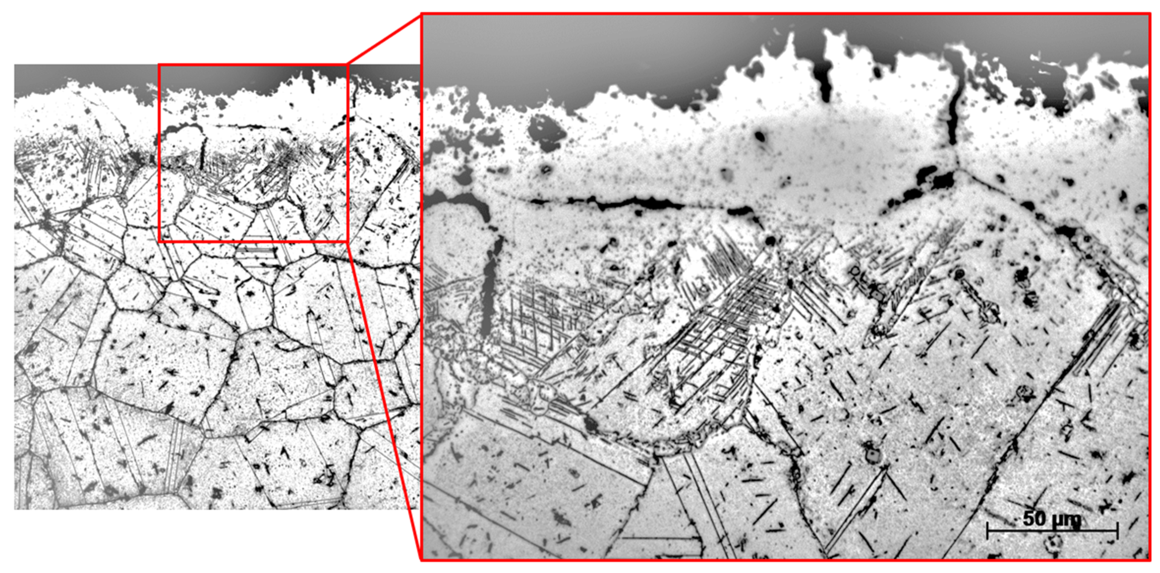
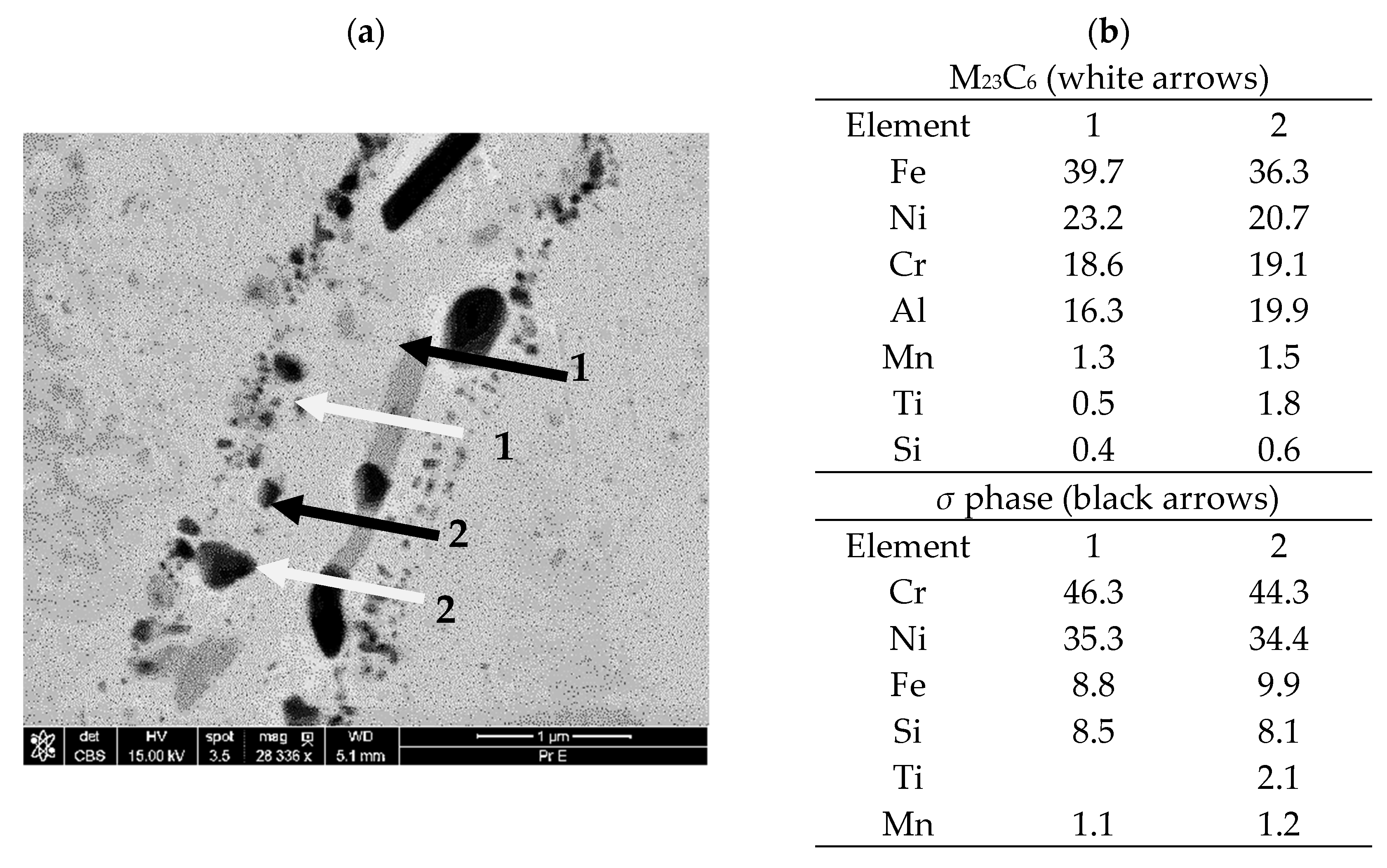
The additional application of annealing at a temperature of 750 °C (Sample D and E) resulted in the intensification of precipitation process inside grains and on grain boundaries not only at the surface but also in the entire wall thickness. The precipitates have the character of plates as well as globular precipitates (Figure 4). This indicates that annealing at a temperature close to the boundary temperature of creep resistance causes intensive processes of precipitation of carbides of the M23C6 or M2C type. Additionally, at this temperature, due to chromium diffusion, the σ phase (FeCr + Mo) can be formed, as shown in Figure 5.
Detailed examinations performed by the SEM method revealed that in the grain boundary areas, there are precipitate characteristic of the σ phase, i.e., the material around these areas is free of precipitates (Figure 5). The shape of the precipitates indicates the coagulation processes taking place. The occurrence of precipitates in plate form indicates the diffusion of chromium to the grain boundaries, which affects the limitation of the plasticity of the grain boundaries. EDX analysis showed that in the structure, there are primary precipitates of Ti(C,N), and particles rich in chromium, which indicates that these are M23C6 carbides. Coagulated precipitates rich in Cr constitute the σ phase, as shown in Figure 5.
HV10 hardness measurements showed that the hardness distribution is uniform across the thickness of the entire cross-section of the material (Figure 6a). A slight increase in the hardness of the samples by about 40HV can be observed at the outer edge of the samples (0.5 mm below outer surface—Figure 6b). This indicates that the pipes were exposed to a significant temperature gradient during operation within the range of safe operation from the inside and in the middle of the wall thickness and within the range of precipitation of carbides and the γ’ and σ phases at the outer surface. Heating at a temperature of 1100 °C did not cause the dissolution of all precipitated phases (Sample B and C on Figure 6a), and additional heating at a temperature of 750 °C caused their increased share (Sample D and E on Figure 6a). This indicates that the main precipitate are M23C6 carbides, and additional phases, including the σ phase, increase their share with the time of holding at a temperature below 750 °C. Therefore, holding pipes at an elevated temperature does not restore the plasticity of the material. The observed increase in surface hardness does not result in the formation of surface cracks, even for sample E. The increase hardness in near-surface region (below 1 mm) with increasing holding time at 750 °C suggests that carbide precipitation will continue, causing further hardness increases. However, at this temperature and with pressure changes within the pipes during operation, surface cracks may initiate and propagate based on fatigue mechanisms or near-surface defects, especially in corrosive environments.
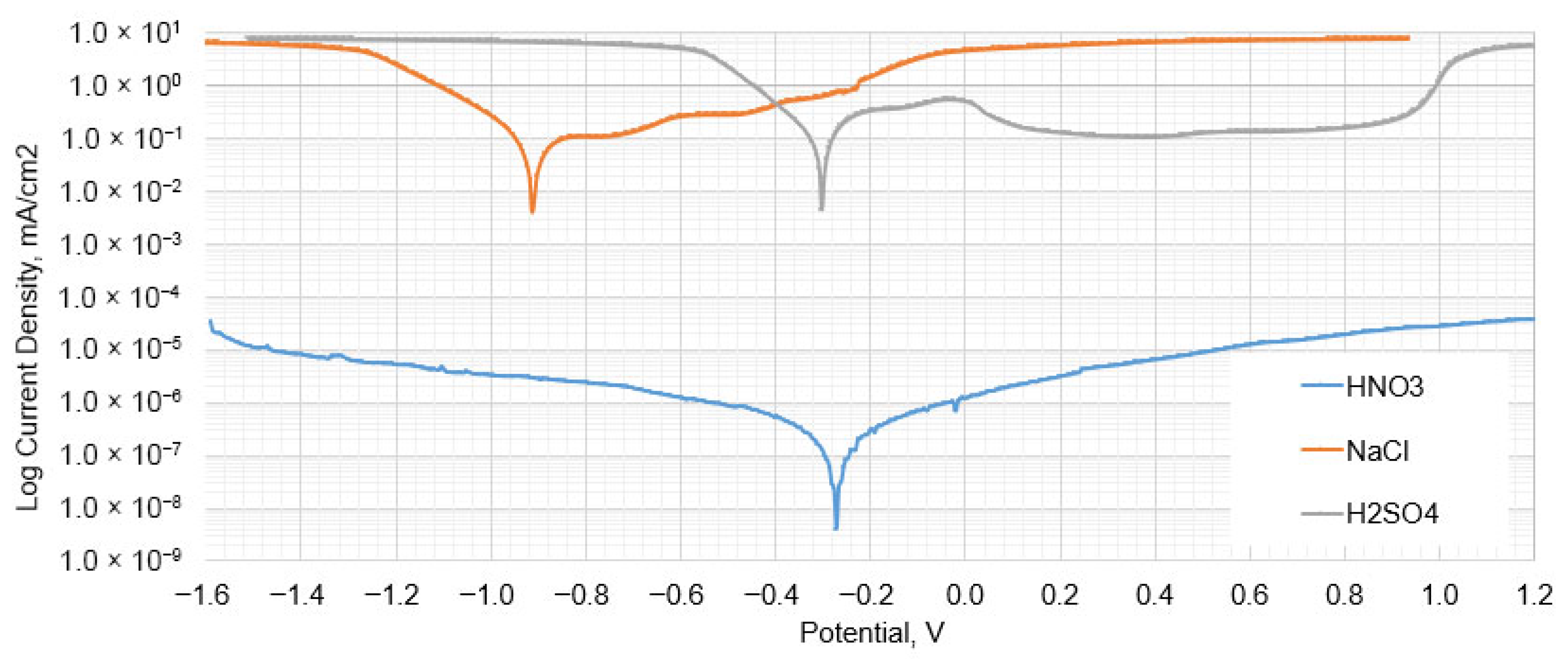
Corrosion tests performed in solutions of different chemical compositions have shown that the potential value changes depending on the type of environment (Table 3). The corrosion potential value ranges between −0.3 V and −0.91 V, providing good corrosion resistance. Corrosion potential values of −303 mV and −272 mV were obtained for H2SO4 and HNO3 respectively, and −910 mV for NaCl. This indicates that an environment rich in chlorides will be more aggressive towards an alloy and there is a greater risk of corrosion pitting. The highest corrosion rate was also recorded for this environment at 9.1 mm/year. The lowest corrosion rates were recorded for HNO3. Changes in the concentration of individual solutions within the tested range did not result in significant changes in corrosion resistance parameters compared to the 4% concentration shown in Figure 7.
The position of the polarization curves for low current density values in the HNO3 and NaCl environment indicates that the 800HT alloy exhibits high properties for maintaining surface passivity, while for H2SO4, continuous dissolution of the material is observed, with a relatively high value of corrosion current obtained (Figure 7). This indicates that the corrosion defects observed on the pipes from the outside are formed mainly during periods of non-operation (technological breaks), when aggressive substances and water (surface moisture) can accumulate on the surface. In normal operation, the external shear temperature shows a temperature of approx. 540–760 °C, i.e., the temperature at which the σ phase can form, but there are no conditions for electrochemical corrosion.

4. Discussion

The tests were performed on post-operation material in the form of a 40 mm diameter and 6.3 mm wall thickness pipe on the surface of which small material losses were identified. The tests of the chemical composition and operating conditions indicate that the pipes were made of the 800HT alloy, where normal operation takes place in the temperature range of 500–740 °C with possible periodic exceedances of temperature up to 1000 °C. This indicates that the 800HT alloy remained unaffected during operation in the range of unfavorable temperatures due to the risk of precipitation of carbides (M23C6, M2C) and intermetallic phase (σ). The tests performed on the post-operation material showed that grain boundaries were decorated with precipitations on the inner side of the pipe and at the outer surface. The presence of an increased number of precipitations mainly covered grain boundaries up to 100 μm from the surface. A consequence of precipitations is an increase in hardness. It also indicates that the plasticity near to the surface of pipe decreased. As a consequence, during further long-term operation, cracking on the pipe surface cracking may begin. It should be assumed that hardness will be a consequence of the heat treatment, including solution heat treatment and soaking time, and will depend on the size of the precipitates. Small, dispersive carbide precipitates dissolve, leading to grain growth and a reduction in hardness (Sample B, Figure 2). Whereas larger amounts of high-temperature precipitates inhibit grain growth, hardening can lead to grain growth (Sample C, Figure 3). Consequently, the hardness reduction compared to the initial state is very slight.
The tested pipes were exposed to long-term high temperature and periodic technological breaks during many years of operation. This indicates that they were subjected to an indefinite number of heating and cooling cycles, where cooling occurred mainly in air. As a result of operation, small local defects appeared on the surface of the pipes, indicating the possibility of pitting corrosion. Corrosion tests in an aggressive environment showed that electrochemical corrosion can occur in the presence of low-concentration acids. The tests carried out in the field of corrosion resistance showed that the main factors causing pitting corrosion of the 800HT alloy are mainly NaCl and H2SO4. In an environment with a high concentration of chlorides, corrosion can reach high speeds of up to 9 mm/year, which indicates that there is a risk of local discontinuities, and sulfuric acid hinders the formation of a passive layer on the surface, causing continuous destruction of the material. The revealed corrosion defects on the external surfaces, despite many years of operation, indicate that they are only superficial in nature, which results from periodic conditions favoring perforation. Nevertheless, considering the corrosion rate in unfavorable (aggressive) environmental conditions, they can cause rapid perforation. This indicates that the use of alloy for pipeline elements requires additional insulation or ensuring the shortest possible periods conducive to the development of corrosion, and the observed surface damage imposes the need for additional inspection activities on the installation.

5. Conclusions

Based on the conducted studies, the following conclusions were drawn:
-
Observations of the microstructure of the tested post-operational samples showed that, as a result of degradation in high temperature conditions, intensive precipitation of σ and γ’ phases and M23C6-type carbides and dispersion phases is observed.
-
The favorable areas for the formation of precipitates are grain boundaries, but their precipitation also occurs inside the grains. The precipitates are initially lamellar in nature, and then, as a result of long-term operation, they grow and take on a spherical shape.
-
Long-term operation did not cause significant changes in hardness that could indicate a decrease in the plasticity of the tested sample.
-
Operating conditions in the high temperature range inhibit electrochemical corrosion processes, but also allow condensates to form on the surface and promote pitting corrosion. The most unfavorable environment is chloride, where the corrosion rate can reach over 9 mm/year at a potential of −0.9 V, and the most favorable is nitric acid, where the loss of thickness is the smallest. The corrosion potential of sulfuric acid and nitric acid is similar.

Author Contributions

Conceptualization, D.S. and L.T.; methodology, L.T., D.S. and S.K.; validation, D.S., L.T. and S.K.; investigation, D.S. and L.T.; writing—original draft preparation, D.S.; writing—review and editing, L.T. and S.K.; funding acquisition, S.K. All authors have read and agreed to the published version of the manuscript.

Funding

This research forms part of Damian Sierkowski’s Industrial PhD Program. Research funding was provided by Ministry of Higher Education, grant number 16.16.110.663. The research project was partly supported by the AGH University through the program “Excellence initiative–research university”.

Institutional Review Board Statement

Not applicable.

Informed Consent Statement

Not applicable.

Data Availability Statement

The original contributions presented in this study are included in the article. Further inquiries can be directed to the corresponding author.

Conflicts of Interest

The authors declare no conflicts of interest.

References

  1. Tapping, R.L.; Lu, Y.C.; Pandey, M.D. Alloy 800 SG tubing: Current Status and future challenges. In Proceedings of the 13th International Conference on Environmental Degradation of Materials in Nuclear Power Systems–Water Reactors, Canadian Nuclear Society (CNS), Whistler, BC, Canada; 2007; pp. 2033–2051. [Google Scholar]
  2. Page, R.A. Small-Angle Neutron Scattering Investigation of Creep Damage in Type 304 Stainless Steel and Alloy 800. Met. Trans. A 1985, 16, 2283–2289. [Google Scholar] [CrossRef]
  3. Tabasov, A.; Krop, J.; Kermes, V.; Nemet, A.; Stehlík, P. Waste-to-energy technologies: Impact on environment. Energy 2012, 44, 146–155. [Google Scholar] [CrossRef]
  4. Mahajan, S.; Chibber, R. Hot corrosion studies of boiler steels exposed to different molten salt mixtures at 950 °C. Eng. Fail. Anal. 2019, 99, 210–224. [Google Scholar] [CrossRef]
  5. Li, Y.S.; Niu, Y.; Wu, W.T. Accelerated corrosion of pure Fe, Ni, Cr and several Fe-based alloys induced by ZnCl2–KCl at 450 °C in oxidizing environment. Mater. Sci. Eng. A 2003, 345, 64–71. [Google Scholar] [CrossRef]
  6. Zhang, K.; Niu, Y.; Zeng, C.; Wu, W. Corrosion of iron and four commercial steels in a Cl-containing oxidizing atmosphere at 500–600 °C. J. Mater. Sci. Technol. 2004, 20, 213–216. [Google Scholar]
  7. Anand, K.; Kumar, S.A.; Tamilmannan, K.; Sathiya, P.; Arivazhagan, B. Metallurgical characterizations and mechanical properties on friction welding of Incoloy 800H joints. J. Mater. Res. 2016, 31, 2173–2185. [Google Scholar] [CrossRef]
  8. Chen, T.; Chen, X.; Liu, C.; Lian, X. Damage analysis of 800 series materials from reformer tube outlet components. Eng. Fail. Anal. 2023, 146, 107134. [Google Scholar] [CrossRef]
  9. Tan, L.; Rakotojaona, L.; Allen, T.R.; Nanstad, R.K.; Busby, J.T. Microstructure optimization of austenitic Alloy 800H (Fe–21Cr–32Ni). Mater. Sci. Eng. A 2011, 528, 2755–2761. [Google Scholar] [CrossRef]
  10. Mirzadeh, H. Constitutive modeling and prediction of hot deformation flow stress under dynamic recrystallization conditions. Mech. Mater. 2015, 85, 66–79. [Google Scholar] [CrossRef]
  11. Xiao, L.; Li, W.; Cota-Sanchez, G. Mechanical property and microstructure characterization of incoloy 800H alloy and its welds after corrosion testing in high temperature steam. Nucl. Eng. Des. 2022, 398, 111970. [Google Scholar] [CrossRef]
  12. Cao, Y.; Di, H.; Zhang, J.; Yang, Y. Dynamic behavior and microstructural evolution during moderate to high strain rate hot deformation of a Fe–Ni–Cr alloy (alloy 800H). J. Nucl. Mater. 2015, 456, 133–141. [Google Scholar] [CrossRef]
  13. Natesan, K.; Shankar, P.S. Uniaxial creep response of Alloy 800H in impure helium and in low oxygen potential environments for nuclear reactor applications. J. Nucl. Mater. 2009, 394, 46–51. [Google Scholar] [CrossRef]
  14. Sun, H.; Liu, J. Hot corrosion of Fe and Ni-based alloys in Wase-to-energy environment at 850 °C. Eng. Fail. Anal. 2022, 133, 105964. [Google Scholar] [CrossRef]
  15. Uusitalo, M.A.; Vuoristo, P.M.J.; Mäntylä, T.A. High temperature corrosion of coatings and boiler steels in reducing chlorine-containing atmosphere. Surf. Coat. Technol. 2002, 161, 275–285. [Google Scholar] [CrossRef]
  16. Goyal, K.; Bhatia, R. Effect of nano yttria stabilized zirconia on corrosion behaviour of chromium oxide coatings on boiler steel. J. Electrochem. Sci. Eng. 2023, 13, 995–1004. [Google Scholar] [CrossRef]
  17. Bankiewicz, D.; Yrjas, P.; Hupa, M. High-Temperature Corrosion of Superheater Tube Materials Exposed to Zinc Salts. Energy Fuels 2009, 23, 3469–3474. [Google Scholar] [CrossRef]
  18. Tuz, L.; Kąc, S.; Sierakowski, D. Technology of electron beam welding of 10CrMo9-10 steel with the specific quality requirements. Manuf. Lett. 2023, 35, 53–57. [Google Scholar] [CrossRef]
  19. Zaghloul, M.B.; Sadek, A.A.; El-Batahgy, A.M.; Hanafy, M. Effect of Welding Parameters on Hot Cracking Susceptibility of Alloy 800. Q. J. Jpn. Weld. Soc. 1994, 12, 335–341. [Google Scholar] [CrossRef]
  20. Bisht, H.; Singh, R.P.; Sharma, V. Study on Welding Parameters in TIG Welding of Incoloy-800: An Investigation with Designed Experiments and ARAS Method; Optimization Methods in Engineering; Springer Nature: New York, NY, USA, 2021; pp. 209–233. [Google Scholar] [CrossRef]
  21. Srirangan, A.K.; Paulraj, S. Multi-response optimization of process parameters for TIG welding of Incoloy 800HT by Taguchi grey relational analysis. Eng. Sci. Technol. Int. J. 2016, 19, 811–817. [Google Scholar] [CrossRef]
  22. Wang, Q.; Sun, D.L.; Na, Y.; Zhou, Y.; Han, X.L.; Wang, J. Effects of TIG welding parameters on morphology and mechanical properties of welded joint of Ni-base superalloy. Procedia Eng. 2011, 10, 37–41. [Google Scholar] [CrossRef]
  23. Gudenko, A.S.; Skorobogatykh, V.N.; Korneev, A.A.; Bardin, I.V.; Parshikova, N.V.; Bukharin, I.I.; Makarova, E.A. Effect of the Operating Temperature of a Steam Methane Reforming Furnace on Structural Changes and Crack Susceptibility in Welding 800HT Nickel Alloy. Metallurgist 2023, 67, 17–24. [Google Scholar] [CrossRef]
  24. Dehmolaei, R.; Shamanian, M.; Kermanpur, A. Microstructural changes and mechanical properties of Incoloy 800 after 15 years service. Mater. Charact. 2009, 60, 246–250. [Google Scholar] [CrossRef]
  25. El-Magd, E.; Nicolini, G.; Farag, M. Effect of Carbide Precipitation in the Creep Behaviour of Alloy 800HT in the Temperature Range 700 °C to 900 °C. Metall. Mater. Trans. A 1996, 27, 747–756. [Google Scholar] [CrossRef]
Figure 1. Outer surface of tested tube with visible surface corrosion defects: (a) general view and (b) macroscopic view.
Applsci 15 09188 g001
Figure 2. Microstructure in the area near the outer wall surface of the tube for heat-treated samples according to Table 2.
Applsci 15 09188 g002
Figure 3. Microstructure in the area near the inner wall surface of the tube for heat-treated samples according to Table 2.
Applsci 15 09188 g003
Figure 4. Sample E microstructure with plate and globular precipitations visible.
Applsci 15 09188 g004
Figure 5. Morphology of M23C6 and σ phase (a) and EDX analysis of precipitations (b); % wt.
Applsci 15 09188 g005
Figure 6. Hardness distribution in the cross-section of the pipe wall (a) and the layout of the measuring points (b).
Applsci 15 09188 g006
Figure 7. Polarization curves for 4% solutions of acids.
Applsci 15 09188 g007
Table 1. Chemical composition of tested material, wt.% and requirements acc. to EN 10088-1:2014-12 for 800HT alloy.
FeCSiMnPSCrNiNAlTiCoCu
Requiredmin. 39.50.05 ÷
0.10
max 0.700max
1.500
max 0.015max 0.01019.0 ÷
22.0
30.0 ÷
34.0
max
0.030
0.25 ÷
0.65
0.25 ÷
0.65
max 0.50max 0.50
Test result45.70.1210.4690.7730.0190.07119.931.5-0.2580.3970.0780.203
Mo ∼ 0.251; Nb ∼ 0.060; V ∼ 0.0704; W ∼ 0.020
Table 2. Heat treatment conditions.
Sample No.SolutioningAnnealing
TemperatureTimeTemperatureTime
Sample A----
Sample B1100 °C1 h--
Sample C1100 °C10 h--
Sample D1100 °C10 h750 °C24 h
Sample E1100 °C10 h750 °C72 h
Table 3. Corrosion parameters for 800HT alloy in 4% water solutions of acids.
ParameterUnitH2SO4HNO3NaCl
Corrosion potentialECORRmV−302.81−272.48−910.57
Corrosion currentjCORRμA/cm2111.798.50 × 10−4395.75
Corrosion rateCRmm/year2.5761.96 × 10−59.1192
Tafel anodic constantβaV/dec0.13741.1549−0.98375
Tafel cathodic constantβcV/dec0.150780.856650.28637
Polarization resistanceRpΩ279.292.51 × 108443.31
Disclaimer/Publisher’s Note: The statements, opinions and data contained in all publications are solely those of the individual author(s) and contributor(s) and not of MDPI and/or the editor(s). MDPI and/or the editor(s) disclaim responsibility for any injury to people or property resulting from any ideas, methods, instructions or products referred to in the content.