Article

Design of Forward Osmosis Desalination Configurations: Exergy and Energy Perspectives

Department of Mechanical Engineering, Sogang University, Seoul 04107, Republic of Korea
*
Author to whom correspondence should be addressed.
Appl. Sci. 2025, 15(16), 9168; https://doi.org/10.3390/app15169168
Submission received: 28 May 2025 / Revised: 13 August 2025 / Accepted: 19 August 2025 / Published: 20 August 2025

Abstract

This study presents a detailed energy and exergy analysis of two forward osmosis (FO) desalination systems: single-pass and regenerative configurations. Both utilize osmotic pressure from a concentrated draw solution to drive water transport through a semi-permeable membrane. The regenerative system includes extra components for draw solute recovery, which increases electrical energy consumption to 188.9 kW and slightly lowers water recovery to 54%, compared to 98 kW and 60% for the single-pass FO system. Equivalent work for desalination is 1.4 kWh/m3 for single-pass and 1.8 kWh/m3 for regenerative FO systems. Exergy analysis shows the distillation column as the largest contributor to exergy destruction in both systems, responsible for over 44% of losses. The regenerative system adds 57.9 MW of chemical exergy destruction in the regenerator. Physical exergy destruction mainly occurs in the reboiler and condenser, while chemical exergy destruction is dominant in the FO membrane unit and regenerator. These findings provide valuable insights for improving the efficiency and sustainability of FO desalination technologies.

1. Introduction

Population growth, rapid urbanization, rising living standards, and industrial expansion are driving a significant increase in water demand across domestic and industrial sectors [1]. With global population expected to reach between 9.4 and 10.2 billion by 2050, projections indicate that over half of the world’s countries will face water scarcity [2,3]. Concurrently, energy shortages pose a growing and interrelated challenge, with consequences for both economic development and environmental sustainability. The global power generation capacity, currently estimated at 7073 GW, is projected to increase to 10,394 GW by 2030 and 12,656 GW in subsequent years [4]. The water–energy nexus—a framework describing the mutual dependence of water and energy resources—underscores the complexity of addressing these critical global challenges [5,6]. Seawater desalination and wastewater treatment have emerged as key technological solutions [7]. Desalination, in particular, offers a promising approach to alleviate freshwater shortages. Currently, around 21,000 desalination facilities worldwide produce approximately 0.12 billion m3 of potable water per day [8,9,10].
All desalination technologies are based on core chemical engineering principles, utilizing thermal, mechanical, or electrical energy to remove salts from saline water. The process generates two streams, desalinated freshwater and concentrated brine, which require environmentally responsible disposal. Desalination processes are broadly categorized into thermal and membrane-based technologies based on their separation mechanisms. Thermal processes operate via evaporation and condensation, while membrane technologies rely on semi-permeable membranes to selectively separate salts from water [11]. Thermal desalination is among the earliest and most established methods for producing freshwater from seawater or brackish sources. It typically involves heating saline water to generate vapor, which is then condensed to produce freshwater. Widely used thermal processes include multi-stage flash (MSF), multi-effect distillation (MED), and vapor compression (VC). Among these, MSF remains the most extensively deployed method, using multiple stages of heat exchange to progressively evaporate and condense water [12]. Membrane-based desalination functions based on either pressure-driven or electrically driven separation mechanisms [13]. Pressure-driven membrane processes are typically classified into four categories: reverse osmosis (RO), nanofiltration (NF), ultrafiltration (UF), and microfiltration (MF). RO, in particular, has demonstrated high efficacy in salt removal and is the most widely adopted membrane technology for seawater desalination while NF also contributes to a certain extent [14]. The process involves applying pressure greater than the osmotic pressure of the feedwater to drive water molecules across a semi-permeable membrane while retaining the majority of dissolved salts. Advances in membrane materials and process engineering have significantly improved operational efficiency and reduced the cost of large-scale RO systems [5,15,16,17,18,19]. Notably, reverse osmosis has seen significant technological advancements, resulting in reduced energy consumption and operational expenses. RO is now widely regarded as one of the most energy-efficient methods to both seawater desalination and advanced water reuse. Despite these advancements, RO desalination continues to face several technical and economic barriers. Chief among these is the high specific energy consumption associated with treating seawater and brackish water [20,21,22]. Furthermore, the disposal of hypersaline brine presents substantial environmental challenges due to its potential ecological impact [23], and the high cost and limited lifespan of RO membranes contribute to long-term operational expenses [24].
In response to these limitations, research has increasingly focused on emerging technologies such as forward osmosis (FO), which offers the potential for reduced energy consumption and environmental impact. FO has attracted considerable academic interest over the past decade, as evidenced by a growing body of literature [21]. Compared to RO, FO presents several notable advantages. First, water transport is driven by the natural osmotic pressure difference, eliminating the need for the high pressures required in RO. As a result, FO requires fewer high-pressure components and exhibits substantially lower energy consumption. Second, the absence of high-pressure operation reduces mechanical stress on the membranes, thereby extending their operational lifespan. Third, whereas RO performance is hindered when the concentration difference between feedwater and permeate is too large, due to the associated increase in osmotic pressure, FO can process high-salinity brines and wastewater effectively, as it utilizes rather than overcomes the osmotic pressure gradient. This membrane-based process utilizes the osmotic pressure gradient to induce water diffusion from a lower-concentration feed solution to a higher-concentration draw solution across a semi-permeable membrane [25,26,27]. A critical factor in FO system design is the selection of an appropriate draw solution and the development of an efficient recovery method for separating purified water from the diluted draw solution. Studies have identified ammonium bicarbonate as a promising candidate for draw solute recovery due to its suitability for thermal separation [28]. While alternative draw solutes have been proposed [29], ammonium bicarbonate remains a strong contender for continuous FO desalination systems [30]. However, for FO to be viable as a sustainable desalination solution, it must be integrated with an effective secondary separation process.
To evaluate these configurations, both traditional energy analysis and exergy analysis were employed. Most studies on desalination systems have focused on improving thermodynamic efficiency and proposing changes to increase performance [5,15,16,17,18,19]. While energy analysis provides an overview of energy input and output, it often lacks the resolution required to identify inefficiencies within individual components. Exergy analysis offers a more comprehensive thermodynamic perspective by accounting for both the quantity and quality of energy transformations. For example, in a steam power plant, energy analysis may assess overall thermal efficiency, whereas exergy analysis quantifies losses in specific components such as boilers, turbines, and condensers due to irreversibilities like heat transfer across finite temperature differences or mechanical friction [31]. This deeper insight facilitates targeted system optimization strategies, such as enhancing heat exchanger performance or reducing entropy generation through improved component design and insulation. Consequently, exergy analysis serves as both a diagnostic and strategic tool for advancing the design, operation, and sustainability of energy-intensive systems such as desalination plants [32,33,34,35,36]. Despite these advances, the exergy performance of FO systems remains less explored compared to conventional desalination technologies such as RO and MSF distillation. Key challenges include accurately modeling the osmotic work contribution, quantifying losses in draw solution recovery processes, and integrating thermal and mechanical components into a unified exergy framework. Addressing these gaps is essential to provide reliable design guidelines, improve system-level efficiency, and facilitate the implementation of FO as a sustainable alternative in large-scale water treatment and desalination [37,38,39,40].
In this study, two FO desalination configurations are proposed. The first is a single-pass FO system integrated with a distillation-based separation process, intended to assess the performance of core components. However, without solute recovery, this configuration is economically unsustainable for real-world applications. Therefore, a second, regenerative FO system incorporating solute reuse is also proposed to support continuous operation and practical implementation.

2. Materials and Methods

2.1. Forward Osmosis Desalination System Design

The membrane utilized in the FO process is functionally analogous to that used in RO, permitting the selective passage of water while effectively rejecting dissolved solutes. However, the fundamental distinction between these two membrane-based technologies lies in their respective driving forces. While RO operates under externally applied hydraulic pressure, the FO process is driven by an osmotic pressure gradient. To induce water flux across the membrane, the osmotic pressure of the draw solution must exceed that of the feed solution. In this study, ammonium bicarbonate is employed as the draw solute to establish the required osmotic potential.
Figure 1 illustrates the schematic configurations of the FO desalination systems examined. As shown in Figure 1a, the single-pass FO system comprises three primary sections: (i) a pre-treatment unit equipped with an intake pump; (ii) an FO membrane unit; and (iii) a post-treatment subsystem, which includes a distillation column, condenser, and reboiler. In this configuration, the osmotic pressure gradient between the draw and feed solutions drives water transport across a semi-permeable membrane, resulting in the dilution of the draw solution. Following the FO process, the diluted draw solution undergoes thermal decomposition to recover the solute. This is achieved through the thermal dissociation of ammonium bicarbonate and related compounds—namely carbonate and carbamate salts—into ammonia and carbon dioxide gases under controlled temperature and pressure conditions [41,42]. At atmospheric pressure, ammonium bicarbonate decomposes at approximately 60 °C, with the decomposition temperature decreasing under reduced pressure. Among various solute recovery methods, vacuum distillation has been identified as the most energy-efficient technique. In this setup, the reboiler heats the solution to temperatures as low as 45 °C, generating water vapor that ascends through the distillation column, while the diluted draw solution flows downward in a counter-current configuration. Heat exchange between the ascending vapor and descending liquid facilitates the fractional separation of volatile and non-volatile components. Volatile species such as ammonia and carbon dioxide concentrate in the upper section of the column, while the less volatile water accumulates at the base. Under steady-state operation, the water product collected at the bottom of the column contains less than 1 ppm of ammonia and carbon dioxide, ensuring high water purity.
In the single-pass FO configuration, the diluted draw solution is ultimately separated into two output streams: regenerated draw solution and freshwater. However, this mode of operation incurs a loss of draw solutes during each cycle, rendering it impractical for long-term operation without solute recovery. To address this, a regenerative FO configuration, shown in Figure 1b, is proposed to enable continuous solute reuse. The regenerative system incorporates a dedicated solute recovery loop, which includes a regenerator unit and auxiliary components such as a heat exchanger and circulation pump. The circulation pump transports hot coolant—recovered from the distillation column and maintained at approximately 35 °C—to facilitate the regeneration process. The diluted draw solution exiting the FO membrane unit is recycled and reused, thereby closing the solute loop and enabling sustained operation.
To simulate the performance of the two configurations, a cellulose acetate FO membrane was employed. The membrane exhibits a water permeability of 4.33 × 10⁻¹² m·s−1·Pa−1 and a salt permeability of 6.66 × 10⁻⁸ m·s−1. The feed solution, modeled as an ideal binary mixture of liquid water and sodium chloride, enters the FO unit at a mass flow rate of 166 kg/s. The draw solution is introduced at a flow rate of 155 kg/s. Both streams are maintained at an inlet temperature of 25 °C. All process simulations were performed using the ELECNRTL property method in Aspen Plus V14.5, which provides accurate thermodynamic data, including enthalpy and entropy, for each process stream.

2.2. Exergy Analysis Methodology

Exergy represents the maximum theoretical work that can be extracted from a system as it comes into equilibrium with its environment, referred to as the dead state. At this state—typically defined by standard atmospheric pressure (1 atm) and ambient temperature (25 °C)—the exergy of the system is zero [43]. Exergy encompasses four main components: physical, chemical, kinetic, and potential exergy [44]. In this study, kinetic and potential contributions are assumed negligible, focusing the analysis on physical and chemical exergy components. Exergy analysis serves as a diagnostic tool for identifying the location, magnitude, and origin of thermodynamic irreversibilities and inefficiencies within system components [45].
The following assumptions underpin the exergy analysis conducted:
  • The system operates under steady-state conditions;
  • Kinetic and potential contributions are neglected [46];
  • Thermophysical properties of water and seawater are estimated using the correlations developed by Sharqawy et al. [43,47];
  • Pump work is assumed to be supplied by electrical energy.
The total specific exergy of a stream is expressed as the sum of its physical and chemical components.
e x t o t = e x p h + e x c h
The physical exergy of water and solution streams can be calculated by [48]. Physical exergy refers to the portion of total exergy that is associated with temperature and pressure of the system’s reactants and products. It is quantitatively expressed based on the deviation of enthalpy and entropy from standard reference conditions, typically taken as T0 = 298 K and P0 = 1 atm. The general expression for physical specific exergy is given by
e x p h = h h 0 T 0 s s 0
where h and s denote the specific enthalpy entropy of the stream, respectively, and h0 and s0 are values at the reference state.
Chemical exergy represents the maximum work attainable as the chemical composition of a solution shifts to equilibrium with its surroundings under reference conditions of temperature (T0) and pressure (P0) [43]. This exergy is derived from the difference in chemical potential (μ), which is typically evaluated using the relationships between the practical osmotic coefficient (φ) of the solvent and the mean activity coefficient (γ) of the solute [44].
e x c h = w s i = 1 n μ i + μ 0 i ˙
where the superscript ‘i’ denotes each individual component within the solution stream.
The exergy balance for each system component is governed by the following general relation:
E ˙ x in   = E ˙ x out + E ˙ x d + E ˙ x loss
The exergy output rate E ˙ x out   denotes the useful output or desired outcome produced by a given unit process. In contrast, the input exergy rate E ˙ x input   reflects total exergy resources consumed to produce this output. The discrepancy between input and output exergy is primarily attributed to the exergy destruction rate within the system E ˙ x d and the rate of exergy losses to the surroundings E ˙ x loss   .
The exergy destruction rate within the system arises from both physical and chemical contributions:
E ˙ x d = E ˙ x ph , d + E ˙ x c h , d
The physical exergy destruction rate of each stream can be obtained by
E ˙ x p h , d i = m ˙ in e x p h , in ( m ˙ i n m ˙ v ) e x ph , out
where m ˙ in denotes the mass flow rate of the stream entering the membrane, m ˙ v represents the mass flow rate of the vapor produced, e x p h , in is the specific exergy at the membrane inlet, and e x ph , out is the specific exergy at the membrane outlet, respectively.
Accordingly, the total physical exergy destruction rate is calculated by adding the physical exergy destruction rates of various streams.
E ˙ x ph , d = i = 1 n E ˙ x p h , d i ˙
The chemical exergy destruction rate of the solution stream can be expressed as
E ˙ x c h , d   = m ˙ ( e x ch , in e x ch , out )
where m ˙ represents the mass flow rate of the solution, and e x ch , in   and e x ch , out are the chemical exergies at the inlet and outlet, respectively.

3. Results and Discussion

3.1. Energy Analysis of FO Desalination Systems

Thermal and electrical energy requirements for the single-pass FO system are summarized in Table 1. A total of 114.5 MW of thermal energy is consumed by the distillation column, and 98 kW of electrical energy is used to operate auxiliary components such as the intake pump for the feed solution. Since the FO system operates at low pressure, the energy requirement for pumping is relatively low. The single-pass FO system achieves a salt rejection rate of 98% and a water recovery rate of 60%. Reported bench-scale [49] and pilot-scale [50,51] studies have shown a maximum FO recovery of approximately 55%. To compare the performance of work-driven desalination systems, specific energy consumption (SEC) is commonly used. SEC represents the amount of electrical energy required to produce one cubic meter of freshwater. In conventional desalination technologies such as MSF and MED, SEC values typically range from 13 to 22 kWh/m3 [52], while RO processes generally consume 3.8–4.5 kWh/m3 [53]. In contrast, FO processes exhibit much lower SEC values, typically in the range of 0.09–0.55 kWh/m3 [50,51,54]. This is primarily because, unlike other processes, electrical energy in FO is mainly consumed for circulating the feed and draw solutions. For a more accurate evaluation of FO system energy consumption, it is recommended to use the concept of equivalent work rather than SEC alone [41]. As a result, the equivalent work required for desalination in the single-pass FO system is calculated to be 1.4 kWh/m3.
Table 1 also presents data for the regenerative FO system. The heat duty and salt rejection rate remain the same as those in the single-pass FO system, 114.5 MW and 98%, respectively, because the main distillation components (FO membrane unit, distillation column, condenser, and reboiler) are shared between the two configurations. The distinction lies in the post-desalination components responsible for draw solute reuse, such as the circulation pump, heat exchanger, and regenerator. Due to the additional equipment required for draw solute regeneration, electrical energy consumption increases to 188.9 kW in the regenerative FO system. Although the salt rejection rate of the FO membrane unit remains unchanged, the overall system recovery rate decreases to 54% because a portion of the product water is utilized for draw solution regeneration. This increase in electrical energy consumption and the reduction in water recovery rate contribute to a slightly higher equivalent work of 1.8 kWh/m3 for the regenerative FO system.

3.2. Component-Wise Exergy Analysis of FO Desalination Systems by Components

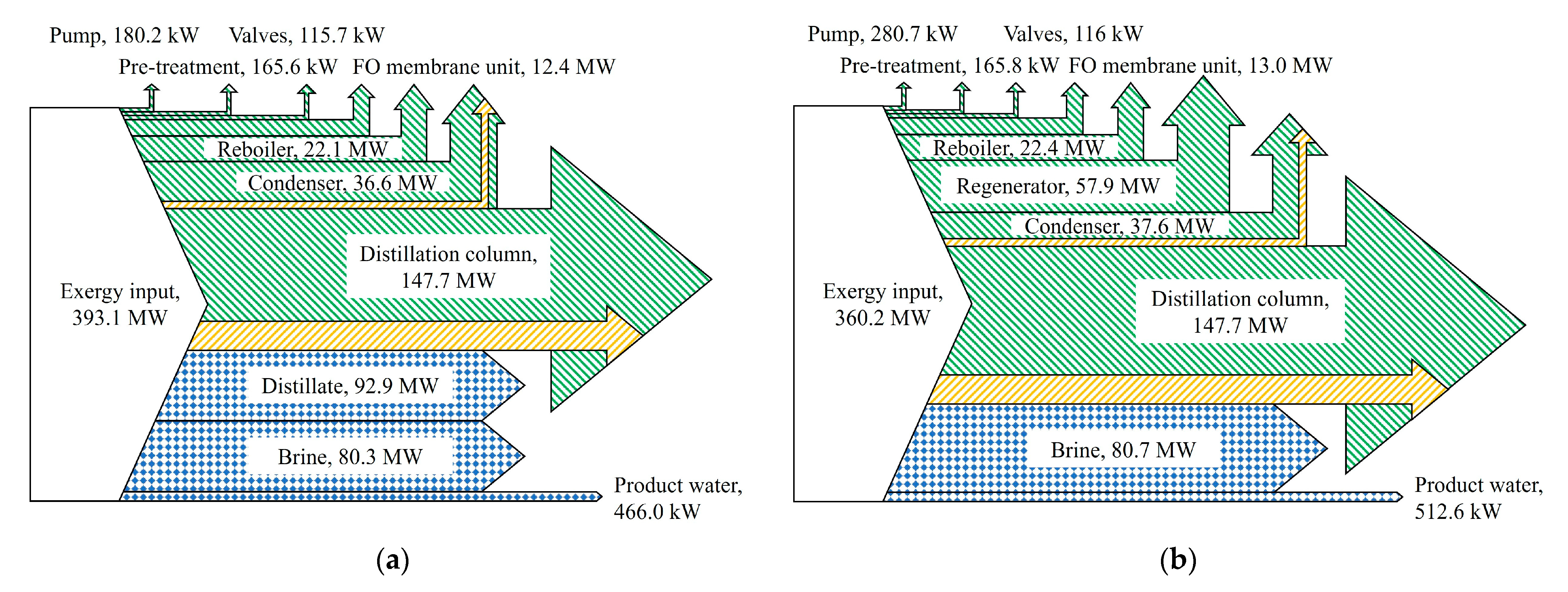
Exergy analysis was conducted for the two proposed FO system configurations. Exergy values of each component were calculated by compiling the incoming and outgoing streams associated with that component. The resulting exergy flows are illustrated in Figure 2, where material discharges from the system are indicated in blue, while exergy destruction and exergy loss are represented in green and orange, respectively. In Figure 2a, exergy distribution of the single-pass FO system is presented. Total exergy input, amounting to 393.1 MW, includes the feed solution, draw solution, thermal energy (heat duty), and electricity. As the process progresses through the system, this input exergy is either destroyed within components, lost to the environment, or emitted as product output. The distillation column accounts for the largest share of exergy destruction and loss, with 147.7 MW of exergy destruction including exergy loss. Other significant sources of exergy reduction include the condenser (36.6 MW), reboiler (22.1 MW), and FO membrane unit (12.4 MW). Exergy loss to the surroundings occurs primarily in the distillation column (24.7 MW) and condenser (1.3 MW). The distillate is expelled with high exergy of 92.9 MW, as no solute recovery process exists in the single-pass FO system. The brine stream also exits the system with high exergy, 80.3 MW, due to increased concentration and thus higher chemical potential following the desalination process. The product water is discharged with 466.0 kW of exergy, which is attributed to its elevated temperature relative to the reference state after passing through the reboiler.
Exergy flow for the regenerative FO system is shown in Figure 2b. As discussed in Section 3.1, the components directly involved in the desalination process, which are the pumps, pre-treatment unit, FO membrane unit, distillation column, condenser, and reboiler, exhibit a similar trend to those in the single-pass FO system. However, due to the additional requirement of solute regeneration, the circulation pump introduces increased exergy destruction in the pumping system. Total exergy input in the regenerative FO system is 360.2 MW, which includes the additional draw solute required to compensate for any deficit during the regeneration process. The reduction in input exergy in the regenerative FO system is primarily attributed to the reuse of the draw solute. In the single-pass FO system, the entire draw solute is discarded and replenished in each cycle due to the absence of a recovery process. Conversely, the regenerative FO system incorporates a solute reuse mechanism, necessitating only the supplementation of the solute to offset losses.
Exergy reductions observed in the condenser (37.6 MW), reboiler (22.4 MW), and FO membrane unit (13.0 MW) are comparable to those in the single-pass FO system. Exergy losses are again observed in the distillation column (24.7 MW) and condenser (1.4 MW). The brine and product water streams are discharged with 80.7 MW and 512.6 kW of exergy, respectively. However, the inclusion of regenerator results in an additional exergy destruction, amounting to 57.9 MW.
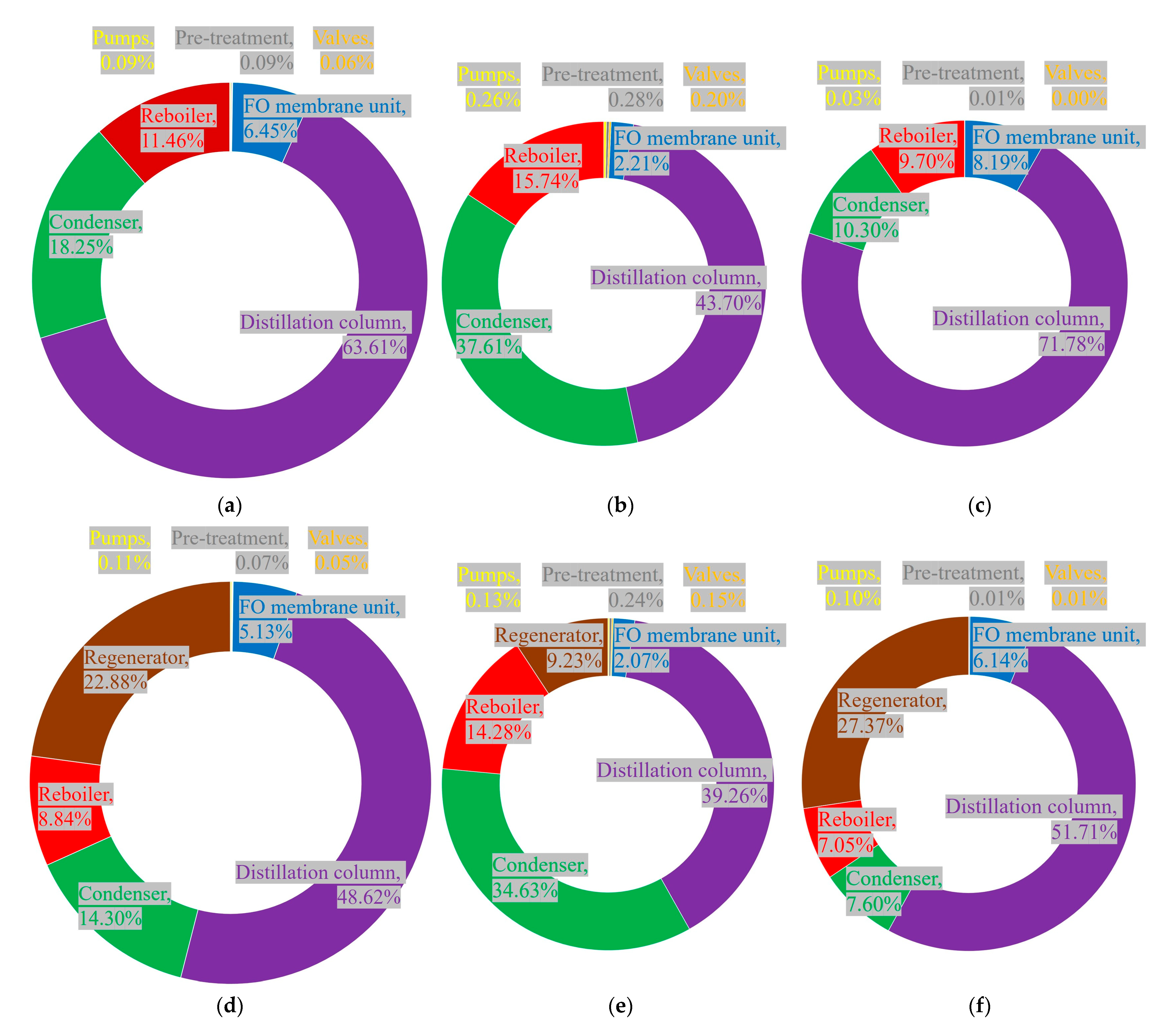
Figure 3 presents the breakdown of exergy destruction by component, excluding exergy losses to the environment. This allows for the identification of components responsible for significant exergy destruction. Figure 3a–c show the total, physical, and chemical exergy destruction, respectively, in the single-pass FO system. A comparison between Figure 3b,c indicates that, in both the condenser and reboiler, physical exergy destruction accounts for a larger share of the total exergy destruction. This form of exergy destruction primarily results from pressure differentials within the system, particularly due to the low-pressure discharge of product water and distillate from the reboiler and condenser, respectively. In contrast, the FO membrane unit exhibits a higher proportion of chemical exergy destruction, which is highly sensitive to changes in concentration and flow rate, relative to physical exergy destruction. This is attributed to its sensitivity to changes in concentration and flow rate, which arise from the concentration of feed solution and the dilution of draw solution during the osmotic process. Figure 3d–f display the total, physical, and chemical exergy destruction for the regenerative FO system, where an additional component, the regenerator, is introduced. The regenerator exhibits a dominant contribution from chemical exergy destruction, likely due to changes in the concentration and composition of the mixed solutions during the regeneration of draw solution.
Reducing exergy destruction is directly linked to improving the overall performance of the system. Based on the distribution and magnitude of exergy destruction observed in Figure 3, several strategies can be proposed to enhance system performance:
  • In the distillation column, employing a multi-effect or multi-stage configuration can reduce total exergy destruction [55,56];
  • For the FO membrane unit, selecting membranes with high water permeability and low pressure drop can help minimize physical exergy destruction [15,42,45];
  • Previous studies have also shown that connecting FO membrane units in series can reduce chemical exergy destruction by stabilizing concentration gradients across the membrane [45].

4. Conclusions

This study presented a comprehensive thermodynamic evaluation of two FO desalination configurations: the single-pass FO system and regenerative FO system. Both systems were analyzed in terms of their thermal and electrical energy requirements, exergy flows, and component-wise exergy destruction under reference environmental conditions (298.15 K, 1 atm).
The single-pass FO system, characterized by its relatively simple design, demonstrated a lower electrical energy requirement (98 kW) and higher water recovery rate (60%) compared to the regenerative system. However, it discharged a significant amount of unused exergy in the form of distillate due to the lack of solute reuse. Total exergy input for this system was calculated to be 393.1 MW, with the distillation column accounting for the largest share of exergy destruction (147.7 MW).
The regenerative FO system, on the other hand, incorporated additional components including a circulation pump, heat exchanger, and regenerator for draw solute recovery. As a result, the system exhibited an increased electrical energy demand (188.9 kW) and a slightly reduced overall water recovery rate (54%). Furthermore, the introduction of the regenerator leads to an additional exergy destruction of 57.9 MW. Despite these trade-offs, the regenerative system demonstrated a more integrated approach to solute reuse.
Component-wise exergy destruction analysis revealed that the distillation column, reboiler, and condenser were the dominant contributors to physical exergy destruction, primarily due to pressure differentials. Meanwhile, chemical exergy destruction was most prominent in the FO membrane unit and regenerator, driven by concentration and flow rate variations.
Strategies for reducing exergy destruction and enhancing the overall performance of FO desalination systems encompass several key approaches. One effective method is the implementation of multi-stage distillation columns, which can improve thermal efficiency by allowing for more gradual temperature and concentration gradients. This reduces irreversible losses associated with abrupt phase changes and pressure differentials, thereby minimizing exergy destruction within the distillation process. Another important strategy involves the selection and development of forward osmosis membranes with high water permeability and low pressure drop characteristics. Such membranes facilitate higher water flux rates at lower energy input, reducing the mechanical work required for pumping and minimizing concentration polarization effects. This not only improves membrane performance and longevity but also lowers the exergy destruction caused by solute concentration gradients across the membrane surface. Additionally, configuring FO units in series rather than in parallel can optimize the utilization of the draw solution and feedwater streams. This serial arrangement allows for staged recovery of water and solutes, effectively distributing the osmotic driving force over multiple membranes. As a result, the system achieves higher overall recovery rates and better energy integration, further reducing exergy losses. Collectively, these strategies contribute to a more integrated and efficient FO desalination process. By addressing both physical and chemical sources of exergy destruction, they pave the way for the development of FO systems that are not only more energy-efficient but also more sustainable and economically viable for large-scale water treatment applications.

Author Contributions

Conceptualization, D.K.; Methodology, C.P. and Y.K.; Software, C.P. and Y.K.; Validation, C.P. and Y.K.; Formal analysis, C.P.; Data curation, C.P.; Writing—original draft, C.P.; Writing—review & editing, C.P. and D.K.; Visualization, C.P. and Y.K.; Supervision, D.K.; Project administration, D.K. All authors have read and agreed to the published version of the manuscript.

Funding

This research received no external funding.

Conflicts of Interest

The authors declare no conflict of interest.

References

  1. Altmann, T.; Robert, J.; Bouma, A.; Swaminathan, J. Primary energy and exergy of desalination technologies in a power-water cogeneration scheme. Appl. Energy 2019, 252, 113319. [Google Scholar] [CrossRef]
  2. Water, U.N. The United Nations World Water Development Report 2021: Valuing Water; UN Water: Geneva, Switzerland, 2021. [Google Scholar]
  3. Koncagül, E.; Tran, M.; Connor, R.; Uhlenbrook, S. The United Nations World Water Development Report 2018: Nature-Based Solutions for Water; Facts and Figures. 2018. Available online: https://coilink.org/20.500.12592/jsv90z (accessed on 18 August 2025).
  4. Bank, F. World Energy Outlook 2018; International Energy Agency: Paris, France, 2018. [Google Scholar]
  5. Rosen, M.; Farsi, A. CHAPTER EIGHT—Seawater desalination systems using sustainable energy technologies. In Sustainable Energy Technologies for Seawater Desalination; Rosen, M., Farsi, A., Eds.; Academic Press: Cambridge, UK, 2022; pp. 277–360. [Google Scholar]
  6. Khan, M.A.; Rehman, S.; Al-Sulaiman, F.A. A hybrid renewable energy system as a potential energy source for water desalination using reverse osmosis: A review. Renew. Sustain. Energy Rev. 2018, 97, 456–477. [Google Scholar] [CrossRef]
  7. Dubreuil, A.; Assoumou, E.; Bouckaert, S.; Selosse, S.; Maı, N. Water modeling in an energy optimization framework—The water-scarce middle east context. Appl. Energy 2013, 101, 268–279. [Google Scholar] [CrossRef]
  8. Liu, S.Y.; Wang, Z.Y.; Han, M.Y.; Wang, G.D.; Hayat, T.; Chen, G.Q. Energy-water nexus in seawater desalination project: A typical water production system in China. J. Clean. Prod. 2021, 279, 123412. [Google Scholar] [CrossRef]
  9. Panagopoulos, A.; Haralambous, K. Environmental impacts of desalination and brine treatment-Challenges and mitigation measures. Mar. Pollut. Bull. 2020, 161, 111773. [Google Scholar] [CrossRef]
  10. Panagopoulos, A. A comparative study on minimum and actual energy consumption for the treatment of desalination brine. Energy 2020, 212, 118733. [Google Scholar] [CrossRef]
  11. Fritzmann, C.; Löwenberg, J.; Wintgens, T.; Melin, T. State-of-the-art of reverse osmosis desalination. Desalination 2007, 216, 1–76. [Google Scholar] [CrossRef]
  12. Darwish, M.A.; Al-Najem, N. The water problem in Kuwait. Desalination 2005, 177, 167–177. [Google Scholar] [CrossRef]
  13. Drioli, E.; Criscuoli, A.; Curcio, E. Integrated membrane operations for seawater desalination. Desalination 2002, 147, 77–81. [Google Scholar] [CrossRef]
  14. Malaeb, L.; Ayoub, G.M. Reverse osmosis technology for water treatment: State of the art review. Desalination 2011, 267, 1–8. [Google Scholar] [CrossRef]
  15. Rosen, M.; Farsi, A. CHAPTER TEN—Optimization of seawater desalination systems. In Sustainable Energy Technologies for Seawater Desalination; Rosen, M., Farsi, A., Eds.; Academic Press: Cambridge, UK, 2022; pp. 439–496. [Google Scholar]
  16. Okampo, E.J.; Nwulu, N. Optimisation of renewable energy powered reverse osmosis desalination systems: A state-of-the-art review. Renew. Sustain. Energy Rev. 2021, 140, 110712. [Google Scholar] [CrossRef]
  17. Rosen, M.; Farsi, A. CHAPTER SIX—Application of energy and exergy methods for assessing seawater desalination systems. In Sustainable Energy Technologies for Seawater Desalination; Rosen, M., Farsi, A., Eds.; Academic Press: Cambridge, UK, 2022; pp. 201–230. [Google Scholar]
  18. Farsi, A.; Dincer, I. Development and evaluation of an integrated MED/membrane desalination system. Desalination 2019, 463, 55–68. [Google Scholar] [CrossRef]
  19. Ali, E.; Orfi, J.; AlAnsary, H.; Soukane, S.; Elcik, H.; Alpatova, A.; Ghaffour, N. Cost analysis of multiple effect evaporation and membrane distillation hybrid desalination system. Desalination 2021, 517, 115258. [Google Scholar] [CrossRef]
  20. Jones, E.; Qadir, M.; van Vliet, M.T.H.; Smakhtin, V.; Kang, S. The state of desalination and brine production: A global outlook. Sci. Total Environ. 2019, 657, 1343–1356. [Google Scholar] [CrossRef] [PubMed]
  21. Shahzad, M.W.; Burhan, M.; Ang, L.; Ng, K.C. Energy-water-environment nexus underpinning future desalination sustainability. Desalination 2017, 413, 52–64. [Google Scholar] [CrossRef]
  22. Zarzo, D.; Prats, D. Desalination and energy consumption—What can we expect in the near future? Desalination 2018, 427, 1–9. [Google Scholar] [CrossRef]
  23. Zhu, A.; Christofides, P.D.; Cohen, Y. On RO membrane and energy costs and associated incentives for future enhancements of membrane permeability. J. Membr. Sci. 2009, 344, 1–5. [Google Scholar] [CrossRef]
  24. Castel, C.; Favre, E. Membrane separations and energy efficiency. J. Membr. Sci. 2018, 548, 345–357. [Google Scholar] [CrossRef]
  25. Suwaileh, W.; Pathak, N.; Shon, H.; Hilal, N. Forward osmosis membranes and processes: A comprehensive review of research trends and future outlook. Desalination 2020, 485, 114455. [Google Scholar] [CrossRef]
  26. Mohammadifakhr, M.; de Grooth, J.; Roesink, H.D.; Kemperman, A.J. Forward osmosis: A critical review. Processes 2020, 8, 404. [Google Scholar] [CrossRef]
  27. Francis, L.; Ogunbiyi, O.; Saththasivam, J.; Lawler, J.; Liu, Z. A comprehensive review of forward osmosis and niche applications. Environ. Sci. Water Res. Technol. 2020, 6, 1986–2015. [Google Scholar] [CrossRef]
  28. Kim, T.; Kim, Y.; Yun, C.; Jang, H.; Kim, W.; Park, S. Systematic approach for draw solute selection and optimal system design for forward osmosis desalination. Desalination 2012, 284, 253–260. [Google Scholar] [CrossRef]
  29. Ge, Q.; Ling, M.; Chung, T. Draw solutions for forward osmosis processes: Developments, challenges, and prospects for the future. J. Membr. Sci. 2013, 442, 225–237. [Google Scholar] [CrossRef]
  30. Kim, Y.; Lee, J.H.; Kim, Y.C.; Lee, K.H.; Park, I.S.; Park, S. Operation and simulation of pilot-scale forward osmosis desalination with ammonium bicarbonate. Chem. Eng. Res. Des. 2015, 94, 390–395. [Google Scholar] [CrossRef]
  31. Tsatsaronis, G.; Cziesla, F. Basic exergy concepts, exergy balance and exergetic efficiency, exergy analysis of simple processes, energetic and exergetic analysis of complex systems, strength and limitations of exergy analysis. In Encyclopedia of Life Support Systems (EOLSS), Topic Energy, Developed under the Auspices of the UNESCO; EOLSS Publishers: Oxford, UK, 2004. [Google Scholar]
  32. Aljundi, I.H. Energy and exergy analysis of a steam power plant in Jordan. Appl. Therm. Eng. 2009, 29, 324–328. [Google Scholar] [CrossRef]
  33. Ehsana, A.; Yilmazoglu, Z. Design and exergy analysis of a thermal power plant using different types of Turkish lignite. Int. J. Thermodyn. 2011, 14, 125–133. [Google Scholar] [CrossRef]
  34. Suresh, M.; Reddy, K.S.; Kolar, A.K. 3-E analysis of advanced power plants based on high ash coal. Int. J. Energy Res. 2010, 34, 716–735. [Google Scholar] [CrossRef]
  35. Elsner, W.; Kowalczyk, Ł.; Marek, M. Numerical thermodynamic optimization of supercritical coal fired power plant with support of IPSEpro software. Arch. Thermodyn. 2012, 33, 96–105. [Google Scholar] [CrossRef]
  36. Singh, O.K.; Kaushik, S.C. Variables influencing the exergy based performance of a steam power plant. Int. J. Green Energy 2013, 10, 257–284. [Google Scholar] [CrossRef]
  37. Siva Reddy, V.; Kaushik, S.C.; Tyagi, S.K. Exergetic analysis and evaluation of coal-fired supercritical thermal power plant and natural gas-fired combined cycle power plant. Clean Technol. Environ. Policy 2014, 16, 489–499. [Google Scholar] [CrossRef]
  38. Cavalcanti, E.J.; Santos, E.B.; Carvalho, M. Energetic and exergetic performances of a multi-effect desalination unit driven by a gas turbine. Environ. Prog. Sustain. Energy 2024, 43, e14324. [Google Scholar] [CrossRef]
  39. Arakcheeva El Kori, N.; Blanco-Marigorta, A.M.; Melián Martel, N. Definition of Exergetic Efficiency in the Main and Emerging Thermal Desalination Technologies: A Proposal. Water 2024, 16, 1254. [Google Scholar] [CrossRef]
  40. Patel, D.; Mudgal, A.; Patel, V.; Patel, J.; Park, K.; Davies, P.; Dhakal, N. Exergy analysis for enhanced performance of integrated batch reverse osmosis—Forward osmosis system for brackish water treatment. Desalination 2024, 580, 117548. [Google Scholar] [CrossRef]
  41. McGinnis, R.L.; Elimelech, M. Energy requirements of ammonia–carbon dioxide forward osmosis desalination. Desalination 2007, 207, 370–382. [Google Scholar] [CrossRef]
  42. Kolliopoulos, G.; Martin, J.T.; Papangelakis, V.G. Energy requirements in the separation-regeneration step in forward osmosis using TMA–CO2–H2O as the draw solution. Chem. Eng. Res. Des. 2018, 140, 166–174. [Google Scholar] [CrossRef]
  43. Sharqawy, M.H.; Zubair, S.M. On exergy calculations of seawater with applications in desalination systems. Int. J. Therm. Sci. 2011, 50, 187–196. [Google Scholar] [CrossRef]
  44. Al-Weshahi, M.A.; Anderson, A.; Tian, G. Exergy efficiency enhancement of MSF desalination by heat recovery from hot distillate water stages. Appl. Therm. Eng. 2013, 53, 226–233. [Google Scholar] [CrossRef]
  45. Patel, D.; Mudgal, A.; Patel, V.; Patel, J.; Park, K.; Davies, P.; Alegre, R.R. Energy, exergy, economic and environment analysis of standalone forward osmosis (FO) system for domestic wastewater treatment. Desalination 2023, 567, 116995. [Google Scholar] [CrossRef]
  46. Querol, E.; Gonzalez-Regueral, B.; Ramos, A.; Perez-Benedito, J.L. Novel application for exergy and thermoeconomic analysis of processes simulated with Aspen Plus®. Energy 2011, 36, 964–974. [Google Scholar] [CrossRef]
  47. Sharqawy, M.H.; Lienhard, J.H.; Zubair, S.M. Thermophysical properties of seawater: A review of existing correlations and data. Desalination Water Treat. 2010, 16, 354–380. [Google Scholar] [CrossRef]
  48. Huang, S.; Li, N.; Low, E.; Xiao, L.; Liang, C. Entropy and exergy analysis of a liquid-liquid air-gap hollow fiber membrane contactor. Int. J. Therm. Sci. 2020, 158, 106543. [Google Scholar] [CrossRef]
  49. Yangali-Quintanilla, V.; Li, Z.; Valladares, R.; Li, Q.; Amy, G. Indirect desalination of red sea water with forward osmosis and low pressure reverse osmosis for water reuse. Desalination 2011, 280, 160–166. [Google Scholar] [CrossRef]
  50. Choi, B.G.; Zhan, M.; Shin, K.; Lee, S.; Hong, S. Pilot-scale evaluation of FO-RO osmotic dilution process for treating wastewater from coal-fired power plant integrated with seawater desalination. J. Membr. Sci. 2017, 540, 78–87. [Google Scholar] [CrossRef]
  51. Zaviska, F.; Chun, Y.; Heran, M.; Zou, L. Using FO as pre-treatment of RO for high scaling potential brackish water: Energy and performance optimisation. J. Membr. Sci. 2015, 492, 430–438. [Google Scholar] [CrossRef]
  52. Nassrullah, H.; Anis, S.F.; Hashaikeh, R.; Hilal, N. Energy for desalination: A state-of- the-art review. Desalination 2020, 491, 114569. [Google Scholar] [CrossRef]
  53. Kim, J.; Park, K.; Yang, D.R.; Hong, S. A comprehensive review of energy consumption of seawater reverse osmosis desalination plants. Appl. Energy 2019, 254, 113652. [Google Scholar] [CrossRef]
  54. Chia, W.Y.; Chia, S.R.; Khoo, K.S.; Chew, K.W.; Show, P.L. Sustainable membrane technology for resource recovery from wastewater: Forward osmosis and pressure retarded osmosis. J. Water Process Eng. 2021, 39, 101758. [Google Scholar] [CrossRef]
  55. Hafiz Al Hariri, A.; Khalifa, A.E. Heat recovery of multistage circulated permeate gap membrane distillation for energy-efficient water production. Sep. Purif. Technol. 2025, 352, 128284. [Google Scholar] [CrossRef]
  56. Toth, A.J. Modelling and optimisation of multi-stage flash distillation and reverse osmosis for desalination of saline process wastewater sources. Membranes 2020, 10, 265. [Google Scholar] [CrossRef]
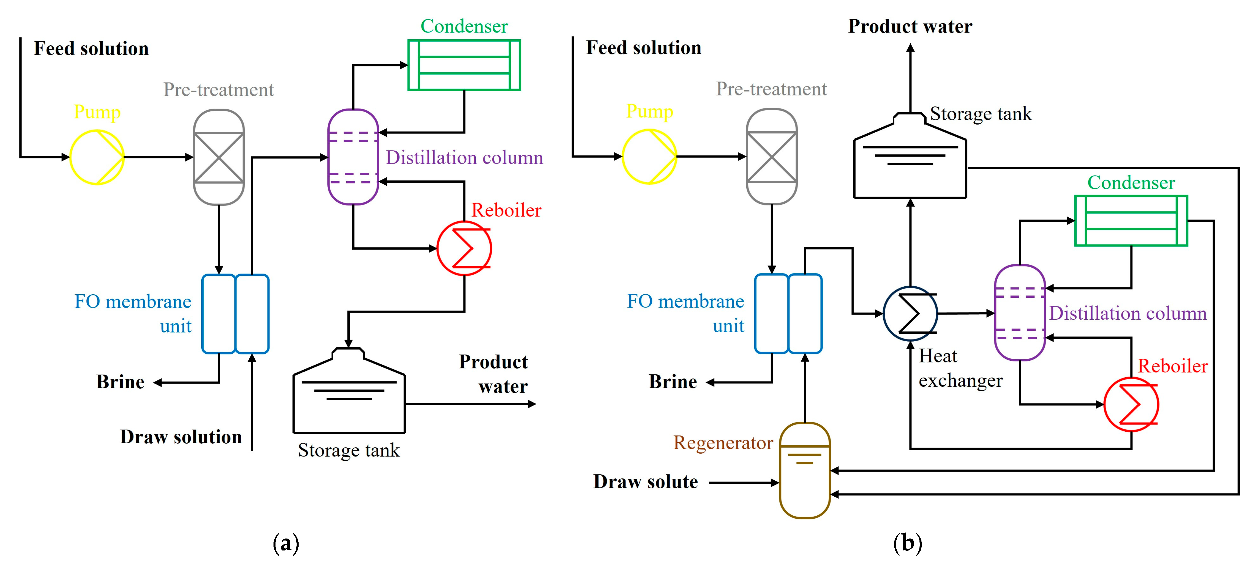
Figure 1. Schematic configurations of FO desalination systems: (a) single-pass FO system; (b) regenerative FO system.
Applsci 15 09168 g001
Figure 2. Exergy flow diagrams of FO desalination systems: (a) single-pass FO system; (b) regenerative FO system [white—exergy input, green—exergy destruction and loss, blue—exergy output].
Applsci 15 09168 g002
Figure 3. Fraction of exergy destruction in FO desalination systems: (a) total exergy destruction of single-pass FO system; (b) physical exergy destruction of single-pass FO system; (c) chemical exergy destruction of single-pass FO system; (d) total exergy destruction of regenerative FO system; (e) physical exergy destruction of regenerative FO system; (f) chemical exergy destruction of regenerative FO system [yellow—pumps, gray—pre-treatment, orange—valves, blue—FO membrane unit, purple—distillation column, green—condenser, red reboiler, brown—regenerator].
Applsci 15 09168 g003
Table 1. Energy analysis summary of FO desalination systems.
Single-Pass
FO Desalination System
Regenerative
FO Desalination System
Thermal energy consumption114.5 MW114.5 MW
Electrical energy consumption98.1 kW188.9 kW
Salt rejection rate98%98%
Water recovery rate60%54%
Equivalent work1.4 kWh/m31.8 kWh/m3
Disclaimer/Publisher’s Note: The statements, opinions and data contained in all publications are solely those of the individual author(s) and contributor(s) and not of MDPI and/or the editor(s). MDPI and/or the editor(s) disclaim responsibility for any injury to people or property resulting from any ideas, methods, instructions or products referred to in the content.