Abstract
Curved prisms can serve as core components of dispersive spectroscopy and converge light paths, making them widely used in spectral imaging technology. Their positional stability, surface shape errors, and temperature stability in optical systems directly affect the performance of spectral imaging systems. On the basis of the analysis of design indicators and optimization of the support structure for curved prisms, a multipoint flexible adhesive support structure (MPPASS) of large rectangular curved prisms for space-based application is proposed. The novelty of the MPPASS lies in its ability to achieve micro-stress and high stability support for large-aperture rectangular optical elements through the bonding of peripheral small points and the introduction of flexible bonding rings. The design principles of the adhesive support structure were deeply studied, and on this basis, the engineering design, finite element analysis, adhesive testing, and mechanical testing of large curved prisms were completed. The designed curved prism assembly has a maximum deformation displacement of 0.0085 mm and a maximum tilt angle of 0.65” under gravity loading, a first-order frequency of 1003.5 Hz, and a maximum acceleration amplification factor of 3.12 in the X, Y, and Z directions. The root mean square (RMS) variation value of the mirror shape errors for the curved prism assembly was 5.26 nm under a uniform temperature load of 20 ± 1 °C, and the RMS value of the mirror shape errors was 0.019 λ after mechanical testing. The installation surface flatness of 0.02 mm did not significantly affect its mirror shape errors. The experimental results verified the rationality of the design, temperature stability, and mechanical stability of the MPPASS.
1. Introduction
Compared with traditional cameras, imaging spectrometers can obtain physical attribute information related to detection targets and the backgrounds of segmented narrowband spectra, so they can better achieve camouflage exposure and target recognition. Therefore, they are widely used in resource monitoring, land surveying, ocean observation, and military identification [1,2,3,4,5]. The spectral element is an indispensable and important component in spectroscopic instruments for dividing the spectral narrowband of wide bands that directly determine the spectral performance of the system.
At present, the most widely used spectral elements in spaceborne applications are gratings and prisms [6,7]. Compared with grating splitting, prism splitting does not experience overlapping spectral orders, has a large light flux, and has high sensitivity for spectral analysis. However, prism dispersion experiences a strong dispersion nonlinearity problem that can be overcome by curved prisms. In addition to the dispersion advantages of traditional prisms, curved prisms also have collimation and certain imaging functions, which can eliminate the need for collimation optical element design and significantly reduce the volume of the optical system. They can also correct aberrations, greatly improving the imaging quality and overall performance of the system.
Prism dispersion can be further divided into planar prism dispersion and curved prism dispersion. Traditional planar prism dispersion requires the addition of a collimation system in the imaging optical path, which complicates the optical system. However, curved prisms, due to their inherent ability to converge the light path, can eliminate the need for a collimation system, significantly simplifying the dispersion imaging system and facilitating miniaturization design. However, a curved prism is a nonrotational symmetrical body, and the traditional fixation method of the frame and pressure ring has difficulty achieving high-precision and high-stability installation [8]. Small, circular curved prisms (≤150 mm) can be supported for microstress by creating bosses on the circumferential surface of the prism during optical processing and adding rubber pads between the pressure ring and the mirror. As the effective aperture of curved prisms is often elliptical, larger curved prisms (200–600 mm) are often processed into rectangles to reduce the volume and weight of the system.
The difficulty of supporting structures for large rectangular prisms lies in ensuring surface shape errors, mechanical vibration reliability, and temperature stability of the prism in various space-based environments. Therefore, it is necessary for its supporting structure to have both high stiffness and flexible stress release capabilities. The commonly used method for the support structure of the rectangular curved prisms was through the use of an elastic clamping plate. However, this method could result in significant clamping stress due to direct contact between the clamping plate and the mirror. A multipoint peripheral adhesive support structure (MPPASS) for curved prisms that can achieve an RMS value of surface shape errors <(1/50)λ, even under the influence of gravity, temperature, manufacturing error, assembly error, and other factors, is proposed. A multipoint peripheral adhesive support structure (MPPASS) with micro-stress, high strength, and thermal stability for rectangular curved prisms is proposed. The research methodology was shown in Figure 1. The core and innovation lie in the calculation of bonding area, the layout of bonding points, and the design of flexible bonding rings.
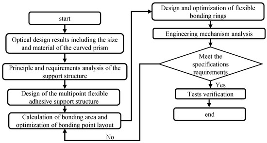
Figure 1.
The research methodology of the MPPASS.
The rest of this paper is organized according to the research framework presented in Figure 1. Firstly, the design principles and requirements of the curved prism support was described in Section 2. Section 3 explains the design and optimization of the support structure. Section 4 and Section 5, respectively, introduce the engineering mechanics analysis and experimental verification results for the MPPASS. Section 6 presents the conclusions and introduces future work.
2. Analysis of the Support Structure Requirements
2.1. Structural Parameters of the Curved Prism
The difficulty of support for the curved prisms lies in its non-rotational symmetry. Therefore, precise phase adjustment of the curved prism was required in the optical system to achieve good imaging quality. The detailed dimensional parameters of the curved prism are shown in Figure 2. The material of the curved prism was H-TF8, which was used for visible imaging. The off-axis distance between the front and rear surfaces of the curved prism was 30.61 mm. The curvature radii of the front and back surfaces were 435.49 mm and 460.72 mm, respectively. The geometric dimensions of the mirror body were 230 × 166 mm. A 2% margin has been reserved for the optical effective aperture to avoid edge effects during mirror processing. The RMS value of the surface shape error for the bare curved prism was 0.018λ.
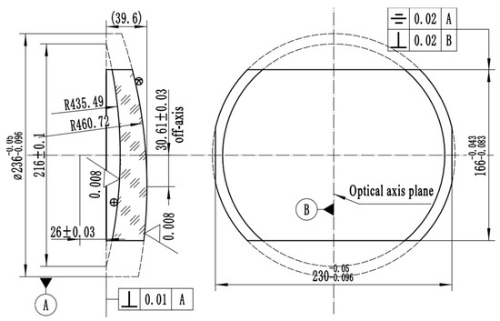
Figure 2.
Structural parameters of the curved prism.
2.2. Design Index Analysis of the Curved Prism Support Structure
To achieve the dispersion and convergence light path effects of curved prisms in dispersion spectral imaging systems, the design indicators of the MPPASS for curved prisms were as follows:
- The surface shape error (RMS) of the curved prism assembly (CPS) after mechanical testing should be <(1/50)λ. The surface shape errors of a curved prism are related to factors such as the material of the mirror body, differences in mirror body thickness, position of bonding points, area of individual bonding points, and form of the support structure. Therefore, the form, position, and layout of the adhesive structure must be optimized and analyzed.
- The surface shape error of the CPS remains unchanged at 20 ± 1 °C. This requires the bonding structure of the curved prism to have a certain degree of flexibility to release the stress introduced by temperature changes while ensuring rigidity. In addition, optomechanical thermal coupling analysis must be performed to optimize the MPPASS.
- The support structure should possess sufficient rigidity to ensure that the rigid displacement of the mirror is <0.01 mm under gravity.
- The inclination angle of the mirror in the direction of gravity should be <2” under gravity. This requires the support points in the support structure to pass through the center of gravity of the mirror body to maintain mirror balance and decrease the inclination angle.
- The mass of the SRCPS should be <4.5 kg. For space payloads, the mass determines the launch cost. Therefore, the mass of the optical components should be reduced as much as possible. This requires the use of materials with higher stiffness and a reasonable and sufficient lightweight design.
- The first fundamental frequency of the CPS should be >300 Hz to avoid the resonance peak of the entire satellite and ensure good mechanical properties when it is integrated into the box.
- The dynamic stress on the support structure should be <800 MPa, which is the allowable stress on the flexible structure. The dynamic stress on the curved prism should be <20 MPa, which is the allowable stress for optical materials. The dynamic stress on the adhesive should be <15 MPa, which is the bonding strength of the adhesive.
- The amplification of the RMS acceleration of the CPS should be <4. The larger the amplification of the RMS acceleration of the SRCPS is, the worse the overall stiffness of the support structure.
- The CPS should be designed with a back plate to achieve radiation resistance for spaceborne applications, avoiding the reduction in transmittance caused by radiation effects on optical materials and affecting imaging performance. This requires the antiradiation backplate to be designed with a flexible structure to unload the screw torque of the installation screws to avoid directly affecting the surface shape errors of the curved prism.
Among the above indices, the CPS must be fixed via small multipoint bonding forms, and the bonding points should be as close as possible to the center of mass. While ensuring the stiffness and strength of the supporting structure, a flexible structure must be designed to unload the assembly stress, temperature stress, and installation stress and ensure low surface shape errors [9,10,11]. Therefore, the MPPASS for large spaceborne rectangular curved prisms is proposed.
2.3. Design Principles for Adhesive Support Structures
For the highly stable and reliable MPPASS of large curved prisms, the following three aspects should be ensured. First, the RMS error value for the surface shape of the curved prism after bonding and curing in the frame must not exceed (1/50)λ. Several methods can achieve high surface shape errors, including the following: 1. Optical materials with a higher stiffness ratio should be used as much as possible to improve the stiffness of the mirror itself. 2. Assuming a fixed total bonding area, multiple small-area adhesives should be used as much as possible to minimize the impact of adhesive curing on the mirror surface shape. 3. The design and layout of the bonding points should be optimized as much as possible to reduce the degree of tilt of the mirror itself (e.g., the bonding points should pass through the center of mass of the mirror body, flexible bonding structures should be introduced to release bonding and assembly stresses [9,12], the bonding points should be arranged as symmetrically as possible, and the overturning moment introduced by the support structure should be reduced). In addition, the supporting structure and form must have sufficient rigidity and strength to ensure that the surface shape errors of the curved prism assembly do not change under gravity along the X, Y, and Z axes.
Second, the curved prism assembly must have excellent mechanical and thermal stability [13,14]. For support structures that use adhesive bonding, the mechanical condition inputs, unstable bonding processes, and unsatisfactory bonding interfaces must be fully considered when the bonding area is designed. A sufficient design margin for the bonding area should be introduced to achieve high mechanical stability. To achieve high thermal stability, appropriate optomechanical adhesives must be selected, the thermal expansion coefficients of different types of materials must be matched, and scientifically and reasonably flexible structures must be used to release thermal stress.
Finally, and most importantly, the spatial position of the curved prism and its relative position with respect to other mirror components must be ensured. A curved prism is a nonrotational symmetric body, so all six degrees of freedom in space must be adjusted. During structural design, a portion of the degrees of freedom must be constrained through benchmark transformation, and, at the same time, the other degrees of freedom must be fine-tuned through design adjustment steps (such as controlling the degrees of freedom of movement with a limit table and adding trimming pads and screw holes to adjust the position and posture of the mirror). In addition, the repeated disassembly and assembly of curved prisms must be considered during the assembly and adjustment process, and their reset design (such as pin reset, reset fixtures, or optical monitoring methods) must be considered. In addition, the reset design of a curved prism assembly that needs to be disassembled and reassembled multiple times during the integration process (such as pin hole, reset tooling, or optical monitoring methods) must be considered.
3. Design of the Multipoint Flexible Adhesive Support Structure
3.1. Overall Design
The MPPASS for the curved prism proposed was fixed by bonding 8-point epoxy adhesive around the edges. A three-dimensional schematic diagram of the support structure is shown in Figure 3. The curved prism was installed in the mirror frame, and the internal cavity size of the mirror frame was 1 mm larger than the external dimensions of the curved prism, ensuring that the curved prism was in a free state in the curved prism frame. The curved prism was fixed by bonding with eight adhesive points on four sides. On the left and right sides, the side of the prism with thicker edges was fixed with rigid adhesive rings, and the end with thinner edges was fixed with flexible adhesive rings. The lower side was bonded with a rigid adhesive ring, whereas the upper side was bonded with a flexible adhesive ring. This bonding technique did not over-constrain the mirror body through the design of flexible bonding rings, which was a core advantage, and prevented stress concentration and stability issues caused by full rigid bonding and full flexible bonding. In addition, ensuring that the eight adhesive points passed through the center of mass of the curved prism as much as possible achieved a better stress state. There was a trimming pad between each adhesive ring and the curved prism frame, which could be used to adjust and control the thickness of the adhesive layer to ensure adhesive strength. There were two 6 mm injection holes on each side of the curved prism frame for injecting the XM-31 adhesive. The purpose of the injection holes was to assist in the position and posture accuracy of the curved prism before epoxy adhesive bonding and to enhance the reliability of the mirror assembly in terms of bonding. The epoxy adhesive was EC2216-B/A, which is widely used in aerospace optical instruments because of its high strength, low stress, and nonvolatility [15,16]. The design mass of the MPPASS was 3.95 kg.
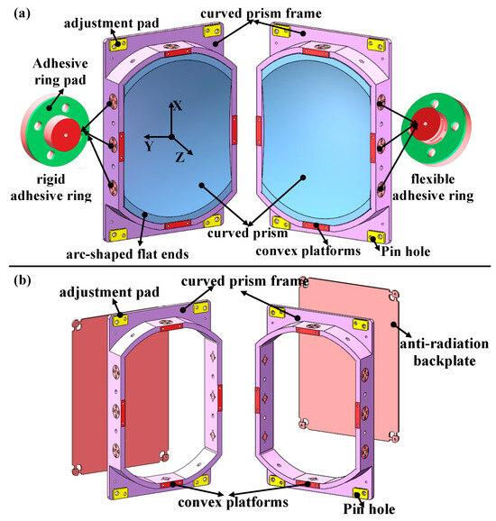
Figure 3.
MPPASS of the spaceborne rectangular curved prism: (a) assembly; (b) structure without a prism.
For a fixed bonding area, increasing the number of bonding points appropriately can reduce the bonding area of a single point, thereby reducing the impact of adhesive curing stress on the surface shape errors of the curved prism. Arranging adhesive points on the upper and lower sides of a rectangular curved prism could improve the force balance of the mirror assembly under gravity in the X and Y directions and ensure the stability of posture changes in the three spatial axes during integration. The curved prism frame was designed with four protrusions on the front surface, which could be used as the installation surface for the bonding fixture. The axial positional accuracy of the curved prism was ensured through the bonding fixture. The four convex platforms must be grinded to ensure a coplanarity of less than 0.01 mm. After bonding is complete and the bonding fixture is removed, it can still be used as an installation position for the precision measuring mirror to monitor the position and posture of the curved prism during the system integration stage.
In terms of material selection for the structure, the main consideration is thermal expansion matching and a lightweight design. The adhesive ring in direct contact with the optical components was made of a titanium alloy TC4 material whose linear expansion coefficient was similar. To reduce the weight of the system and improve the stiffness, the curved prism frame was made of aluminum-based silicon carbide (AlSiC). The selection of other materials is shown in Table 1.

Table 1.
Material and performance parameters of the CPS.
The bonding surfaces of the adhesive rings were sandblasted to ensure a roughness of 3.2–6.4 μm to achieve high bonding strength. The flexible slots in flexible adhesive rings were formed through wire cutting machining. The flexible adhesive rings were iteratively optimized via a genetic algorithm to obtain the optimal size and distribution of the flexible groove, as shown in Figure 4 [17,18]. The detailed optimization design of flexible adhesive rings will be further detailed in subsequent publications.

Figure 4.
Structure of the adhesive rings: (a) rigid adhesive rings and (b) flexible adhesive rings.
3.2. Theoretical Calculation of the Bonding Area
The curved prism was fixed by peripheral epoxy adhesive. The EC2216-B/A epoxy adhesive was injected between the flexible ring and the optical element through the injection hole during bonding. The thickness of the adhesive was controlled by trimming the adhesive ring pads between the flexible ring and the curved prism frame. The thickness of the adhesive was generally controlled at 0.1 ± 0.02 mm.
The larger the bonding area, the better the mechanical stability of the CPS. However, the larger the bonding area, the greater the introduced bonding stress, which could lead to poorer surface shape errors. Therefore, it was crucial to choose a reasonable bonding area that can ensure both mechanical stability and surface shape errors.
The minimum bonding area between the optical and structural parts was calculated according to the following empirical formula [19]:
where S is the minimum bonding area, w is the mass of the optical element, ag is the maximum acceleration, fs is the safety factor, and J is the shear strength or tensile strength of the adhesive.
Given the insufficient cleaning of the surface during bonding treatment, the value of fs was 4. The maximum acceleration was 20 g. The shear strength of the adhesive was 10 MPa. The minimum bonding area of the curved prism was then calculated according to the above formula. Considering the feasibility of processing, operability of bonding technology, and high design redundancy, the final design dimensions and bonding area of the bonding ring are listed in Table 2.
Table 2.
Bonding area of the rectangular curved prism.
On the basis of the above analysis results, the designed bonding area of the curved prism was much larger than the theoretical minimum bonding area, which could ensure the bonding strength and mechanical reliability of the CPS. The adhesive design area of the CPS was based on the theoretical calculation values mentioned above, and further confirmation of its rationality and reliability through engineering mechanics analysis is still needed.
3.3. Optimization of Multipoint Bonding Forms
When designing the MPPASS, a total of nine structural support forms were proposed for screening, as shown in Figure 5. All nine structural support forms should ensure that the bonding point passes through the center of mass of the curved prism to minimize the impact of the overturning moment on the surface shape errors of the curved prism. To ensure the same bonding area, a detailed structural design was carried out for the nine types of CPSs mentioned above. After the design was completed, the surface shape errors (RMSs) of the CPS under self-weight and a uniform temperature load of 1 °C were analyzed. The analysis results are shown in Table 3.
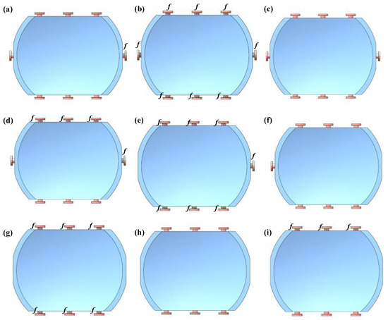
Figure 5.
All 9 structural support forms: (a) 4-sided bonding (3 sides rigid, 1 side flexible); (b) 4-sided bonding (4 sides flexible); (c) 4-sided bonding (4 sides rigid); (d) 4-sided bonding (2 sides rigid, 2 sides flexible); (e) 3-sided bonding (3 sides flexible); (f) 3-sided bonding (3 sides rigid); (g) 2-sided bonding (2 sides flexible); (h) 2-sided bonding (2 sides rigid); and (i) 2-sided bonding (1 side rigid, 1 side flexible). f represents the flexible adhesive ring.
Table 3.
Variation in the RMS value for the surface shape errors of CPSs with different support forms.
Considering the coupling effect of the gravity load and temperature load on the surface shape errors of the CPS, the weights of the two were set to 0.5, and the variation in the RMS value for the surface shape errors under the coupling effect on the two loads was calculated as follows:
where δ1 represents the maximum surface shape error (RMS) of the CPS under three-axis gravity and where δ2 represents the maximum surface shape error (RMS) of the CPS under a uniform 1 °C load.
In summary, the four-sided adhesive (two sides rigid, two sides flexible) was adopted as the basic support structure for the CPS, as shown in Figure 5d.
4. Engineering Mechanics Analysis
Spaceborne optical equipment is subject to complex environments and exposed to vibrations, impact, and temperature changes during launch and ignition. To ensure imaging quality, finite element analysis is widely used in the design process [20,21]. In accordance with the design requirements, static analysis, modal analysis, temperature load analysis, flatness sensitivity analysis, and random vibration analysis were conducted on the CPS. In the analysis process, the optical axis of the CPS was defined as the Z-axis, the X-axis was parallel to the short side of the CPS, and the Y-axis was determined by the right-hand rule, as shown in Figure 2.
4.1. Static Analysis
To verify the static characteristics of the CPS, an analysis was conducted on its surface shape errors under the coupling of 1 g gravity and an installation surface flatness of 0.01 mm. The distribution results of the surface shape cloud map are shown in Figure 6, and the RMS variation values of the surface shape errors are shown in Table 4.
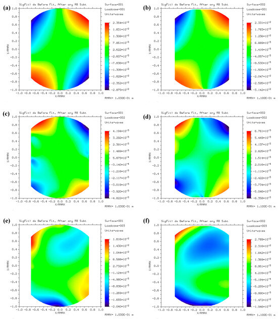
Figure 6.
Surface shape cloud map of the CPS under the coupling of 1 g gravity and an installation surface flatness of 0.01 mm: (a) concave surface cloud map with gravity in the X direction; (b) convex surface cloud map with gravity in the X direction; (c) concave surface cloud map with gravity in the Y direction; (d) convex surface cloud map with gravity in the Y direction; (e) concave surface cloud map with gravity in the Z direction; and (f) convex surface cloud map with gravity in the Z direction.
Table 4.
RMS variation values for the surface shape errors of the CPS under coupled static working conditions.
The maximum RMS variation in the surface shape errors of the CPS under coupling conditions was 6.45 nm, approximately (1/100)λ. The maximum deformation displacement of the CPS under uniaxial gravity was 0.0055 mm, and the maximum tilt angle was 0.65″. The influence of gravity and installation surface flatness on the surface shape errors of curved prisms was relatively minor, which verified the rationality of the MPPASS.
4.2. Modal Analysis
To avoid resonance phenomena caused by the proximity of the CPS to the satellite frequency during satellite launch, which could decrease optical performance, modal analysis was performed. The first-order mode of the CPS obtained through modal analysis was 1005.1 Hz, which was much higher than the required 300 Hz as shown in Figure 7. This indicated that the CPS had excellent dynamic mechanical performance.
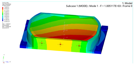
Figure 7.
First natural vibration mode of the CPS.
4.3. Temperature Sensitivity Analysis
The imaging performance and spectral performance of spaceborne hyperspectral imagers are strongly affected by temperature, especially for large aperture lenses, which are more sensitive to temperature. To verify the adaptability of the MPPASS to the imaging temperature, an analysis was conducted on the RMS variation in the surface shape errors of the CPS under a uniform temperature variation load (20 ± 1 °C).
The surface shape error (RMS) changes in the concave and convex surfaces of the CPS under a uniform temperature variation load of 20 ± 1 °C were 5.27 nm and 5.20 nm, respectively, as shown in Figure 8.
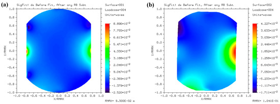
Figure 8.
Surface contour cloud map of the CPS with uniform temperature variation (20 ± 1 °C): (a) cloud map with a concave surface shape and (b) convex surface contour cloud map.
4.4. Sensitivity Analysis of the Flatness of the Antiradiation Backplate
Lens assemblies bonded with epoxy adhesive are often strongly affected by the installation stress because of their high fundamental frequency and high rigidity. The antiradiation backplate of the CPS must be installed after the epoxy adhesive is cured because the unevenness of the installation surface may introduce stress and cause changes in the surface shape errors of the CPS. Therefore, a flexible structure was introduced to relieve stress in the design (as shown in Figure 9), and an analysis was conducted on the influence of the flatness of the antiradiation backplate on the surface shape errors of the CPS. The numbers 1–4 represented four installation bosses in Figure 9. The differences in the installation flatness values are simulated by setting the force displacement on the installation points. The analysis revealed that when the flatness difference in the antiradiation backplate was 0.02 mm, an assembly stress was introduced, resulting in a 0.06 nm change in the RMS value of the surface shape errors of the CPS, and the impact could be ignored.
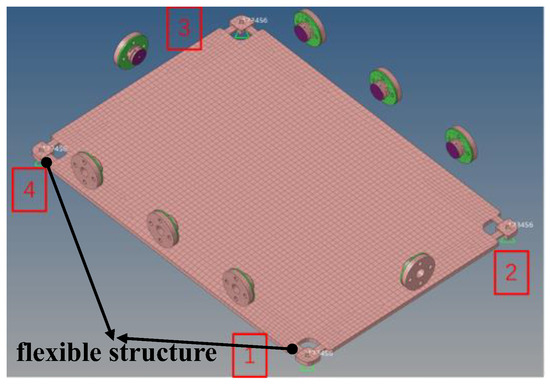
Figure 9.
Forced displacement of 0.02 mm applied at points 1 and 3.
4.5. Random Vibration Analysis
To evaluate the dynamic mechanical performance of the CPS, a random vibration mechanics analysis was conducted according to the mechanical conditions in Table 5. The stress distributions of the adhesive layer, optical elements, and structural parts under random vibration mechanics conditions are shown in Figure 10. The maximum dynamic stresses of the adhesive layer in the X, Y, and Z directions were 2.96 MPa, 1.2 MPa, and 2.43 MPa, respectively. The maximum dynamic stresses of the optical elements in the X, Y, and Z directions were 0.95 MPa, 0.49 MPa, and 0.64 MPa, respectively. The maximum dynamic stresses of the structural parts in the X, Y, and Z directions were 20.58 MPa, 8.49 MPa, and 17.53 MPa, respectively. The maximum acceleration magnifications of the CPS in the X, Y, and Z directions were 2.12, 2.85, and 3.24, respectively, all of which were lower than the designed acceleration magnifications of the requirements. The maximum dynamic stress obtained from simulation was less than the allowable stress of the material, and it proved that the CPS could withstand the random vibration dynamics of the analyzed magnitude.
Table 5.
Random vibration test conditions of the SRCPS.
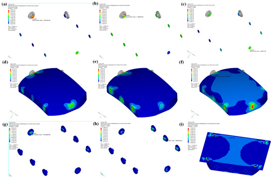
Figure 10.
Statistical stress for the CPS in the random vibration simulation: (a) stress of the adhesive layer in the X direction; (b) stress of the adhesive layer in the Y direction; (c) stress of the adhesive layer in the Z direction; (d) stress of the optical element in the X direction; (e) stress of the optical element in the Y direction; (f) stress of the optical element in the Z direction; (g) stress of the structural parts in the X direction; (h) stress of the structural parts in the Y direction; and (i) stress of the structural parts in the Z direction.
5. Assembly and Verification
5.1. Tests of the Displacement, Inclination Angle, and Mass
After the design results were verified through engineering mechanics analysis, the CPS could be integrated and tested to verify the performance of the support structure. After injecting epoxy adhesive, the curved prism was left to cure for 7 days (as shown in Figure 11). The displacement, inclination angle, and mass of the CPS were tested by using a digital display micrometer, a theodolite, and an electronic balance, respectively. The displacement, inclination angle, and mass of the CPS were ~0.006 mm, ~1.2″, and 4.01 kg, respectively. All of which are better than the design index values.
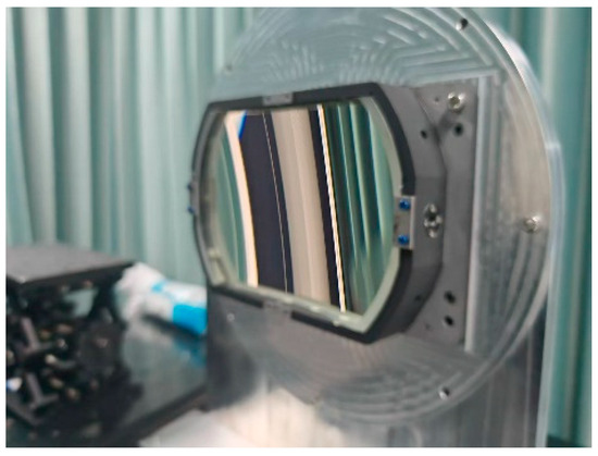
Figure 11.
Curved prism assembly.
5.2. Vibration Test
After 7 days of adhesive curing, the curved prism was subjected to random vibration testing, as shown in Figure 12. The random vibration results revealed that the first-order frequency of the CPS was 1003.5 Hz, and the X, Y, and Z three-axis acceleration amplification factors were 2.21, 2.75, and 3.12, respectively. The experimental results were almost consistent with the simulation results. Because the maximum acceleration amplification factor was less than 4, the design specifications met the requirements. After the vibration test, no peeling or cracking of the adhesive layers was observed in the adhesive spots of the CPS by visual inspection. The scanning frequency test curves before and after the random vibration test remained consistent. The CPS successfully withstood the random vibration test in Table 5.
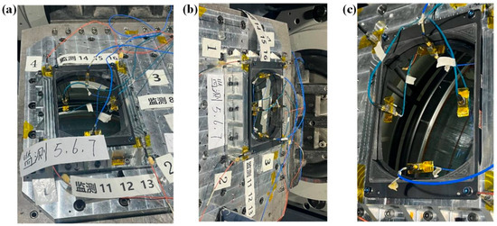
Figure 12.
Mechanical testing of the CPS: (a) vibration test in the X direction; (b) vibration test in the Y direction; and (c) vibration test in the Z direction.
5.3. Test of the Surface Shape Errors
The RMS value of the surface shape errors of the curved prism before and after the mechanical test were 0.022λ and 0.019λ, respectively. It met the requirement necessitating that the RMS value of the surface shape errors be <(1/50)λ, as shown in Figure 13. Before and after the mechanical testing, there was no significant change in the surface shape errors of the CPS, further verifying the rationality of the design.
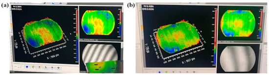
Figure 13.
The surface shape errors of the CPS at different stages. (a) After epoxy adhesive bonding and curing. (b) After random vibration.
Using the abovementioned MPPASS, bonding tests of two other curved prisms of similar sizes were performed, and the results successfully passed the mechanical test assessment, verifying the universality of the support technology and the stability of the bonding process, as shown in Figure 14.
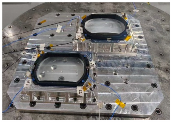
Figure 14.
Two other curved prisms bonded via similar support technology.
6. Conclusions
The rectangular curved prism was the core optical element of the imaging spectrometer. A multipoint flexible adhesive support structure for large space-based rectangular curved prisms was proposed on the basis of the characteristics, design index requirements, and adhesive support structure design principles of curved prisms. On this basis, the engineering design, the optimization of the multipoint adhesive form, and the analyses of engineering mechanics—including static analysis, modal analysis, temperature sensitivity analysis, installation flatness sensitivity analysis, and random vibration mechanics analysis—were completed for the large curved prisms, which verified the high reliability and stability of the structural design. Furthermore, experimental verification of the mass, displacement, inclination angle, random vibration test, surface shape error test, and similar mirror group bonding test, was carried out on the curved prism assembly. The experimental results verified the rationality and universality of the design of the proposed multipoint flexible adhesive support structure, as well as the stability and operability of the bonding process.
Author Contributions
Conceptualization, X.J. and S.L.; Data curation, B.H.; Formal analysis, J.L.; Funding acquisition, X.J.; Investigation, J.L.; Methodology, X.J. and X.H.; Project administration, X.J.; Resources, S.L. and B.H.; Software, B.H.; Supervision, S.L.; Visualization, X.H.; Writing—original draft, X.J.; Writing—review and editing, X.J. All authors have read and agreed to the published version of the manuscript.
Funding
This research was funded by National Natural Science Foundation of China under Grants 42306202 and China Postdoctoral Science Foundation under Grants 2024M763919.
Institutional Review Board Statement
Not applicable.
Informed Consent Statement
Not applicable.
Data Availability Statement
The raw data supporting the conclusions of this article will be made available by the authors on request.
Acknowledgments
The authors are grateful to the Second Institute of Oceanography and Xi’an Institute of Optics and Precision Mechanics to provide the test platform. They also thank the editors and reviewers for providing many constructive suggestions that helped to improve this manuscript significantly.
Conflicts of Interest
The authors declare that they have no known competing financial interests or personal relationships that could have appeared to influence the work reported in this paper.
Abbreviations
The following abbreviations are used in this manuscript:
| MPPASS | Multipoint flexible adhesive support structure |
| RMS | Root mean square |
| CPS | Curved prism assembly |
References
- Qian, S.E. Hyperspectral satellites, evolution, and development history. IEEE J. Sel. Top. Appl. Earth Obs. Remote Sens. 2021, 14, 7032–7056. [Google Scholar] [CrossRef]
- Su, H.; Wu, Z.; Zhang, H.; Du, Q. Hyperspectral anomaly detection: A survey. IEEE Geosci. Remote Sens. Mag. 2021, 10, 64–90. [Google Scholar] [CrossRef]
- Yang, H.; Chen, C.; Ni, J.; Karekal, S. A hyperspectral evaluation approach for quantifying salt-induced weathering of sandstone. Sci. Total Environ. 2023, 885, 163886. [Google Scholar] [CrossRef] [PubMed]
- Datta, D.; Mallick, P.K.; Bhoi, A.K.; Ijaz, M.F.; Shafi, J.; Choi, J. Hyperspectral image classification: Potentials, challenges, and future directions. Comput. Intell. Neurosci. 2022, 2022, 3854635. [Google Scholar] [CrossRef] [PubMed]
- Grøtte, M.E.; Birkeland, R.; Honoré-Livermore, E.; Bakken, S.; Garrett, J.L.; Prentice, E.F.; Sigernes, F.; Orlandić, M.; Gravdahl, J.T.; Johansen, T.A. Ocean color hyperspectral remote sensing with high resolution and low latency—The HYPSO-1 CubeSat mission. IEEE Trans. Geosci. Remote Sens. 2021, 60, 1–19. [Google Scholar] [CrossRef]
- Féry, C. A Prism with Curved Faces, for Spectrograph or Spectroscope. Astrophys. J. 1911, 34, 79. [Google Scholar] [CrossRef]
- Sang, B.; Schubert, J.; Kaiser, S.; Mogulsky, V.; Neumann, C.; Forster, K.P.; Hofer, S.; Stuffler, T.; Kaufmann, H.; Muller, A.; et al. The EnMAP hyperspectral imaging spectrometer: Instrument concept, calibration, and technologies. Proc. SPIE 2008, 7086, 708605. [Google Scholar]
- Yoder, P.R. Mounting Optics in Optical Instruments; SPIE Publications: Bellingham, WA, USA, 2002. [Google Scholar]
- Zhu, Z.; Tian, A.; Liu, B.; Wu, Y.; Dong, S. Design and evaluation of flexible support based on space mirror. Appl. Sci. 2024, 14, 1927. [Google Scholar] [CrossRef]
- Shen, X.; Sun, X.; Wang, C.; Yang, Y.; Sun, L.; Chen, J.; Sun, S. Topology optimization of a double-sided space mirror based on additive manufacturing of SiC. Struct. Multidiscip. Optim. 2024, 67, 130. [Google Scholar] [CrossRef]
- Han, W.; Shao, S.; Zhang, S.; Tian, Z.; Xu, M. Design and modeling of decoupled miniature fast steering mirror with ultrahigh precision. Mech. Syst. Signal Process. 2022, 167, 108521. [Google Scholar] [CrossRef]
- Liu, X.; Gu, K.; Li, M.; Cheng, Z. Optimization design of large-aperture primary mirror for a space remote camera. Sensors 2023, 23, 5441. [Google Scholar] [CrossRef] [PubMed]
- Bae, J.H.; Park, K.W. Optomechanical Performance of Adhesive Bonding in Airborne EO/IR Systems: A Comparative Study of Bonding Configurations. Curr. Opt. Photonics 2025, 9, 239–246. [Google Scholar]
- Wu, W.; Lin, G.; Zhang, Z.; Zhu, J.; Li, J.; He, L. Research on the High Tolerance Flexible Support Structure for the Primary Mirror in Cassegrain Optical Systems. Photonics 2025, 12, 173. [Google Scholar] [CrossRef]
- Kihm, H.; Yang, H.S.; Lee, Y.W. Athermal Lens Mount with Ring Flexures. J. Korean Phys. Soc. 2011, 59, 3356–3362. [Google Scholar] [CrossRef]
- Lee, D.; Hao, Y.; Park, J.; Kang, I.S.; Kim, S.H.; Li, J.; Rho, J. Singular lenses for flexural waves on elastic thin curved plates. Phys. Rev. Appl. 2021, 15, 034039. [Google Scholar] [CrossRef]
- Yong, Y.K.; Lu, T.F.; Handley, D.C. Review of circular flexure hinge design equations and derivation of empirical formulations. Precis. Eng. 2008, 32, 63–70. [Google Scholar] [CrossRef]
- Wu, Y.; Zhou, Z. Design calculations for flexure hinges. Rev. Sci. Instrum. 2002, 73, 3101–3106. [Google Scholar] [CrossRef]
- Yoder, P.R. Opto-Mechanical Systems Design, 3rd ed.; CRC Press, Inc: Boca Raton, FL, USA, 2005. [Google Scholar]
- Wang, K.; Dong, J.; Wang, X.; Chi, C. Design of frame-type support structure for space-based rectangular convex mirror tested on the back. Optik 2020, 212, 164673. [Google Scholar]
- Zhang, L.; Wang, W.; Wang, J.; Guo, P.; Hao, L. Design and analysis for the multi-point flexible support structure of large and precision lens. Optik 2019, 193, 162966. [Google Scholar] [CrossRef]
Disclaimer/Publisher’s Note: The statements, opinions and data contained in all publications are solely those of the individual author(s) and contributor(s) and not of MDPI and/or the editor(s). MDPI and/or the editor(s) disclaim responsibility for any injury to people or property resulting from any ideas, methods, instructions or products referred to in the content. |
© 2025 by the authors. Licensee MDPI, Basel, Switzerland. This article is an open access article distributed under the terms and conditions of the Creative Commons Attribution (CC BY) license (https://creativecommons.org/licenses/by/4.0/).