Article

Dynamic Coupling Analysis of a Combined Reducer Consisting of Spiral Bevel Gear and Planetary Gear Train

1
School of Mechanical Engineering, Nanjing Institute of Technology, Nanjing 211167, China
2
School of Mechanical Engineering, Southeast University, Nanjing 211189, China
*
Author to whom correspondence should be addressed.
Appl. Sci. 2025, 15(16), 9035; https://doi.org/10.3390/app15169035
Submission received: 24 June 2025 / Revised: 11 August 2025 / Accepted: 13 August 2025 / Published: 15 August 2025
(This article belongs to the Section Acoustics and Vibrations)

Abstract

The combined reducer consisting of spiral bevel gear pair and planetary gear train is widely used in the aerospace field, and its dynamic performance seriously affects the fatigue life of the gears. However, there has been little research on the dynamic performance analysis of the combined gear reducer. In this paper, the coupling multibody dynamic models of spiral bevel gear pair and planetary gear train with and without bearing modules are established based on ADAMS software, respectively, and the influence of bearings on the dynamic performance of the coupling system is studied, and the analysis results are verified by experiments. The results demonstrate that the flexible bearings in the coupled system will induce a pronounced shaft swing that amplifies the combined reducer vibration. Because of the displacement of the sun gear, the meshing force of the planetary gear train fluctuates periodically at low frequency, which increases the maximum dynamic meshing force and is not conducive to its fatigue life. This low-frequency fluctuation can be greatly reduced by introducing additional bearings. In addition, dynamic testing confirms vibration spectral components include obvious shaft rotation frequencies except gear meshing frequencies, verifying the modeling accuracy and analytical methodology.

1. Introduction

As a critical spatial transmission system in rotating machinery, spiral bevel gears enable power transfer between intersecting axes through progressive tooth contact along continuous spiral lines. This ensures stable multi-tooth meshing [1]. The combined reducer consisting of spiral bevel gears and planetary gear trains achieves directional power transmission, speed reduction, and torque multiplication, making it indispensable in aerospace applications such as helicopter main reducers [2]. Since dynamic meshing forces directly impact gears’ fatigue life [3], analyzing the coupling vibration characteristics of the combined reducer is essential.
Substantial research exists on gear system dynamics, with parallel shaft gear systems being particularly well-established. Relative studies span spur gear pairs [4], two-stage gear systems [5], planetary gear trains [6], and dual-planet planetary systems [7], covering fault diagnosis [8], transmission errors [9], efficiency analysis [10], dynamic behavior, and chaotic phenomena [11]. In contrast, spiral bevel gear systems remain relatively understudied. Yang [12] put forward an extended model of spiral bevel gears by adding a new gear surface modification method and studied the dynamic behavior of spiral gear details. Gosselin [13] proposed a method to predict the motion error of a spiral bevel gear under load and studied some effects of the shape of the unloading motion error curve. Yang [14] proposed an analysis method for spiral gear meshing performance, using Masta software to build the transmission system model and study the gear meshing performance in the case of independent dislocation and comprehensive dislocation. Yassine [15] analyzed the dynamic performance of a two-stage straight bevel gear system and regarded the periodic fluctuation of gear meshing stiffness as the main excitation source and the tooth contact position as the instantaneous point. Lafi [16] established the analysis model of differential bevel gears based on the Newton–Euler formula to study the natural frequency and vibration mode of the system. Mu [17] proposed a high-order tooth surface correction method according to the meshing characteristics of spiral bevel gear transmission, which can effectively reduce the transmission error and dynamic load coefficient of a spiral bevel gear and improve its dynamic performance in the full speed range. Temirkhan [18] proposed a novel tooth contact analysis (TCA) method that reduces the variables in spiral bevel gear nonlinear mesh equations from five to two, while comprehensively comparing the approach’s advantages and limitations regarding accuracy, computational efficiency, and convergence probability.
Furthermore, the dynamic behavior of coupled gear–bearing systems has also been extensively investigated. Song [19] integrated the deterministic dynamic model with Chebyshev interval analysis to construct a reliability analysis framework for gear–bearing transmission systems characterized by parametric uncertainties. Zhu [20] proposed the dynamic model of a spiral bevel gear shaft–bearing–gearbox coupling system based on the finite element method and lumped mass method and analyzed the influence of gearbox flexibility, shaft angle, and imbalance on the dynamic characteristics of the system. Saxena [21] developed a finite element model of geared rotor systems by modeling continuous shaft bodies, bearing coefficients, and gear pair contacts (incorporating meshing stiffness and damping), subsequently investigating the influence of gear pair interactions on systems’ natural frequencies. Yavuz [22] established a nonlinear time-varying dynamic model for a transmission system comprising spiral bevel gear pairs, shafts, and bearings. The gear shafts were modeled using the Timoshenko beam finite element method, coupled via the meshing model of the spiral bevel gear pair. This dynamic formulation additionally incorporates bearing flexibility. Mohamme [23] analyzed the vibration displacement of a gear–rotor along the meshing line based on a 12-degree-of-freedom gear–rotor model.
Recent research has increasingly addressed the dynamics of coupled spiral bevel–planetary gear systems. Using the superposition parameter method and Timoshenko beam theory, Han [24] modeled a coupled system consisting of a spiral bevel gear and planetary gear train and analyzed its modulation sideband distribution. He [25] employed the lumped mass method to establish a combined spiral bevel–planetary gear model, examining how input speeds and powers affect system dynamics. Significantly, no previous studies have examined bearings’ influences on spiral bevel–planetary coupling performance. The combined spiral bevel–planetary reducer exhibits inherently complex dynamics, where bearings intensify gear–bearing coupling effects. This paper establishes the dynamic coupling model of spiral bevel gear and planetary gear train with bearings based on ADAMS to analyze their impact on meshing forces and vibrations, thereby guiding the design of combined reducer dynamics.

2. Modeling

The study object in this paper is the combined gear reducer comprising a spiral bevel gear pair and planetary gear train, with its transmission principle illustrated in Figure 1. Through the meshing of spiral bevel gears, rotational motion is transmitted from pinion 1 to wheel 2, effecting a 90-degree shaft line reorientation. Wheel 2 is rigidly coupled to sun gear 3 of the planetary train. Sun gear 3 drives planet gear 4, while the system outputs torque and rotational speed via carrier 6, with ring gear 5 maintained in a fixed position. The system transmission ratio is derived as
i = i s · i p = Z 2 Z 1 · 1 + Z 5 Z 3 ,
where i s is the transmission ratio of the spiral bevel gear pair; i p is the transmission ratio of the planetary gear train.
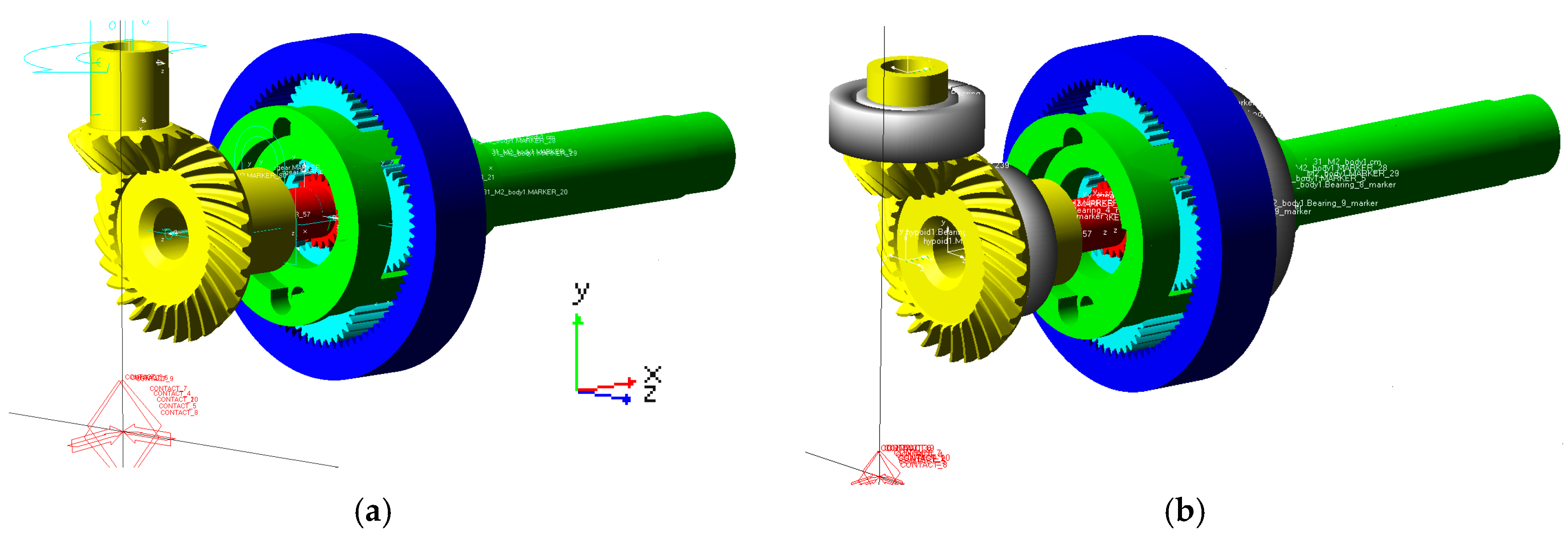
This study first utilizes KISSsoft software (Version 2018) to generate high-precision 3D tooth profile models for the spiral bevel gear set and planetary gear train based on actual gear design parameters. These models are then imported into ADAMS software (Version 2018) to establish a multibody dynamics simulation model of the combined reducer, as shown in Figure 2. The inherent backlash in the 3D tooth profiles enables accurate simulation of backlash effects during the gear meshing process. First, disregarding system bearings, all rotational axes are modeled as revolute joints to establish the multi-rigid-body dynamics model of the combined reducer, as shown in Figure 2a. Here, the input/output axes align with Y/X axes, respectively, with the Z axis perpendicular to the XY plane. Second, to investigate bearing–gear coupling effects, the detailed bearing module in ADAMS is used to simulate specific bearing models, constructing the rigid–flexible coupling reducer model, as shown in Figure 2b, where some bearings are hidden for clarity of visualization. The bearing models arranged on each component are shown in Table 1, and the bearing distribution is shown in Figure 3. It should be noted that the two sets of angular contact ball bearings between the spiral bevel gear and the ground are installed back to back.
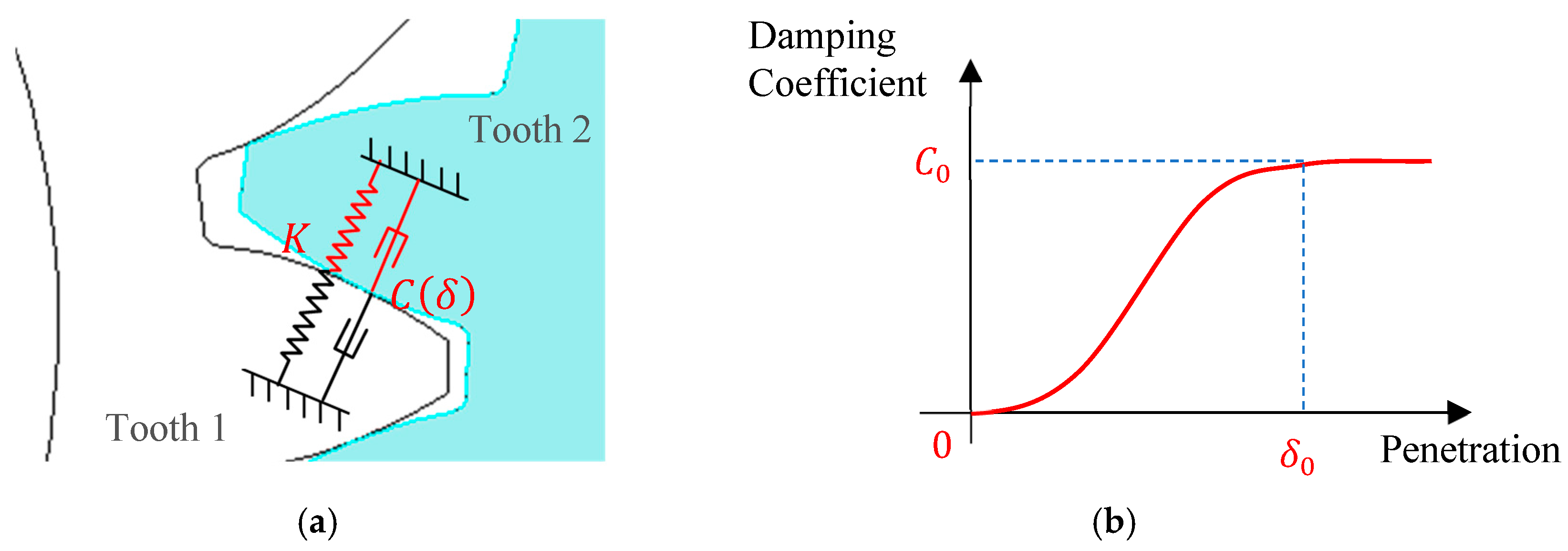
In ADAMS, the impact function is used to calculate the meshing force. The contact collision model is based on Hertz elastic impact theory, enabling accurate simulation of the input–output characteristics of gear transmission mechanisms. Figure 4a illustrates the schematic diagram of the meshing force between any gear tooth pair. The gear tooth contact force can be expressed as [26]
F = K δ e C δ δ ˙ ,
where K is the equivalent contact stiffness of the elastic meshing tooth profile; δ is the penetration at the meshing point; δ ˙ is the penetration velocity of the tooth profile; e is the nonlinear elasticity exponent. For metallic contact, this can be set to 1.5; C δ is the penetration-dependent contact damping polynomial, describing the energy loss during gear meshing. The damping coefficient curve is shown in Figure 4b, expressed as C δ = S T E P δ ,   0 ,   0 , δ 0 , C 0 . Here, δ 0 is the penetration depth at which the damping coefficient reaches its maximum value, set to 0.1 mm in this study. C 0 is the maximum damping coefficient value, typically set to 1% of the meshing stiffness [27].
The equivalent contact stiffness between gear tooth pairs can be obtained by the Hertz contact model as
K = 4 3 R 1 2 E ,
R = R 1 R 2 R 1 ± R 2 ,
1 E = 1 μ 1 2 E 1 + 1 μ 2 2 E 2 ,
where R 1 and R 2 denote the equivalent radii of curvature for the two meshing gears at the meshing point (‘+’ for external meshing, ‘−’ for internal), μ 1 and μ 2 represent the Poisson’s ratios of the gear materials, and E 1 with E 2 are their respective elastic moduli.

3. Multi-Rigid-Body Model Dynamics Analysis

3.1. Meshing Theory

Assuming that the input angular velocity is N 1 (Unit: r/min), the meshing frequency of the spiral bevel gear pair is
f s = Z 1 N 1 60 .
The meshing frequency of the planetary gear train is
f p = Z 5 N 6 60 ,
where N 6 is the angular velocity of the carrier, which also is the output angular velocity of the combined reducer.
Assume that the force acting point is located at the indexing circle of the spiral bevel gear tooth width center, and the meshing tangential force is
F m t = 2000 T 1 d m 1 = 2000 T 2 d m 2 ,
where T 1 , T 2 are the transmitted torques of gear 1 and gear 2, respectively; d m 1 , d m 2 are the pitch diameters of gear 1 and gear 2, respectively.
The spiral direction is left-handed for both hypoid pinion 1 and wheel 2. Their meshing force components can be resolved into radial and axial vectors as [28]
F r 1 = F a 2 = F m t tan α n cos β h cos δ 1 tan β h sin δ 1 ,
F r 2 = F a 1 = F m t tan α n cos β h sin δ 1 ± tan β h cos δ 1 ,
where F r 1 and F r 2 denote radial meshing forces for pinion 1 and wheel 2; F a 1 and F a 2 represent axial meshing forces; δ 1 is the shaft angle of pinion 1; α n , β h are the pressure angle and the spiral angle of the bevel gear pair. The radial and axial meshing force of the spiral bevel gear are related to the input rotation direction. When hypoid pinion 1 rotates clockwise, Equation (9) takes a negative sign, while Equation (10) takes positive sign.
For the planetary gear train, when the torque is input from sun gear 3, the tangential force of external meshing (sun gear to planetary gear) and internal meshing (planetary gear to ring gear) are the same and can be expressed as
F t 3 = 2 T 3 C 4 d 3 ,
where T 3 is the input torque of gear 3; C 4 is the number of planetary gears; d 3 is the pitch circle diameter of sun gear 3.

3.2. Simulation Results Analysis

Undoubtedly, the rigid–flexible coupling model with bearings produces more realistic results than the multi-rigid-body model. However, the basic theoretical calculation in Section 3.1 is based on the ideal situation and ignored bearings, making the multi-rigid-body model better suited for theoretical validation. Therefore, this study first compares multi-rigid-body simulations against theoretical results.
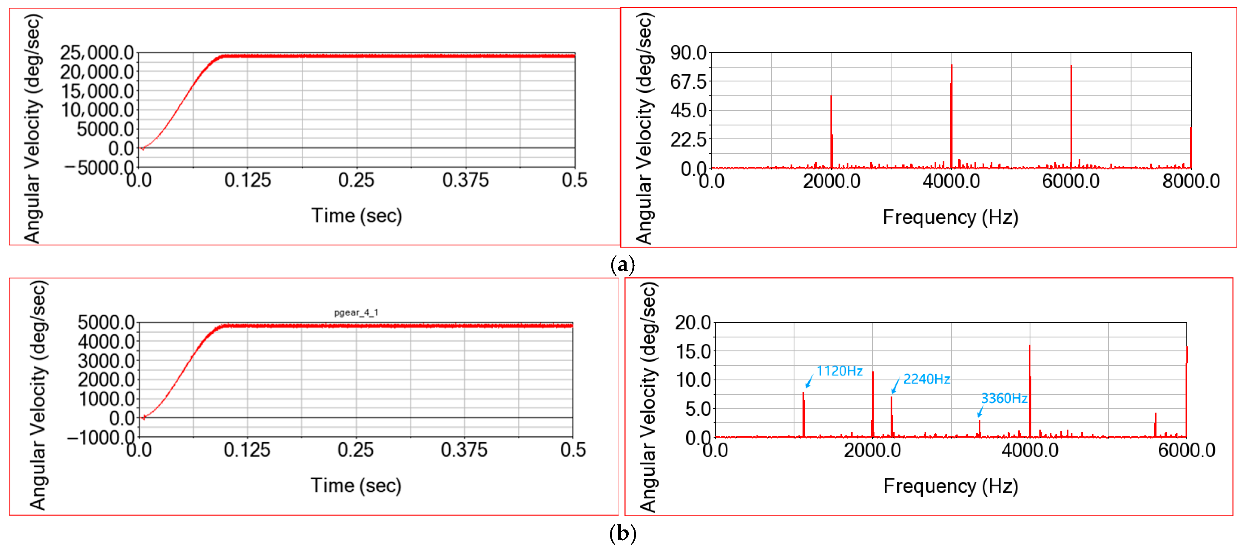
Dynamic simulation of the multi-rigid-body model yields output speeds for wheel 2 and carrier 6, as shown in Figure 5. The input angular velocity of pinion 1 is N 1 = 8000   r / m i n = 48000   ° / s , and input torque is T 1 = 4   N m . To avoid the impact caused by a sudden change in angular velocity during simulation, the input velocity and torque are added by the STEP function in ADAMS. The parameters of each gear in the combined reducer are shown in Table 2.
Figure 5 shows output angular velocities of 4000 r/min for wheel 2 and 800 r/min for the planetary carrier 6, yielding a simulated transmission ratio of 10, which is fully consistent with the theoretical values, thereby validating the model’s accuracy. Additionally, gear meshing induces angular velocity fluctuations. Wheel 2’s velocity spectrum exhibits the spiral bevel gear meshing frequency and its harmonics, while the carrier’ s fluctuations contain both spiral bevel and planetary gear meshing frequencies, confirming the rotational energy transfer pathway.
Figure 6 displays the time domain meshing force and frequency distribution for the spiral bevel gear pair. Under clockwise hypoid pinion rotation, X/Y/Z force projections correspond to axial, radial, and tangential components of hypoid pinion 1, respectively. The definitions of each direction are shown in Figure 2. The simulation average values of tangential meshing force and radial force are 454 N and 383 N, respectively, which have only errors of 1.08% and 1.37% compared to the theoretical meshing force from Equations (8)–(10). The simulation average value of axial force is 43 N, and the error compared to the theoretical value is 10%, which is greater than the tangential force and axial force error. In addition, it can be seen from the frequency domain distribution of meshing force that the dominant amplitude peaks are mainly gear meshing frequency and its frequency multiplication, which is one of the main sources of vibration of planetary gear reducers. There are amplitude modulation sidebands on both sides of the meshing frequency, which is consistent with the previous research results [24]. In addition to the gear meshing frequency, the amplitude–frequency curve also contains some small peaks caused by meshing impact.
Figure 7 presents the time domain internal/external meshing forces and corresponding frequency distribution for the planetary gear train. The synchronous fluctuation patterns of both meshing forces align with theoretical predictions. The simulated average values of internal and external meshing force are 334 N and 341 N, respectively, with errors of 0.8% and 1.1% compared to the theoretical meshing force, which verifies the accuracy of the ADAMS model. As shown in the meshing force amplitude–frequency curve, the meshing force fluctuation frequency is mainly the gear meshing frequency of the planetary gear train and its frequency multiplication; meanwhile, it is also slightly affected by the meshing frequency of the spiral bevel gear pair.
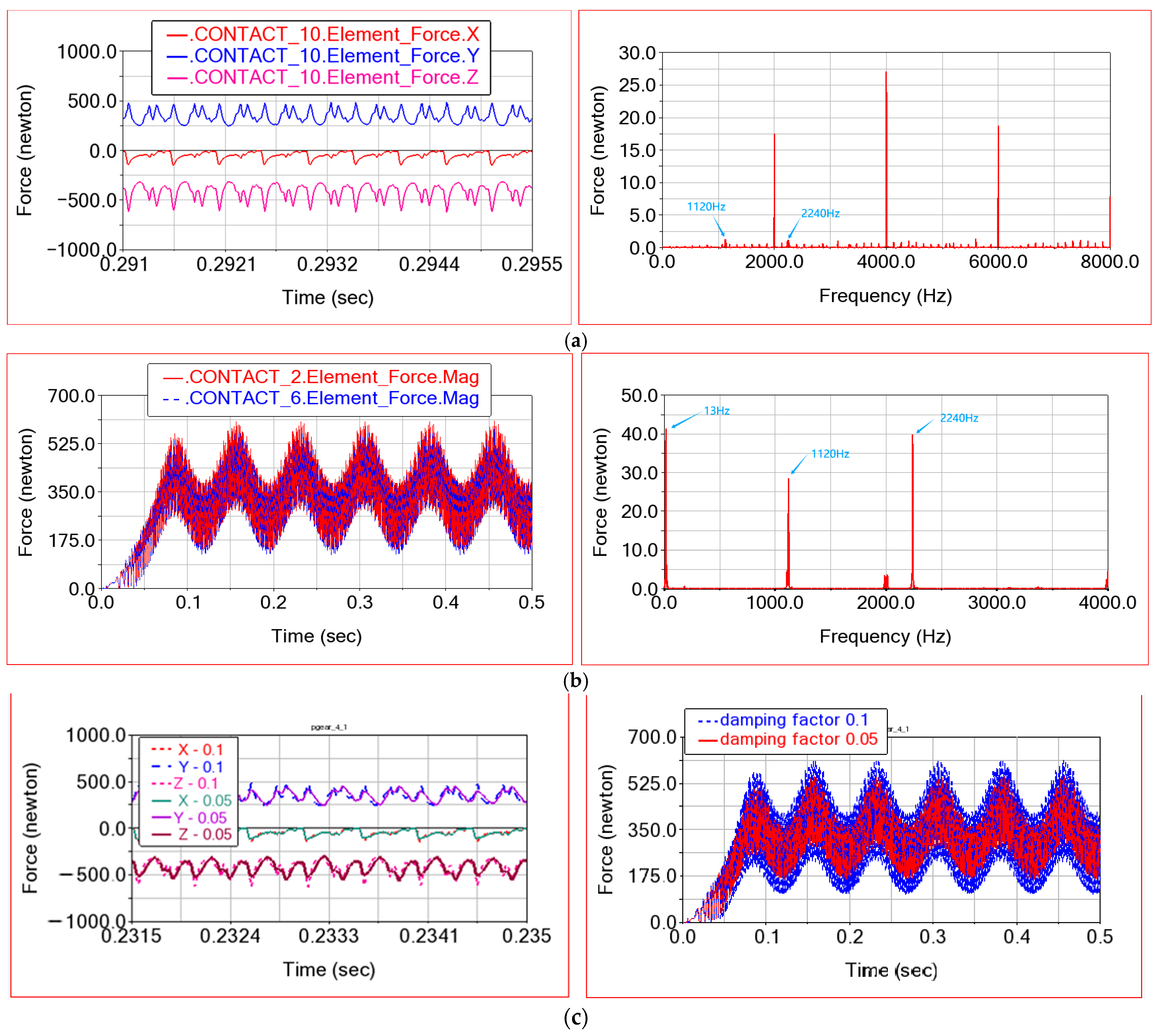
Figure 8 displays time domain meshing forces and frequency distributions for the rigid–flexible coupling ADAMS model. As can be seen from Figure 8a, due to the existence of the flexible bearing module, the meshing force of the spiral bevel gear pair is smoother, and the resonance peak at the meshing frequency and its frequency multiplication is reduced. In addition, the peak value of the amplitude–frequency curve caused by meshing impact is also obviously reduced. When flexible bearings are included, the planetary gear train and the spiral bevel gear pair are more integrated, and the meshing force fluctuation of the spiral bevel gear pair also includes the meshing frequency of the planetary gear train. As can be seen from Figure 8b, the fluctuation in the internal and external meshing force of the planetary gear train is quite different from that of the multi-rigid-body model. Firstly, the meshing frequency of the planetary gear train and its peak response at frequency multiplication is reduced. Secondly, the system contains an obvious low-frequency fluctuation, which is the rotation frequency of the planetary carrier. This low-frequency fluctuation greatly increases the maximum meshing force and the fluctuation range of meshing force, which will make the gear more prone to fatigue and reduce the reliability of the reducer. The reason is that after adding the six-degree-of-freedom bearing module, the axis of the sun gear and the planet carrier will not always remain parallel to the X axis during the meshing process but will shift, and this coupling effect will be analyzed in detail in the next section.
Furthermore, Figure 8c illustrates the influence of bearing damping factors on meshing forces. As the bearing damping factor decreases, both spiral bevel gear and planetary gear sets exhibit reduced meshing force amplitudes. This amplitude reduction stems from the complex nonlinear relationship between meshing forces and damping factors. However, low-frequency fluctuations in planetary gear meshing forces persist regardless of damping factor variations. As a result, while bearing damping factors affect gears’ fatigue life by altering dynamic meshing force magnitudes, they cannot eliminate the low-frequency fluctuations induced by flexible bearings in planetary gear trains. Thus, this study focuses primarily on analyzing coupled gear–bearing interactions affecting dynamic meshing forces in the combined reducer.

4. Motion Coupling Analysis

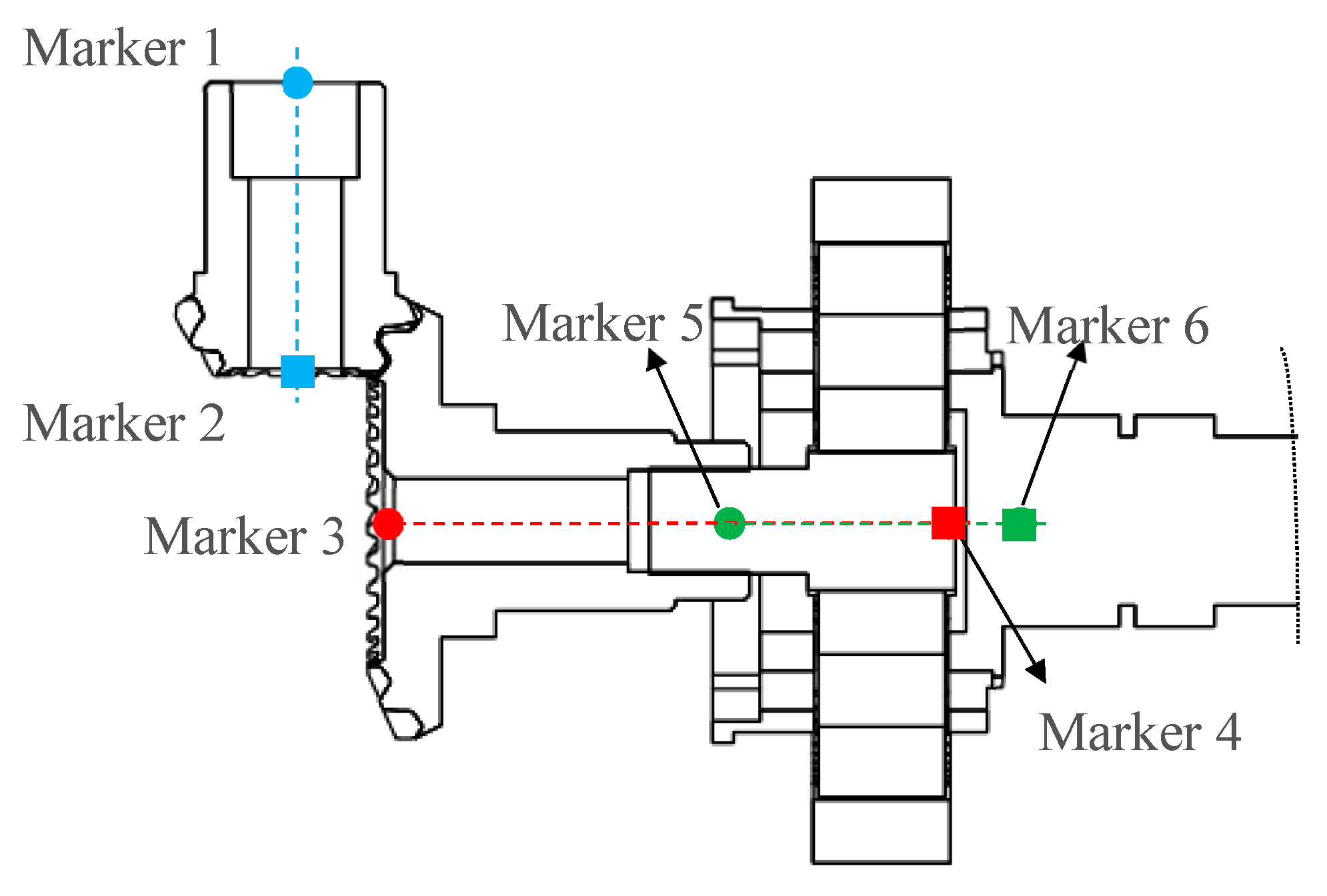
As shown in Figure 9, to analyze the coupled gear–bearing interaction effects on meshing force dynamics in the combined reducer, marker points are defined at the endpoints of each gear shaft, leveraging the rigid-body assumption for gears and shafts. By monitoring displacement at these markers during the system’s operation, the geometric spatial states of gear axes are captured, enabling investigation of bearing-induced deflection vibration effects on gear shafts and exploration of bearing-influenced gear meshing force fluctuation mechanisms. Specifically, markers 1–2 represent the hypoid pinion 1 axis (input shaft), markers 3–4 correspond to the hypoid gear 2 and sun gear shared axis, and markers 5–6 denote the planet carrier axis.
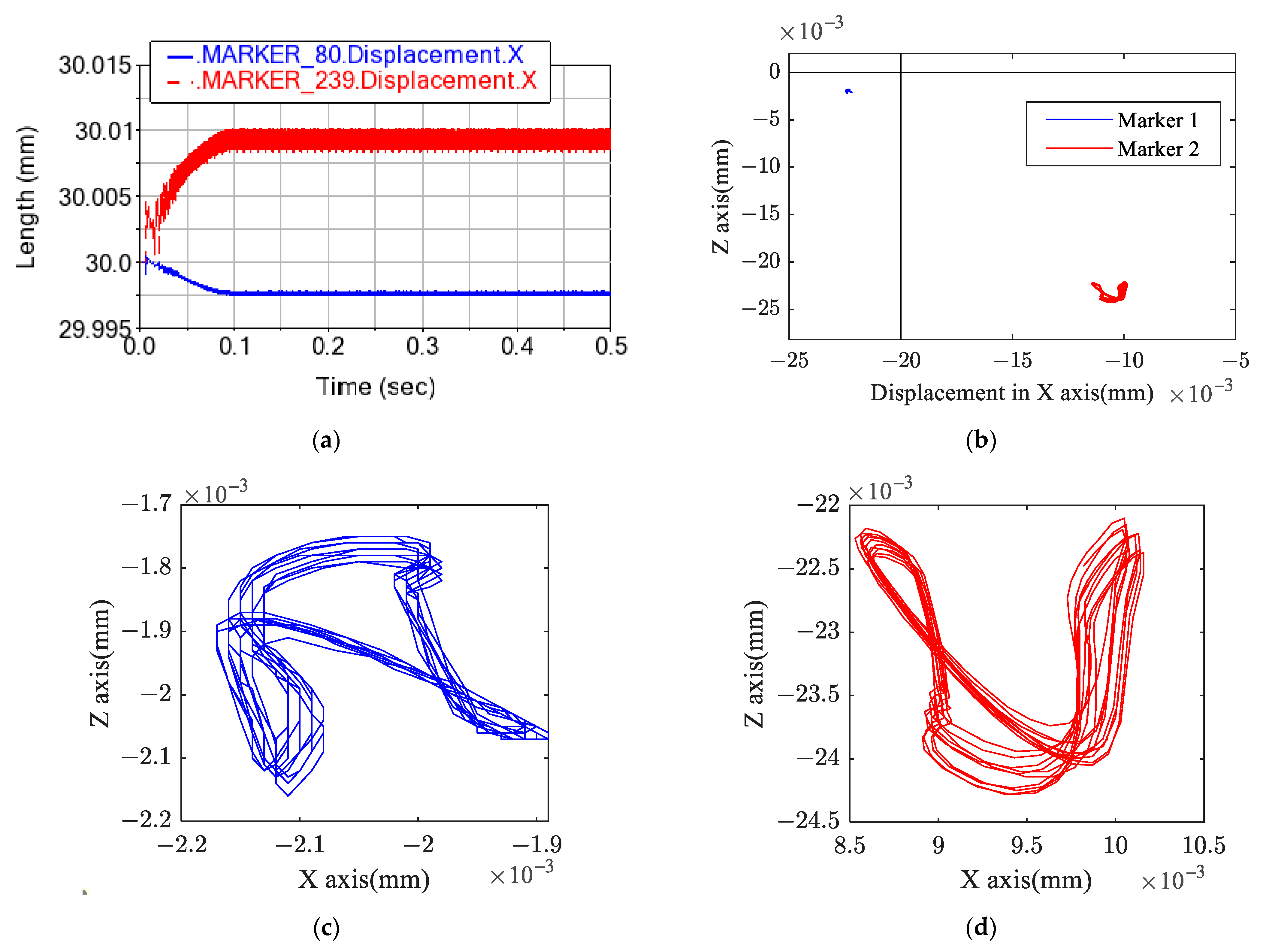
Figure 10 presents time domain displacements and spatial trajectories of marker 1 and marker 2. It can be seen that both input shaft ends are displaced in the XZ plane due to the existence of flexible bearings. As shown in Figure 10a, marker 1 and marker 2 are displaced from the initial state during stable operation, wherein the displacement of marker 2 is greater than that of marker 1, and the displacements of these markers are not constant but fluctuate. Figure 10b shows the spatial displacement of marker 1 and marker 2, here takes the initial position as the coordinate origin. It can be seen that under the action of gear meshing force, hypoid pinion 1 moves in the negative direction of the Z axis, resulting in a trend of disengagement, which reduces the meshing force. It should be noted that during the meshing of the spiral bevel gear pair, wheel 2 gives spiral pinion 1 an attractive force, which makes marker 2 move towards the positive direction of the X axis. The displacement of marker 1 in the XZ plane is much smaller than that of marker 2; that is, the end of the input shaft near the meshing position has a greater displacement, and its swing amplitude is greater. The axis of the input shaft swings continuously during operation, which will further cause the reducer to vibrate. At this time, the vibration frequency in the system will not only include the gear meshing frequency but also include the obvious input shaft swing frequency. As shown in Figure 10c,d, the vibration trajectories at both ends of the input shaft are symmetrical, which is because the input shaft body is rigid, and the swing at both ends is caused by the coupling motion of gears and six-degree-of-freedom angular contact ball bearings.
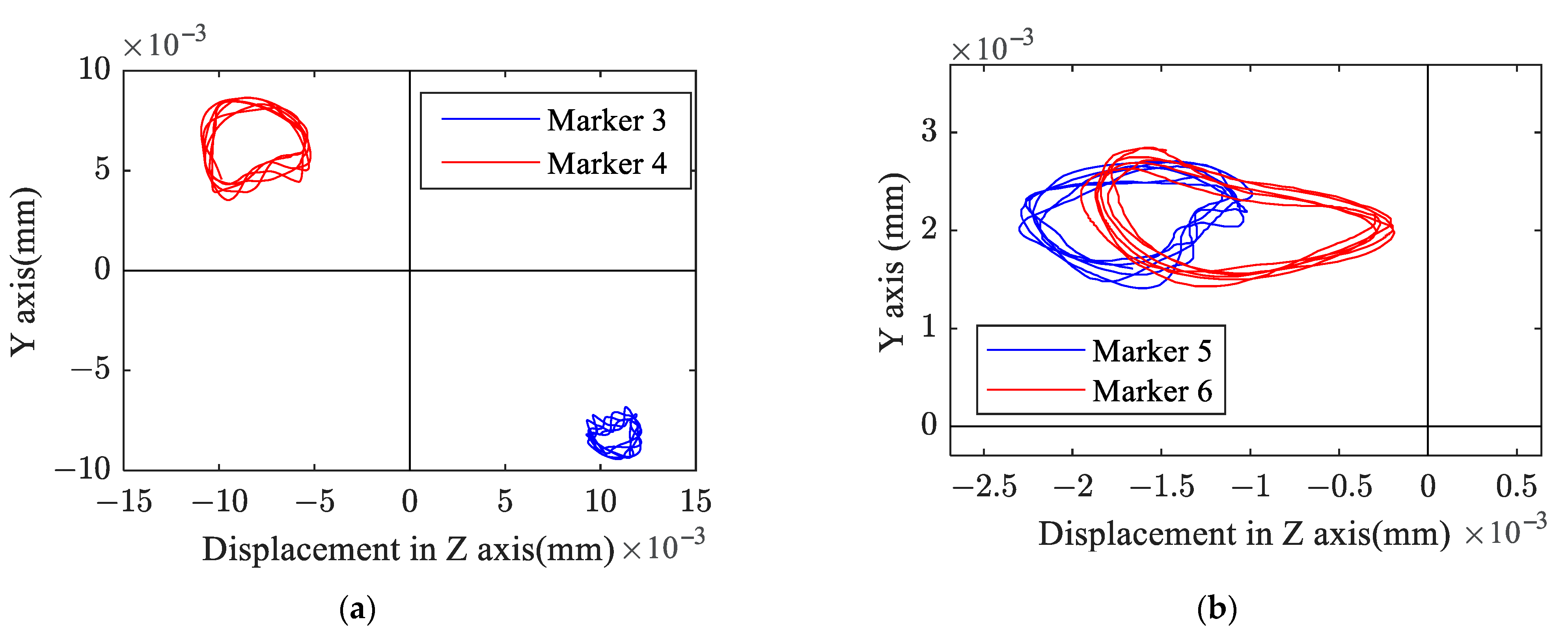
Figure 11 shows the spatial geometric states of the sun gear axis and the planet carrier axis. Here, the initial state is also taken as the coordinates’ origin. As can be seen from Figure 11a, hypoid wheel 2 and the sun gear axis have a great swing in the YZ plane. The average displacement of marker 3 (hypoid gear end) is larger than that of marker 4 (sun gear end), but the swing amplitude of marker 3 is smaller. It is worth noting that hypoid pinion 1 deviates in the negative direction of the Z axis at the meshing point, but hypoid wheel 2 deviates in the positive direction of the Z axis; that is, the two hypoid gears tend to disengage, which reduces the meshing force. In addition, the sun gear’s displacement (marker 4) is opposite to the displacement of hypoid wheel 2 (marker 3), which has a deviation in the positive direction of the Y axis and the negative direction of the Z axis. As can be seen from Figure 11b, the two ends (marker 5 and marker 6) of the planet carrier are offset in the positive direction of the Y axis and the negative direction of the Z axis at the same time; meanwhile, the offset displacement and amplitude are not much different.
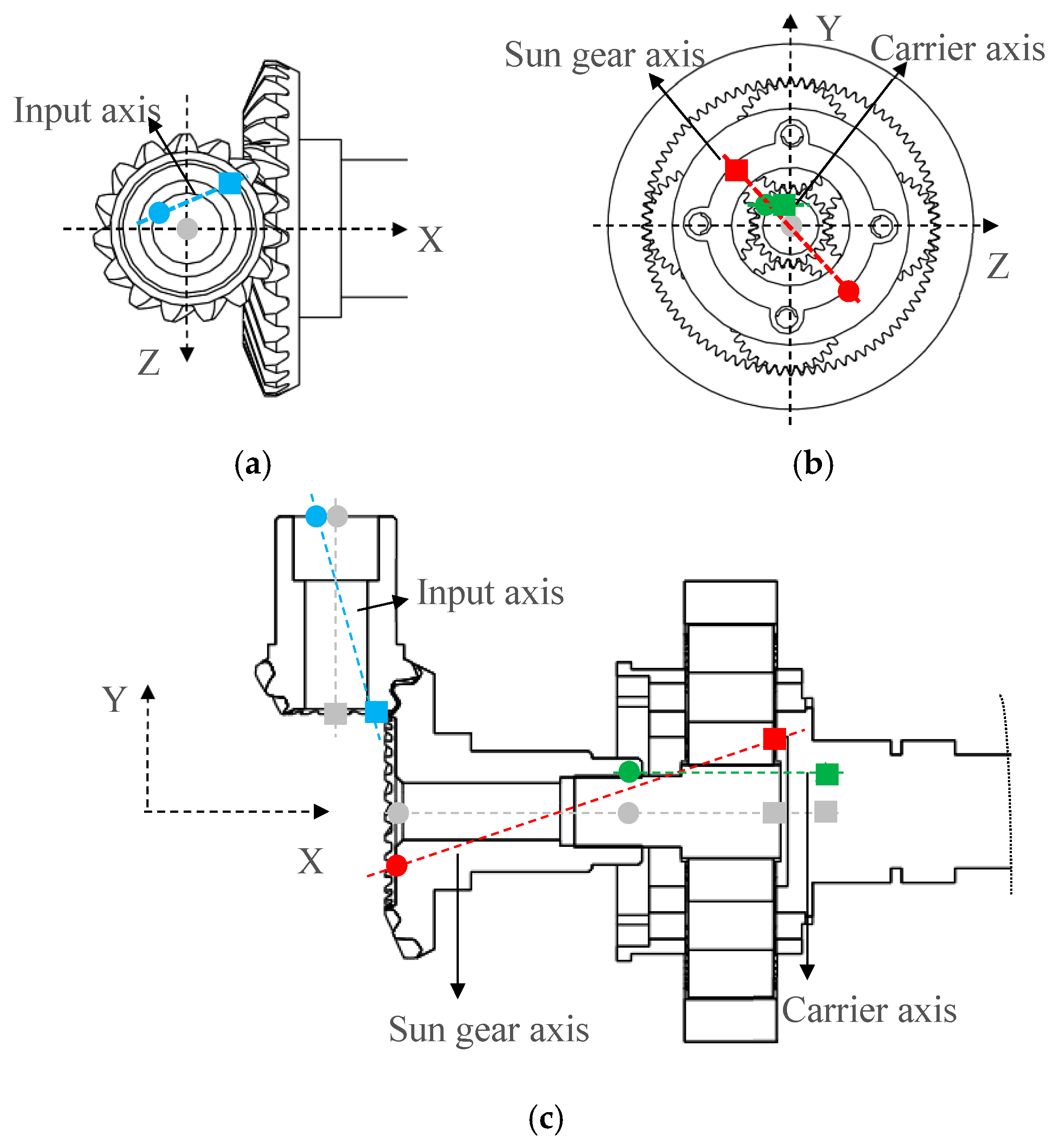
Figure 12 shows the projection of the axial space state of each component across orthogonal planes. It should be noted that the actual displacement of each marked point from the initial state is extremely small, necessitating magnified representations in Figure 12 for clear visualization of axis kinematics. Referring to Figure 12, the coupling motion of the combined gear reducer under the coupling effect of gear and flexible bearing can be summarized. Firstly, the meshing force between hypoid pinion 1 and hypoid wheel 2 takes them far away from each other in the Z direction, and both the input axis and sun gear axis oscillate due to the existence of angular contact ball bearings. The deviation of hypoid wheel 2 from its initial position will make the sun gear shift to the opposite direction. The shifting of the sun gear (marker 4) will further drive the planetary gear and the planet carrier to shift together, with the result that the rotation center of the planetary gear train is not at its geometric center. Consequently, a low-frequency periodic fluctuation occurs during planetary gear engagement with either the sun gear or ring gear. In other words, when planetary gear 4 positions itself where clearance between sun gear 3 and ring gear 5 narrows, the internal and external meshing forces within the planetary train intensify. On the contrary, reduced meshing forces manifest at wider clearance positions. This low-frequency fluctuation demonstrably corresponds to the planet carrier’s rotational frequency.
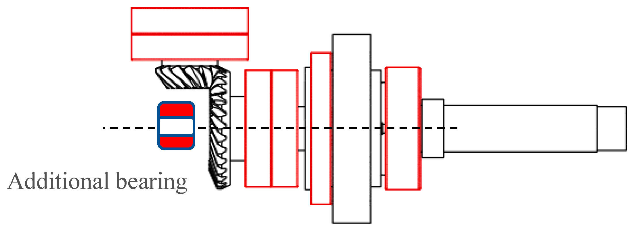
Overall, comparative analysis between the multi-rigid-body model and rigid–flexible coupling model of the combined reducer reveals that gear–bearing coupling induces significant low-frequency fluctuations in planetary gear meshing forces, increasing the maximum value and fluctuation amplitude of meshing force, which accelerate gear fatigue failure. This phenomenon originates from displacement of hypoid gear 2 (marker 3) under meshing loads, exacerbated by its cantilever configuration (as shown in Figure 1). To suppress the low-frequency fluctuation in meshing force, the offset of hypoid wheel 2 should be controlled, and an effective method is by adding a bearing at the end of hypoid wheel 2 to eliminate its cantilever characteristics, as shown in Figure 13.
Figure 14 presents the planetary gear train’s time domain meshing force and corresponding frequency domain distribution following implementation of an added bearing, with, specifically, model INA-BK0810 (ADAMS machinery module) in the simulation. It should be noted that the function of the additional bearing is eliminate cantilever shaft effects in hypoid gear 2. Through comparative analysis of meshing force fluctuations versus without this bearing, the vibration suppression efficacy of the optimized bearing arrangement can be demonstrated. Therefore, the additional bearing’s selection can be flexibly adapted to volume constraints in reducer design. As shown in Figure 14, the maximum internal and external meshing forces are 515 N and 540 N, respectively, after adding an additional bearing, which is lower than that without an additional bearing. In addition, the low-frequency fluctuation in meshing force decreases greatly, but the peaks at meshing frequency and its multiplication increase. Nevertheless, the maximum internal and external meshing force of the planetary gear train is still smaller than that of the multi-rigid-body model. The reason why the amplitude of low-frequency fluctuation in meshing force decreases is that the offset distance of hypoid wheel 2 is constrained by the additional bearing, as shown in Figure 15. Table 3 shows the change in the average displacement of markers 1~4 after adding an additional bearing. It can be seen that after adding the bearing, the displacement deviation of sun gear axis (marker 3 and marker 4) is reduced, thus reducing the maximum value and fluctuation range of the internal and external meshing force, which is beneficial to improving the reliability of the planetary gear reducer. It is worth noting that the offset displacement of the input shaft persists unaltered after adding the bearing, maintaining prominent swing frequency components in the vibration spectra of the combined reducer.

5. Experimental Verification

To verify the accuracy of the coupling effect analysis of gear meshing and flexible bearings, experimental vibration testing is performed on the combined reducer prototype. As shown in Figure 16, the test setup includes the gear reducer with an additional bearing and a controlled test bench regulating input angular velocity and torque. Vibration signals are acquired using a tri-axial accelerometer (PCB Piezotronics model 356A16, Depew, NY, USA, sensitivity: 99.6 mV/g, range: ±50 g) sampled at 4000 Hz through an NI-9234 data acquisition system. Signal processing is performed using M + P SO analyzer software (Revision 3.0), where frequency domain distributions are obtained via FFT with application of a Hanning window to mitigate spectral leakage and aliasing effects.
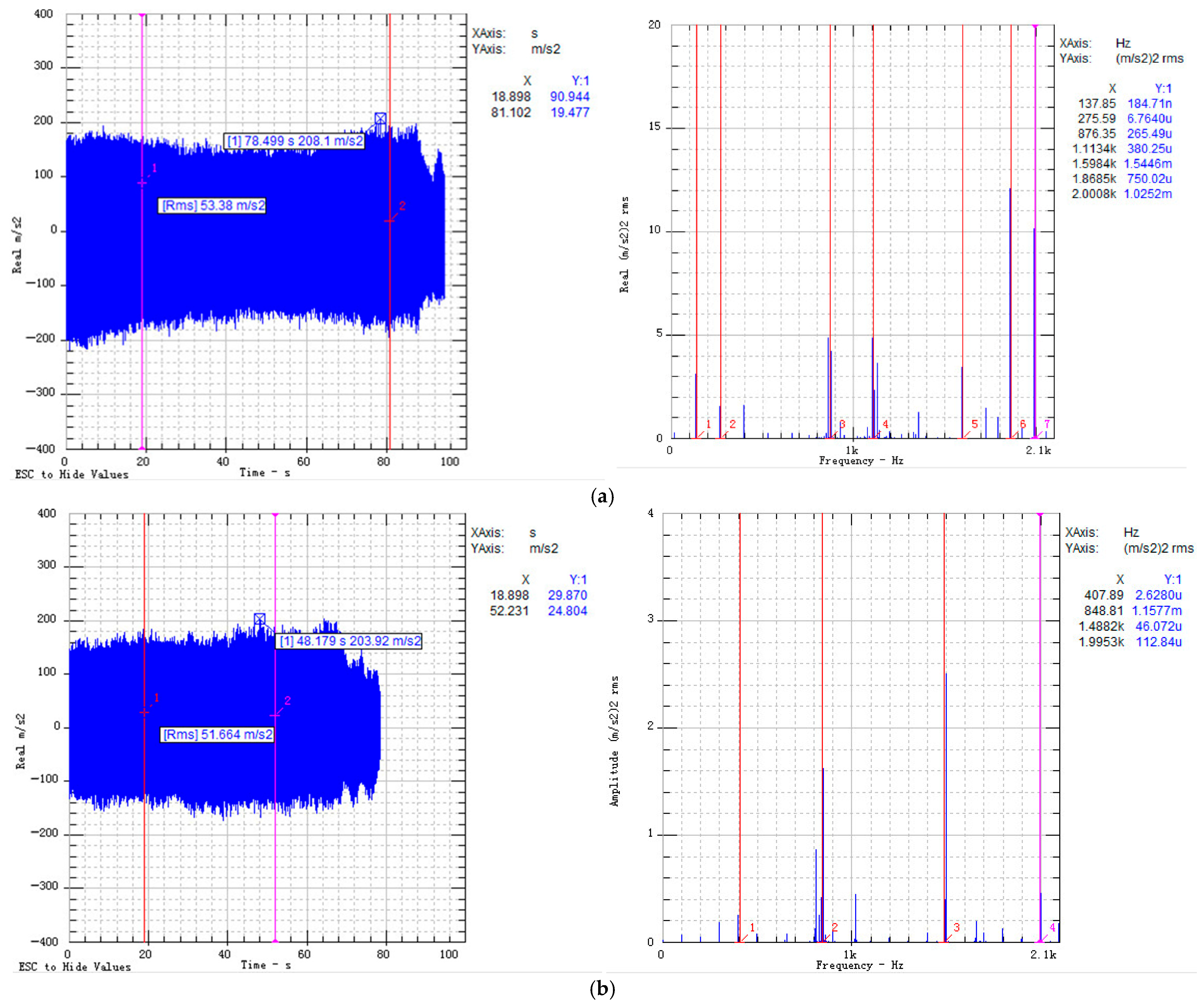
Figure 17 presents the prototype’s time domain vibration acceleration and corresponding frequency domain distributions at input speeds of 8000 r/min and 6000 r/min. At 8000 r/min, predominant frequencies include 137 Hz, 275 Hz, 876 Hz, 1113 Hz, 1598 Hz, 1868 Hz, and 2008 Hz. Here, 1113 Hz and 2008 Hz align with the planetary (theoretical 1120 Hz) and hypoid gear (theoretical 2000 Hz) meshing frequencies, respectively. Components at 1598 Hz and 1868 Hz correspond to the test bench’s natural frequency, while 137 Hz and 275 Hz represent input shaft swing frequencies (theoretical 133.3 Hz). At 6000 r/min, significant frequencies comprise 100 Hz, 200 Hz, 300 Hz, 400 Hz, 848 Hz, and 1488 Hz, where 848 Hz and 1488 Hz match the planetary (theoretical 850 Hz) and hypoid (theoretical 1500 Hz) meshing frequencies, respectively. The frequency components at 100 Hz and its harmonics reflect the input shaft rotation frequency. As a result, there is an obvious vibration component at the input shaft rotation frequency in the test, but output shaft rotation components are not obvious, which verifies the coupling effect between gear meshing and bearing in this paper. The swing of the output shaft will be suppressed by the additional bearings, and the vibration spectra of the combined reducer will include the gear meshing frequency and input shaft swing frequency.

6. Conclusions

This study establishes a multibody dynamic model for the coupled spiral bevel–planetary gear system and investigates bearings’ influences on system dynamics. Theoretical calculations of rotational speeds and meshing forces align with multi-rigid-body simulation results, validating the model’s integrity. Gear meshing induces angular velocity fluctuations in the combined reducer output, with dominant spectral components at gear meshing frequencies and their harmonics. Meshing force fluctuations in both spiral bevel and planetary trains constitute the primary vibration source.
The existence of flexible bearings in the rigid–flexible coupled model results in the minimal component displacements during meshing and induces significant input shaft oscillation, amplifying the overall reducer vibration. Sun gear displacement further triggers low-frequency meshing force fluctuations synchronized with carrier rotation, which increases the maximum dynamic meshing force of the planetary gear train and is not conducive to its fatigue life. This low-frequency fluctuation can be greatly reduced by introducing additional bearings. In addition, dynamic testing confirms that vibration spectral components include obvious shaft rotation frequencies except gear meshing frequencies, verifying the modeling accuracy and analytical methodology.
The scientific novelty of this work lies in revealing the influence of bearings on gear mesh vibration and meshing force fluctuation within the spiral bevel–planetary combined reducer, along with elucidating the underlying mechanisms. This provides critical guidance for optimizing bearing arrangement designs in combined reducers during practical engineering, ultimately mitigating gear tooth meshing vibrations and enhancing fatigue life.

Author Contributions

Conceptualization, F.L.; Methodology, F.L.; Software, C.Y.; Validation, C.Y.; Formal analysis, F.L.; Investigation, C.Y.; Resources, J.Z.; Writing—original draft, F.L.; Writing—review & editing, C.Y.; Visualization, C.Y.; Supervision, J.Z.; Project administration, J.Z.; Funding acquisition, J.Z. All authors have read and agreed to the published version of the manuscript.

Funding

The National Key Research and Development Program of China (Grant No. 2019YFB2006402).

Data Availability Statement

The data presented in this study are available on request from the corresponding author.

Conflicts of Interest

The authors declare that they have no conflicts of interest or financial conflicts to disclose.

References

  1. Dinh, H.T.; Pham, V.T.; Pham, Q.H. Spiral Bevel Gear Manufacturing Technology: A Review. In Proceedings of the 3rd Annual International Conference on Material, Machines and Methods for Sustainable Development (MMMS2022), Can Tho, Vietnam, 10–November 2022; Springer: Cham, Switzerland, 2024. [Google Scholar] [CrossRef]
  2. Penaud, J.; Alazard, D.; Amiez, A. Kinematic Analysis of Spatial Geared Mechanisms. ASME J. Mech. Des. 2012, 134, 021009. [Google Scholar] [CrossRef]
  3. ISO 6336-1:2019; Calculation of Load Capacity of Spur and Helical Gears—Part 1: Basic Principles, Introduction and General Influence Factors. International Organization for Standardization: Geneva, Switzerland, 2019.
  4. Yousfi, N.; Zghal, B.; Akrout, A.; Walha, L.; Haddar, M. Damping models identification of a spur gear pair. Mech. Mach. Theory 2018, 122, 371–388. [Google Scholar] [CrossRef]
  5. Walha, L.; Fakhfakh, T.; Haddar, M. Nonlinear dynamics of a two-stage gear system with mesh stiffness fluctuation, bearing flexibility and backlash. Mech. Mach. Theory 2009, 44, 1058–1069. [Google Scholar] [CrossRef]
  6. Kim, W.; Lee, J.Y.; Chung, J. Dynamic analysis for a planetary gear with time-varying pressure angles and contact ratios. J. Sound Vib. 2012, 331, 883–901. [Google Scholar] [CrossRef]
  7. Sondkar, P.; Kahraman, A. A dynamic model of a double-helical planetary gear set. Mech. Mach. Theory 2013, 70, 157–174. [Google Scholar] [CrossRef]
  8. Chaari, F.; Fakhfakh, T.; Haddar, M. Dynamic analysis of a planetary gear failure caused by tooth pitting and cracking. J. Fail. Anal. Prev. 2006, 6, 73–78. [Google Scholar] [CrossRef]
  9. Hu, Y.; Li, G.; Zhu, W.; Cui, J. An Elastic Transmission Error Compensation Method for Rotary Vector Speed Reducers Based on Error Sensitivity Analysis. Appl. Sci. 2020, 10, 481. [Google Scholar] [CrossRef]
  10. Jiang, N.; Wang, S.; Yang, A.; Zhou, W.; Zhang, J. Transmission Efficiency of Cycloid–Pinion System Considering the Assembly Dimensional Chain. Appl. Sci. 2022, 12, 11917. [Google Scholar] [CrossRef]
  11. Huang, K.; Cheng, Z.; Xiong, Y.; Han, G.; Li, L. Bifurcation and chaos analysis of a spur gear pair system with fractal gear backlash. Chaos Solitons Fractals 2021, 142, 110387. [Google Scholar] [CrossRef]
  12. Yang, J.J.; Shi, Z.H.; Zhang, H.; Li, T.X.; Nie, S.W.; Wei, B.Y. Dynamic analysis of spiral bevel and hypoid gears with high-order transmission errors. J. Sound Vib. 2018, 417, 149–164. [Google Scholar] [CrossRef]
  13. Gosselin, C.; Cloutier, L.; Nguyen, Q. A general formulation for the calculation of the load sharing and transmission error under load of spiral bevel and hypoid gears. Mech. Mach. Theory 1995, 30, 433–450. [Google Scholar] [CrossRef]
  14. Yang, X.; Song, C.; Zhu, C.; Liang, C. Impacts of Misalignments on Mesh Behaviors of Face-Hobbed Hypoid Gear Considering System Deformation. IEEE Access 2019, 7, 1. [Google Scholar] [CrossRef]
  15. Yassine, D.; Ahmed, H.; Lassaad, W.; Mohamed, H. Effects of gear mesh fluctuation and defaults on the dynamic behavior of two-stage straight bevel system. Mech. Mach. Theory 2014, 82, 71–86. [Google Scholar] [CrossRef]
  16. Lafi, W.; Djemal, F.; Tounsi, D.; Akrout, A.; Walha, L.; Haddar, M.B.J. Dynamic modelling of differential bevel gear system in the presence of a defect. Mech. Mach. Theory 2019, 139, 81–108. [Google Scholar] [CrossRef]
  17. Mu, Y.; He, X. Design and dynamic performance analysis of high-contact-ratio spiral bevel gear based on the higher-order tooth surface modification. Mech. Mach. Theory 2021, 161, 104312. [Google Scholar] [CrossRef]
  18. Temirkhan; Amrin, A. Computerised analysis of non-conjugate spiral bevel gear mesh using an advanced and fast-converging tooth contact model. Sci. Rep. 2025, 15, 25833. [Google Scholar]
  19. Song, J.; Wang, Y.; Hou, L.; Zhang, T.; Zhang, M.; Zhang, Z.; Jiang, Y.; Chen, Y.; Lin, R.; Chen, Y.S. Reliability analysis of gear-bearing drive systems considering gear manufacturing and installation errors. Sci. Rep. 2025, 15, 23301. [Google Scholar] [CrossRef] [PubMed]
  20. Zhu, H.M.; Chen, W.; Zhu, R.; Gao, J.; Liao, M. Modelling and Dynamic Analysis of the Spiral Bevel Gear-Shaft-Bearing-Gearbox Coupling System. Math. Probl. Eng. 2019, 2019, 9065215. [Google Scholar] [CrossRef]
  21. Saxena, A.; Chouksey, M.; Parey, A. Measurement of FRFs of coupled geared rotor system and the development of an accurate finite element model. Mech. Mach. Theory 2018, 123, 66–75. [Google Scholar] [CrossRef]
  22. Yavuz, S.D.; Saribay, Z.B.; Cigeroglu, E. Nonlinear time-varying dynamic analysis of a spiral bevel geared system. Nonlinear Dyn. 2018, 92, 1901–1919. [Google Scholar] [CrossRef]
  23. Mohamme, O.D.; Rantatalo, M.J.O. Aidanpääc. Dynamic modelling of a one–stage spur gear system and vibration–based tooth crack detection analysis. Mech. Syst. Signal Process. 2015, 54, 293–305. [Google Scholar] [CrossRef]
  24. Han, H.Z.; Zhang, S.H.; Yang, Y.; Ma, H.; Jiang, L. Modulation sidebands analysis of coupled bevel gear pair and planetary gear train system. Mech. Mach. Theory 2022, 176, 104979. [Google Scholar] [CrossRef]
  25. He, Z.; Xing, Z.; Zhou, Q.; Chang, L.H. Dynamic Analysis of a Combined Spiral Bevel Gear and Planetary Gear Set in a Bucket Elevator with High Power Density. Sustainability 2023, 15, 4304. [Google Scholar] [CrossRef]
  26. Wang, G.; Deng, W.; Du, X.; Li, X. The Absolute Deviation Rank Diagnostic Approach to Gear Tooth Composite Fault. Shock Vib. 2017, 2017, 7285216. [Google Scholar] [CrossRef]
  27. Li, J.; Kang, B.; Sun, Y.; Huang, Y.; Guo, J.; Gao, Z. Dynamic Characteristic Analysis of the Shield Machine Three-Stage Planetary Reducer Considering Tooth Wear. J. Vib. Eng. Technol. 2024, 12, 7291–7304. [Google Scholar] [CrossRef]
  28. Vullo, V. Spiral Bevel Gears and Hypoid Gears. In Gears; Springer Series in Solid and Structural Mechanics; Springer: Cham, Switzerland, 2020. [Google Scholar] [CrossRef]
Figure 1. The transmission principle of the combined reducer of the bevel gear pair and planetary gear train.
Applsci 15 09035 g001
Figure 2. The multibody dynamic model of the combined gear reducer. (a) Rigid body model without bearings; (b) rigid–flexible coupling model with bearings.
Applsci 15 09035 g002
Figure 3. Bearing distribution of the combined gear reducer.
Applsci 15 09035 g003
Figure 4. Gear pair meshing contact force schematic. (a) Contact force; (b) damping coefficient curve.
Applsci 15 09035 g004
Figure 5. The output angular velocity and its frequency domain distribution. (a) Wheel 2; (b) carrier 6.
Applsci 15 09035 g005
Figure 6. The time domain meshing force and its frequency distribution for the spiral bevel gear pair.
Applsci 15 09035 g006
Figure 7. The time domain internal meshing force (CONTACT_6) and external meshing force (CONTACT_2) and its frequency distribution for the planetary gear train.
Applsci 15 09035 g007
Figure 8. Time domain meshing force and its frequency domain distribution for rigid–flexible coupling model. (a) Spiral bevel gear pair; (b) planetary gear train; (c) effect of damping factor.
Applsci 15 09035 g008
Figure 9. Defined marker points representing the gear axis.
Applsci 15 09035 g009
Figure 10. The time domain displacement and spatial position of marker 1 and marker 2. (a) Time domain displacement of marker 1 (MARKER_80) and marker 2 (MARKER_239); (b) spatial position; (c) marker 1 trajectory; (d) marker 2 trajectory.
Applsci 15 09035 g010
Figure 11. The spatial position of the sun gear axis and carrier axis. (a) Sun gear; (b) carrier.
Applsci 15 09035 g011
Figure 12. The projection of the axial space state in different planes. (a) XZ plane; (b) YZ plane; (c) XY plane.
Applsci 15 09035 g012
Figure 13. The additional bearing at the end of hypoid wheel 2.
Applsci 15 09035 g013
Figure 14. The time domain meshing force of the planetary gear train with an additional bearing and its frequency domain distribution.
Applsci 15 09035 g014
Figure 15. Displacement comparison of marker 1 in Z direction with and without additional bearing.
Applsci 15 09035 g015
Figure 16. Vibration test system of combined reducer.
Applsci 15 09035 g016
Figure 17. The time domain vibration acceleration signal and its frequency domain distribution for the prototype under different input speeds: (a) 8000 r/min; (b) 6000 r/min.
Applsci 15 09035 g017
Table 1. Bearing parameters of the combined reducer.
Installation PositionGear 1Gear 2Gear 4Carrier 6Carrier 6
Bearing TypeFAG-B71904FAG-B71904INA-HK0408SKF-61808SKF-6004
Ball/roller pitch diameter (mm)28.528.55.844631
Outer raceway radius (mm)2.532.53-1.693.62
Inner raceway radius (mm)2.482.48-1.663.55
Ball/roller diameter (mm)4.774.771.433.186.84
Number of balls/rollers14145248
Pressure angle (°)1515---
Effective roller length (mm)--5.5--
Table 2. The parameters of each gear in the combined reducer.
ParameterGear 1Gear 2Gear 3Gear 4Gear 5
Number of teeth1530213184
Module (mm)0.950.950.60.60.6
Pressure angle (°)2020202020
Helix angle (°)3030000
Table 3. Displacement comparison of different marker points.
Marker and DirectionDisplacement Without Additional Bearing (mm)Displacement with Additional Bearing (mm)
1-X−0.0022−0.0024
1-Z−0.0019−0.0015
2-X0.00930.0093
2-Z−0.0232−0.0236
3-Y−0.0082−0.0012
3-Z0.01070.0014
4-Y0.0062−0.002
4-Z−0.0046−0.0018
Disclaimer/Publisher’s Note: The statements, opinions and data contained in all publications are solely those of the individual author(s) and contributor(s) and not of MDPI and/or the editor(s). MDPI and/or the editor(s) disclaim responsibility for any injury to people or property resulting from any ideas, methods, instructions or products referred to in the content.