Abstract
To address the issue of key component degradation in hybrid electric commercial vehicles under complex driving cycles negatively impacting system economy and durability, this paper proposes a model predictive control (MPC)-based energy management co-optimization strategy. Firstly, dynamic degradation models for the key components are established, enabling high-fidelity characterization of component health status. Secondly, a system-level model incorporating vehicle dynamics, power battery, and electric drive motor is developed, with the degradation feedback mechanism deeply integrated. Building on this foundation, an MPC-based energy management strategy for multi-objective optimization is designed. Its core functionality lies in the cooperative allocation of power sources within a rolling horizon framework: by integrating component degradation status as critical feedback into the control loop, the strategy proactively coordinates the optimization objectives between operational economy (minimization of equivalent energy consumption) and key component durability (degradation mitigation). Simulation results demonstrate that, compared to traditional energy management strategies, the proposed strategy significantly enhances system performance while ensuring vehicle drivability: equivalent energy efficiency improves by approximately 3.5%, component degradation is reduced by up to 87%, and superior state of charge (SOC) regulation capability for the battery is achieved. This strategy provides an effective control method for achieving intelligent, long-life, and high-efficiency operation of hybrid electric commercial vehicles.
1. Introduction
With the intensification of global climate change and the ongoing energy crisis, low-carbon development has become a focal point of concern for the international community. Countries around the world have successively introduced stringent carbon emission regulations to address the environmental and economic challenges posed by greenhouse gas emissions [1]. The transportation sector, as a major source of energy consumption and carbon emissions, accounts for over 20% of global carbon emissions, placing it under significant pressure to reduce carbon output [2]. The high-emission characteristics of conventional fuel vehicles are increasingly incompatible with increasingly stringent environmental protection requirements, and the industry urgently needs to achieve a green and low-carbon transformation through technological upgrades and energy structure adjustments. New energy vehicles, with their advantages of cleanliness, high efficiency, and low carbon emissions, have become the preferred technical route for replacing traditional fuel vehicles and realizing the low-carbon transformation of the transportation sector. With the continued advancement of global “dual carbon” goals, new energy vehicles provide strong technical support and development opportunities for the coordinated development of the economy and the environment [3].
Among the various technological pathways for new energy vehicles, fuel cell vehicles demonstrate broad market prospects and application value due to their high energy density, zero emissions, and excellent cruising range [4]. The energy management strategy (EMS) of the fuel cell vehicle power system must realize dynamic and coordinated power distribution between the fuel cell and the power battery, with the core objectives of minimizing overall hydrogen consumption and effectively suppressing fuel cell performance degradation [5]. However, due to the significant nonlinear dynamic degradation characteristics of fuel cells in actual operation—such as time-varying shifts in polarization curves caused by catalyst platinum particle agglomeration and electrochemical corrosion of carbon supports in the membrane electrode assembly [6]—traditional EMS based on static polarization models cannot accurately reflect the actual health state of the stack. When there is a mismatch between the model and the real state, this can easily lead to fuel cell overload risk, resulting in a significant increase in system hydrogen consumption rate, from 6.5% to as high as 24% [7].
At present, substantial research progress has been achieved by scholars at home and abroad in the fields of fuel cell system modeling and energy management [8]. However, mainstream energy management methods are mostly based on idealized stack models and fail to fully consider the dynamic degradation behavior of the stack under varying operating environments and multi-physical field coupling [9]. This leads to a decoupling between energy distribution and stack health status, making it difficult to achieve coordinated optimization of both system efficiency and durability. Some degradation modeling approaches focus only on single influencing factors, lacking a systematic analysis of the coupled effects among electrochemistry, thermal management, structural stress, and mass transfer, thus failing to meet the high accuracy and strong robustness required by engineering applications [10].
In recent years, with the widespread application of intelligent optimization algorithms (such as model predictive control and reinforcement learning) and high-performance embedded control platforms, vehicle-level energy management strategies based on stack health status and multi-physical field coupled modeling have become a research hotspot [11]. By deeply integrating the stack degradation mechanisms with energy management strategies, dynamic and adaptive optimization of energy allocation can be achieved, effectively mitigating stack performance degradation and enhancing overall system efficiency and lifespan [12].
Previous research has extensively reviewed the application of model predictive control in hybrid and electric vehicle energy management, highlighting its ability to handle multi-objective optimization and system constraints [13,14]. However, most existing MPC strategies either employ simplified degradation models or lack real-time adaptability to health state variations under diverse driving conditions. Recent advances in deep reinforcement learning and adaptive control have demonstrated improved adaptability and robustness for fuel cell hybrid systems, but these methods often require large-scale data and entail significant computational overhead, which can limit their real-time feasibility in embedded vehicular applications. In contrast, our approach explicitly incorporates a detailed degradation model within the MPC framework, enabling predictive health-aware energy management while maintaining computational tractability. By balancing system performance, fuel cell and battery degradation, and real-time implementability, our method advances beyond conventional MPC and emerging deep learning-based controllers.
Based on the above research background, this paper focuses on a typical commercial fuel cell vehicle and systematically conducts research on multi-physical field coupled stack degradation modeling, vehicle system modeling, and energy management optimization based on model predictive control. The main innovations are as follows:
- (1)
- A stack degradation model is established under multiple operating conditions and multi-factor coupling, enabling high-precision characterization of the stack’s dynamic degradation process;
- (2)
- A vehicle-level energy management strategy based on model predictive control is proposed, incorporating stack health status feedback into the control loop to achieve coordinated optimization of energy distribution and stack longevity;
- (3)
- The superiority of the proposed method in terms of dynamic performance, economic efficiency, and stack durability is verified through simulation and comparative analysis.
This research aims to provide theoretical support and engineering methodologies for the design and optimization of energy management systems in fuel cell vehicles, thereby promoting the large-scale, intelligent, and efficient development of fuel cell vehicles.
2. Model Development
In this section, the comprehensive modeling framework for the fuel cell vehicle is established. The model encompasses the longitudinal vehicle dynamics, fuel cell system, power battery, and drive motor. This integrated system model serves as the basis for subsequent energy management strategy design and simulation analysis.
2.1. Fuel Cell Hybrid Tractor Model
This study primarily focuses on the force states of the vehicle in the driving direction and establishes a longitudinal dynamics model of the vehicle. During operation, the driving force of a fuel cell vehicle must balance various resistive forces [15]. These resistances include rolling resistance, aerodynamic drag, grade resistance, and acceleration resistance. Based on the above analysis, the vehicle dynamics equation can be expressed as follows:
The hydrogen consumption of the fuel cell is an important indicator for evaluating the economic performance of fuel cell vehicles, and it is also a key parameter for assessing the effectiveness of the overall vehicle energy management strategy [16]. The hydrogen consumption of the fuel cell is closely related to its output current and can be expressed by the following equation:
For fuel cell hybrid commercial vehicles, the power battery not only participates in energy output but also plays a crucial role in energy recuperation. This portion of energy can be considered equivalent to the energy output of the fuel cell and converted into hydrogen consumption. Therefore, in the analysis of overall vehicle energy consumption, the electrical energy output of the power battery must be taken into account [17]. To unify the evaluation criteria, this paper converts the electrical energy consumption of the power battery into equivalent hydrogen consumption, which can be calculated as follows:
Therefore, the total equivalent hydrogen consumption of the vehicle is composed of the actual hydrogen consumption of the fuel cell and the equivalent hydrogen consumption of the power battery.
2.2. Fuel Cell Model
The fuel cell model comprises two parts: the electrochemical stack model and the degradation model.
- (1)
- Electrochemical Model:
According to the output characteristic equation of the PEMFC, the output voltage of a single PEMFC can be expressed as [18]
The calculation formula for the Nernst voltage is as follows:
The activation polarization voltage of the fuel cell refers to the voltage loss that must be overcome to drive the chemical reaction between hydrogen and oxygen, which arises from the chemical energy at the cathode and anode. This activation polarization loss is particularly significant under low current conditions, and as the current density increases, the activation loss gradually decreases.
The ohmic polarization voltage mainly originates from the equivalent membrane resistance of the proton exchange membrane, as well as the impedance encountered during electron transport between the electrode and the current collector. It can be expressed as follows:
The concentration polarization loss is caused by rapid mass transport limitations, which affect the concentrations of hydrogen and oxygen at high current densities, resulting in a voltage drop. The calculation formula is as follows:
- (2)
- Degradation Model:
The current fuel cell stack performance degradation assessment models are primarily based on the static operating condition classification method proposed by Pei et al. [19], which decouples the degradation process into four standard conditions: start–stop, load change, low power, and high power. However, in practical applications, the degradation rate exhibits significant time-varying characteristics due to the coupled effects of fuel cell electrochemical mechanisms and operating conditions.
In this model, based on the experimental results of the fuel cell and in combination with the above multi-condition electrochemical analysis and operating condition analysis of the fuel cell, the overall degradation rate of the fuel cell can be calculated as follows [20]:
The calculation formulas for each component are as follows:
The degradation rates of the fuel cell under different operating conditions, as obtained from reference [21], are shown in the Table 1. The experimental degradation rates in the table represent the percentage decrease in voltage of the fuel cell at rated power as measured in the experiments.

Table 1.
Experimental degradation rate of fuel cell.
According to the fuel cell degradation model established in reference [20], the parameters are represented as follows:
Under idling conditions, the fuel cell stack primarily operates within the activation potential region, where its performance degradation mechanism is characterized by the synergistic effects of PEM chemical degradation and cathode catalyst layer structural deterioration. The chemical degradation of the PEM is mainly triggered by high-potential operating conditions: when the cell voltage approaches the open-circuit voltage, the cathode remains at a high potential, and the concentration gradient of the reactant gases drives O2 to permeate across the membrane to the anode, thereby accelerating the chemical degradation of the membrane [22]. This degradation rate can be quantified by the fluoride emission rate, as a reduction in fluoride ion concentration directly disrupts the chemical composition of the membrane and decreases its ionic conductivity.
During medium-power operation, the natural degradation phenomenon of the fuel cell becomes more pronounced. At this stage, the performance decline of the fuel cell stack is primarily influenced by ohmic losses, which originate from the total ohmic resistance within the fuel cell stack.
During high-power operation, the primary degradation mechanisms of fuel cells include local oxygen starvation, membrane flooding, and kinetic, ohmic, and mass transport losses. Local oxygen starvation occurs under high current densities when insufficient oxygen supply leads to an elevated local electrode potential, which in turn accelerates carbon support corrosion as well as the dissolution and migration of platinum particles, significantly reducing the electrochemically active surface area of the catalyst. Membrane flooding results from an excessive rate of water generation combined with inadequate water management capabilities, leading to the accumulation of liquid water in the membrane and gas diffusion layer. This accumulation impedes gas transport, further aggravating local oxygen starvation and mass transport losses.
To accurately characterize the impact mechanism of dynamic load variations on fuel cell lifespan, a dynamic degradation model based on the rate of change in current density was established. This model dynamically tracks transient voltage degradation behavior induced by load fluctuations by continuously monitoring the time-dependent rate of change in current density in real time.
The actual operating temperature of a fuel cell has a significant impact on its performance degradation, as temperature directly affects the electrochemical reaction rate, the chemical stability of materials, and the uniformity of mass transport processes. Across the temperature spectrum from low to high, the degradation mechanisms of fuel cells exhibit complex nonlinear characteristics under different thermal conditions. Therefore, developing a temperature-dependent degradation model is an essential approach for gaining an in-depth understanding of the degradation patterns governing fuel cell lifespan.
Variations in the humidity environment have a significant impact on the degradation of fuel cell stacks. Changes in humidity primarily affect fuel cell lifespan by accelerating catalyst degradation and membrane performance loss. Under high humidity conditions, fuel cell degradation is manifested as platinum particle growth, dissolution and migration of platinum, corrosion of the carbon support, and changes in the thickness of the cathode catalyst layer. Studies have shown that degradation is mainly concentrated in the reduction in ECSA, with platinum particle growth identified as a key factor accelerating the rate of ECSA degradation.
This stack degradation model can be implemented in parallel with the fuel cell model within a simulation framework for online estimation. Additionally, the calculated results can be applied to the calculation of the rated power of the fuel cell, thereby enabling degradation control of the fuel cell.
2.3. Power Battery Model
Combined with the current performance requirements for power batteries, lithium-ion power batteries are the ideal choice for fuel cell commercial vehicles [23]. In this paper, a power battery model is established using the equivalent internal resistance model method, and its equivalent circuit is shown in the Figure 1.
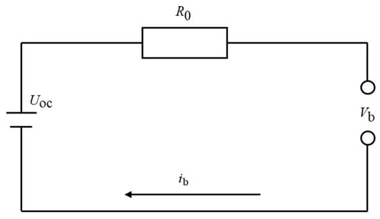
Figure 1.
Equivalent circuit of battery.
The state of charge (SOC) of the power battery is a key parameter for evaluating the remaining usable capacity of the battery. In this paper, the ampere-hour integration method is used to calculate the SOC value of the power battery at the current moment, and the calculation formula is as follows.
2.4. Motor Model
The drive motor is a core component of new energy vehicles and plays a crucial role in the entire electric drive system. It is responsible for converting electrical energy into mechanical energy and propelling the vehicle. The performance of the drive motor directly affects the power, economy, and reliability of new energy vehicles [24].
The expressions for motor torque and required power are as follows:
Since the fully loaded weight of the fuel cell commercial vehicle in this paper is 49 tons, a conventional single motor cannot meet the torque and power requirements. Therefore, a dual power axle with a four-motor configuration is adopted.
3. Design of Vehicle Energy Management Strategy
3.1. Based on Model Predictive Control
In the fuel cell hybrid system, the power battery serves as a buffer device to cope with complex and variable operating conditions [25]. The energy consumed during system operation should be mainly supplied by the fuel cell, while ensuring that the SOC of the power battery is always maintained within a reasonable range [26,27]. Therefore, in this paper, the energy of the lithium-ion battery is converted into an equivalent hydrogen consumption. In the time domain, the equivalent fuel consumption can be expressed as
When the lithium battery is in a charging state, the output power of the lithium battery, Pb(t), is negative. Since the adaptive equivalent factor s is positive, the instantaneous equivalent hydrogen consumption rate of the lithium battery is negative at this time. Consequently, the equivalent hydrogen consumption rate of the entire vehicle power system is less than the actual hydrogen consumption rate of the fuel cell. Conversely, when the lithium battery is discharging, Pb(t) is positive, and the equivalent hydrogen fuel consumption rate of the vehicle power system is greater than the actual hydrogen consumption rate of the fuel cell.
The control system model proposed in this paper is as follows, where X represents the state variables of the system, U represents the control variables, D represents the disturbance variables, R represents the reference variables, and Y represents the output variables. The specific design of the control model is as follows:
The objective function of the control algorithm is as follows:
The constraints of the system are as follows:
In the constraints of the MPC strategy, the state of charge (SOC) of the power battery is constrained within 20–80%, the fuel cell output power is limited to the range of 0 kW to 160 kW, the rate of change in fuel cell power is restricted to 20 kW/s, and the power battery current is limited within ±500 A.
The execution architecture of the control strategy based on model predictive control (MPC) is shown in the figure (Figure 2). The specific operation steps are as follows:
- (a)
- At each control cycle, obtain the current system state and predict the required power for the next N steps.
- (b)
- Solve the optimization problem using MPC to obtain the optimal control sequence for the next N steps.
- (c)
- Apply the first optimal control input and update the system state.
- (d)
- Update the fuel cell performance degradation model.
- (e)
- Move to the next time step and repeat steps a–d.

Figure 2.
Simulation architecture diagram of MPC strategy based on fuel cell degradation.
The controller utilizes the built-in quadratic programming solver in MATLAB R2020a (version 9.8)/Simulink for optimization calculations. To balance real-time performance and optimization effectiveness, the MPC sampling period is set to 1 s, and the prediction horizon is chosen as 10 s, with only one control input executed per rolling optimization. On the simulation platform (AMD R7-4800H CPU, 16 GB RAM, Windows 11), the average computation time per MPC optimization is 28.6 ms, and the maximum computation time does not exceed 42 ms, which is well below the 1 s control interval and fully meets the real-time requirements for engineering applications.
3.2. Based on Fuzzy Logic Control
The membership functions in this study were designed using the Membership Function Editor in MATLAB/Simulink. In the context of a fuel cell hybrid power system, the design of the fuzzy controller’s membership functions should meet the following objectives: Firstly, the state of charge (SOC) of the power battery must be maintained within a reasonable and stable operating range to ensure battery health and longevity. Secondly, the overall energy supply of the vehicle must be sufficient to meet the power demands under various operating conditions. Additionally, to enhance the performance and computational efficiency of the fuzzy controller, the membership functions should satisfy the following requirements: each function must be unimodal, and there should be no overlap between adjacent functions.
For vehicle energy management in fuel cell vehicles, the fuzzy logic controller employing triangular membership functions offers several advantages over other shapes, including higher computational efficiency, flexible parameter adjustment, convenient rule extraction, and strong adaptability. Therefore, triangular membership functions are selected in this study. According to the above principles, the fuzzy subsets corresponding to the three variables are designed as shown in the Figure 3.

Figure 3.
Fuzzy logic control membership function.
The fuzzy logic control strategy was calibrated based on actual vehicle parameters, with the following settings: the maximum power demand of the vehicle is 400 kW, and extreme conditions exceeding 400 kW are not considered for the time being. Considering the vehicle’s regenerative braking capability, the demand power range is set to [−400, 400] kW. The SOC of the power battery is defined within the range [0, 1]. The maximum output power of the fuel cell is 160 kW, so its range is set as [0, 160] kW.
When formulating the fuzzy rules for the fuel cell hybrid power system, the following two principles should be observed: First, during vehicle operation, the fuel cell and the power battery should work cooperatively to jointly meet the energy supply requirements of the whole vehicle. Second, the power battery should operate in a relatively stable state, ensuring that its SOC remains within the specified range. To remain consistent with the previously established requirements for the power battery operating range, the fuzzy control strategy in this paper limits the SOC of the power battery to operate between 20% and 80%. By reasonably formulating fuzzy rules that satisfy the above requirements, efficient energy management and coordinated control of the fuel cell hybrid system can be achieved. The specific fuzzy rules are set as shown in the Table 2.
Table 2.
Fuzzy control rule table.
4. Simulation
In this section, a hybrid electric vehicle model is constructed using AMESim 2304, while the overall vehicle energy management strategy is developed in MATLAB/Simulink. The initial state of the fuel cell applied to a fuel cell tractor is compared in order to investigate the degradation trend of the fuel cell during actual operation. By analyzing vehicle dynamic performance, fuel cell degradation results, and overall vehicle economy, the control effects of different energy management strategies are comparatively evaluated. The vehicle parameters used in the simulation are shown in Table 3.
Table 3.
Vehicle parameter table.
Simulation is carried out under the CHTC-TT China heavy-duty commercial vehicle driving cycle (tractor cycle). The Figure 4 shows the comparison of vehicle dynamics, indicating that both the MPC and FLC energy management strategies can meet the vehicle’s dynamic performance requirements. Whether during vehicle start-up, acceleration, constant-speed cruising, or braking phases, the actual output torque of the drive motor remains highly consistent with the target torque, with the maximum tracking error being less than 3%. Moreover, the vehicle’s acceleration response curve shows no noticeable delay or oscillation, thereby fully meeting the dynamic performance requirements under real-world driving conditions.
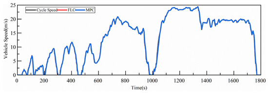
Figure 4.
Vehicle speed comparison under CHTC-TT driving cycle.
4.1. Initial State of the Fuel Cell
Analysis of the fuel cell power variation Figure 5 reveals that the fuzzy logic control (FLC) strategy and the model predictive control (MPC) strategy exhibit different fuel cell power output trends under the CHTC-TT cycle. Throughout the cycle, the FLC strategy results in more pronounced fluctuations in fuel cell power output, accompanied by multiple shutdowns. In contrast, under the MPC strategy, the frequency of fuel cell power fluctuations is reduced, and except for the initial and terminal phases of the cycle, no shutdown events occur.
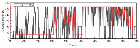
Figure 5.
Power variation diagram of fuel cell under CHTC-TT at initial state.
Specifically, during 0–600 s and 950–1400 s of the driving cycle, the fuel cell output power under the MPC strategy remains highly stable, demonstrating significantly better control of power stability compared to the FLC strategy. However, during 600–950 s and 1400–1800 s, both MPC and FLC strategies experience noticeable fluctuations.
The performance degradation of the fuel cell can mainly be categorized into four aspects: cold start, idling, load variation, and high-power operation. By analyzing the fuel cell power output variations in conjunction with the fuel cell degradation model, the performance degradation results of the fuel cell under the CHTC-TT cycle can be obtained.
According to the end-of-life criteria widely recognized in the fuel cell industry, the service life of a fuel cell is considered to have ended when the nominal voltage or power at the rated operating point decreases by 10%. Analysis of the Table 4 indicates that the vehicle control strategy has a significant impact on fuel cell degradation. After only one CHTC cycle, the fuel cell under the fuzzy logic control strategy experiences a degradation of more than 123 μV, accounting for 0.02% of the fuel cell’s entire life cycle. This implies that under adverse control strategy conditions, the actual operational lifetime of the fuel cell is only about 500 h. In contrast, under the model predictive control (MPC) strategy, after one CHTC cycle, the fuel cell only degrades by 15.67 μV; if start–stop effects are not considered, it would take approximately 15,345 h for the fuel cell to degrade to 10%. When start–stop effects are taken into account, MPC demonstrates a much smaller impact on fuel cell degradation compared to fuzzy logic control, exhibiting a better inhibitory effect on fuel cell degradation. The total degradation of the fuel cell under MPC is reduced by 87% compared to fuzzy logic control.
Table 4.
Degradation voltage of fuel cell under CHTC-TT at initial state.
Among the various factors, start–stop cycles play a significant role in degradation. Under the fuzzy logic control strategy, there are 10 start–stop events during the CHTC-TT cycle, resulting in a degradation of 117.60 μV due to start–stop, which accounts for 92.3% of the total degradation. In comparison, the MPC strategy only incurs one start–stop event during the cycle, leading to a start–stop-related degradation of 11.76 μV—a ninefold reduction compared to fuzzy logic control. Excluding the impact of start–stop events, the degradation caused by other factors under fuzzy logic control is 5.78 μV, while that under MPC is 3.91 μV, representing a 32% reduction compared to fuzzy logic control. Even when excluding start–stop effects, MPC still exerts less impact on fuel cell degradation than fuzzy logic control.
The Figure 6 illustrates the variation in the power battery SOC under the fuzzy logic control strategy and the model predictive control (MPC) strategy. As shown, the SOC of the power battery at the end of the cycle under MPC is 70.7%, with a net change of 0.7% over the entire cycle and a maximum SOC fluctuation of 3.5% during the cycle. Under the fuzzy logic control strategy, the SOC at the end of the cycle is 67.7%, with a net change of −2.7% and a maximum fluctuation of 4.4%.
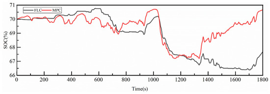
Figure 6.
Comparison of SOC under CHTC-TT at initial state.
Comparative analysis shows that the rolling optimization-based MPC outperforms the fuzzy logic control strategy in terms of maintaining the battery SOC, and it also results in a smaller SOC fluctuation throughout the cycle. The smaller SOC fluctuation further demonstrates the rationality of the vehicle energy management strategy, while reducing unnecessary energy losses and improving overall vehicle economy.
Analysis of the hydrogen consumption table indicates that, in terms of actual hydrogen consumption, the fuzzy logic control strategy saves 352.79 g compared to the model predictive control (MPC) strategy. However, due to differences in the final battery state of charge (SOC) after the execution of each control strategy, it is not appropriate to compare the results using conventional metrics such as cycle fuel consumption or fuel consumption per 100 km, as is common for traditional engines.
Combined with the fuel cell output power diagram, it can be observed that in the fuzzy logic control strategy, the power battery provides more output power, resulting in lower fuel cell output power and consequently lower measured hydrogen consumption. In practical operation, the loss in battery SOC must be compensated by additional hydrogen consumption from the fuel cell to restore the battery to its initial state at the start of the cycle. Therefore, in order to jointly evaluate both battery SOC and hydrogen consumption, the loss in battery SOC should be converted to an equivalent hydrogen consumption. The equivalent hydrogen consumption is then used as a comprehensive metric for comparing the two control strategies.
As shown in the Table 5, when equivalent hydrogen consumption is adopted as the evaluation index, both the battery SOC maintenance level and the equivalent hydrogen consumption of the fuzzy logic control strategy are inferior to those of the MPC strategy presented in this study. Specifically, the equivalent hydrogen consumption increases by 2.15%, and the SOC maintenance lags by 3.4% compared to the MPC strategy.
Table 5.
Equivalent hydrogen consumption table under CHTC-TT at initial state.
4.2. State at the End of Fuel Cell Life
In this section, a comparison is made of the overall vehicle performance when the fuel cell used in a fuel cell tractor experiences a 10% degradation in fuel cell performance. The study investigates the degradation trend of the fuel cell during actual operation. By analyzing the results of fuel cell degradation at the end of its service life and the overall vehicle economy, the control effects of different control strategies are compared and analyzed.
As shown in the Figure 7, the fuzzy logic control strategy and the model predictive control (MPC) strategy exhibit different fuel cell power output trends under the CHTC-TT cycle. Similarly to the initial fuel cell operating state, the fuel cell power output under the fuzzy logic control strategy fluctuates more dramatically throughout the entire cycle and is accompanied by multiple shutdowns. In contrast, under the MPC strategy, the frequency of fuel cell power fluctuations is reduced, and except for the start and end of the cycle, the strategy deliberately avoids the start–stop states of the fuel cell, resulting in no shutdown events.
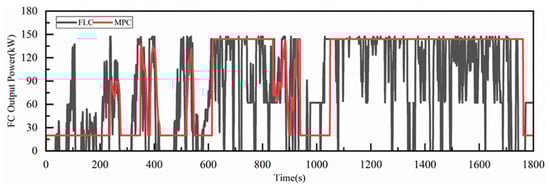
Figure 7.
Power variation diagram of fuel cell under CHTC-TT at end state.
During the intervals of 0–200 s, 600–800 s, and 1000–1800 s within the driving cycle, the fuel cell output power under the MPC strategy remains highly stable, demonstrating a clear advantage over the fuzzy logic control strategy in terms of maintaining power stability during operating condition changes. However, in the periods of 200–600 s and 800–1000 s, both the MPC and fuzzy logic control strategies exhibit noticeable fluctuations.
After a 10% degradation in fuel cell performance, the variation in fuel cell power output, combined with the fuel cell degradation model, allows for the determination of the fuel cell degradation results under the CHTC-TT cycle. The results are shown in the Table 6.
Table 6.
Degradation voltage of fuel cell under CHTC-TT at end state.
A comparison between the initial and end states of fuel cell degradation reveals that the operating characteristics of the degraded fuel cell differ significantly from those of a brand-new fuel cell. Under the fuzzy logic control strategy, after one CHTC-TT cycle, the total fuel cell degradation voltage is approximately 54.76 μV, which is markedly different from the 123.38 μV observed for a new fuel cell under the same control strategy. This improvement is attributed to the reduction in the number of start–stop events, which decreased from 9 to 4, resulting in a decrease in the degradation voltage attributable to start–stop events from 117.60 μV to 47.04 μV. This is because the rated power of the degraded fuel cell is lower, and to meet the vehicle’s power demand, the average operating power of the fuel cell increases.
Under the model predictive control (MPC) strategy, after completing one CHTC cycle, the fuel cell degradation voltage is only 16.23 μV, which is a 3.6% increase compared to the 15.67 μV degradation of a new fuel cell. This is mainly due to the substantial reduction in maximum power caused by severe fuel cell degradation, resulting in more degradation occurring in the high-power operating region.
At the end of the fuel cell’s service life, the MPC strategy has a significantly smaller impact on fuel cell degradation compared to the fuzzy logic control strategy, demonstrating a superior ability to mitigate fuel cell degradation. The total fuel cell degradation under MPC is approximately 70% lower than that under fuzzy logic control. The impact of start–stop events is particularly significant; under fuzzy logic control in the CHTC-TT cycle, four start–stop events result in a degradation voltage of 47.04 μV, accounting for 85.9% of the total degradation. In contrast, the MPC strategy involves only one start–stop event during the cycle, resulting in a degradation voltage of 11.76 μV, a 75% reduction compared to fuzzy logic control.
Excluding the manually controllable influence of start–stop events, the fuel cell voltage degradation caused by other factors is 7.72 μV under fuzzy logic control and 4.47 μV under MPC, representing a reduction of approximately 42% with MPC. Even when the influence of start–stop events is excluded, the MPC strategy still results in less fuel cell degradation than the fuzzy logic control strategy.
In terms of actual hydrogen consumption, the fuzzy logic control strategy results in a reduction of 752.49 g compared to the model predictive control (MPC) strategy. However, since the final state of charge (SOC) of the power battery differs between the two control strategies, it is more reasonable to use the vehicle’s equivalent hydrogen consumption for comparison. According to the fuel cell output power profiles, the fuzzy logic control strategy involves a greater output from the power battery, leading to lower fuel cell output power and, thus, lower measured hydrogen consumption for the entire vehicle. In practical operation, the power deficit in the battery must be replenished by the fuel cell through additional hydrogen consumption to restore the battery to its initial SOC at the start of the cycle. The comparative results are shown in the following table.
As shown in the Table 7 and Figure 8, using equivalent hydrogen consumption as an evaluation metric allows for a comprehensive assessment that considers both the maintenance of power battery SOC and the measured hydrogen consumption. Compared to the model predictive control (MPC) strategy employed in this study, the fuzzy logic control strategy achieves a 1.48% reduction in equivalent hydrogen consumption, but lags behind by 4.2% in SOC maintenance. This demonstrates that, after degradation, the fuzzy logic control strategy offers an advantage in hydrogen consumption under the CHTC-TT cycle compared to MPC, but exhibits inferior SOC maintenance performance.
Table 7.
Equivalent hydrogen consumption table under CHTC-TT.
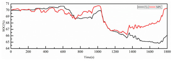
Figure 8.
Comparison of SOC changes under CHTC-TT at end state.
5. Conclusions
This study addresses the critical challenge of optimizing energy economy and component durability for hybrid electric commercial vehicles (HECVs) operating under complex driving cycles. To achieve synergistic optimization of these often conflicting objectives, a novel model predictive control (MPC)-based energy management strategy, incorporating real-time component health awareness, is proposed and validated.
The core contribution lies in the deep integration of dynamic component degradation models into the MPC framework. This integration establishes a feedback mechanism where the current and predicted health status of key components becomes a fundamental input for online control decisions. Within its rolling horizon paradigm, the MPC strategy proactively orchestrates the power split between the engine/battery and electric motor(s). This optimization explicitly coordinates the minimization of equivalent energy consumption with the active mitigation of component degradation.
Comprehensive simulations demonstrate the significant advantages of the proposed strategy over traditional approaches:
Durability Enhancement: Component degradation is drastically reduced by up to 87%, primarily attributed to the strategy’s ability to avoid high-stress operating conditions (e.g., excessive load transients, deep cycling) predicted to accelerate wear.
Economy Improvement: Equivalent energy efficiency is improved by approximately 3.5%, showcasing the strategy’s capability to utilize energy more effectively across the driving cycle while managing component health.
System Stability: Superior state of charge (SOC) maintenance is achieved, indicating enhanced robustness and stability of the energy storage system under the control strategy. Vehicle drivability requirements are consistently met.
In summary, this work successfully demonstrates that real-time awareness and predictive management of component health status are essential for unlocking the full potential of HECVs. The developed MPC-based co-optimization strategy provides an effective and intelligent control solution, paving the way for longer-lasting, more economical, and higher-performing hybrid commercial fleets. The methodology offers a valuable framework applicable to diverse hybrid powertrain architectures seeking performance–life co-optimization.
Author Contributions
Conceptualization, S.B.; methodology, Y.W.; software, W.S.; project administration, K.S.; formal analysis, Y.W.; writing—original draft preparation, Y.W. and S.Q.; investigation, W.S. and S.Q.; data curation, Y.W. and S.Q.; writing—review and editing, S.B. and K.S.; funding acquisition, S.B. All authors have read and agreed to the published version of the manuscript.
Funding
This research was funded by Shandong Provincial Technology Innovation Guidance Program Project, grant number YDZX2023114; Shandong Province Engineering Machinery Intelligent Equipment Innovation and Entrepreneurship Community Project, grant number GTT20240101.
Data Availability Statement
The data presented in this study are available upon request from the corresponding author.
Conflicts of Interest
Author Shunshun Qin was employed by the company Weichai Power Co., Ltd. The remaining authors declare that the research was conducted in the absence of any commercial or financial relationships, and there are no potential conflicts of interest.
Nomenclature
| Symbol | Description |
| m | Mass |
| CD | Drag coefficient |
| A | Frontal area |
| Cell voltage | |
| Ideal electromotive force | |
| Activation overpotential | |
| Ohmic overpotential | |
| Concentration overpotential | |
| Gibbs free energy change value | |
| Faraday constant | |
| Entropy change | |
| Temperature of fuel cell | |
| Reference temperature | |
| Gas constant. | |
| Hydrogen partial pressure | |
| Oxygen partial pressure | |
| Exchange current constant | |
| Stack current density | |
| Internal current density | |
| Exchange current density | |
| Membrane resistance | |
| Concentration voltage drop coefficient | |
| Limited Current Density | |
| Actual working voltage | |
| The initial voltage of the fuel cell | |
| Degradation rate | |
| Degradation rate in low power | |
| Degradation rate in normal power | |
| Degradation rate in load change | |
| Degradation rate at start/stop | |
| Count of start/stop | |
| Coefficient of low power | |
| Coefficient of normal power | |
| Coefficient of load change | |
| Polarization voltage coefficient | |
| Ohmic resistance | |
| Electronic impedance | |
| Ion impedance | |
| Contact impedance | |
| Ohmic voltage coefficient | |
| Ohmic and Concentration polarization coefficient | |
| Electrochemical coefficient of load transformation | |
| Fuel cell power | |
| SOC variation | |
| Battery capacity | |
| Battery charge efficiency | |
| Low heating value of hydrogen gas |
References
- Enang, W.; Bannister, C. Modelling and Control of Hybrid Electric Vehicles (A Comprehensive Review). Renew. Sustain. Energy Rev. 2017, 74, 1210–1239. [Google Scholar] [CrossRef]
- Bai, S.; Liu, C. Overview of Energy Harvesting and Emission Reduction Technologies in Hybrid Electric Vehicles. Renew. Sustain. Energy Rev. 2021, 147, 111188. [Google Scholar] [CrossRef]
- Shen, Y.; Li, Y.; Liu, D.; Wang, Y.; Sun, J.; Sun, S. Energy Management Strategy for Hybrid Energy Storage System Based on Model Predictive Control. J. Electr. Eng. Technol. 2023, 18, 3265–3275. [Google Scholar] [CrossRef]
- Aminudin, M.A.; Kamarudin, S.K.; Lim, B.H.; Majilan, E.H.; Masdar, M.S.; Shaari, N. An Overview: Current Progress on Hydrogen Fuel Cell Vehicles. Int. J. Hydrogen Energy 2023, 48, 4371–4388. [Google Scholar] [CrossRef]
- Teng, T.; Zhang, X.; Dong, H.; Xue, Q. A Comprehensive Review of Energy Management Optimization Strategies for Fuel Cell Passenger Vehicle. Int. J. Hydrogen Energy 2020, 45, 20293–20303. [Google Scholar] [CrossRef]
- Kandidayeni, M.; Trovão, J.P.; Soleymani, M.; Boulon, L. Towards Health-Aware Energy Management Strategies in Fuel Cell Hybrid Electric Vehicles: A Review. Int. J. Hydrogen Energy 2022, 47, 10021–10043. [Google Scholar] [CrossRef]
- Kandidayeni, M.; Macias, A.; Boulon, L.; Kelouwani, S. Investigating the Impact of Ageing and Thermal Management of a Fuel Cell System on Energy Management Strategies. Appl. Energy 2020, 274, 115293. [Google Scholar] [CrossRef]
- Lü, X.; Wu, Y.; Lian, J.; Zhang, Y.; Chen, C.; Wang, P.; Meng, L. Energy Management of Hybrid Electric Vehicles: A Review of Energy Optimization of Fuel Cell Hybrid Power System Based on Genetic Algorithm. Energy Convers. Manag. 2020, 205, 112474. [Google Scholar] [CrossRef]
- Wu, X.-H.; Yu, Z.-W.; Zhu, Z.-L.; Gao, X.-M. Fuzzy energy management strategy of fuel cell buses. J. Jilin Univ. (Eng. Technol. Ed.) 2022, 52, 2077–2084. [Google Scholar] [CrossRef]
- Ganesh, A.H.; Xu, B. A Review of Reinforcement Learning Based Energy Management Systems for Electrified Powertrains: Progress, Challenge, and Potential Solution. Renew. Sustain. Energy Rev. 2022, 154, 111833. [Google Scholar] [CrossRef]
- Wang, Y.; Advani, S.G.; Prasad, A.K. A Comparison of Rule-Based and Model Predictive Controller-Based Power Management Strategies for Fuel Cell/Battery Hybrid Vehicles Considering Degradation. Int. J. Hydrogen Energy 2020, 45, 33948–33956. [Google Scholar] [CrossRef]
- Kandidayeni, M.; Macias, A.; Boulon, L.; Kelouwani, S. Efficiency Upgrade of Hybrid Fuel Cell Vehicles’ Energy Management Strategies by Online Systemic Management of Fuel Cell. IEEE Trans. Ind. Electron. 2021, 68, 4941–4953. [Google Scholar] [CrossRef]
- Hybrid and Electric Vehicles—A Comprehensive Guide. Available online: https://www.researchgate.net/publication/379907499_Hybrid_and_Electric_Vehicles_-_A_Comprehensive_Guide (accessed on 11 August 2025).
- Lü, X.; Li, S.; He, X.; Xie, C.; He, S.; Xu, Y.; Fang, J.; Zhang, M.; Yang, X. Hybrid Electric Vehicles: A Review of Energy Management Strategies Based on Model Predictive Control. J. Energy Storage 2022, 56, 106112. [Google Scholar] [CrossRef]
- Zhou, J.; Liu, J.; Xue, Y.; Liao, Y. Total Travel Costs Minimization Strategy of a Dual-Stack Fuel Cell Logistics Truck Enhanced with Artificial Potential Field and Deep Reinforcement Learning. Energy 2022, 239, 121866. [Google Scholar] [CrossRef]
- Pereira, D.F.; Lopes, F.d.C.; Watanabe, E.H. Nonlinear Model Predictive Control for the Energy Management of Fuel Cell Hybrid Electric Vehicles in Real Time. IEEE Trans. Ind. Electron. 2021, 68, 3213–3223. [Google Scholar] [CrossRef]
- Tang, X.; Zhou, H.; Wang, F.; Wang, W.; Lin, X. Longevity-Conscious Energy Management Strategy of Fuel Cell Hybrid Electric Vehicle Based on Deep Reinforcement Learning. Energy 2022, 238, 121593. [Google Scholar] [CrossRef]
- Fletcher, T.; Thring, R.; Watkinson, M. An Energy Management Strategy to Concurrently Optimise Fuel Consumption & PEM Fuel Cell Lifetime in a Hybrid Vehicle. Int. J. Hydrogen Energy 2016, 41, 21503–21515. [Google Scholar] [CrossRef]
- Pei, P.; Chang, Q.; Tang, T. A Quick Evaluating Method for Automotive Fuel Cell Lifetime. Int. J. Hydrogen Energy 2008, 33, 3829–3836. [Google Scholar] [CrossRef]
- Sun, W.; Li, M.; Su, G.; Li, G.; Cheng, H.; Sun, K.; Bai, S. Effects of Fuel Cell Size and Dynamic Limitations on the Durability and Efficiency of Fuel Cell Hybrid Electric Vehicles under Driving Conditions. Appl. Sci. 2024, 14, 2459. [Google Scholar] [CrossRef]
- Pei, P.; Meng, Y.; Chen, D.; Ren, P.; Wang, M.; Wang, X. Lifetime Prediction Method of Proton Exchange Membrane Fuel Cells Based on Current Degradation Law. Energy 2023, 265, 126341. [Google Scholar] [CrossRef]
- Zhao, N.; Chu, Y.; Xie, Z.; Eggen, K.; Girard, F.; Shi, Z. Effects of Fuel Cell Operating Conditions on Proton Exchange Membrane Durability at Open-Circuit Voltage. Fuel Cells 2020, 20, 176–184. [Google Scholar] [CrossRef]
- Jia, C.; Zhou, J.; He, H.; Li, J.; Wei, Z.; Li, K.; Shi, M. A Novel Energy Management Strategy for Hybrid Electric Bus with Fuel Cell Health and Battery Thermal- and Health-Constrained Awareness. Energy 2023, 271, 127105. [Google Scholar] [CrossRef]
- Hu, H.; Yuan, W.-W.; Su, M.; Ou, K. Optimizing Fuel Economy and Durability of Hybrid Fuel Cell Electric Vehicles Using Deep Reinforcement Learning-Based Energy Management Systems. Energy Convers. Manag. 2023, 291, 117288. [Google Scholar] [CrossRef]
- Di Trolio, P.; Di Giorgio, P.; Genovese, M.; Frasci, E.; Minutillo, M. A Hybrid Power-Unit Based on a Passive Fuel Cell/Battery System for Lightweight Vehicles. Appl. Energy 2020, 279, 115734. [Google Scholar] [CrossRef]
- Ghorashi Khalil Abadi, S.A.; Habibi, S.I.; Khalili, T.; Bidram, A. A Model Predictive Control Strategy for Performance Improvement of Hybrid Energy Storage Systems in DC Microgrids. IEEE Access 2022, 10, 25400–25421. [Google Scholar] [CrossRef]
- Hu, H.; Ou, K.; Yuan, W.-W. Fused Multi-Model Predictive Control with Adaptive Compensation for Proton Exchange Membrane Fuel Cell Air Supply System. Energy 2023, 284, 128459. [Google Scholar] [CrossRef]
Disclaimer/Publisher’s Note: The statements, opinions and data contained in all publications are solely those of the individual author(s) and contributor(s) and not of MDPI and/or the editor(s). MDPI and/or the editor(s) disclaim responsibility for any injury to people or property resulting from any ideas, methods, instructions or products referred to in the content. |
© 2025 by the authors. Licensee MDPI, Basel, Switzerland. This article is an open access article distributed under the terms and conditions of the Creative Commons Attribution (CC BY) license (https://creativecommons.org/licenses/by/4.0/).