Abstract
Clamp repair is a primary method for defective pipe rehabilitation, but the application of repair clamps can conversely affect the safety of the defective pipe. This study presents an optimized repair clamp structure for a defective pipe with diameter of 219 mm through finite element analysis and experimental validation, with a consideration of the sealing performance of clamp. The sealing capability is first verified by contact pressure analysis. When the medium pressure increased from 5 MPa to 20 MPa, the sealing contact pressure correspondingly rose from 11.6 MPa to 27.2 MPa, consistently exceeding the medium pressure. A sensitivity analysis of the maximum safe pressure of defective pipe is then conducted, evaluating critical parameters including defect dimensions, clamp installation distance, and applied pressure range. To ensure safe pipe operation, the recommended optimal installation distance is approximately 40 mm. A hydrostatic pressure test is performed for final validation. Results confirmed the clamp’s robust sealing performance, enabling defective pipe to operate normally at 7.5 MPa medium pressure.
1. Introduction
The operation of oil and gas pipes occurs in extremely complex environments [1], where external factors inevitably induce various defects during the service [2]. These defects significantly compromise pipe integrity by reducing both the maximum safe operating pressure and structural reliability [3,4]. To solve these challenges, clamp repair technologies have emerged as a critical solution for both emergency interventions and permanent repairs, owing to their exceptional pressure-containing capability and modular design.
To avoid the leakage of pipe by using clamp technology, the clamp design must be implemented to ensure a reliable sealing capability at the repair location. Sealing performance represents the most critical technical aspect of repair clamps. In recent years, several studies have been devoted to finding the best design of repair clamps for defective pipes [5,6,7], and their sealing performances were also studied [8,9]. Sum et al. [10] developed a resin-infused and fiber-reinforced repair clamp that achieves superior lightweight properties and corrosion resistance without compromising the structural integrity of the defective pipe. Parallel innovations by Cao et al. [11] in graphite sealing materials and Zhao et al.’s [12,13] graded-hardness rubber designs have both significantly enhanced the sealing performance of repair clamps. Alnaser et al. [14] further advanced this field by developing an innovative composite pipe repair design utilizing a bi-material interface optimized through swarm intelligence techniques, achieving enhanced fracture resistance with minimal repair thickness while maximizing pressure-bearing capacity, thus offering a lightweight, high-strength alternative to traditional steel sleeves for corrosion-damaged pipelines. Expanding beyond metallic pipelines, Zhang et al. [15] experimentally demonstrated that ultra-high-performance concrete (UHP-ECC) mortar spraying can restore the bearing capacity of corrosion-thinned reinforced concrete pipes, with performance governed by corrosion degree, repair thickness, and interface morphology.
Finite element analysis combined with orthogonal experimental design has revealed that three critical parameters, such as rubber-to-pipe clearance, sealing ring positioning, and friction coefficient, predominantly determine the sealing efficacy of double-sealing clamp systems [16]. Recent breakthroughs in sealing technology, such as the magnetorheological adhesive-based emergency sealing proposed by Ma et al. [17], have demonstrated exceptional performance under high-pressure conditions through full-scale experiments, while Zhao et al. [18] systematically optimized wedge contact seals in subsea clamps using 3D simulation, providing new insights into pressure distribution control. Complementing these advances, Zhang et al. [19] established, through full-scale testing and FEM, that mortar-sprayed rehabilitation maintains structural performance in corroded concrete pipes under traffic loads, providing a theoretical foundation for non-destructive repair methods. However, these research advances primarily focus on the analysis of repair clamp, while neglecting to consider the structural integrity of a pipe under the influence of the installed repair clamps.
Several researchers have conducted systematic investigations into the safe pressure of defective pipes. Fekete et al. [20] employed finite element analysis to examine the effect of width-to-length ratios of corrosion defects on the burst pressure of steel pipes, with validation by experimental measurements. Their later work further addressed gaps in semi-empirical codes by correlating defect geometry with failure risks through FEA-validated models. He et al. [21] investigated the buckling behavior of thick-walled pipes under external pressure and developed a simplified equation for predicting critical plastic collapse pressure that demonstrated strong agreement with experimental data. Mazurkiewicz et al. [22] found that the pipes with localized wall-thinning corrosion defects can be reinforced by fiber-reinforced polymer (FRP) composite sleeves, which could achieve improved burst pressure performance. Djukic et al. [7] confirmed this advantage by testing novel FRP composite clamps, showing a 40% weight reduction and superior leak containment compared to metallic solutions. Liu et al. [23] systematically characterized the effect of length-to-diameter ratios on the collapse behavior of clamp-repaired pipes. Complementing this, Zhang et al. [24] employed the Analytic Hierarchy Process (AHP) to prioritize failure modes of pipe-in-pipe systems under multifactorial loads, while Vijaya Kumar et al. [25] achieved breakthrough accuracy (R2 = 0.99) in predicting failure pressures of corroded pipes through ANN modeling. However, the effects of the loading condition and defect behavior on the maximum value of safe pressure are still critical problems for the application of repair clamp.
In this work, the sealing performance of repair clamps and their influence on pipe safe pressure were both investigated. The structural optimization of a repairing clamp for a defective pipe with a 219 mm diameter is investigated through finite element analysis (FEA) and experimental validation. The sealing performance of the clamp is evaluated under a series of internal pressures, followed by a sensitivity analysis of the defective maximum safe pressure of defective pipe, considering critical parameters such as defect geometry and clamp installation conditions. A hydrostatic pressure testing platform was established to further validate the sealing performance and installation feasibility of the optimized repair clamp. This research can provide valuable guidance for the subsequent structural design and standardized installation of repair clamps.
2. Materials and Methods
2.1. Structural Design of Repair Clamp
Based on the leakage repair requirements for a pipe with a typical outer diameter of 219 mm, a repair clamp structure of defective pipe is designed by modifying the original structure, as illustrated in Figure 1. The device consists of a load-bearing structure made of AISI 1020 and a sealing structure composed of nitrile rubber (NBR), forming a lightweight repair solution. The dimensional parameters of the main structure are listed in Table 1, and the corresponding mechanical properties of AISI 1020 and NBR are listed in Table 2, which were measured by another research team [26].
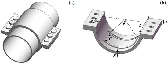
Figure 1.
(a) Schematic diagram of pipe repair clamp; (b) dimensional parameters of structure.

Table 1.
Repair fixture dimension parameters.
Table 2.
Mechanical properties of materials [26].
2.2. Finite Element Model
The finite element software Abaqus 2020 is utilized for modeling and computational analysis. The sealing material of the repair clamp was made of nitrile rubber (NBR) [27]. The NBR exhibits hyperelastic characteristics and can be treated as an incompressible material in finite element simulations, demonstrating highly nonlinear behavior. The Mooney–Rivlin model (Equation (1)) was employed [28], as it effectively describes the mechanical behavior of rubber materials while maintaining high fitting accuracy and computational precision. The model parameters were set to values of C10 = 0.96 and C01 = 0.28, with a hardness of IRHD 75 [29,30]. Considering the material properties and structural symmetry, the rubber numerical model is discretized using first-order quadrilateral axisymmetric hybrid elements (CAX4H), as illustrated in Figure 2. During the preliminary experimental phase, systematic mesh sensitivity analyses were conducted and ultimately determined the optimal mesh size through iterative calculations, as illustrated in Appendix A, Figure A1. The final model employed 4481 uniformly sized elements with a characteristic length of 0.15 mm, thereby ensuring the accuracy of numerical simulation results. A contact friction coefficient of 0.2 was defined between the rubber and both the outer clamp body and the inner pipeline surface. The outer contact surface was subjected to fully fixed symmetric constraints, while the inner contact surface was axially con-strained. A load was applied as a surface pressure, simulating a compression axial load. Different surface pressure loads are applied in the simulation to analyze the sealing performance under varying medium pressures Pm. According to the principles of sealing design, the sealing pressure of a clamp is determined by the contact pressures on the sealing surfaces between the seals and the surrounding structure [18]. To achieve reliable sealing, the effective contact pressure should be greater than the medium pressure over a certain contact length; otherwise, leakage will occur. Therefore, the effective contact pressure is chosen as the evaluation criterion for the clamp’s sealing performance. At the same time, leakage usually occurs in areas with the lowest tightness, where the contact pressure is minimal and may be insufficient to ensure sealing.
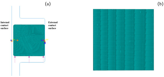
Figure 2.
Finite element model of device: (a) overall structure; (b) rectangular sealing ring.
To conduct research and analysis on the influencing factors of pipe safe pressure, a pipe model is established. The thickness of pipe is selected in accordance with GB/T 17395-2024 [31]. To account for the effects of edge, the pipe length was set to twice than the outer diameter of pipe’s model. The complex defect geometry was simplified into a rectangular shape for analysis. AISI 1020 steel was modeled assuming linear elastic behavior for simplified calculation. Moreover, the linear elastic solution overestimates stresses, which enables a conservative safety assessment when combined with plastic failure criteria. By the same token, the systematic mesh sensitivity analyses were conducted, and the final model employed 9914 uniformly sized elements with a characteristic length of 10 mm, thereby ensuring the accuracy of numerical simulation results. Given that the axial strain was significantly smaller than the circumferential strain in the pipe, the model was simplified by assuming no axial displacement. Thus, both ends of the pipe model were assigned fully fixed constraints. Additionally, the mechanical interaction between the repair clamp and the pipe was modeled as a radially inward uniform pressure applied to the pipe’s outer surface via the clamp’s internal sealing component. Figure 3a presents a quarter-section model of the defective pipe, where φ is the defect angle, d2 is the defect depth, and d1 is the pipe wall thickness. Figure 3b presents the meshed model, with local grid refinement near the defect zone for multiple L2 loading positions. Measurement points were selected at three locations through the wall thickness: the outer surface, mid-wall, and inner surface of the defect area. Figure 3c illustrates the load application of the repair clamp, where L1 represents the distance between the clamp load and the defect and L2 denotes the load application width. The plastic failure criterion is selected as the failure assessment criterion for defective pipelines under mechanical loading in this study. If the minimum value among these nodes exceeds the material yield strength, the corresponding medium pressure can be regarded as the safe pressure of the defective pipe.
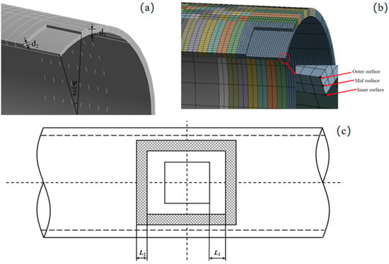
Figure 3.
(a) Defective pipe model. (b) Finite element model. (c) Schematic diagram of clamp mounting position.
2.3. Experimental Design
The experiment platform is established as shown in Figure 4, with the testing methodology referencing relevant standards from the American Society of Mechanical Engineers (ASME) [32]. Temperature significantly affects the properties of rubber seals and the differential thermal expansion between steel and rubber components [33,34]. However, in this experiment, conducted at ambient temperature, the pressure was applied incrementally in three controlled stages. No measurable temperature fluctuation was detected during pressurization. Therefore, thermal effects on the rubber model were justifiably excluded from consideration three stages during the pressurization process. Since no heat generation was observed, the influence of temperature on the rubber model was not considered in this study. The manually operated hydraulic pump ST-10 with a rated pressure of 10 MPa and water as the working medium is employed for medium pressure application. Medium pressure is measured by using a precision pressure gauge with full-scale range of 16 MPa and the accuracy of 0.5%. Strain measurements are acquired through a static strain acquisition system (DH3818N-2) operating at 10 Hz sampling frequency, and its measurement accuracy is 0.5%. Due to the measurement limitations of contact strain gauges, directly measuring the contact pressure at the center of the clamp poses technical challenges and may introduce leakage risks. Therefore, this study places the strain gauges on the outer side of the repair clamp, concentrating within the range of the defect center. By comparing the simulated and experimental values of the outer deformation, the consistency between the model’s central contact pressure and the experimental deformation is indirectly validated [35]. Nine strain gauges were measured at critical locations on the device. The specific locations of all strain gauges are illustrated in Figure 5. The six strain gauges, named H1 to H6, are arranged in circumferential orientation, while other strain gauges, named AX1 to AX3, are installed axially of the device. This configuration enabled independent measurement of both axial and circumferential strain variations during the loading process.
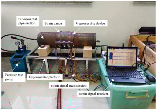
Figure 4.
Experimental platform for defective pipe and the repair clamp device.
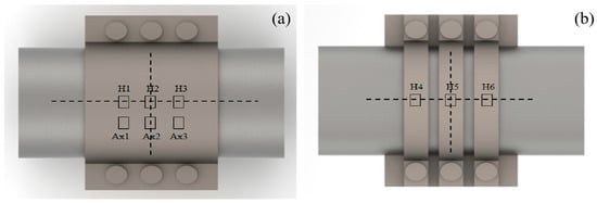
Figure 5.
Locations of nine strain gauges: (a) H1 to H3 and AX1 to AX3; (b) H4 to H6.
Following the installation of the repair clamp, water is injected to purge air from the sealing cavity before connecting the hydraulic hand pump for formal testing. The working pressure of the test defective pipe is 5 MPa. According to standard practice, the hydrostatic test pressure is typically selected as 1.5 times, which is 7.5 MPa. It is applied through three stages; the medium pressure is applied from atmospheric pressure to 2.5 MPa at first stage, then the medium pressure increases to 5 MPa, and finally the medium pressure is applied to 7.5 MPa. After each loading step, the inspections of cracking and sealing performance are conducted, and all test results systematically recorded.
3. Results and Discussions
3.1. Sealing Performance of Repair Clamps
According to GB/T 20801, the maximum design pressure for pipe of 20 steel with a 219 mm diameter can reach 23 MPa [36], while the conservative design pressure is recommended at 20 MPa. The sealing assembly is subjected to medium pressures Pm of 5 MPa, 10 MPa, 15 MPa, and 20 MPa under compressive loading conditions, with comparative analysis performed against the non-pressurized state. As illustrated in Figure 6, the high-stress zone is primarily concentrated at the four corners of the rectangular seal model under the Pm of 0 MPa, while a low-stress zone presents in the middle of both left and right edge. This phenomenon could result from the geometric characteristics of the rectangular seal. During compression, the four endpoints of the seal cannot slide toward the edges of the sealing surface due to frictional constraints, leading to a stress concentration at the corner. When the Pm increases to 10 MPa, the rectangular rubber ring is extruded into the sealing gap between the groove and inner shaft, causing the high-stress region to the extruded area. With the increasing value of Pm from 0 to 20 MPa, the corresponding peak stress values also increased from 4.23 to 12.55 MPa. Furthermore, as the medium pressure continues to increase, the red-colored regions (indicating higher stress) in the stress contour gradually diminish, demonstrating that stress concentration becomes more pronounced with elevated pressure. Although severe stress concentration occurs in the extrusion zone of the sealing gap, the maximum von Mises stress of the seal (approximately 12.55 MPa) under 20 MPa pressure remains within the safe range compared to the tensile strength (27.0 MPa) of NBR.
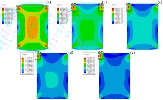
Figure 6.
Von Mises stress contour of seals under different medium pressures Pm: (a) 0 MPa; (b) 5 MPa; (c) 10 MPa; (d) 15 MPa; (e) 20 MPa.
To achieve effective sealing, it is essential to ensure that the contact pressure of seals exceeds the medium pressure Pm while maintaining a certain contact length. The average contact pressure along this contact length is defined as the effective contact pressure. Figure 7 illustrates the influence of varying medium pressures on the maximum, average, and minimum contact stresses of the sealing element. The results demonstrate that as the medium pressure increases from 5 to 20 MPa, the effective pressure rises correspondingly from 8.1 MPa to 22.9 MPa. Throughout this process, the effective contact pressure consistently remains higher than the medium pressure. Furthermore, the minimum contact pressure always exceeds the medium pressure, effectively eliminating the possibility of leakage. This behavior indicates effective pressure-adaptive sealing capability, where the seal maintains positive pressure differentials even under different medium pressures.
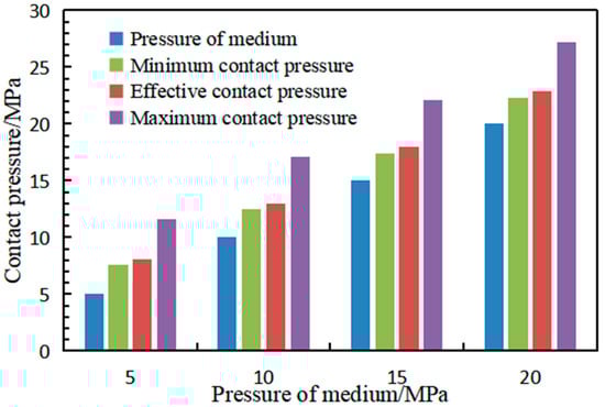
Figure 7.
Maximum value of contact stress of seals under different medium pressures.
3.2. Analysis of Factors Affecting Pipe Safe Pressure
3.2.1. Effect of Defect on the Safe Pressure
Finite element analysis is conducted with corrosion widths of 10–50° (in 10° increments) and depth ratios d1/d2 ranging from 0.2 to 0.8. Figure 8 illustrates the relation between these defect parameters and the maximum safe pressure of pipe. It also shows a pronounced dependence of maximum safe pressure of pipe on the pipe’s defect depth. Quantitative analysis demonstrates that an increase of 0.2 in defect depth correlates with a reduction of 18.7 ± 2.3% in pressure containment capacity, revealing that the defect depth is the dominant geometric parameter to effect on the pipe’s structural integrity. The pipe exhibits its minimum maximum safe pressure when the defect depth ratio d1/d2 reaches 0.8. In contrast, FEA results show that the effects of defect’s width variation (range of 10–50 mm) on pressure capacity is insignificant. These findings demonstrate that pipe pressure safety assessments may neglect width effects but must account for defect depth impacts.
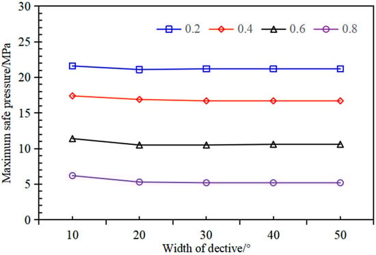
Figure 8.
Relation between safe pressure of defective pipe and defect.
This study investigated the influence of pipe thickness on maximum safe pressure under controlled defect conditions. The numerical analysis maintained a constant defect depth ratio of 0.5, where the defect depth is half of the pipe wall thickness, combined with a 20° defect width. The pipe thickness is systematically increased from 6 to 12 mm to analyze its influence on pressure containment capacity. To characterize the mechanical response to clamp-induced loading, an external contact stress of 20 MPa is applied, corresponding to the maximum interface pressure documented in prior experimental studies. Figure 9 shows that the maximum safe pressure of detective pipe is positively correlated with the thickness of the pipe and external pressure loading. Specifically, as the thickness of detective pipe is incrementally raised from 6 mm to 12 mm, the maximum safe pressure demonstrates a significant increase from 7.6 MPa to 16.1 MPa and the application of external clamping load reduces the maximum safe pressure of detective pipe, exhibiting a 2.4 MPa decrease for a thickness of 6 mm. However, this weakening effect diminishes with increasing thickness. It is evident that external loading exerts negligible influence on the pipe’s safe pressure at a thickness of 12 mm. Consequently, under identical defect dimensions, external clamping pressure represents a critical design consideration for a defective pipe with 6 mm wall thickness, requiring particular attention during safe pressure assessments.
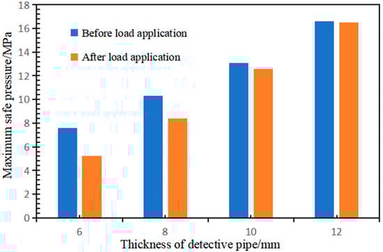
Figure 9.
Relation between change in maximum safe pressure and thickness of pipe.
In summary, the most critical operating condition occurs when the thickness of the pipe is 6 mm, with a maximum defect depth ratio d2/d1 of 0.8. The defect width shows a negligible influence on the maximum safe pressure and is set at 20° as a conservative value. According to the ASME B31G [37] criterion, for corrosion defects with given depths which exceed 0.2 but remain below 0.8, the maximum allowable length of the defect when approximated by a parabolic profile is determined by Equations (2) and (3). Therefore, the most critical operating conditions for the pipe of 219 mm, including the thickness of pipe and defect dimensions, are summarized in Table 3. It should be noted that the core logic of this study is to evaluate the pipe stress state based on defect parameters, pipe geometric characteristics, and clamp pressure, with the von Mises stress serving as the key criterion for determining whether the medium pressure meets safety requirements. Furthermore, since the maximum allowable defect length specified in ASME B31G is generally conservative with actual critical lengths potentially being greater, Formulas (2) and (3) can be directly applied for assessment. The calculated maximum allowable length is treated as a defect parameter to identify the most critical operating conditions. On this basis, the influence of the repair clamp on the safe pressure is further investigated.
Table 3.
Critical parameters of defective pipe.
3.2.2. Effects of Repair Clamp Device on Safe Pressure
Under the most critical defect conditions, the effects of the repair clamp parameters of load magnitude P, application width L2, and distance from the defect L1 are investigated. With medium pressure alone, the pipe’s maximum safe pressure is 6.5 MPa. Experimental results demonstrate that clamp-applied external pressures between 10 and 20 MPa significantly affect the maximum safe pressure of corroded pipe as Table 4. The ‘–’ symbol denotes cases where the maximum safe pressure fails to reach the 6.5 MPa threshold, indicating that the repair clamp reduces the maximum safe pressure of defective pipe under these operating conditions.
Table 4.
Maximum safe pressure of defective pipe.
Figure 10 shows a characteristic non-monotonic relationship between the maximum safe pressure of defective pipe and the external-load application distance. These results demonstrate that increasing the external load application width L2 from 10 to 30 mm significantly amplifies its influence on the safe pressure capacity of defective pipes under identical loading conditions. This effect proves particularly pronounced when the installation distance is below the 40 mm threshold, where wider load application correlates with greater pressure capacity reduction. Under operational conditions with an external-load width L2 of 30 mm, installation distance L1 of 10 mm, and load pressure P ranging from 14 to 20 MPa, the maximum safe pressure consistently remains below 6.5 MPa for all tested cases. Moreover, the experimental results also identify the installation distance L1 as the critical factor governing the maximum safe pressure of defective pipe. For the tested pipe geometry and defect dimensions, 40 mm emerges as the threshold distance determining the clamp’s mechanical influence. When the installation distance of the repair device is less than 40 mm, the safe pressure of the defective pipe may be compromised due to the intervention. When the installation distance of the repair clamp exceeds 40 mm, the maximum safe pressure stabilizes at approximately 7 MPa. While a slight decrease in pressure is observed with further increases in installation distance, the repair system overall enhances the safe pressure of the defective pipe. Thus, for such pipe repairs, the installation distance of the repair device should be applied at 40 mm from the defect.
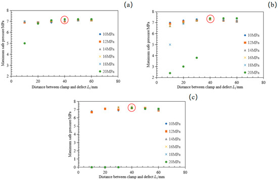
Figure 10.
Relation between maximum safe pressure of defective pipe and loading application distance. (a) The applied width is 10 mm. (b) The applied width is 20 mm. (c) The applied width is 30 mm.
3.3. Verification by the Results of Hydrostatic Pressure Test
Based on the aforementioned finite element analysis, the parameters of the pipe with artificial defects are ultimately determined as follows: outer diameter D of 219 mm, pipe thickness d1 of 6 mm, and length L of 700 mm. The pipe defects are artificially manufactured in accordance with the specifications provided in Table 3, with the L1 of 10 mm and L2 of 40 mm. The hydrostatic test is conducted following the designed three-stage pressurization procedure, as illustrated in Figure 11, and the recorded results are presented in Table 5.
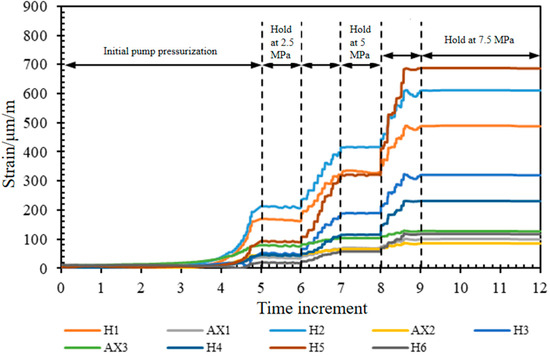
Figure 11.
Date of nine strain gauges.
Table 5.
Results of hydrostatic test results.
Experimental results demonstrated effective sealing performance at a medium pressure of 7.5 MPa, which exceeded the previously determined maximum safe pressure of 7 MPa without inducing pipe failure. This discrepancy arises because the study employed a conservative plastic failure criterion for theoretical predictions, whereas the experimental failure mechanism followed a less restrictive criterion, allowing normal operation at 7.5 MPa. As shown in Figure 11, with the continuous pressurization of the test pipe, the strain data measured by all strain gauges exhibited an upward fluctuating growth trend. These fluctuations are primarily caused by manual pressurization using a hand-operated test pump, while the overall increasing trend remained consistent with physical expectations. Under medium pressure of 7.5 MPa, the axial strains consistently exceed 200 μm/m, while circumferential strains remain below 200 μm/m. Among them, strain gauges H5 and H2, located at the central region of the device, recorded the highest strain values. Although strain gauges H1 and H3 are symmetrically positioned relative to H2 and theoretically subjected to identical loading conditions, the observed discrepancies in their readings are primarily caused by variations in bolt preload during installation. From the overall strain distribution perspective, the central region exhibited the maximum strain values within the entire structure.
To validate the reliability of the experimental results, finite element analysis is performed using three incremental loading steps. Strain values at all designated measurement points are selected for each loading step, and they are systematically compared with corresponding experimental data. Figure 12 presents the comparative results between experimental measurements and numerical simulations of the repair clamp under 2.5 MPa, 5.0 MPa, and 7.5 MPa medium pressure. The results demonstrate a good agreement between simulated and experimental strain at all pressure levels, with only slight discrepancies observed. These discrepancies may originate from the assumption of linear elastic material properties in the simulation, whereas the actual material exhibits elastoplastic behavior.
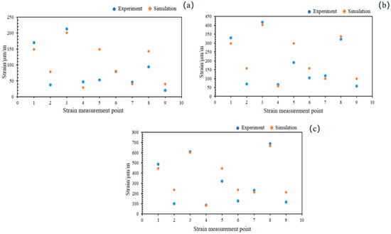
Figure 12.
Comparison of strain test and simulation at each point under various medium pressure Pm: (a) 2.5 MPa, (b) 5 MPa, (c) 7.5 MPa.
4. Conclusions
This paper presents a comprehensive study of a repair clamp designed for a D of 219 mm, with the following key conclusions:
(1) Finite element analysis (FEA) of the designed repair clamp’s sealing performance demonstrates that the rubber seal generates contact stresses consistently exceeding the medium pressure across the 5–20 MPa operational range, meeting sealing requirements.
(2) Sensitivity analysis of the pipe’s maximum safe pressure revealed that the critical condition occurs at a 6 mm and depth ratio of 0.8, corresponding to the minimum pressure resistance. Furthermore, when the repair clamp installation distance exceeded 40 mm, the maximum safe pressure exhibited a marginal decrease, whereas distances below 40 mm could significantly compromise pressure integrity. Therefore, when precise defect characterization is unattainable, a conservative approach should be implemented by positioning the repair clamp approximately 40 mm from the defect edge during maintenance operations.
(3) A hydraulic pressure test confirms the good sealing performance of the repair clamp, enabling the defective pipe to maintain normal operation under 7.5 MPa medium pressure. Comparative analysis between simulated and experimental strain data demonstrated good agreement across most measurement areas, with only minor discrepancies observed at localized points.
Author Contributions
The manuscript was written through the contributions of all authors. Investigation, conceptualization methodology, J.F.; conceptualization, funding acquisition, project administration, L.X.; methodology, investigation, X.S.; review and editing, methodology investigation, X.L.; review and editing, investigation, validation, funding acquisition, Y.S.; review and editing, methodology, formal analysis, H.W.; investigation, conceptualization, methodology, review and editing, Y.L. All authors have read and agreed to the published version of the manuscript.
Funding
This research was funded by the “Zhejiang Provincial Administration for Market Regulation Science and Technology Program, grant number ZC2023079”; the “National Natural Science Foundation of China, grant number 52305168”; and the “Science and Technology Program of Hangzhou, Zhejiang Province, grant number 20201203B159”.
Data Availability Statement
The datasets supporting the conclusions of this article are included within the article.
Conflicts of Interest
The authors declare no conflict of interest.
Appendix A
Appendix A.1

Figure A1.
Mesh sensitivity analysis: (a) seal component mesh; (b) defective pipeline mesh.
When the seal component mesh size is refined beyond 0.15 mm, the von Mises stress stabilizes, but the computational speed decreases by 50%. Therefore, a mesh size of 0.15 mm was selected and a defective pipe model with a mesh size of 10 mm was established.
References
- Sheets, C.; Shie, T.; Crawford, A. Thin-Wall pipe Repair: Evaluation of Reinforcement Systems and Internal Temperature Monitoring During Maintenance Procedures. In Proceedings of the 12th International Pipe Conference, Calgary, AB, Canada, 24–28 September 2018. [Google Scholar]
- Armando, R.; Ray, A. Deep water pipe emergencies, managing risk and cost, the coownership solution. In Proceedings of the 6th International Offshore Pipe Forum, Houston, TX, USA, 2 July 2011. [Google Scholar]
- Ossai, C.I.; Boswell, B.; Davies, I.J. Pipe failures in corrosive environments—A conceptual analysis of trends and effects. Eng. Fail. Anal. 2015, 53, 36–58. [Google Scholar] [CrossRef]
- Zhao, B.J.; Zhang, S.L.; Li, T.; Hao, J.L.; Wang, T.Y. The sealing technology in pipeline repair clamp. J. Coast. Res. 2020, 104 (Suppl. S1), 872–881. [Google Scholar] [CrossRef]
- Chuan, J.; Ma, Y.C. The design of high pressure clamp for plugging pipe under water. J. Ship. 2015, 32, 11–14. [Google Scholar]
- Zhao, B.J.; Zhu, H.; Zhang, S. Research of sealing property to subsea oil and gas pipe repair clamp. In Proceedings of the Pressure Vessels and Piping Conference, Boston, MA, USA, 19–23 July 2015. [Google Scholar]
- Djukic, L.P.; Sum, W.S.; Leong, K.H.; Hillier, W.D.; Eccleshall, T.W.; Leong, A.Y.L. Development of a fibre reinforced polymer composite clamp for metallic pipe repairs. Mater. Des. 2015, 70, 68–80. [Google Scholar] [CrossRef]
- Hao, X.; Yun, F.; Jiao, K.; Chen, X.; Jia, P.; Wang, X.Y.; Wang, L.Q. Mechanical Behavior and Sealing Performance Study of Subsea Connector Core-Sealing Components under the Combined Action of Internal Pressure, Bending Moment, and Axial Load. J. Mar. Sci. Eng. 2023, 11, 1691. [Google Scholar] [CrossRef]
- Wei, Z.; Wang, L.; Guan, Y.; Yao, S.; Li, S. Static metal sealing mechanism of a subsea pipe mechanical connector. Adv. Mech. Eng. 2016, 8, 1687814016654821. [Google Scholar] [CrossRef]
- Sum, W.S.; Leong, K.H.; Djukic, L.P.; Nguyen, T.K.T.; Leong, A.Y.L.; Falzon, P.J. Design, testing and field deployment of a composite clamp for pipe repairs. Plast. Rubber Compos. 2016, 45, 81–94. [Google Scholar] [CrossRef]
- Cao, X.W.; Zheng, Z. Design of the graphite sealing based repair clamp for subsea pipes. Oil Gas Storage Transp. 2019, 38, 467–471. [Google Scholar]
- Khotsianovsky, A. Material Strength and Applied Mechanics; IOS Press: Amsterdam, The Netherlands, 2023; pp. 143–149. [Google Scholar]
- Zhao, B.; Zhang, S.; Gao, Q.; Miao, C.; Wang, T. Optimization of sealing parameters of double-sealing pipe repair clamp. J. Theor. Appl. Mech. 2022, 60, 333–346. [Google Scholar] [CrossRef]
- Alnaser, I.A.; Yunus, M.; Alfattani, R.; Alamro, T. Multiple-output fracture characteristics optimization of bi-material interfaces for composite pipe repair using swarm intelligence technique. J. Fail. Anal. Prev. 2021, 21, 507–517. [Google Scholar] [CrossRef]
- Zhang, P.; Gong, C.; Wu, Q.; Zeng, C. Experimental Study on the Bearing Capacity of Reinforced Concrete Pipes with Corrosion-Thinning Defects Repaired by UHP-ECC Mortar Spraying. Appl. Sci. 2023, 13, 7800. [Google Scholar] [CrossRef]
- Zhao, B.J.; Zhang, S.L.; Gao, Q.J.; Miao, C.L.; Wang, T.Y. Numerical Study on Tooth Angle Optimization of Enhanced Structure for Subsea pipe Repair Clamp. Str. Mater. 2022, 54, 309–317. [Google Scholar]
- Ma, Y.; Fan, T.; Zhang, Q. Experimental and numerical simulation of a novel on-line leak sealing technology based on magnetorheological adhesive. Process Saf. Environ. Prot. 2025, 195, 106731. [Google Scholar] [CrossRef]
- Zhao, Z.; Shi, X. Analysis on Contact Pressure for the Seal Structure of Repair Clamp with Wedge Contact Seals. J. Phys. Conf. Ser. 2024, 2920, 012024. [Google Scholar] [CrossRef]
- Zhang, X.; Fang, H.; Shi, M.; Du, M.; Yang, K.; Li, B.; Zhang, Z. Structural performance of corroded concrete pipes after mortar spraying rehabilitation under traffic load. Tunn. Undergr. Space Technol. 2022, 128, 104620. [Google Scholar] [CrossRef]
- Fekete, G.; Varga, L. The effect of the width to length ratios of corrosion defects on the burst pressures of transmission pipes. Eng. Fail. Anal. 2012, 21, 21–30. [Google Scholar] [CrossRef]
- He, T.; Duan, M.; An, C. Prediction of the collapse pressure for thick-walled pipes under external pressure. Appl. Ocean Res. 2014, 47, 199–203. [Google Scholar] [CrossRef]
- Mazurkiewicz, L.; Tomaszewski, M.; Malachowski, J.; Sybilski, K.; Chebakov, M.; Witek, M.; Yukhymets, P.; Dmitrienko, R. Experimental and numerical study of steel pipe with part-wall defect reinforced with fibre glass sleeve. Int. J. Press. Vessel. Pip. 2017, 149, 108–119. [Google Scholar] [CrossRef]
- Liu, H.F.; Duan, M.L.; Wang, Y.Y.; Yu, Z.D.; Yu, Y.; Sun, C.G. Influence of length-diameter ratio on collapse of subsea pipe using the subsea repair clamp. China Pet. Mach. 2017, 45, 117–120. [Google Scholar]
- Zhang, K.; Geng, T.; Yang, J.; Ma, R. Simulating the sealing performance of the double rubber cylinder assembly in an intelligent pipeline isolation tool. Proc. Inst. Mech. Eng. Part C J. Mech. Eng. Sci. 2024, 238, 7812–7829. [Google Scholar] [CrossRef]
- VijayaKumar, S.D.; Lo, M.; Karuppanan, S.; Ovinis, M. Failure Pressure Prediction of Medium to High Toughness Pipe with Circumferential Interacting Corrosion Defects Subjected to Combined Loadings Using Artificial Neural Network. Appl. Sci. 2022, 12, 4120. [Google Scholar] [CrossRef]
- Zhang, S.L.; Zhao, B.J.; Liao, C.L.; Wang, T.Y.; Li, T. Affecting Parameters of Sealing Capacity of Subsea Oil and Gas pipe Repair Clamp. China Offshore Plat. 2021, 36, 85–90. [Google Scholar]
- Xu, P.; Qu, C.; Yao, S.; Yang, C.; Wang, A. Numerical Optimization for the Impact Performance of a Rubber Ring Buffer of a Train Coupler. Machines 2021, 9, 225. [Google Scholar] [CrossRef]
- Ramezani, M.A.; Yousefi, S.; Fouladi, N. An experimental and numerical investigation of the effect of geometric parameters on the flexible joint nonlinear behavior for thrust vector control. Proc. Inst. Mech. Eng. Part G J. Aerosp. 2019, 233, 2772–2782. [Google Scholar] [CrossRef]
- Ma, Y.; Lei, G.; Hu, Q.S.; Liu, B.Q. Thermal stress and sealing performance analysis of variable-section rubber seals based on Abaqus. Lubr. Eng. 2019, 44, 112–116. [Google Scholar]
- Dong, S.X.; Wang, S.H.; Chen, W.J.; Zhai, H.D.; Zhou, X.J. Optimization of compression ratio for O-rings used in packers. Lubr. Eng. 2019, 44, 151–155. [Google Scholar]
- GB/T 17395-2024; Dimensions, Shapes, Masses and Tolerances of Steel Tubes. Standards Press of China: Beijing, China, 2024.
- ASME B31.3-2022; Process Piping. American Society of Mechanical Engineers: New York, NY, USA, 2022.
- Mehditabar, A.; Razmkhah, S.; Sadrabadi, S.A.; Peng, X.; Yuan, S.; Abot, J.L. Three-dimensional thermoelastic analysis of a functionally graded truncated conical shell with piezoelectric layers. Int. J. Comput. Mater. Sci. Eng. 2023, 12, 2350003. [Google Scholar] [CrossRef]
- Sadrabadi, S.A.; Rahimi, G.H. Yield onset of thermo-mechanical loading of FGM thick walled cylindrical pressure vessels. Int. J. Mech. Aerosp. Ind. Mechatron. Eng. 2014, 8, 1317–1321. [Google Scholar]
- Abtahi, S.M.R.; Sadrabadi, S.A.; Rahimi, G.H.; Singh, G.; Abyar, H.; Amato, D.; Federico, L. Experimental and Finite Element Analysis of Corroded High-Pressure Pipeline Repaired by Laminated Composite. Comp. Model. Eng. Sci. 2024, 140, 1783–1806. [Google Scholar] [CrossRef]
- GB/T 20801.1-2020; Pressure Piping Code—Industrial Piping—Part 1: General. Standards Press of China: Beijing, China, 2020.
- ASME B31G-2012; Manual for Determining the Remaining Strength of Corroded Pipelines. American Society of Mechanical Engineers: New York, NY, USA, 2012.
Disclaimer/Publisher’s Note: The statements, opinions and data contained in all publications are solely those of the individual author(s) and contributor(s) and not of MDPI and/or the editor(s). MDPI and/or the editor(s) disclaim responsibility for any injury to people or property resulting from any ideas, methods, instructions or products referred to in the content. |
© 2025 by the authors. Licensee MDPI, Basel, Switzerland. This article is an open access article distributed under the terms and conditions of the Creative Commons Attribution (CC BY) license (https://creativecommons.org/licenses/by/4.0/).