Article

A Flexible Frequency-Coded Electromagnetic Sensing Array for Contactless Biological Tissues Health Monitoring

1
Department of Information Engineering, University of Pisa, 56122 Pisa, Italy
2
Consorzio Nazionale Interuniversitario per le Telecomunicazioni (C.N.I.T.), 56124 Pisa, Italy
3
Free Space s.r.l., via Antonio Cocchi 7, 56121 Pisa, Italy
*
Author to whom correspondence should be addressed.
Appl. Sci. 2025, 15(16), 9015; https://doi.org/10.3390/app15169015
Submission received: 30 July 2025 / Revised: 10 August 2025 / Accepted: 12 August 2025 / Published: 15 August 2025
(This article belongs to the Section Electrical, Electronics and Communications Engineering)

Abstract

In this study, we present a wearable sensing system for monitoring the physiological status of damaged biological tissues based on a flexible, frequency-coded electromagnetic spiral resonator array. The physiological parameter evaluation is performed in a contactless way, avoiding the placing of electronically active elements directly upon the patient’s skin, thus ensuring safety and comfort. Firstly, we report in detail the physical principles behind the sensing strategy: a passive array is interrogated through an actively fed external single-loop probe that is inductively coupled with the double-layer spiral unit cells. The variation in the physiological parameters influences the array response, thus providing sensing information, due to the different complex dielectric permittivity values related to the tissue status. Moreover, the proposed frequency-coded approach allows for spatial information on the lesion to be retrieved, thus increasing the sensing ability. In order to prove the validity of this general methodology, we created a numerical test case, designing a practical implementation of the wearable sensing system working at a radiofrequency regime (10–100 MHz). In addition, we also fabricated prototypes, exploiting PCB technology, and realized stratified phantoms by incorporating opportune additives to control the dielectric properties. The numerical results and the experimental verification demonstrated the validity of the developed sensing strategy, showing satisfying agreement and, thus, proving the good sensibility and spatial resolution of the frequency-coded array. These results can open the path to a radically novel approach for self-care and monitoring of inflamed status and, more generally, for wearable sensing devices in biomedical applications.

1. Introduction

In the past few decades, several medical achievements and improvements have been made possible thanks to the technological development of innovative clinical equipment. Among this wide class, sensing devices are fundamental to monitoring pathological parameters or performing imaging procedures [1,2,3]. Due to their large impact in the clinical environment, a lot of effort, both in research and industry, has been expended to develop wearable devices to increase patients’ comfort and to enhance monitoring effectiveness [4,5,6,7,8]. In addition to sensing performance, wearability has the potentiality to also tackle the technological challenge of “self-monitoring”, which is advantageous in terms of reduced healthcare costs [1,9,10,11,12]. A smart wearable system for tissue health monitoring is generally composed of a wearable bandage in which one or more sensors are opportunely integrated. The signals coming from these sensors are usually sent to a wireless reading device (such as a smartphone) via an antenna placed inside the bandage and connected to them [13,14,15,16]. In this way, the patient can provide data to the physician, who remotely monitors the physical status of the investigated tissue, avoiding unnecessary travel and hospitalization.
Unsurprisingly, several technical solutions were developed and presented within the scientific community. Generally, smart bandages include active sensing components fed with a battery, such as pH, temperature [5] and various chemical sensors and electrodes [17,18]. However, active components are dangerous for patients and require periodic maintenance, especially for battery replacement. Lastly, the costs and the instrumentation requirements for active elements are usually non-negligible, especially when considering the widespread implementation of this solution [19].
To overcome these limits, we herein investigate the use of a specifically designed electromagnetic passive spiral resonators array [20,21,22]. Planar arrays are specifically engineered structures able to control and manipulate an electromagnetic field according to its application. Due to their reduced electrical thickness, planar arrays are generally easy to integrate into electronic systems and can also be created with flexible materials, thus enabling conformal and wearable applications. Especially in the clinical environment, device flexibility and biocompatibility are key aspects of patient comfort. For these reasons, planar arrays and metasurfaces in general are already extensively employed in biomedical applications, to enhance the signal-to-noise ratio in magnetic resonance imaging (MRI) and microwave imaging (MWI) and increase the efficiency and the working distance in Wireless Power Transfer (WPT) [23,24,25,26], as well as for use in consumer wireless devices [27,28]. Moreover, electromagnetic metasurfaces have also proven useful in directly monitoring physiological signals [29]. To mention a few examples, systems capable of detecting motions to prevent falls among elderly people and identifying asthma have been proposed, generally employing an actively fed phased array.
Hence, to further improve the actual state of the art, we propose a passive, frequency-coded and flexible spiral resonator array that is suitable for biomedical sensing applications. The array can be wrapped around any anatomical district, and it is made of a matrix of opportunely designed radiofrequency spiral resonators (SRs) [30,31,32,33,34]. The passive array can be interrogated through an actively fed single-loop probe and inductively coupled with all the unit cells. Considering the benefits of maximizing the unit cells’ Q-Factor for near-field sensing applications, they were designed by connecting two spiral resonators in series, in opposite winding directions [35,36]. The self-resonance properties of the SRs make them extremely sensitive to changes in the dielectric properties of the tissues, which can be, in turn, correlated to the physiological status [37]. Indeed, it is known from the literature that different values of dielectric properties characterize healthy and pathological tissues, mainly due to their different water and ion contents [38,39]. Further, to obtain spatial localization, the conceived array peculiarity relies on the fact that the unit cells are frequency coded, i.e., each SR has a different resonant frequency. In this way, it is possible to simultaneously interrogate each unit cell, codifying the spatial localization.
To the best of our knowledge, this is the first time that a frequency-coded, flexible array is employed for sensing applications in a biomedical environment. In order to verify our approach and the potential performance, we first conceived a numerical test case, performing accurate simulations on a representative biological model for different inflammation states. After that, we fabricated the prototypes and prepared the phantoms to be measured, accurately replicating the numerical model in terms of structure and dielectric characteristics.
The remainder of this paper is organized as follows. Section 2 presents the theoretical aspects behind the proposed sensing solution. Further, the numerical test case CAD models and the corresponding fabricated prototypes are described, also providing a detailed explanation of the phantom preparation procedure. Section 3 reports both the simulated and the experimental results, while some discussions are developed in Section 4.

2. Materials and Methods

2.1. Physical Background

The proposed system is composed of a passive array made of a 2 × 2 matrix of double-layer spiral resonators, inductively coupled with an external probe loop (Figure 1). The probe loop is not resonating, and it excites and collects the output signal from the array. In more detail, the probe loop is placed close to the array and, by simultaneously scanning all the unit cells, information about the investigated tissue can also be extracted from a spatial point of view through the frequency codification.
The equivalent circuital model representing the elementary architecture composed of the probe loop and a single unit cell is described in [40] and shown in Figure 2. To enable the array to spatially localize information, the frequency encoding strategy is implemented across its N resonating unit cells. Each spiral resonator presents a distinct resonant frequency, achieved through careful tuning of its geometric parameters. It is essential that the frequency differences among the unit cells remain sufficiently small to preserve the intended interaction with the probe loop but large enough to minimize electromagnetic coupling between neighboring unit cells. Under these two conditions, the proposed design enables spatially resolved and independent identification of tissue properties across the array. The corresponding probe loop input impedance can be formulated as below:
Z i n p u t = R l o o p + j ω L l o o p + i = 1 N ω 2 M l o o p S R i 2 R S R i + j ω L S R i + 1 j ω C S R i ,
where R l o o p and L l o o p represent the probe loop resistance and inductance, while R S R i , L S R i and C S R i quantify the i-th spiral resonator resistance, inductance and capacitance. Because of the mutual interaction between the i-th unit cell and the probe loop (indicated by M l o o p S R i ), tissue status information can be inferred by reading the input impedance (1). As already explained, tissue dielectric properties are correlated with health conditions. In turn, the spiral resonator behavior depends on the investigated region’s permittivity and electrical conductivity.
To quantify the system behavior as a function of the tissue dielectric properties, an analytical model is herein presented. We can suppose that the conformal array is wrapped around a certain anatomical district. From an electrical point of view, the tissue can be considered semi-infinite in thickness. Therefore, the array is backed by the tissue on one half-space, while, on the other side, free space can be identified. Consequently, the effective permittivity experienced by the unit cells ( Ɛ e f f ) can be calculated as the average value between the complex dielectric permittivity of the tissue (related to its physiological status) and that of the free space. The effective complex permittivity directly influences the capacitive behavior of each spiral resonator ( C S R in (1)) by multiplying the free space capacitance value.
Since biological tissues are lossy other than dispersive, both the real and imaginary parts of the permittivity are added to the SR RLC circuital model, which are a function of the tissue status:
R e f f = R S R + Ɛ e f f ω C S R 0 ( Ɛ e f f 2 + Ɛ e f f 2 ) C e f f = C S R 0 ( Ɛ e f f 2 + Ɛ e f f 2 ) Ɛ e f f ,
The two effective quantities R e f f and C e f f substitute R S R and C S R in (1), representing the dependance of the probe loop input impedance on the tissue properties. Instead, C S R 0 is the SR free space capacitance. From a physical point of view, the loss component of the complex effective permittivity ( Ɛ e f f ) is responsible for a larger resistance in the circuital model of the SR. This causes a magnitude reduction in the probe loop input impedance peak value, evaluated at the SR resonance. Conversely, the real term of the complex permittivity ( Ɛ e f f ) is responsible for the change in the unit cell resonant frequency.
As a matter of fact, an increasing level of tissue inflammation involves a progressively higher water and ion concentration induced by the blood local over-perfusion condition, responsible for influencing both the complex permittivity components. In a practical scenario, the loss component is significantly more influential on the probe loop response than the dielectric permittivity real part. Indeed, conductivity experiences a larger variation compared to the real part of the effective dielectric permittivity for different inflammation states. Therefore, in the remainder of this study, we will consider the amplitude variations in the probe loop input impedance as the control quantity to infer the tissue health condition.
Finally, since the envisioned application is related to clinics, the wearability of the array has been considered as an added value for patient comfort. Therefore, the array should be fabricated with flexible material to be anatomically conformal.

2.2. Numerical Design

To validate the proposed approach, we conceived a numerical set-up by employing an electromagnetic full-wave software based on the Finite Element Method (CST Studio Suite, Simulia, Dassault Systemes, Vélizy-Villacoublay, France). The set-up dimensions were selected considering the final destination of the proposed technology, i.e., a smart bandage for injured tissue region monitoring. The design is, in principle, scalable to other districts and dimensions.
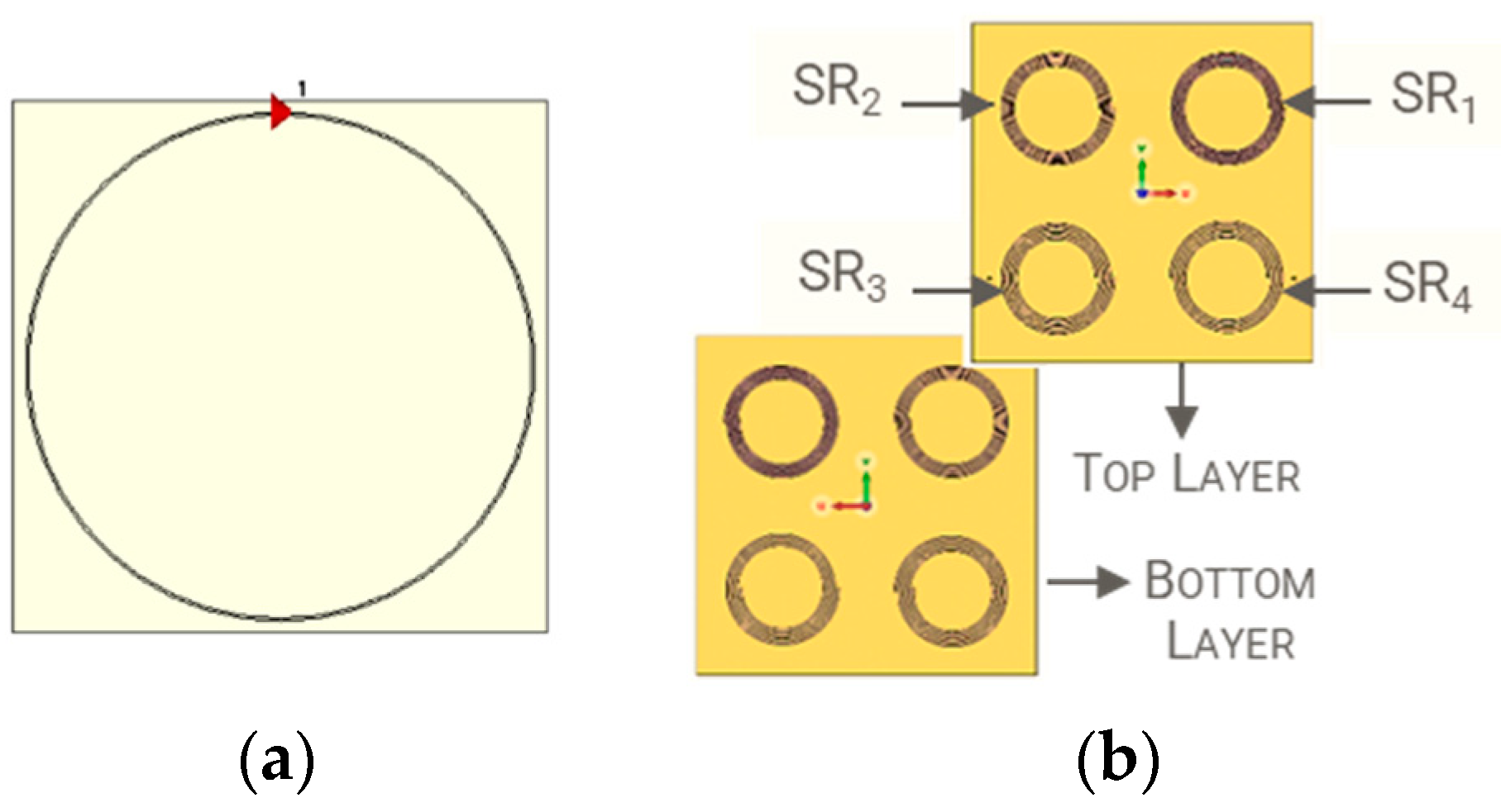
The exploited physical concept for the sensor design relies on the mutual coupling between the fed external loop, acting as the interrogator, and the passive spiral resonator, placed in its immediate vicinity and constituting a single unit cell of the array. Therefore, we first focused on the external active probe design, realized as a one-turn, 6.5 cm radius loop, etched with a 35 µm thick and 0.7 mm width copper strip. Conversely, the substrate material consists of a 0.8 mm thick FR4 (εr = 4.3, tanδ = 0.02) (Figure 3a). The geometrical properties and the fabrication materials are also summarized in Table 1.
The active probe self-resonance, caused by its parasitic capacitance, was around 300 MHz. Notably, it must be kept away from the sensing operating frequency range to ensure the validity of the condition reported in (1). Instead, the array sensing unit cells are made of two passive spiral resonators (SRs) with opposite winding directions and connected in series via through-holes. By choosing the double-layer geometric configuration, the total coil resistive contribution R S R is double compared to the single-layer configuration. However, the inductance undergoes a 4-fold increase, since it is dependent on the square of the spiral turns number. Thus, the double-layer configuration leads to a significant quality factor enhancement and, thus, in the sensitivity of the system [36]. Considering our particular application, the principal technological challenge to face is related to the combination of compact dimensions, relatively low operative frequency (around 60 MHz), high sensitivity and good spatial resolution. Therefore, as a compromise among these features, we selected a unit cell external radius equal to 20 mm, obtaining the opportune self-resonance frequency by progressively adapting the various SR geometric characteristics, including the number of turns and the pitch. As mentioned, the fundamental aspect of the proposed solution relies on the frequency coding of each unit cell. This choice amplifies the array abilities, making each unit cell response uniquely recognizable and spatially localizable during the externally fed single-loop probe interrogation. In particular, the final unit cell design is reported in Figure 3b, whereas the geometrical and material properties are listed in Table 1. The final 2 × 2 array is then achieved covering a 12 cm × 12 cm area of a 127 µm thick ISOLA substrate (εr = 3.45, tanδ = 0.0015).
Since the envisioned application of the proposed sensing system is a wearable device, the last design step was directed to make the planar array conformal to a cylindrical shape. The cylinder radius was chosen equal to 40 mm, in order to simulate the wrapping around a human forearm. In Figure 4, the planar (Figure 4a) and conformal (Figure 4b) versions of the array are depicted.
In Table 2, the resonant frequency values of each unit cell for both planar and conformal configurations are reported. As evident from Figure 4b, the unit cells change shape due to the bending process. This leads to a corresponding variation in the RLC circuit parameters associated with each spiral and, consequently, a different resonant frequency [40].
The bending process mainly causes an increase in the coil pitch, therefore leading to an upshift in the resonance frequency. It is worth pointing out that all the resonant frequency values reported in Table 2 are considered without biological load. Conversely, the presence of the phantom causes a decrease in these values due to the relatively high dielectric permittivity of human tissues.
Thus, to carry out a numerical analysis considering a more realistic scenario, a layered cylindrical phantom with a base radius of 40 mm and a height of 200 mm was included in the model to mimic a human arm. The simplified model consists of an external 2 mm thick skin layer and an internal muscle volume. The sensing array was conformally bent around the cylinder and placed 1 mm distant from its surface. Finally, the probe loop was positioned 5 mm above the array, as shown in Figure 5a. With the aim of evaluating the system sensitivity in monitoring tissue physiology, two different scenarios were investigated. In the first configuration, the phantom model was divided into four sub-regions, each corresponding to one of the four resonant elements. The dielectric properties of each portion, in terms of permittivity and conductivity, were assigned according to the healthy tissue’s properties at the specific operating frequency. The corresponding values were derived from [39] and are listed in Table 3.
On the other hand, the second scenario aims at assessing the sensing performance in the presence of different inflammation states. In detail, three of the four regions were maintained unaltered in healthy condition, whereas the fourth one was selected to represent a pathological tissue, characterized by a progressively more severe level of inflammation (Figure 5b). A worsening of the inflammatory severity leads to an increase in the concentration of water and electrolytes [41]. We simulated three distinct inflammatory conditions (G1: slight inflammation, G2: moderate inflammation, G3: severe inflammation) by raising the permittivity and conductivity values by 15% for each stage (at the operating frequency of the fourth SR). The finally adopted dielectric properties for pathological tissue are reported in Table 4.

2.3. Experimental Fabrication

Based on the geometrical characteristics and material properties previously discussed, a prototype of the radiative sensing system was manufactured by exploiting Printed Circuit Board (PCB) technology. In particular, a rigid 0.8 mm thick FR-4 substrate was employed for the probe loop (refer to Figure 6a), whereas flexible ISOLA sheet with a thickness of 0.127 mm was selected for the double-layer spiral resonator array (refer to Figure 6b). The chosen thickness for the array realization provides extreme flexibility, allowing the conformability around the desired anatomical district. By connecting the probe loop to a calibrated VNA (N9918A FieldFox, Keysight, Santa Rosa, CA, USA) through a micro-SMA connector [42], experimental measurements were carried out. Specifically, the complex input impedance of the probe loop was recorded with 1001 frequency points on a linear scale over a frequency range 10–170 MHz.

2.4. Homogeneous Phantom Fabrication and Dielectric Characterization

The final preparatory step consisted of realizing the biological phantoms, thus reproducing conditions mimicking a realistic scenario. According to the numerical analysis, four different types of phantoms have been fabricated, replicating the dielectric properties of healthy soft tissue and its progressive inflammation states (indicated as G1, G2 and G3).
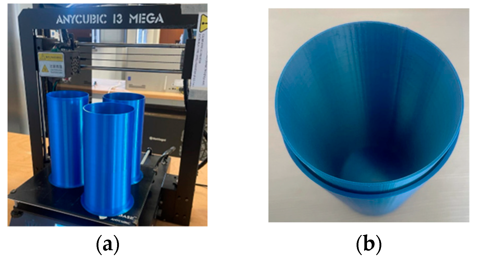
The supporting structure for phantom realization was manufactured in polylactic acid (PLA) by exploiting 3D-printing technology (Anycubic I3 Mega, Anycubic, Shenzhen, China) and represented in Figure 7a. It comprises a fixed outer cylinder and a removable inner pipe, designed to facilitate its extraction and ensure the formation of both the skin-like layer and the internal muscle region (refer to Figure 7b). The external cylinder was provided with a thick and robust base, equipped with a runner for fixing the inner pipe (see Figure 7c), thus preventing any unintended leakage of fluid. Table 5 provides the final supporting structures’ geometrical dimensions.
To simplify the procedure, the dielectric properties of the healthy biological sample were determined as the average value of both permittivity and conductivity from the data provided in Table 3. The phantom composition was obtained by combining commercially available, non-toxic, and inexpensive materials: deionized water, agar, glycine (C2H5NO2) and sodium chloride (NaCl). In this study, a 2% w/v agar-based solution was selected to reproduce the tissue-equivalent phantom model [43].
Agar powder was employed as the jellifying material because it represents a suitable environment for adding fillers [44]. Furthermore, agar-based models exhibit versatility, simplicity of manufacturing, and density comparable to that of human soft tissue [45]. To allow for the control of dielectric properties, fillers and deionized water (solvent) were added, creating a homogeneous liquid mixture. In this regard, different works investigated the correlation between salt concentration and resulting conductivity in a wide frequency range [44,46,47]. Conversely, adjusting the phantom dielectric permittivity for mimicking a specific tissue at a certain frequency is not well explored in the literature. Artificial additives, such as aluminum powder [44], polyvinylpyrrolidone [48] and polyethylene powder [43], were all proposed to modulate the dielectric permittivity real part. Nevertheless, the incorporation of these synthetic ingredients into the agar solution is often hindered, necessitating the addition of thickeners like TX-151, indirectly affecting the overall dielectric properties [43]. Furthermore, it is rather common for stratification and sinking events to occur during the preparation procedure [44]. A valid alternative is represented by natural additives, such as sugar (sucrose) and glycine, which can be easily employed to tune the real part of the complex relative permittivity [46,49,50]. As our dielectric phantom models require a permittivity value higher than that of water, glycine was chosen as a filler.
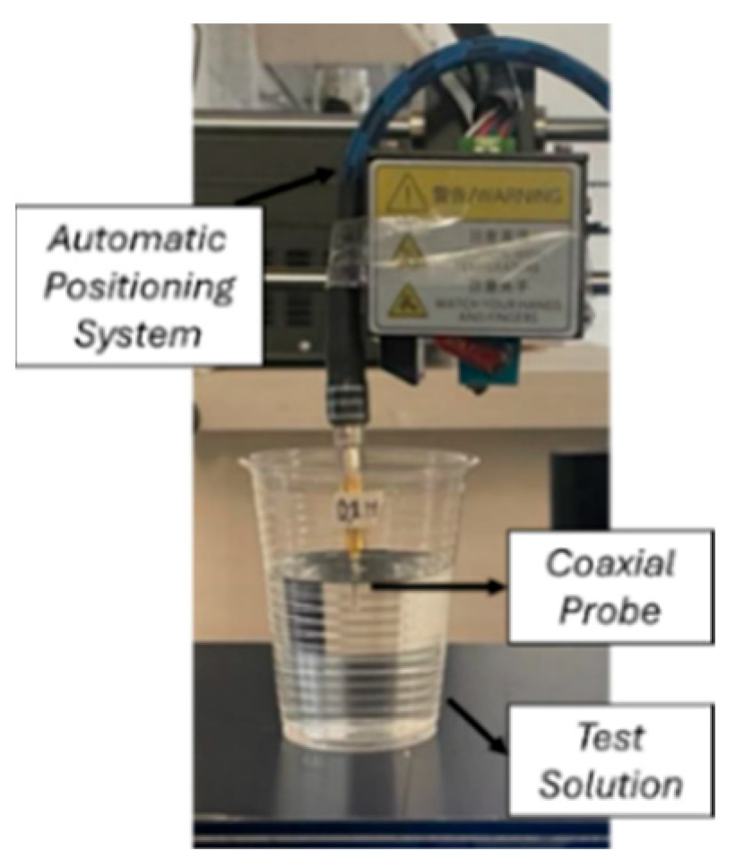
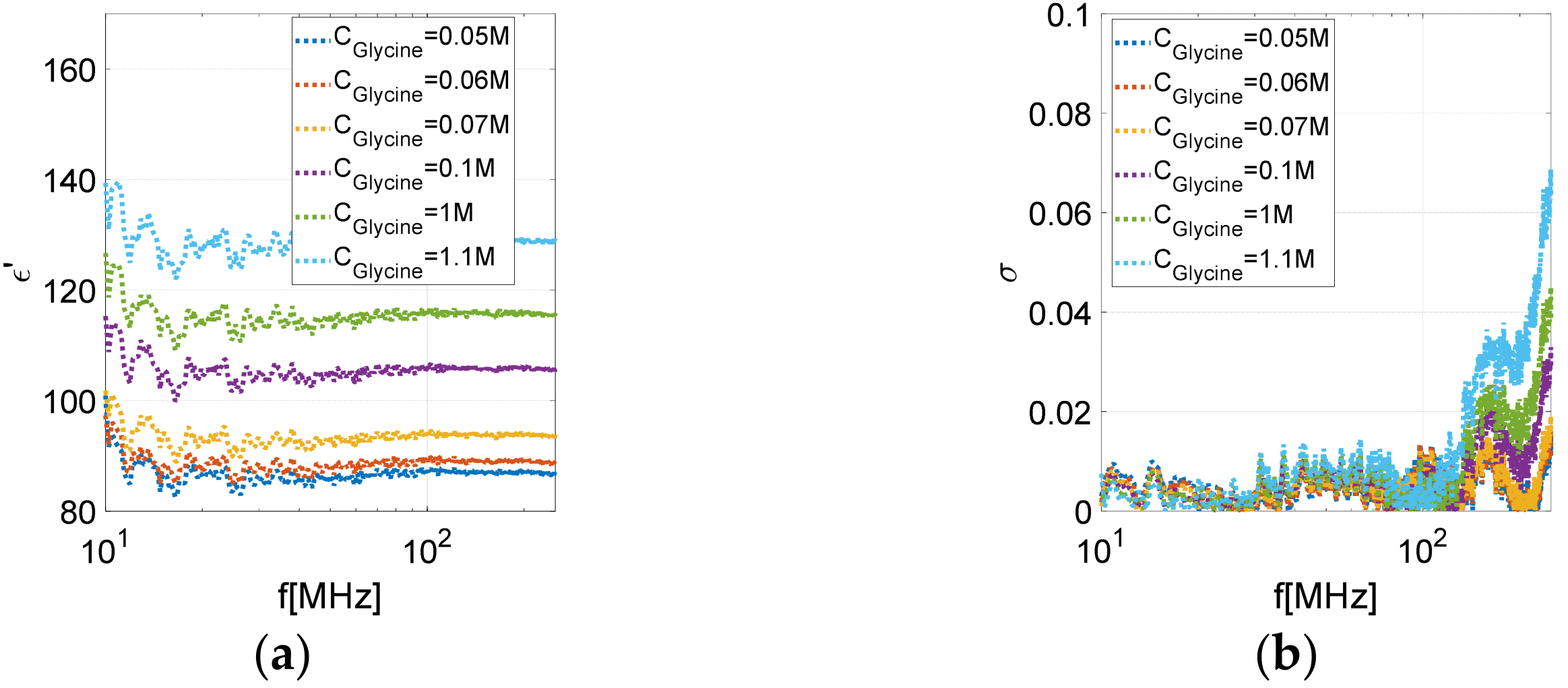
Therefore, we prepared six water-based solutions with progressively higher concentrations of glycine and an equal batch with progressively higher concentrations of NaCl. By adopting an open-ended coaxial probe system (Figure 8), the dielectric properties of each sample were experimentally validated. The reflection coefficient was measured for each sample over the frequency range 10 MHz–250 MHz, by using a calibrated VNA (N9918A FieldFox, Keysight, Santa Rosa, CA, USA) [42]. Figure 9 depicts the permittivity and conductivity, as a function of frequency, resulting from the characterization procedure. In more detail, Figure 9a shows the correlation between the rise in dielectric permittivity and glycine concentration, whereas the conductivity turns out not to be significantly affected by the additive within the specified frequency range (Figure 9b). Conversely, regarding salt, we obtained increasing levels of conductivity with its progressive addition, while the permittivity values remain nearly constant, as shown in Figure 9c,d. These outcomes are highly significant since they indicate that, within the desired frequency range, each additive is almost independently responsible for the modification of a single control parameter. Figure 10 illustrates the glycine concentration–permittivity (a) and salt concentration–conductivity (b) relationships, based on experimental data extracted at 100 MHz. In particular, the quadratic polynomial Linear Model Poly2 from Matlab® 2019 software was adopted to fit the data, whose formulation is below reported. The coefficients calculated within a 95% confidence bound are reported in Table 6.
F ( x ) = a x 2 + b x + c
By altering the proportion of NaCl and glycine within the mixture, we were able to manipulate the dielectric characteristics to mimic distinct stages of muscle tissue inflammation. To ensure simplicity in creating the phantom, the skin layer was also consistently assumed to be in a healthy condition for the inflamed muscle tissue samples. Therefore, to realize the three progressive levels of muscle inflammation (G1, G2 and G3), three corresponding aliquots, each measuring approximately 400 mL, were realized by starting from the healthy muscle-like liquid portion.
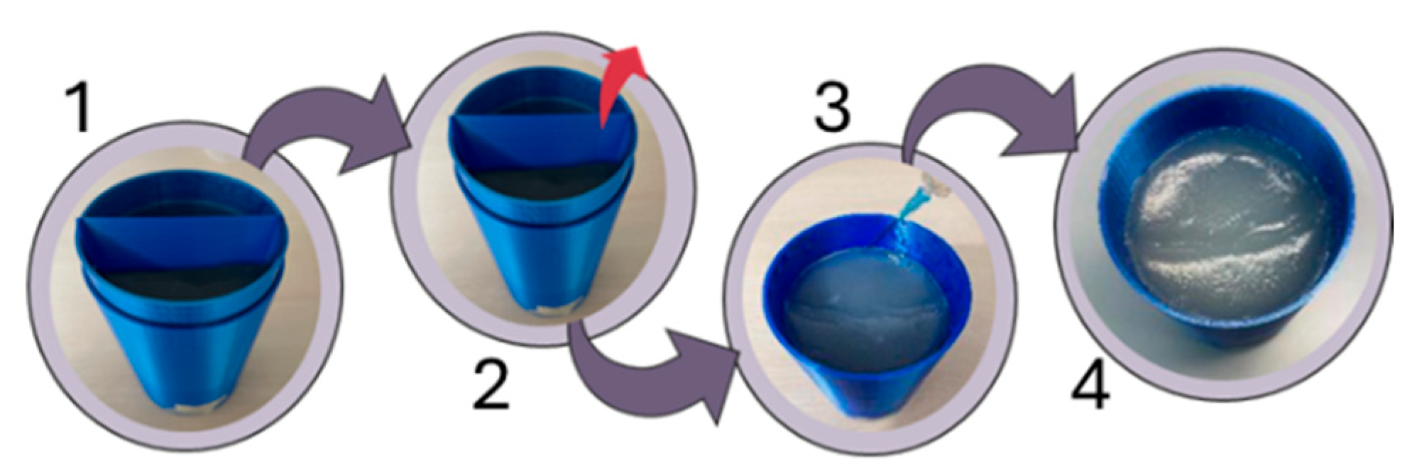
The different homogeneous mixtures (mimicking the healthy skin, healthy muscle, and the three degrees of muscle inflammation) were accurately poured into 3D-shaped molds still in liquid phase. First, to replicate the absence of inflammation (reference case), we filled the internal cylinder of the corresponding 3D model (refer to Figure 7b) with the healthy muscle-like fluid. In addition, we replicated the distinct conditions of injured tissue by pouring the G1, G2 and G3 liquid phases into the three supporting structures (see Figure 7d). Specifically, the casting of the fluid reproducing the inflammatory state was limited to one-fourth of the overall volume, remaining confined thanks to the middle splitter. After rapid cooling at 4 °C, aimed at starting the polymerization phase, we filled the remaining three-quarters of the inner volume, for each inflamed model, with healthy muscle-like fluid. This initial solidification prevented the merging of fluids with different dielectric characteristics. We provided a second rapid cooling stage at the same temperature to complete the solidification process of the overall phantoms. Once the phantoms reached a satisfying degree of polymerization, characterized by a liquid-gelatinous consistency, we proceeded to remove the inner cylinders from the support structures. This enables the addition of the skin layer and improves the bonding of the different regions inside the phantom, minimizing air gaps. Successively, for each of the four phantom models, the skin liquid component was injected into the tiny cavity formed between the muscle region and outer cylinder by utilizing a syringe. Finally, we carried out a long cooling process at 4 °C, ensuring the complete solidification of the phantom models. Figure 11 provides an overview of the steps involved in the phantom preparation process.

3. Numerical and Experimental Results

3.1. Numerical Simulations

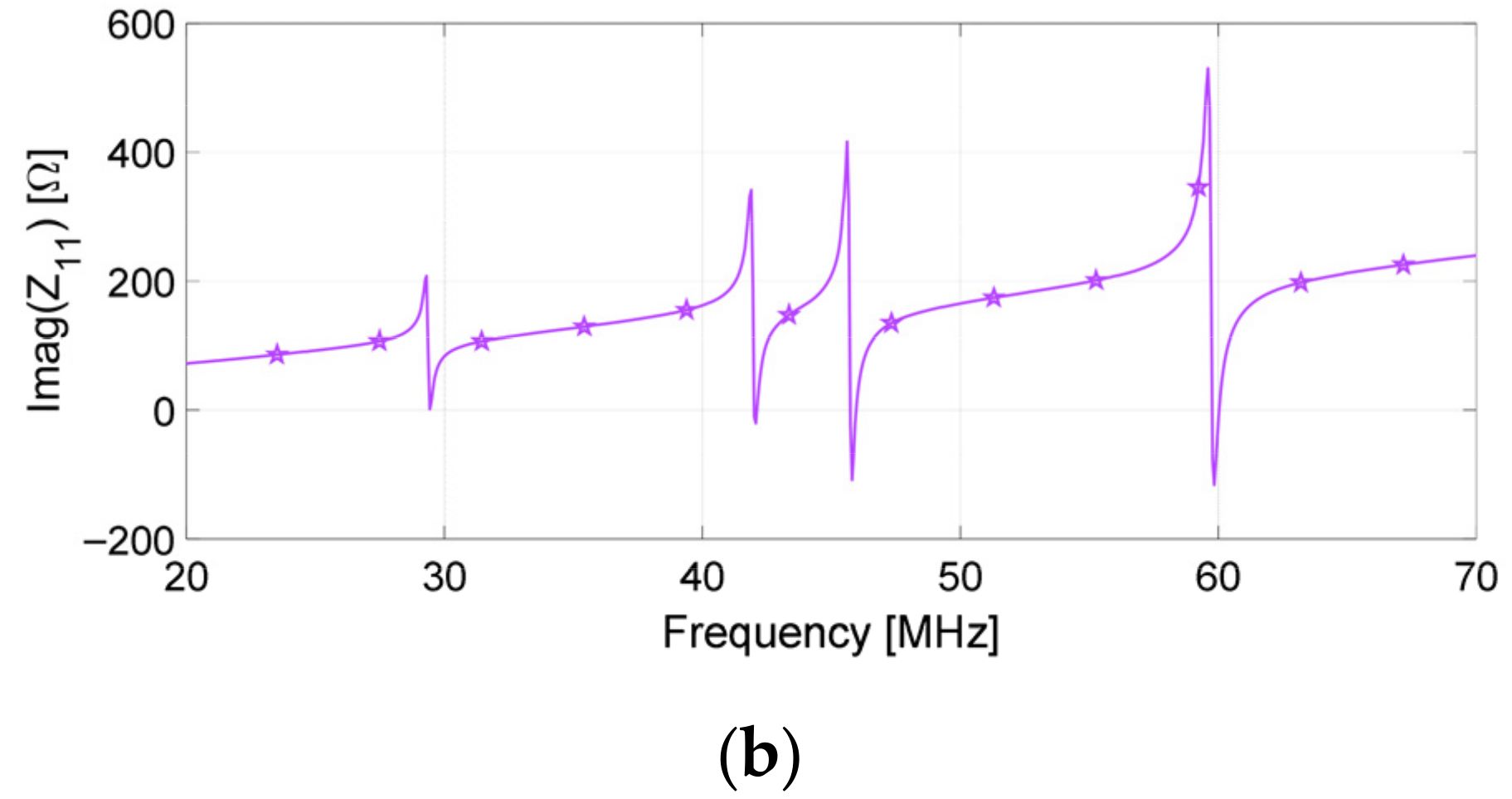
We preliminary evaluated the probe loop input impedance when the double-layer spiral resonator array is placed 5 mm beneath it in a planar configuration and without any biological phantom. As reported in Figure 12, the input impedance reveals four distinct peaks, each corresponding to the resonance of each unit cell, within the desired frequency range.
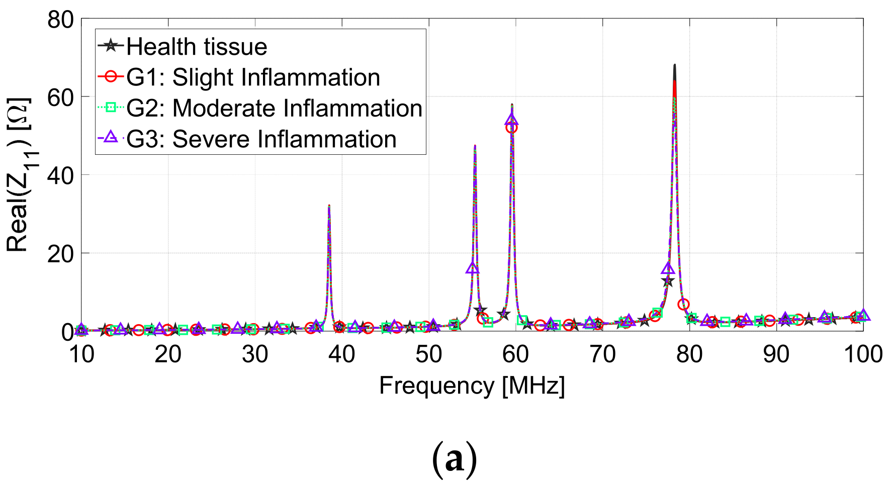
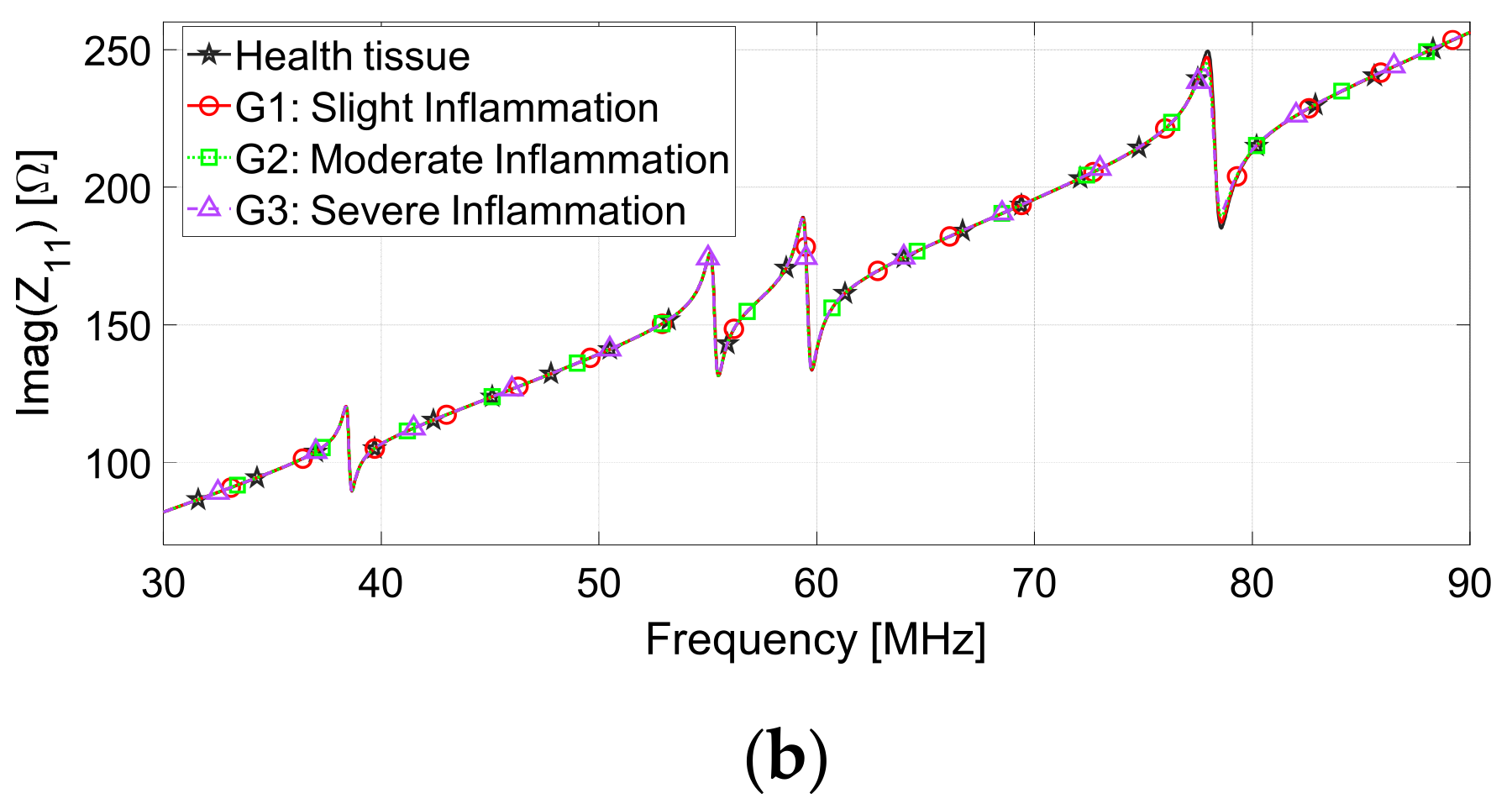
As described in Section 2.4, the numerical phantom was divided into four spatial sub-regions. One region expresses the dielectric properties of pathological tissue, while the others are representative of healthy tissue. According to the theoretical mechanism, by placing the probe loop close to the array conformally surrounding the biological phantom model, the input impedance readout should be noticeably changed only in correspondence to the resonant element near the inflamed region. This behavior allows for a clear distinction between the two tissue types, individuating the inflammation severity and also mapping the lesion spatial distribution. To validate this system ability, we simulated the scenario illustrated in Figure 5. Since the array was conformally placed 2 mm away from the tissue, we reproduced a contactless procedure in which the array is incorporated inside the wound bandage. The fourth resonant element was placed upon the inflamed sub-region, characterized by increasing severity (from G1 to G3), whereas the first, second and third unit cells were above the healthy ones. In Figure 13a,b, we reported the real and imaginary parts of the probe loop input impedance in this loaded and conformal configuration. Due to the deformation induced on the resonators to the biological model geometry adaptation, the resonance frequency of the unit cells blue shifted, which is consistent with the resulting change in inductance and capacity [51]. Through the inspection of the graphs, we can confirm that the proposed sensing methodology is efficient for detecting the inflamed region and permits the spatial localization of the disorder. Indeed, the increasing inflammation severity simulated in the fourth region resulted in a progressive amplitude decrease strictly around the SR4 unit cell resonance peak (mainly appreciable in the real part of the input impedance, close to 78 MHz), which is compatible with a corresponding enhancement in the tissue permittivity and conductivity. Conversely, the impedance behavior remains almost unchanged in the proximity of the other resonance peaks, demonstrating that the presence of the inflamed region has no influence on the other unit cells. The negligible variation in the resonance frequencies for the different implemented scenarios plays an important role in preventing overlapping, thus facilitating the potential expansion of the investigation area through the incorporation of additional spiral resonators into the array design.
Figure 14 summarizes the percentage variations in the maximum amplitude of the probe loop input impedance real component for each of the four peaks associated with the four SRs (from SR1 to SR4), relative to the three investigated inflammatory states. Specifically, by adopting the peak input impedance value corresponding to each SR in the presence of healthy tissue in the four sub-regions as the baseline, the percentage values were determined for the different inflammation degrees. The most significant percentages are associated with the fourth peak, whereas the other SRs exhibit significantly lower variations. Specifically, due to its greater distance from the inflamed area, the second unit cell presents negligible variations in its resonance, as expected. Therefore, the numerical results prove the validity of the proposed approach: the frequency-coded spiral resonator array demonstrates both excellent sensitivity and adequate spatial resolution, also allowing spatial localization of the tissue physiological status.

3.2. Experimental Characterization

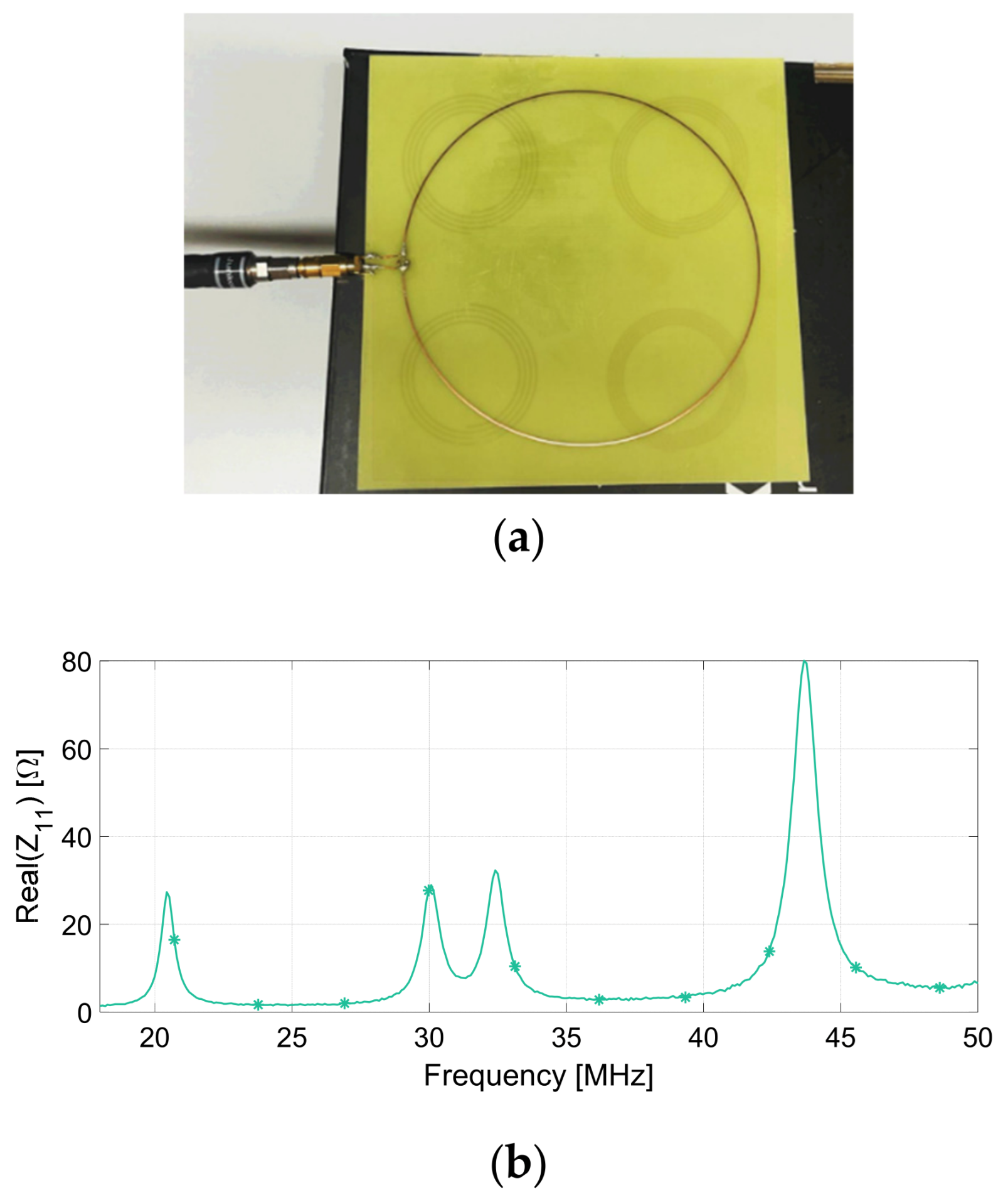
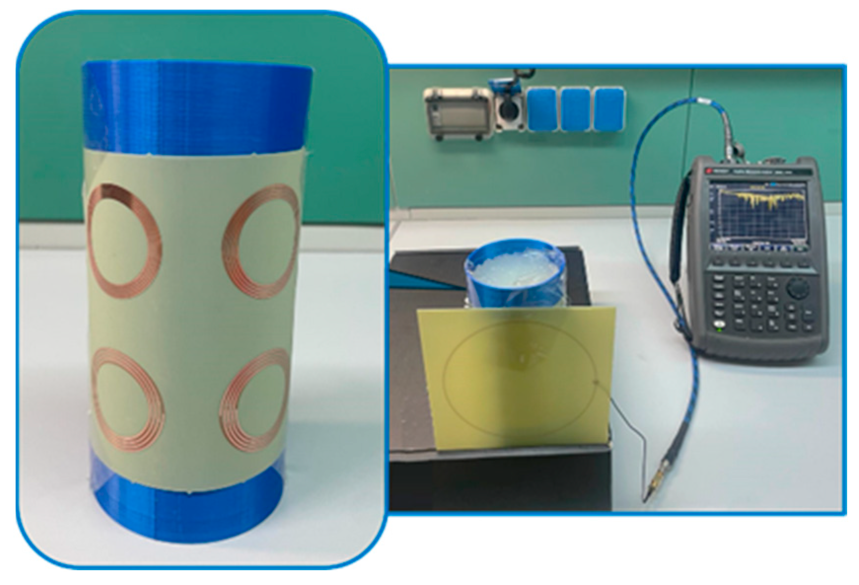
We carried out experimental measurements replicating the numerical approach. Therefore, as depicted in Figure 15a, the first set-up was meant to validate the frequency-coded spiral resonator array behavior in the planar configuration without biological phantoms. The input impedance measurements were performed by positioning the probe loop 5 mm above the array. As can be observed in Figure 15b, the experimental curve confirms the presence of the four peaks associated with the array unit cells and their resonant frequencies are in good agreement with the numerical results (reported in Figure 12). Table 7 provides a summary of the resonance frequencies obtained from both numerical and experimental methods. The existing discrepancies are mainly attributable to the mutual inductance coefficients between the probe loop and the unit cells, unavoidably different due to their relative positioning, and to the uncertainties on the commercial substrates’ effective dielectric properties. Then, the experimental measurements were devoted to the validation of the sensing system performance in the presence of cylindrical phantom models different for the degree of inflammation in the fourth quadrant region. As in numerical simulations, the frequency-coded array was wrapped around the cylindrical biological phantom (Figure 16).
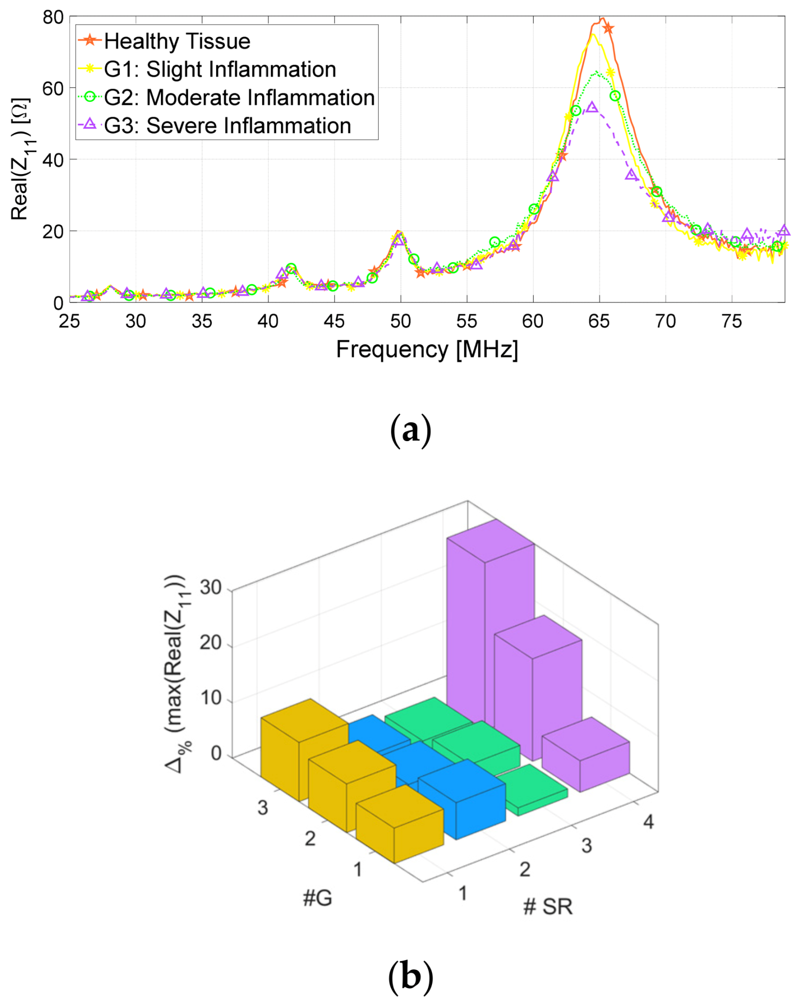
The external probe loop, employed both for the excitation of the passive array and for the output signal reading, was fixed in front of them, close to the cylindrical phantom wall, and connected to the VNA. Table 8 presents a comparison of the resonance frequencies obtained from both numerical and experimental analyses conducted involving healthy tissue and the array wrapped around the cylindrical phantom. Conversely, Figure 17a reports the measured real part of the probe loop input impedance for the different inflammation degrees, showing a satisfying agreement with the simulation. Indeed, the results highlight a progressive reduction in the maximum peak value of the probe loop input impedance real part in correspondence of the fourth SR (around 65 MHz) when phantoms replicating inflammatory states with increasing severity are analyzed. Instead, the amplitude of the other resonance peaks remains approximately constant, as desired. Finally, Figure 17b presents the percentage variations in the maximum amplitude peaks for each SR experimentally observed from the probe loop input impedance real part. The comparison is conducted by evaluating the three investigated inflammatory states against the baseline (healthy tissue). Therefore, in agreement with the numerical findings, the experimental results also show lower variations in the amplitudes’ peak of the first three SRs, whereas the fourth peak exhibits the most significant percentage variations. To conclude, the satisfying spatial resolution and sensitivity of the proposed frequency-coded solution were also proven experimentally.

4. Discussion

In this study, we presented the design and development of a wearable sensing system for monitoring the physiological status of biological tissues based on a contactless, passive, frequency-coded electromagnetic spiral resonator array. In particular, the array is conceived with a double-layer configuration, able to combine high sensitivity and spatial resolution. To the best of our knowledge, this is the first time that a similar solution has been proposed for health monitoring applications. We first explained the physical principles underlying the sensing approach. The passive array can be wrapped around any anatomical district, and it can be interrogated through an actively fed single-loop probe, inductively coupled with the unit cells. The self-resonance properties of the unit cells make them extremely sensitive to the changes in the dielectric properties of the tissues. In turn, the tissue’s physiological status correlates with the corresponding dielectric properties. To obtain the spatial localization, the proposed array has been frequency-coded; i.e., each unit cell has a slightly different resonant frequency. By simultaneously interrogating all the resonators, information about the tissue health and the spatial location of the lesion can be inferred. After that, we implemented a numerical test case reproducing a realistic application scenario for the proposed RF wearable sensing system. Subsequently, stratified phantoms were manufactured, mimicking both the skin layer and the muscle region, replicating healthy tissue and three progressive degrees of inflammation. Finally, the sensing system was fabricated by exploiting PCB technology. The experimental findings were in satisfying agreement with the numerical results, proving the validity of the proposed sensing technology.
To conclude, the proposed frequency-coded spiral resonator array can be extremely helpful in all the biomedical applications where a high-sensitivity and -spatial-resolution sensing system is required to infer tissue health status in a contactless way. Moreover, the possibility to integrate this passive device into smart bandages and garments makes it an appealing solution for increasing patient comfort and monitoring effectiveness. Future work will focus on enhancing the miniaturization of the array’s unit cells to achieve higher spatial resolution while maintaining sensitivity, thereby paving the way for real-world applications.

Author Contributions

A.M. (Angelica Masi), E.C. and S.R. were the main contributors to this work and were responsible for developing and implementing the methods, conducting measurements, and analysis; D.B. was responsible for investigation, supervision and writing; D.B. and A.M. (Agostino Monorchio) critically analyzed the results, suggested modifications and reviewed the manuscript. All authors have read and agreed to the published version of the manuscript.

Funding

This research received no external funding.

Data Availability Statement

The raw data supporting the conclusions of this article will be made available by the authors on request.

Acknowledgments

Work partially supported by the Italian Ministry of Research (MUR) in the framework of the FoReLab and CrossLab projects (Departments of Excellence).

Conflicts of Interest

Author Eliana Canicattì was employed by the company Free Space s.r.l. The remaining authors declare that the research was conducted in the absence of any commercial or financial relationships that could be construed as a potential conflict of interest.

Abbreviations

The following abbreviations are used in this manuscript:
CADComputer-Aided Design
PCBPrinted Circuit Board
PLAPoly-Lactic Acid
RFRadiofrequency
SMASub-Miniature version A
SRSpiral Resonator
VNAVector Network Analyzer

References

  1. Gao, W.; Ota, H.; Kiriya, D.; Takei, K.; Javey, A. Flexible Electronics toward Wearable Sensing. Acc. Chem. Res. 2019, 52, 523–533. [Google Scholar] [CrossRef] [PubMed]
  2. Nasiri, S.; Khosravani, M.R. Progress and challenges in fabrication of wearable sensors for health monitoring. Sens. Actuators A Phys. 2020, 312, 112105. [Google Scholar] [CrossRef]
  3. Sim, I. Mobile Devices and Health. N. Engl. J. Med. 2019, 381, 956–968. [Google Scholar] [CrossRef] [PubMed]
  4. Nguyen, K.D.; Chen, I.-M.; Luo, Z.; Yeo, S.H.; Duh, H.B.-L. A Wearable Sensing System for Tracking and Monitoring of Functional Arm Movement. IEEE/ASME Trans. Mechatron. 2010, 16, 213–220. [Google Scholar] [CrossRef]
  5. Kassal, P.; Zubak, M.; Scheipl, G.; Mohr, G.J.; Steinberg, M.D.; Steinberg, I.M. Smart bandage with wireless connectivity for optical monitoring of pH. Sens. Actuators B Chem. 2017, 246, 455–460. [Google Scholar] [CrossRef]
  6. Mostafalu, P.; Lenk, W.; Dokmeci, M.R.; Ziaie, B.; Khademhosseini, A.; Sonkusale, S.R. Wireless Flexible Smart Bandage for Continuous Monitoring of Wound Oxygenation. IEEE Trans. Biomed. Circuits Syst. 2015, 9, 670–677. [Google Scholar] [CrossRef]
  7. Ding, X.-R.; Clifton, D.; Ji, N.; Lovell, N.H.; Bonato, P.; Chen, W.; Yu, X.; Xue, Z.; Xiang, T.; Long, X.; et al. Wearable Sensing and Telehealth Technology with Potential Applications in the Coronavirus Pandemic. IEEE Rev. Biomed. Eng. 2020, 14, 48–70. [Google Scholar] [CrossRef]
  8. Devi, P.D.; Ilakiya, S. A Secure Employee Health Management System Using Werable Technology. In Proceedings of the 2021 International Conference on System, Computation, Automation and Networking (ICSCAN), Puducherry, India, 30–31 July 2021; IEEE: Piscataway, NJ, USA, 2021; pp. 1–5. [Google Scholar] [CrossRef]
  9. Pal, A.; Goswami, D.; Cuellar, H.E.; Castro, B.; Kuang, S.; Martinez, R.V. Early detection and monitoring of chronic wounds using low-cost, omniphobic paper-based smart bandages. Biosens. Bioelectron. 2018, 117, 696–705. [Google Scholar] [CrossRef]
  10. Derakhshandeh, H.; Kashaf, S.S.; Aghabaglou, F.; Ghanavati, I.O.; Tamayol, A. Smart Bandages: The Future of Wound Care. Trends Biotechnol. 2018, 36, 1259–1274. [Google Scholar] [CrossRef] [PubMed]
  11. Mondal, S.; Zehra, N.; Choudhury, A.; Iyer, P.K. Wearable Sensing Devices for Point of Care Diagnostics. ACS Appl. Bio Mater. 2020, 4, 47–70. [Google Scholar] [CrossRef] [PubMed]
  12. Khan, S.; Ali, S.; Bermak, A. Recent Developments in Printing Flexible and Wearable Sensing Electronics for Healthcare Applications. Sensors 2019, 19, 1230. [Google Scholar] [CrossRef] [PubMed]
  13. Farooqui, M.F.; Shamim, A. Low Cost Inkjet Printed Smart Bandage for Wireless Monitoring of Chronic Wounds. Sci. Rep. 2016, 6, 28949. [Google Scholar] [CrossRef] [PubMed]
  14. Honda, W.; Harada, S.; Arie, T.; Akita, S.; Takei, K. Wearable, Human-Interactive, Health-Monitoring, Wireless Devices Fabricated by Macroscale Printing Techniques. Adv. Funct. Mater. 2014, 24, 3299–3304. [Google Scholar] [CrossRef]
  15. Kassal, P.; Kim, J.; Kumar, R.; de Araujo, W.R.; Steinberg, I.M.; Steinberg, M.D.; Wang, J. Smart bandage with wireless connectivity for uric acid biosensing as an indicator of wound status. Electrochem. Commun. 2015, 56, 6–10. [Google Scholar] [CrossRef]
  16. Rahimi, R.; Brener, U.; Chittiboyina, S.; Soleimani, T.; Detwiler, D.A.; Lelièvre, S.A.; Ziaie, B. Laser-enabled fabrication of flexible and transparent pH sensor with near-field communication for in-situ monitoring of wound infection. Sens. Actuators B Chem. 2018, 267, 198–207. [Google Scholar] [CrossRef]
  17. Wang, Y.; Zhao, C.; Wang, J.; Luo, X.; Xie, L.; Zhan, S.; Kim, J.; Wang, X.; Liu, X.; Ying, Y. Wearable plasmonic-metasurface sensor for noninvasive and universal molecular fingerprint detection on biointerfaces. Sci. Adv. 2021, 7, eabe4553. [Google Scholar] [CrossRef]
  18. Ghaffari, R.; Yang, D.S.; Kim, J.; Mansour, A.; Wright, J.A.; Model, J.B.; Wright, D.E.; Rogers, J.A.; Ray, T.R. State of Sweat: Emerging Wearable Systems for Real-Time, Noninvasive Sweat Sensing and Analytics. ACS Sens. 2021, 6, 2787–2801. [Google Scholar] [CrossRef]
  19. Escobedo, P.; Bhattacharjee, M.; Nikbakhtnasrabadi, F.; Dahiya, R. Smart Bandage with Wireless Strain and Temperature Sensors and Batteryless NFC Tag. IEEE Internet Things J. 2020, 8, 5093–5100. [Google Scholar] [CrossRef]
  20. Bukhari, S.S.; Vardaxoglou, J.Y.; Whittow, W. A Metasurfaces Review: Definitions and Applications. Appl. Sci. 2019, 9, 2727. [Google Scholar] [CrossRef]
  21. Zhang, S.; Wong, C.L.; Zeng, S.; Bi, R.; Tai, K.; Dholakia, K.; Olivo, M. Metasurfaces for biomedical applications: Imaging and sensing from a nanophotonics perspective. Nanophotonics 2020, 10, 259–293. [Google Scholar] [CrossRef]
  22. Alsaedi, D.; El Badawe, M.; Ramahi, O.M. A Metasurface for Biomedical Imaging Applications. In Proceedings of the 2021 IEEE International Symposium on Antennas and Propagation and USNC-URSI Radio Science Meeting (APS/URSI), Singapore, 4–10 December 2021; IEEE: Piscataway, NJ, USA, 2021; pp. 589–590. [Google Scholar]
  23. Jiang, S.; Liu, X.; Liu, J.; Ye, D.; Duan, Y.; Li, K.; Yin, Z.; Huang, Y. Flexible Metamaterial Electronics. Adv. Mater. 2022, 34, e2200070. [Google Scholar] [CrossRef]
  24. Huang, X.; Guo, W.; Liu, S.; Li, Y.; Qiu, Y.; Fang, H.; Yang, G.; Zhu, K.; Yin, Z.; Li, Z.; et al. Flexible Mechanical Metamaterials Enabled Electronic Skin for Real-Time Detection of Unstable Grasping in Robotic Manipulation. Adv. Funct. Mater. 2022, 32, 2109109. [Google Scholar] [CrossRef]
  25. Brizi, D.; Conte, M.; Monorchio, A. A Performance-Enhanced Antenna for Microwave Biomedical Applications by Using Metasurfaces. IEEE Trans. Antennas Propag. 2023, 71, 3314–3323. [Google Scholar] [CrossRef]
  26. Rotundo, S.; Brizi, D.; Flori, A.; Giovannetti, G.; Menichetti, L.; Monorchio, A. Shaping and Focusing Magnetic Field in the Human Body: State-of-the Art and Promising Technologies. Sensors 2022, 22, 5132. [Google Scholar] [CrossRef] [PubMed]
  27. Gong, J.; Seyed, T.; Davis, J.U.; Yang, X.-D. Indutivo: Contact-Based, Object-Driven Interactions with Inductive Sensing. In Proceedings of the 31st Annual ACM Symposium on User Interface Software and Technology, Berlin, Germany, 14 October 2018; ACM: New York, NY, USA, 2018; pp. 321–333. [Google Scholar]
  28. Hsieh, M.-J.; Guo, J.-L.; Lu, C.-Y.; Hsieh, H.-W.; Liang, R.-H.; Chen, B.-Y. RFTouchPads: Batteryless and Wireless Modular Touch Sensor Pads Based on RFID. In Proceedings of the 32nd Annual ACM Symposium on User Interface Software and Technology, New Orleans, LA, USA, 17 October 2019; ACM: New York, NY, USA, 2019; pp. 999–1011. [Google Scholar]
  29. Li, Z.; Tian, X.; Qiu, C.-W.; Ho, J.S. Metasurfaces for bioelectronics and healthcare. Nat. Electron. 2021, 4, 382–391. [Google Scholar] [CrossRef]
  30. Brizi, D.; Stang, J.P.; Monorchio, A.; Lazzi, G. On the design of planar arrays of nonresonant coils for tunable wireless power transfer applications. IEEE Trans. Microw. Theory Tech. 2020, 68, 3814–3822. [Google Scholar] [CrossRef]
  31. Brizi, D.; Fontana, N.; Costa, F.; Tiberi, G.; Galante, A.; Alecci, M.; Monorchio, A. Design of Distributed Spiral Resonators for the Decoupling of MRI Double-Tuned RF Coils. IEEE Trans. Biomed. Eng. 2020, 67, 2806–2816. [Google Scholar] [CrossRef]
  32. Lu, D.; Yan, Y.; Avila, R.; Kandela, I.; Stepien, I.; Seo, M.; Bai, W.; Yang, Q.; Li, C.; Haney, C.R.; et al. Bioresorbable, Wireless, Passive Sensors as Temporary Implants for Monitoring Regional Body Temperature. Adv. Healthc. Mater. 2020, 9, 2000942. [Google Scholar] [CrossRef]
  33. Lu, D.; Yan, Y.; Deng, Y.; Yang, Q.; Zhao, J.; Seo, M.; Bai, W.; MacEwan, M.R.; Huang, Y.; Ray, W.Z.; et al. Bioresorbable Wireless Sensors as Temporary Implants for In Vivo Measurements of Pressure. Adv. Funct. Mater. 2020, 30, 202003754. [Google Scholar] [CrossRef]
  34. Li, S.; Lu, D.; Li, S.; Liu, J.; Xu, Y.; Yan, Y.; Rodriguez, J.Z.; Bai, H.; Avila, R.; Kang, S.; et al. Bioresorbable, wireless, passive sensors for continuous pH measurements and early detection of gastric leakage. Sci. Adv. 2024, 10, eadj0268. [Google Scholar] [CrossRef]
  35. Arai, T.; Hirayama, H. Folded Spiral Resonator with Double-Layered Structure for Near-Field Wireless Power Transfer. Energies 2020, 13, 1581. [Google Scholar] [CrossRef]
  36. Wang, X.; Pang, J.; Tan, Q.; Dong, H.; Zhao, N.; Xue, T. Design of double-layer parallel printed spiral coil for wireless power transfer applied to rotating equipment. Sens. Actuators A Phys. 2021, 331, 112761. [Google Scholar] [CrossRef]
  37. Masi, A.; Brizi, D.; Monorchio, A. Millimetric Inclusion Detection Through a Contactless Microwave Spiral Sensor for Biomedical Applications. IEEE Sens. J. 2023, 23, 12796–12807. [Google Scholar] [CrossRef]
  38. Mohammed, B.J.; Manoufali, M.; Naqvi, S.A.R.; Bialkowski, K.S.; Mills, P.C.; Abbosh, A.M. Using Dielectric Properties of Solid Fraction and Water Content to Characterize Tissues at Different Health and Age Conditions. IEEE J. Electromagn. RF Microwaves Med. Biol. 2019, 4, 69–77. [Google Scholar] [CrossRef]
  39. Gabriel, S.; Lau, R.W.; Gabriel, C. The dielectric properties of biological tissues: III. Parametric models for the dielectric spectrum of tissues. Phys. Med. Biol. 1996, 41, 2271–2293. [Google Scholar] [CrossRef]
  40. Brizi, D.; Fontana, N.; Costa, F.; Monorchio, A. Accurate Extraction of Equivalent Circuit Parameters of Spiral Resonators for the Design of Metamaterials. IEEE Trans. Microw. Theory Tech. 2018, 67, 626–633. [Google Scholar] [CrossRef]
  41. Gabriel, C.; Bentall, R.H.; Grant, E.H. Comparison of the dielectric properties of normal and wounded human skin material. Bioelectromagnetics 1987, 8, 23–27. [Google Scholar] [CrossRef] [PubMed]
  42. Available online: https://www.keysight.com/it/en/product/N9918A/fieldfox-a-handheld-microwave-analyzer-26-5-ghz.html (accessed on 10 June 2025).
  43. Ito, K.; Furuya, K.; Okano, Y.; Hamada, L. Development and characteristics of a biological tissue-equivalent phantom for microwaves. Electron. Commun. Jpn. Part I Commun. 2000, 84, 67–77. [Google Scholar] [CrossRef]
  44. Yu, Y.; Lowe, A.; Anand, G.; Kalra, A. Tissue phantom to mimic the dielectric properties of human muscle within 20 Hz and 100 kHz for biopotential sensing ap-plications. In Proceedings of the 2019 41st Annual International Conference of the IEEE Engineering in Medicine and Biology Society (EMBC), Berlin, Germany, 23–27 July 2019; IEEE: Piscataway, NJ, USA, 2019; pp. 6490–6493. [Google Scholar] [CrossRef]
  45. Dąbrowska, A.K.; Rotaru, G.-M.; Derler, S.; Spano, F.; Camenzind, M.; Annaheim, S.; Stämpfli, R.; Schmid, M.; Rossi, R.M. Materials used to simulate physical properties of human skin. Ski. Res. Technol. 2016, 22, 3–14. [Google Scholar] [CrossRef]
  46. Van Nunen, T.; Huismans, E.; Mestrom, R.; Bentum, M.; Visser, H. DIY Electromagnetic Phantoms for Biomedical Wireless Power Transfer Experiments. In Proceedings of the 2019 IEEE Wireless Power Transfer Conference (WPTC), London, UK, 18–21 June 2019; IEEE: Piscataway, NJ, USA, 2019; pp. 399–404. [Google Scholar] [CrossRef]
  47. Aminzadeh, R.; Saviz, M.; Shishegar, A. Theoretical and experimental broadband tissue-equivalent phantoms at microwave and millimetre-wave frequencies. Electron. Lett. 2014, 50, 618–620. [Google Scholar] [CrossRef]
  48. Ianniello, C.; de Zwart, J.A.; Duan, Q.; Deniz, C.M.; Alon, L.; Lee, J.; Lattanzi, R.; Brown, R. Synthesized tissue-equivalent dielectric phantoms using salt and polyvinylpyrrolidone solutions. Magn. Reson. Med. 2017, 80, 413–419. [Google Scholar] [CrossRef] [PubMed]
  49. Duan, Q.; Duyn, J.H.; Gudino, N.; de Zwart, J.A.; van Gelderen, P.; Sodickson, D.K.; Brown, R. Characterization of a dielectric phantom for high-field magnetic resonance imaging applications. Med. Phys. 2014, 41, 102303. [Google Scholar] [CrossRef] [PubMed]
  50. Alwaleedy, S.; Mohemmed, S.; Karale, R.; Kumbharkhane, A.C.; Roy, B.R.; Sarode, A.V. Study of Dielectric and Thermodynamic properties of Aqueous Glycine. Review 2022. [Google Scholar] [CrossRef]
  51. Lu, Y.; Yang, W.; Wang, Y.; Fan, Q.; Duan, X.; Xie, M. Spiral Resonator-based Corneal Contact Lens For Intraocular Pressure Monitoring. In Proceedings of the 2022 28th International Conference on Mechatronics and Machine Vision in Practice (M2VIP), Nanjing, China, 16–18 November 2022; IEEE: Piscataway, NJ, USA, 2022; pp. 1–6. [Google Scholar] [CrossRef]
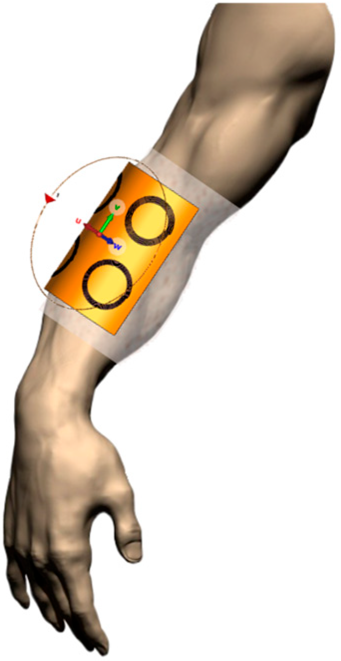
Figure 1. Schematic representation of the proposed concept: a passive and wearable spiral resonator array is interrogated by an external device.
Applsci 15 09015 g001
Figure 2. Equivalent lumped circuit for a single spiral resonator unit cell inductively coupled with the external probe loop.
Applsci 15 09015 g002
Figure 3. (a) CAD model of the external single-loop probe. (b) CAD model of the entire spiral resonator array, highlighting both the top and bottom layers.
Applsci 15 09015 g003
Figure 4. CAD model of the proposed 2 × 2 spiral resonator array and the external probe, placed beneath it. (a) Planar configuration. (b) Conformal configuration.
Applsci 15 09015 g004
Figure 5. CAD model of the conformal sensing system including the layered phantom (external skin and inner muscle). The phantom is divided into four sub-regions, in correspondence with the four unit-cells. (a) Healthy tissue condition for the entire phantom model. (b) Presence of the inflammatory state in the fourth sub-region (dark red), characterized by the dielectric properties of pathological tissues.
Applsci 15 09015 g005
Figure 6. (a) Top view of the probe loop prototype: it consists of a 0.8 mm thick FR-4 dielectric substrate with a standard 35 µm thick copper microstrip. (b) Top and bottom view of the frequency-coded array prototype. It consists of a flexible (127 µm thick) ISOLA dielectric substrate with a double-layer standard 35 µm thick copper microstrip.
Applsci 15 09015 g006
Figure 7. 3D-shaped supporting structures for the four phantom models. (a) 3D-printing process. (b) Assembly of the outer and interior cylinders to form the double-layered (skin and muscle) healthy phantom. (c) Thick base located at the bottom of the outer cylinder, including a runner for easy and stable insertion of the inner cylinder. (d) Assembly of the outer and interior cylinders to form the double-layered (skin and muscle) pathological phantom (G1 to G3 cases). The central wall was specifically constructed to restrict the passage of fluid, confining the inflamed area to just one-fourth of the overall internal volume.
Applsci 15 09015 g007aApplsci 15 09015 g007b
Figure 8. Experimental set-up of the measurement campaign for the characterization of water-based solutions.
Applsci 15 09015 g008
Figure 9. Dielectric properties of the gelatinous-based phantoms. Real part of permittivity (a) and conductivity (b) for water-based solutions with the addition of increasing glycine concentrations. As can be observed, the real part of the relative permittivity increases proportionally with the molar concentration of C2H5NO2. Real part of permittivity (c) and conductivity (d) for water-based solutions with the addition of increasing salt concentrations. In this case, conductivity increases proportionally with the molar concentration of NaCl.
Applsci 15 09015 g009aApplsci 15 09015 g009b
Figure 10. (a) Quadratic relationship between permittivity and glycine (molarity) concentration, based on data extracted at 100 MHz. (b) Quadratic relationship between conductivity and NaCl (molarity) concentration, based on data extracted at 100 MHz.
Applsci 15 09015 g010
Figure 11. Flow chart (from left to right) of agar-based phantom fabrication for mimicking an inflammatory state. (1) The first phase consists of filling the internal structure, first pouring and cooling the inflammation-like fluid in a quarter of the inner cylinder (one of the two halves below), then filling and cooling the other three portions with healthy-like fluid. (2) Inner-cylinder extraction. (3) Skin-like liquid phase injection by syringe. (4) Result after the final long cooling.
Applsci 15 09015 g011
Figure 12. Input impedance of the probe loop when the spiral resonator array is simulated in a planar configuration and without biological load: (a) real and (b) imaginary component.
Applsci 15 09015 g012aApplsci 15 09015 g012b
Figure 13. Numerical input impedance of the probe loop when the spiral resonator array is simulated and wrapped around the cylindrical biological phantom. (a) Input impedance real and (b) imaginary components. As better highlighted in Figure 14, the array unit cell placed close to the inflamed tissue (operating around 78 MHz) exhibits a variation in the resonance peak amplitude directly proportional to the level of inflammation.
Applsci 15 09015 g013aApplsci 15 09015 g013b
Figure 14. Percentage variations in the maximum amplitude of the numerical probing loop’s input impedance, calculated by comparing the different cases of inflamed tissue (from G1 to G3) with respect to the baseline (healthy tissue), respectively, for each of the four SR peaks.
Applsci 15 09015 g014
Figure 15. (a) Set-up for the probe loop input impedance experimental measurement when the spiral resonator array is in planar configuration without biological load. (b) Real part of the probe loop input impedance measured with the array in planar configuration and in the absence of biological load.
Applsci 15 09015 g015
Figure 16. Experimental set-up including the VNA, the probe loop placed in front of the double-stratified agar-based phantom representing the human forearm, around which the frequency-coded spiral resonator array is wrapped. Magnification of the array arrangement is shown as an inset.
Applsci 15 09015 g016
Figure 17. (a) Real part of the probe loop input impedance measured in the presence of a conformal spiral resonator array wrapped around the biological load. The fourth quadrant region of the phantom is progressively characterized by the dielectric properties of healthy, slightly inflamed (G1), moderately inflamed (G2) and severely inflamed (G3) tissue. The other three regions are composed of healthy tissues. (b) Percentage variations in the maximum amplitude of the experimental probing loop’s input impedance real component, calculated by comparing the different cases of inflamed tissue (from G1 to G3) with respect to the baseline (healthy tissue), respectively, for each of the four SR resonance peaks.
Applsci 15 09015 g017
Table 1. Active probe loop and spiral resonator geometry and materials.
ParameterProbe LoopSR1SR2SR3SR4
External radius65 mm20 mm20 mm20 mm20 mm
Microstrip width wstrip0.700 mm0.700 mm0.700 mm0.700 mm0.700 mm
Microstrip thickness hstrip35 µm35 µm35 µm35 µm35 µm
Pitch-1 mm1.25 mm1.54 mm1.61 mm
Number of turns15443.5
Conductive materialCopperCopperCopperCopperCopper
Substrate materialFR-4 (εr = 4.3, tanδ = 0.02)ISOLA (εr = 3.45, tanδ = 0.0015)ISOLA (εr = 3.45, tanδ = 0.0015)ISOLA (εr = 3.45, tanδ = 0.0015)ISOLA (εr = 3.45, tanδ = 0.0015)
Substrate area 136 × 136 mm260 × 60 mm2 60 × 60 mm2 60 × 60 mm2 60 × 60 mm2
Substrate thickness 0.8 mm0.127 mm0.127 mm0.127 mm0.127 mm
Table 2. Resonant frequency of the stand-alone array unit cells in planar and conformal configurations.
# SRResonance Frequency (MHz), PlanarResonance Frequency (MHz), Conformal
I30.149.2
II42.670.2
III46.375.8
IV60.297.0
Table 3. Dielectric properties of healthy tissues evaluated at the specific SR operating frequencies.
Operating Frequency (MHz)Skin
r, σ (S/m))
Muscle
r, σ (S/m))
49.2127.2, 0.3783.5, 0.67
70.2100.6, 0.4274.9, 0.68
75.895.6, 0.4373.3, 0.69
97.082.2, 0.4669.0, 0.70
Table 4. Dielectric properties of the adopted inflammatory states (fourth region), simulated by increasing permittivity and conductivity.
Inflammation SeveritySkin
r, σ (S/m))
Muscle
r, σ (S/m))
G1 (slight)94.5, 0.5379.3, 0.80
G2 (medium)108.7, 0.6191.2, 0.92
G3 (severe)125.0, 0.70104.9, 1.06
Table 5. Geometrical features of the adopted PLA supporting structure for phantom fabrication.
Geometrical FeaturesValue (mm)
Outer Cylinder Diameter83.6
Outer Cylinder Length170
Outer Cylinder Thickness1.8
Inner Cylinder Diameter77.8
Inner Cylinder Length175
Inner Cylinder Thickness1.2
Base thickness5.0
Runner Thickness1.8
Separation Layer Thickness1.2
Table 6. Matlab linear model Poly2 coefficients for the retrieved tissue dielectric properties’ relationships with additives.
Polynomial Coefficient Glycine Permittivity ModelSalt Permittivity Model
a−11.19−138
b41.22051.23
c87.87−1.5
Table 7. Unit cell resonant frequencies intercomparison: full-wave against experimental results for planar array configuration without phantom.
QuadrantResonance Frequency (MHz), Full-Wave Resonance Frequency (MHz), Measurement
I3022
II4230
III4633
IV6044
Table 8. Unit cell resonant frequencies intercomparison: full-wave against experimental results for conformal array configuration with healthy phantom.
QuadrantResonance Frequency (MHz), Full-Wave Resonance Frequency (MHz), Measurement
I3828
II5542
III5950
IV7865
Disclaimer/Publisher’s Note: The statements, opinions and data contained in all publications are solely those of the individual author(s) and contributor(s) and not of MDPI and/or the editor(s). MDPI and/or the editor(s) disclaim responsibility for any injury to people or property resulting from any ideas, methods, instructions or products referred to in the content.