Abstract
The shear strength parameters of landslide zones are the necessary data basis for landslide stability evaluation and landslide surge disaster chain research. It is important to determine the physical and mechanical parameters of landslide zones scientifically and reasonably. In this study, four small residual landslide deposits near the Hei Duo Village road in Diebu County, Gansu Province, were investigated. The research involved detailed field investigations, the construction of landslide engineering geological models, and the use of the transfer coefficient method for simultaneous/inverse inversion and sensitivity analysis of the strength parameters of the four landslides. Based on the inversion results, an analysis of the landslide formation mechanism was conducted. The inversion results yielded the shear strength parameters of the sliding surface soil as c = 30.12 kPa and φ = 21.08°. It was found that the excavation at the base of the slope is the direct triggering factor for the landslides, with the 3# landslide being the most affected by the base excavation. In terms of the type of movement, all four landslides belong to the retrogressive landslide, with the maximum shear strain increment mainly concentrated at the slope angle after excavation. The slope body experiences shear failure, which is in good agreement with the field conditions. The study provides reference for stability prediction and disaster prevention and control of reservoir bank slope.
1. Introduction
Landslide hazards are the most widely distributed and numerous type of geological disasters, causing significant casualties and property losses every year [1]. Therefore, accurately evaluating slope stability is of great practical significance, providing a scientific basis for disaster prevention and mitigation. The slide zone soil, as a critical component of landslides, controls the development and evolution process of landslides through its stress state and mechanical properties [2]. Hence, the shear strength parameters of slip zone soils are key to landslide hazard prediction and assessment [3].
Methods for determining the strength parameters of slip zone soils include the test method, parameter inversion method and engineering analogy method. When determining shear strength parameters through experiments or engineering analogy, the obtained values often exhibit significant dispersion due to limitations in test materials, conditions, and variations in geological environments across different slopes, making them unreliable for practical applications [4,5,6,7]. For slopes or landslides that have already experienced sliding or significant deformation, the inversion method can more accurately estimate the strength parameters of slip zone soils. For some engineering cases where it is difficult to obtain the original soil samples, inversion analysis is very effective and may be the only method for calculating the shear strength parameters. Zuo et al. [8] considered residual thrust of landslide mass to determine recommended shear strength parameters for slip surfaces with different material compositions in typical landslides; Bi et al. [9] used the transfer coefficient method and Monte Carlo method to obtain the strength parameters of slip zone soils in a reservoir landslide and conducted stability analysis; Chen Fangming et al. [10] conducted a stability analysis of a landslide in the Three Gorges Reservoir Area using the shear strength parameters of the soil obtained through the inversion method; Kang Qinrong et al. [11] conducted parameter inversion for a highway landslide using the limit equilibrium method; Wang Dong et al. [12] applied the residual thrust method for multi-parameter inversion of rock shear strength and validated the results experimentally; Jiang Wei et al. [13] proposed a reverse iterative correction inversion method for the shear strength of rock and soil masses. The obtained shear strength of rock and soil masses can be well matched with the stable state and deformation signs of slopes [14].
In conclusion, the parameter inversion analysis method is widely used in the reasonable selection of shear strength parameters of sliding zone soil. Sometimes, for some engineering cases where it is difficult to obtain undisturbed soil samples, back analysis may be a very effective and unique method for determining the shear strength parameters of sliding zone soil. In this paper, the transfer coefficient method in the limit equilibrium principle and the strength reduction method in numerical calculation are applied in the inversion of shear strength parameters of sliding zone soil.
This study focuses on four small landslides along the road in Heiduo Village, Diebu County, Gansu Province. The strength parameters of the sliding mass are obtained through the inversion method, and the deformation and instability mechanism of the landslide are then analyzed.
2. Engineering Geological Overview
The study area is located on the northern slope of Diebu County, Gansu Province (N 34°04′05″, E103°52′38″). The Middle Devonian stratum is taken as the target stratum in the study area. The lithology is shale interbedded with argillaceous siltstone, thin argillaceous limestone interbedded with shale, thick limestone, shale interbedded with limestone and sandstone lens, etc. The occurrence is 20°~40°∠60°~70°, with great change, serious deformation and distortion, and many strata being steep (Figure 1). Carbonaceous shale has a high degree of weathering and is prone to softening and argillization in water.
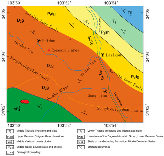
Figure 1.
Geological map of the study area.
3. Analysis of the Basic Characteristics and Causes of Landslides
Based on field investigations, local interviews, and historical image comparisons (Figure 2), it was found that the slope remained relatively stable before 2016 and the vegetation coverage was good with no signs of deformation. In 2016, local villagers conducted the first slope-cutting excavation for road construction on the southern (lower) side of the study area. However, this excavation did not directly pass through the four landslide areas studied in this paper, so the impact of this excavation on the study area was not obvious. In 2020, a second slope-cutting excavation for road construction was carried out. After this excavation, the slope had undergone local deformation, and the vegetation was damaged. Moreover, a large number of tensile transverse cracks appeared at the top of the slope, and several small-scale cracks developed on the slope body, but they were not completely destroyed. In November 2021, further road widening exacerbated slope deformation, leading to progressive extension and vertical displacement (downthrow) of the cracks, with a height difference of approximately 0.5–1 m between the two sides of the cracks. Additionally, soil extrusion was observed at the slope toe, accompanied by groundwater seepage. Ultimately, in June 2022, these four slope sections experienced destabilization and failure; with the passage of time, the landslide damage is more and more extensive, resulting in landslides (Figure 3).
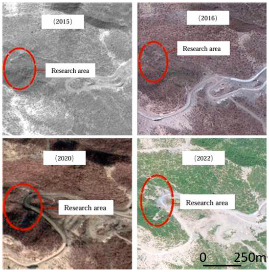
Figure 2.
Historical images of the study area.
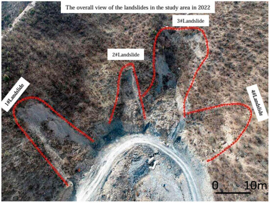
Figure 3.
Full view of the study area.
The four landslides (Table 1) share a common slip bed composed of shale from the Middle Devonian (D2g), while the sliding masses consist of Quaternary residual–deluvial gravelly soil and silty clay. Distinct geomorphic features are observed, including steep scarps and tensile cracks at the landslide crowns, as well as striations along the boundaries. The thickness of the sliding mass varies spatially, being greatest in the central portion and tapering toward both lateral margins. At the cutting outlet of the leading edge, a slip zone of a certain thickness with scratch marks can be seen.

Table 1.
Basic characteristics of landslides.
The slip zone occurs at the interface between Quaternary overburden and bedrock, exhibiting distinct striations (Figure 4). With a thickness of 5–15 cm, this zone consists of silty clay and finely pulverized shale particles, displaying a powdery texture. The material exhibits high moisture content and demonstrates strong interparticle cohesion.
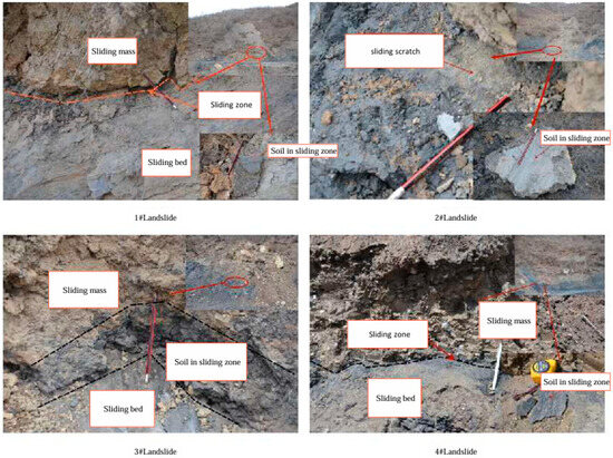
Figure 4.
Composition and distribution of slip soil.
All four landslides feature sliding masses composed of loose gravelly soil and Quaternary silty clay. The slide bed consists of severely fragmented and weathered shale, and this geological configuration creates favorable conditions for the development of retrogressive landslides. Within the landslide area, long-term vegetation restoration projects involving irrigation have significantly increased slope water content, softening the slip zone and consequently reducing slope stability. The village road passes through the foot of the slope at the front edge of four landslides. Coupled with the road widening and excavation towards the foot of the slope, an artificial open surface about 2 to 3 m high has been formed on the side facing the mountain. The excavation of the anti-sliding section generated favorable release conditions at the landslide fronts, producing significant stress concentration at the slope toes. This process substantially diminished the anti-sliding resistance, providing optimal conditions for the initiation of these four landslides. Therefore, these failures represent typical small-scale retrogressive landslides in residual–deluvial deposits.
4. Inversion Analysis of Shear Strength Parameters for Slip Zone Soils
4.1. Selection of the Inversion Calculation Section
Based on field investigations of surface deformation features, landslide morphological characteristics, height of the rear scarp, and thickness of the sliding mass at the toe shear outlet, combined with subsurface exploration data, the complete slip surface can be reliably reconstructed. It has the prerequisite conditions for the inversion of sliding surface parameters. Using the limit equilibrium method, the shear strength parameters (cohesion c and internal friction angle φ) of the landslide slip zone were determined. This method is widely used because it simplifies calculations and enables the estimation of the thrust force required for stabilization. According to GB50021-2001, when the safety factor is 1.0, the shear strength parameters (c, φ) are back-calculated using the transfer coefficient method (unbalanced thrust force method), as expressed by the following equation:
The analysis utilized current topographic data (Figure 5) supplemented with historical imagery to reconstruct the pre-failure terrain. Representative cross-sections were developed along each landslide’s primary movement direction. Based on profile geometry, slope gradients, overall morphology and identified slip surfaces, the longitudinal profiles of all four landslides were discretized into multiple calculation blocks (Figure 6).
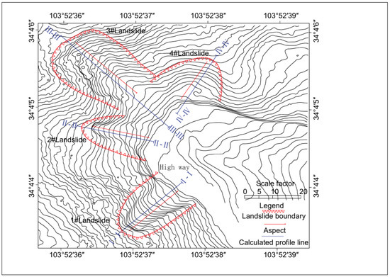
Figure 5.
Plan of the four landslides.
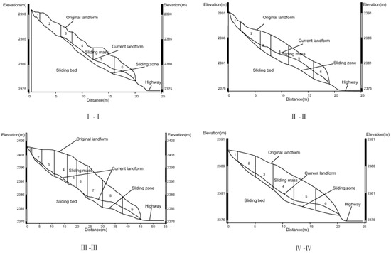
Figure 6.
Calculation profile of the four landslides.
4.2. Analysis of Inversion Results
The sliding masses of these four landslides consist of colluvial–deluvial gravelly soils and silty clays, and the average natural unit weight, which was tested in the laboratory, is 21.2 kN/m3. To solve for the two unknowns, cohesion (c) and internal friction angle (φ), two independent equations are required. Therefore, in the case of multiple landslides, a ‘pairwise combination’ of the equations from two landslides is used to solve for each (c, φ) pair. In this study, 4C2 = 4 × 3/2 = 6 sets of parameters were derived (Table 2).
Table 2.
Shear strength parameters of profiles.
To identify the optimal shear strength parameters, the unbalanced thrust transfer coefficient method was employed to calculate stability coefficients under different combinations of cohesion (c) and internal friction angle (φ) for all four landslides (Table 3). Additionally, the sensitivity of landslide stability to variations in c and φ values was quantified using Equation (1).
where represents the sensitivity influence factor;
Table 3.
Landslide stability coefficients for different combinations of c and φ values.
denotes the variation in output result Y (dependent on parameter X);
indicates the variation in parameter X;
corresponds to the variation in the factor of safety under different shear strength parameters;
represents the baseline value of FS (here taken as the mean of the six variable groups);
signifies the variation in shear strength parameters.
denotes the maximum variation in shear strength parameters.
It is assumed that FS = 1 during inversion calculation, and when |ΔF| > 0.2, it is no longer considered. Based on the calculated results, Figure 7 [15,16,17] presents a summary of the influence of strength parameters (cohesion c and internal friction angle φ) on the safety factor of the slope.
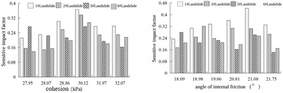
Figure 7.
Sensitivity analysis histograms.
The results indicate that the average sensitivity factors of strength parameters c and φ for the four landslides are 23.6% and 28%, respectively. Compared to cohesion (c), the internal friction angle (φ) has a more significant influence on landslide stability. This is because the internal friction angle is a parameter that describes the frictional resistance between particles within the material, reflecting the roughness of the geomaterial and the interactions between particles. An increase in the internal friction angle enhances the shear resistance of the landslide mass, thereby improving slope stability. Consequently, the internal friction angle has a greater impact on the stability coefficient of landslides, whereas the influence of cohesion is relatively smaller. As shown in Figure 7, when the shear strength parameters are c = 30.12 kPa and φ = 21.08°, they exhibit the highest sensitivity for the stability of the four landslides. Under this set of parameters, the corresponding stability coefficients of the four landslides show minimal dispersion, with a standard deviation of 0.0046.
5. Analysis of the Formation Mechanism of Landslides
5.1. Model Establishment and Parameter Selection
FLAC3D adopts the Mohr–Coulomb model, which is widely used to simulate the mechanical behavior of slip zone soils and most soil/rock masses in landslide studies. This model accurately captures the process of plastic deformation. The safety factor (FS) is determined using the strength reduction method (SRM). Initially, shear strength parameters are assigned, and then progressively reduced through iterative calculation until the slope reaches a critical state. The reduction factor at this point is defined as the safety factor. During model construction, computational efficiency and accuracy were balanced while minimizing boundary effects (Figure 8). The model’s bottom and lateral boundaries were constrained, while the top boundary remained free [18,19,20]. The 3D geological mesh was composed of tetrahedral and hexahedral elements.
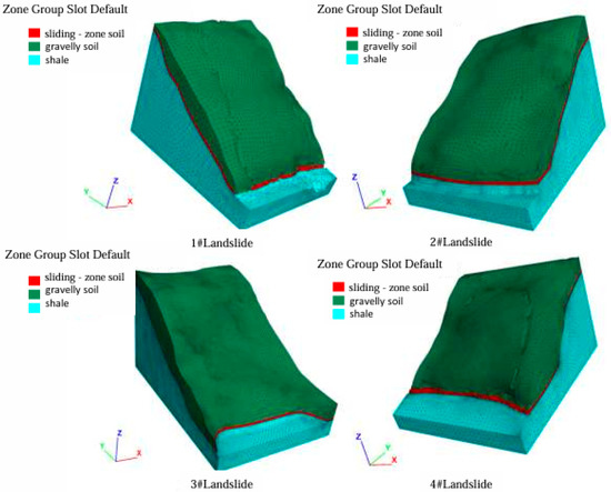
Figure 8.
Grid model.
The Mohr–Coulomb constitutive model was adopted for the simulations. The cohesion (c) and internal friction angle (φ) of the sliding zone soil were determined through inversion calculation(Table 4), while the parameters of other rock and soil layers were selected based on laboratory tests and prior research [21] (Table 5).
Table 4.
Detailed information about the landslide model.
Table 5.
Parameters of rock and soil.
5.2. Selection of Working Conditions
Three-dimensional simulations were conducted for the four landslides in the study area using the shear strength parameters from inversion calculation. Field investigations and local reports indicated that road widening involved approximately 2 m of slope toe excavation. Therefore, the deformation characteristics and stability of the four landslides were simulated under both natural conditions and slope toe excavation scenarios. For the excavation simulation, the initial displacement field induced by gravity was reset (i.e., initial geostatic equilibrium was achieved), ensuring that post-excavation displacements solely reflected the incremental changes caused by slope cutting [22,23,24].
To monitor deformation before and after excavation, observation points were placed along the main sliding profiles of the four landslides, covering both the slope surface and the toe (Figure 9). These points were used to quantify displacement variations at different locations of the landslide mass.
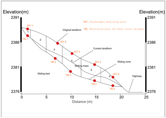
Figure 9.
Layout of monitoring points.
5.3. Analysis of Calculation Results
Based on the morphological characteristics of the landslides in the study area (Figure 3), the deformation mechanisms of the four landslides can be classified into two types.
Under self-weight loading, the overall displacement and shear deformation of the landslides primarily occurred in the front and middle sections. For Landslides #1, #2, and #4, significant displacement was observed at the front edge under gravitational forces. Among them, Landslide #2 exhibited the largest displacement (0.14 m), with the maximum deformation concentrated in the middle of the front edge. The slope gradient was steep, which is consistent with field observations (Figure 10). The maximum shear strain localized at the base of the front slope but did not propagate to the rear edge, where shear strain remained negligible. Therefore, these landslides were in a marginally stable to quasi-stable state.
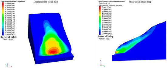
Figure 10.
Displacement and shear strain maps of landslide #2 under deadweight conditions.
Following excavation at the slope toe, the front-edge displacement of Landslides #1, #2, and #4 further increased, and the maximum displacement occurred in the middle of the front edge (the excavated zone). The middle and rear sections exhibited relatively minor displacement, while the underlying bedrock (shale) showed almost no movement. The front edge displayed uplift and sliding, and the maximum displacement of Landslide #4 was 1.7 m (Figure 11). The maximum shear strain concentrated at the base of the front slope and propagated backward, forming a continuous shear failure surface within the slope. Ultimately, the landslide was in an unstable state.
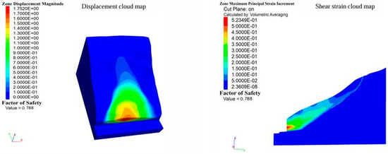
Figure 11.
Displacement and shear strain cloud map of landslide #2 after foot of slope excavation.
Before excavation, due to topographic constraints, the upper section of Landslide #3 was steep, while the lower section was gentler, creating a constricted anti-sliding segment in the middle. Maximum displacement occurred in the steeper upper section, but the slope remained relatively stable. After excavation, the loss of the front-edge anti-sliding segment led to a dramatic increase in displacement. The maximum displacement increased by 12 times, and significant displacement also occurred at the excavation site at the slope toe (Figure 12a). By comparing the shear strain cloud maps before and after the excavation of Landslide #3, the maximum shear strain of the slope before excavation occurred at the exit and middle section, which was not connected, and the deformation was relatively small. After excavation, the shear strain increased significantly, with the maximum increment of shear strain increasing by 15.7 times, and a through sliding surface was formed (Figure 12b). Due to the large volume of the sliding body, the anti-sliding effect in the middle was weakened, and the closure of the crack surface at the rear edge caused the accelerated failure of Landslide #3. The maximum reduction in its stability coefficient was 0.6 times that before excavation.
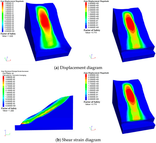
Figure 12.
Displacement and shear strain maps of landslide #3 before and after excavation.
Following slope toe excavation, the stability coefficients of all four landslides decreased significantly (Table 6). The maximum displacement and shear strain increments at monitoring points exhibited substantial increases due to excavation, with displacements amplifying by 11–12 times and shear strains by 7–16 times. Moreover, deformation was predominantly concentrated at the excavated slope toe (Figure 13). This suggests that for landslides with special anti-sliding segment, when the anti-slip mechanism disappears due to external disturbances.The resulting pull-effect accelerates landslide evolution, leading to more rapid and severe deformation. Therefore, in the analysis and engineering treatment of such landslides, it is imperative to thoroughly evaluate and mitigate the potential risks and impacts associated with retrogressive failure mechanisms.
Table 6.
Coefficients of stability of four landslides before and after excavation of the foot of the slope.
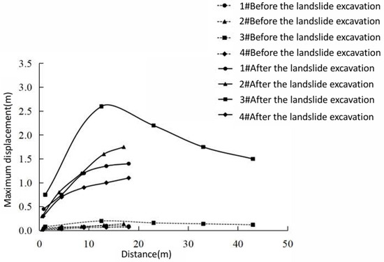
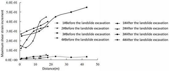
Figure 13.
Distribution of displacements and deformations at each monitoring point on the profile.
The four landslides are composed of loose gravelly soil and Quaternary silty clay, with their slip beds consisting of highly fractured and weathered shale. This geological configuration creates favorable conditions for slope failure, and toe excavation serves as the direct triggering factor. The excavation at the slope toe led to the absence of an anti-sliding section, triggering the redistribution of internal stresses within the slope mass. This process led to significant stress concentration at the slope toe, while simultaneously promoting the development of distinct shear strain localization zones in both the frontal and middle slope sections. As deformation progressed, these localized shear zones eventually interconnected, creating a continuous failure surface. These combined effects ultimately led to slope instability, which is a retrogressive characteristic of landslides.
6. Conclusions
- (1)
- Field geological investigations revealed that the lithological composition, topography, geomorphology, and geological structures in the study area provided the geological and material basis for landslide occurrence, and slope toe excavation serves as the triggering factor for landslide formation.
- (2)
- Inversion analysis of the four landslides in the study area determined the shear strength parameters of the sliding zone soil: c = 30.12 kPa, φ = 2 1.08°.
- (3)
- Simulation results of the four landslides demonstrated that slope toe excavation was the direct triggering factor for landslide occurrence. In terms of movement patterns, all four landslides exhibited retrogressive characteristics. The numerical simulation results are basically the same as the results after the landslide damage, which verifies the accuracy of the simulation.
- (4)
- For Landslide #3, featuring a constricted anti-sliding segment in its middle section, the disappearance of this stabilizing mechanism due to external disturbance significantly intensified the retrogressive effect, leading to more severe and rapid landslide development. Consequently, slope toe excavation exerted the most pronounced impact on Landslide #3.
- (5)
- Different rainfall intensities: with the increase in rainfall, the pore water pressure at the foot of the slope is greatly affected by rainwater infiltration, the displacement at the foot of the slope increases, and the plastic zone expands from the foot of the slope and tends to extend to the top of the slope, indicating that the soil at the foot of the slope is vulnerable to rainwater erosion, leading to a reduction in slope stability. However, the rainfall duration is short, the rainfall only infiltrates to a shallow depth, most of the soil in the deep layer of the slope is not affected by the rainfall depth, the pore water pressure and water content in the slope are less affected, and the transient saturation zone cannot be formed; moreover, the basic suction between most soil particles in the slope does not change much, the effective stress between soils can remain relatively stable, and the shear strength of the slope does not decrease significantly, so the slope is still in a stable state when the rainfall reaches the extreme rainfall intensity. However, drainage of the slope should also be conducted well on the basis of controlling the deformation of the accumulation body.
Author Contributions
Conceptualization and methodology, P.C. and Y.-Q.T.; software, P.C.; validation, P.C. and Y.-Q.T.; formal analysis, investigation and resources, Y.-Q.T.; data curation, writing—original draft preparation, writing—review and editing, P.C.; visualization, supervision, project administration, funding acquisition, G.-X.Y. All authors have read and agreed to the published version of the manuscript.
Funding
This research is supported by the Key Research and Development Program of Henan Province (Grant No. 221111321500). Sponsored by National Natural Science Foundation of China; the funding number: 42277141.
Institutional Review Board Statement
Not applicable.
Informed Consent Statement
Not applicable.
Data Availability Statement
Data will be made available on request.
Conflicts of Interest
Author Yong-Qiang Tang was employed by the company China Northwest Water Conservacy & Hydropower Engineering Consulting Co., Ltd. The remaining authors declare that the research was conducted in the absence of any commercial or financial relationships that could be construed as a potential conflict of interest.
References
- Froude, M.J.; Petley, D.N. Global fatal landslide occurrence from 2004 to 2016. Natureal Hazardas Earth Syst. Sci. 2018, 18, 2161–2181. [Google Scholar] [CrossRef]
- Chen, C.; Zhang, J. Research progress on determination methods of shear strength parameters of sliding zone soil. Chin. Foreign Highw. 2012, 32, 65–70. [Google Scholar]
- Li, Z.; Zhou, P. Research progress of coarse-grained slip zone soil in China. Nat. Hazards 2023, 118, 1–29. [Google Scholar] [CrossRef]
- Ren, Q.; Li, H. Back analysis of mechanical parameters of slope slip zone based on transfer coefficient method. People’s Pearl River 2019, 40, 21–26. [Google Scholar]
- Yang, R.; Huang, J.; Griffiths, D.V.; Li, J.; Sheng, D. Importance of soil property sampling location in slope stability assessment. Can. Geotech. J. 2019, 56, 335–346. [Google Scholar] [CrossRef]
- Behnia, M.; Nateghpour, B.; Tavakoli, J.; Broujerdi, M.S. Comparison of experimental and empirical methods for estimating the shear strength of rock joints based on the statistical approach. Environ. Earth Sci. 2020, 79, 361. [Google Scholar] [CrossRef]
- Zhang, S.; Zhang, K. Discussion on several problems in the calculation of landslide stability. Reconnaiss. Tech. Data 1975, 14, 5–13. [Google Scholar]
- Zuo, S.; Zhao, L.; Deng, D.; Han, Z.; Zhao, B.; Zhao, Z. Back analysis of shear strength parameters for progressive landslides: Case study of the Caifengyan landslide, China. Bull. Eng. Geol. Environ. 2022, 81, 19. [Google Scholar] [CrossRef]
- Bi, R.; Ehret, D.; Xiang, W.; Rohn, J.; Schleier, M.; Jiang, J. Landslide reliability analysis based on transfer coefficient method: A case study from Three Gorges Reservoir. J. Earth Sci. 2012, 23, 187–198. [Google Scholar] [CrossRef]
- Chen, F.; Wang, T.; Du, M. Landslide stability analysis based on transfer coefficient method. People’s Yangtze River 2017, 48, 138–141. [Google Scholar]
- Kang, Q.; Xia, Y.; Wang, Y. Stability Analysis of Bedding Landslide of Zengcheng-Conghua Expressway in Guangzhou. Sci. Technol. Eng. 2021, 21, 14508–14515. [Google Scholar]
- Wang, D.; Song, W.; Jiang, J. Research and application of multiple inversion method for shear strength parameters of slope rock mass. J. Saf. Environ. 2021, 21, 2557–2563. [Google Scholar]
- Jiang, W.; Ouyang, Y.; Yan, J.; Wang, Z.; Liu, L. Reverse iterative correction inversion method for shear strength of slope rock and soil mass. Geotech. Mech. 2022, 43, 2287–2295. [Google Scholar]
- Yang, X. The formation and development of geological structure in Lanzhou area. J. Northwest Norm. Univ. 1983, 02, 58–64 + 98 + 57. [Google Scholar]
- Liu, M.; Yang, H.; Peng, Q. Study on the calculation method of residual sliding thrust of simplified Bishop method. J. Eng. Geol. 2019, 27, 1056–1062. [Google Scholar]
- Yang, H.; Wang, L. Sensitivity Analysis and Fuzzy Method. J. Nanjing Univ. Posts Telecommun. 1998, 18, 99–101. [Google Scholar]
- Ni, H.; Liu, Y.; Long, Z. Application of orthogonal design in landslide susceptibility analysis. J. Rock Mech. Eng. 2002, 7, 989–992. [Google Scholar]
- Wang, L.; Wang, S.; Li, G.; Wang, L. Construction of 3D creep model of landslide slip-surface soil and secondary development based on FLAC3D. Adv. Civ. Eng. 2020, 2020, 2694651. [Google Scholar] [CrossRef]
- Panda, S.D.; Kumar, S.; Pradhan, S.P.; Singh, J.; Kralia, A.; Thakur, M. Effect of groundwater table fluctuation on slope instability: A comprehensive 3D simulation approach for Kotropi landslide, India. Landslides 2023, 20, 663–682. [Google Scholar] [CrossRef]
- Tan, Y.; Xu, W. Genetic mechanism and stability analysis of Jinjiling landslide in the Three Gorges Reservoir area based on Midas-GTS. Hydrogeol. Eng. Geol. 2023, 50, 113–121. [Google Scholar]
- Wang, C.; Zhao, H.; Ma, F. Study on deformation and failure mechanism of Heiduo 2 # landslide in Diebu County. Saf. Environ. Process 2013, 20, 22–26. [Google Scholar]
- Zhang, X.; Zhou, S.; Gong, W.; Pan, J.; Jiang, S.; Wan, L. Stability analysis of Biyouzhao landslide in Wudongde reservoir area of Jinsha River. People’s Yangtze River 2019, 50, 124–129. [Google Scholar]
- Liu, H.; Duan, S.; Liu, H.; Wang, W.; Jia, Y. Formation and Failure Characteristics of a Landslide Induced by Excavation in Western Henan, China. KSCE J. Civ. Eng. 2023, 27, 2792–2802. [Google Scholar] [CrossRef]
- Wang, C.; Fu, W.; Jin, L. Evolution characteristics of Xiangpingshan landslide based on particle discrete element method. [J/OL]. J. Eng. Geol. 2025, 33, 959–969. [Google Scholar]
Disclaimer/Publisher’s Note: The statements, opinions and data contained in all publications are solely those of the individual author(s) and contributor(s) and not of MDPI and/or the editor(s). MDPI and/or the editor(s) disclaim responsibility for any injury to people or property resulting from any ideas, methods, instructions or products referred to in the content. |
© 2025 by the authors. Licensee MDPI, Basel, Switzerland. This article is an open access article distributed under the terms and conditions of the Creative Commons Attribution (CC BY) license (https://creativecommons.org/licenses/by/4.0/).