Article

Study of Performance and Engineering Application of D-RJP Jet Grouting Technology in Anchorage Foundation Reinforcement for Deep Suspension Bridge Excavations

1
Road & Bridge International Co., Ltd., Beijing 100010, China
2
School of Civil Engineering, Southeast University, Nanjing 211189, China
3
Advanced Ocean Institute, Southeast University, Nantong 226010, China
*
Authors to whom correspondence should be addressed.
Appl. Sci. 2025, 15(16), 8985; https://doi.org/10.3390/app15168985
Submission received: 8 June 2025 / Revised: 6 August 2025 / Accepted: 13 August 2025 / Published: 14 August 2025

Abstract

To address the critical challenge of ensuring bottom water-inrush stability during the excavation of ultra-deep foundation pits for riverside suspension-bridge anchorages under complex geological conditions involving high-pressure confined groundwater, we investigate the application of D-RJP high-pressure rotary jet grouting pile technology for ground improvement. Its effectiveness is systematically validated through a case study of the South Anchorage Foundation Pit for the North Channel Bridge of the Zhangjinggao Yangtze River Bridge. The D-RJP method led to the successful construction of a composite foundation within the soft soil that satisfies the permeability coefficient, interface friction coefficient, bearing capacity, and shear strength requirements, significantly improving the geotechnical performance of the anchorage foundation. A series of field experiments were conducted to optimize the critical construction parameters, including the lifting speed, water–cement ratio, and stroke spacing. Core sampling and laboratory testing revealed the grout columns to have good structural integrity. The unconfined compressive strength of the high-pressure jet grout columns reached 5.45 MPa in silty clay layers and 8.21 MPa in silty sand layers. The average permeability coefficient ranged from 1.67 × 10⁻⁷ to 2.52 × 10⁻⁷ cm/s. The average density of the columns was 1.66 g/cm3 in the silty clay layer and 2.08 g/cm3 in the silty sand layer. The cement content in the return slurry varied between 18% and 27%, with no significant soil squeezing effect observed. The foundation interface friction coefficient ranged from 0.44 to 0.52. After excavation, the composite foundation formed by D-RJP columns was subjected to static load and direct shear testing. The results showed a characteristic bearing capacity value of 1200 kPa, the internal friction angle exceeded 24.23°, and the cohesion exceeded 180 kPa. This study successfully verifies the feasibility of applying D-RJP technology to construct high-performance artificial composite foundations in complex strata characterized by deep soft soils and high-pressure confined groundwater, providing valuable technical references and practical insights for similar ultra-deep foundation pit projects involving suspension bridge anchorages.

1. Introduction

Jet grouting technology originated in Japan in the late 1960s and was introduced to China in the 1970s [1]. This technique integrates the principles of chemical grouting and high-pressure jet cutting. Its core mechanism involves using high-pressure cement slurry jets to cut through soil, allowing the slurry to mix and blend with the in situ soil, forming high-strength and shape-controllable solidified bodies for the purposes of ground improvement or seepage control [2,3]. The typical construction process begins with a drill advancing to the designated depth, after which high-pressure cement slurry is jetted through specially designed nozzles at the drill rod tip. This jet cuts and disturbs the surrounding soil. At the same time, the drill rod rotates and is gradually withdrawn, promoting thorough mixing of soil particles and slurry, which eventually forms a uniform cylindrical soil-cement solidified body [4]. Based on the required column diameter, construction techniques, and equipment variations, jet grouting can be classified into three basic types: single-tube, double-tube, and triple-tube methods [5]. In its early stages in China, the technology was primarily applied to reinforce soft soil foundations [6,7,8]. After the 1980s, its application expanded to include seepage control in embankments [9], and it was successfully implemented in major projects such as the Three Gorges Hydropower Project and the Dongfeng Hydropower Station.
At present, owing to its construction flexibility and strong adaptability to various geological conditions, jet grouting is widely used in a range of applications including ground reinforcement, cut-off walls, support of underground structures, reinforcement of retaining structures, and groundwater control. The technique has achieved remarkable success, particularly in metro systems, tunnels, and other complex urban infrastructure projects [10,11,12,13]. It has become an indispensable, multifunctional ground treatment method in the field of geotechnical engineering. Wang and Wang [14] conducted research on the application of jet grouting in metro lines and surrounding building projects. The practical results showed that jet grouting can effectively control excavation-induced deformations, reinforce the bottom of foundation pits, mitigate problems such as base heave and artesian water, and strengthen cut-off walls and shield launching shafts in foundation excavations. Daramalinggam and Annam [15] presented metro construction case studies from India, Australia, Malaysia, and Singapore, demonstrating the effective use of compaction grouting, compensation grouting, rock fracture grouting, deep soil mixing, and jet grouting techniques. These methods successfully controlled ground settlement, structural damage, and groundwater infiltration during tunneling operations. Tang et al. [16] investigated the extensive application of high-pressure jet grouting in soft soil foundations at airports and proposed a digital monitoring approach for construction quality based on GNSS, IoT, and GIS technologies. This method enabled the real-time collection and analysis of critical data, including borehole position, verticality, and grouting parameters. Field applications showed that this approach significantly improved construction management efficiency and quality control, demonstrating strong engineering value. Wang et al. [17], focusing on a landfill site in Shenzhen, employed high-pressure jet grouting combined with reinforcement bars anchored into the bearing stratum for ground improvement. Through core sampling, static load testing, and ABAQUS numerical simulations, the characteristic bearing capacity of the composite foundation was assessed. The results indicated that both field tests and simulations met design requirements, confirming the effectiveness and practicality of the reinforcement technique in complex landfill conditions. Njock et al. [18] systematically reviewed metro, tunnel, and hydraulic engineering projects in cities, such as Paris, Tokyo, New York, Milan, Hong Kong, Naples, and Berlin, and locations in Portugal. The study highlighted the extensive application of jet grouting in complex geological conditions, including soft soils, high groundwater levels, fractured rock masses, and densely built urban areas. The findings confirmed the technology’s effectiveness in ground improvement, settlement control, seepage barrier construction, and excavation support under challenging conditions.
At present, with the growing demand for urban infrastructure and cross-waterway passage construction, many of these passages are being built in areas adjacent to water bodies or zones rich in confined groundwater. Suspension bridge schemes have emerged as important alternatives for such crossings, in which the anchorage foundation plays a critical role in the overall structure of long-span suspension bridges [19,20,21]. However, these regions often feature highly permeable soil layers and high confined water heads, posing numerous challenges during construction, including heavy upper loads, deep soft soil foundations, low bearing capacity, poor stiffness, and reduced overall stability [22]. In particular, the anchorage foundations of suspension bridges often require ultra-deep foundation pit excavation-sometimes several tens of meters deep-placing higher demands on foundation strength, pit bottom impermeability, and resistance to base heave or piping failure [23]. To address these challenges, researchers have carried out a series of studies focusing on the application of jet grouting technology in foundation pit engineering, given its outstanding performance in ground reinforcement, settlement control, and seepage prevention. Wang et al. [24] proposed an external pit reinforcement method for a metro station deep foundation pit in a marshland area under high water level conditions, and further studied and optimized the reinforcement parameters. The effects of external reinforcement on diaphragm wall deformation and anti-overturning stability under high water conditions were analyzed. Xu et al. [25] examined a seepage failure case in a confined aquifer foundation pit caused by abandoned piles, identified the causes, and adopted a comprehensive remediation approach involving pit-wide water injection control, dual-jet grouting, sleeve-valve pipe grouting, and reinforcement of the support system. Pumping tests confirmed the improved impermeability performance of the treated foundation pit.
Therefore, in the Zhangjinggao Yangtze River Bridge project, the southern anchorage of the North Navigational Bridge innovatively adopted deep foundation reinforcement using high-pressure jet grouting technology. By creating an engineered composite foundation within the clay layer-designed to meet specified requirements for permeability coefficient, bearing capacity, and base friction-this method significantly improves the geotechnical properties of the anchorage foundation [26]. It not only enhances the bearing capacity of the subsoil but also simultaneously improves permeability characteristics and the thickness of the impermeable layer, thereby achieving a synergistic improvement in both piping resistance and seepage control. As a result, the target of seepage rate control under dry construction conditions is met, thereby improving the safety and stability of the project [27,28].
However, conventional jet grouting technology fails to meet the reinforcement requirements in ultra-deep strata, resulting in piles that exhibit insufficient diameter and strength for the engineering demands of suspension bridge anchorage foundation pits. Consequently, research was conducted on the enhanced D-RJP technology. Moreover, in the field of deep foundation engineering for long-span bridges, engineering cases involving deep soil reinforcement using high-pressure jet grouting remain extremely rare, and even the few implemented cases lack systematic research. Therefore, to fill the gap in the application of high-pressure jet grouting for deep foundation reinforcement in anchorage pit engineering, taking the southern anchorage of the North Navigational Bridge of the Zhangjinggao Yangtze River Bridge as the engineering background, this study systematically explores the application of D-RJP technology for deep foundation reinforcement in complex geological conditions. Through a combination of laboratory sampling tests, field trials, and the optimization of key construction parameters, an artificial composite foundation system was successfully developed to meet performance requirements for both bearing capacity and permeability. The research framework is illustrated in Figure 1. This study systematically presents experimental investigations, key technical parameters, and engineering application data for the D-RJP (Deep Cement Mixing-Rodin Jet Pile) technology for ultra-deep, large-scale ground improvement of bridge anchorage foundation pits. It addresses the knowledge gap regarding the technical feasibility and adaptability of D-RJP technology in deep, soft, and complex stratigraphic conditions. The findings provide valuable insights for the design and construction of similar future projects, while laying a fundamental basis for further research and innovative applications of this technology.

2. Project Overview

2.1. Foundation Pit Overview

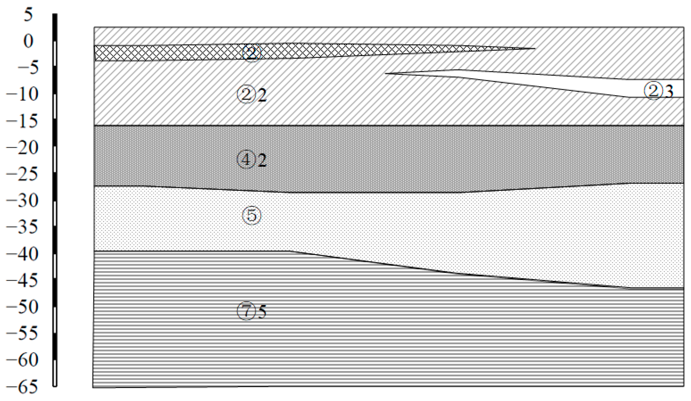
The south anchorage of the North Channel Bridge of the Zhangjinggao Yangtze River Bridge is located on a river island in the middle of the Yangtze River. The site is characterized by a soft soil layer over 50 m thick, exhibiting low strength and poor plasticity. The sandy layers are confined aquifers with high permeability and significant confined water head pressure (see Figure 2 and Table 1). Due to the great excavation depth and the thickness of the impermeable layer, there is a high risk of water inrush from the bottom of the pit during construction.
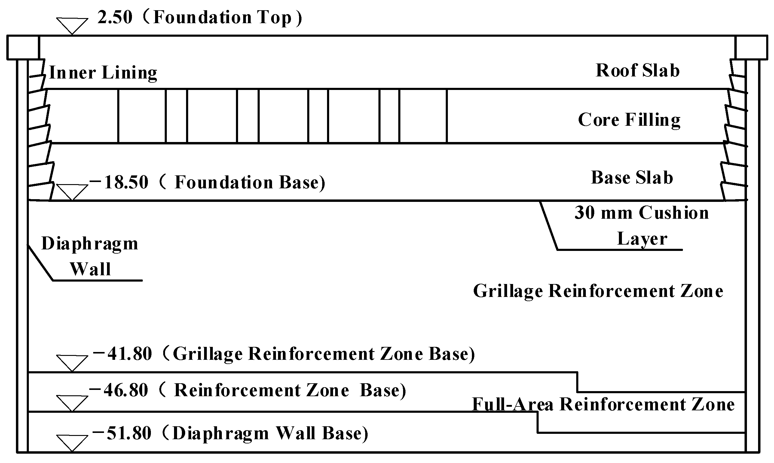
Given these complex geological conditions, the anchorage foundation features a circular underground diaphragm wall with an outer diameter of 90 m and a wall thickness of 1.5 m, complemented by a ring-shaped reinforced concrete lining support structure. By utilizing the circular arch effect of the circular diaphragm wall, the external earth pressure is transformed into axial compressive force within the wall, thereby reducing the bending moment and shear force acting on the diaphragm wall and fully leveraging the excellent compressive strength of concrete [29]. The bottom elevation of the diaphragm wall is −51.8 m. The excavation bottom elevation of the foundation pit is −18.8 m, and the top elevation is +2.5 m. Below the excavation base lies a 28 m thick D-RJP high-pressure rotary jet grouting reinforcement layer, extending to a depth of −46.8 m (see the structural diagram in Figure 3).

2.2. Foundation Reinforcement Overview

Considering both the bearing capacity and anti-inrush design requirements of the anchorage foundation pit, the reinforced ground at the pile locations must meet the following criteria: the unconfined compressive strength of core samples at 28 days must be ≥ 1.8 MPa, at 90 days ≥ 2.7 MPa, and the permeability coefficient must be ≤1 × 10⁻⁶ cm/s.
To mitigate the risk of inrush failure at the pit bottom and ensure adequate bearing capacity while also balancing construction economy, a stratified and zoned reinforcement strategy was implemented. Within the elevation range of −18.8 m to −44.3 m, grid reinforcement was adopted, with high-pressure rotary jet grouting piles arranged in an equilateral triangular pattern. The effective pile diameter is 1.7 m, the center-to-center spacing is 1.7 m, and the piles are tangent to each other. Pile lengths are 23 m and 25.5 m, respectively.
From −44.3 m to −49.3 m, full-area reinforcement was applied. In this zone, piles are also arranged in an equilateral triangular pattern, but with a larger effective diameter of 2.4 m and the same spacing of 1.7 m, forming interlocking piles. Pile lengths in this zone are 5 m and 7.5 m (see Figure 4). The full-area reinforcement zone lies be-neath the grid reinforcement zone, enhancing the control of seepage-induced failure.

2.3. Overview of the D-RJP High-Pressure Rotary Jet Grouting Method

The D-RJP method is a systematically optimized high-pressure jet grouting technique based on the traditional RJP (Rotary Jet Pile) method, as illustrated in Figure 5. Its core improvements include enhancing soil cutting efficiency by increasing the flow rate of the upper-stage high-pressure cutting water, as well as the pressure and flow of auxiliary gas, and eliminating the use of high-pressure air-assisted slurry injections during the lower-stage operation. Instead, a dynamic cement slurry flow control method based on reverse calculation of the effective cement content is adopted to achieve precise material utilization.
Additionally, by increasing the axial spacing between the upper-stage gas–liquid two-phase (air-encapsulated water) spray nozzle and the lower-stage slurry mixture nozzle, the disturbance effect of the upper-stage flow on the lower-stage slurry mixture is significantly reduced, thereby improving the retention rate of cement slurry and the effective cement incorporation rate.
This method produces piles with diameters ranging from 2.0 to 3.0 m (up to a maximum of 3.5 m) and supports 0–360° omnidirectional fan-shaped pile construction. The resulting composite piles are highly homogeneous, with an unconfined compressive strength of approximately 3.5 MPa. It not only effectively reduces material loss due to slurry return but also enables the recycling of construction wastewater.

3. D-RJP High-Pressure Rotary Jet Pile Formation Quality Test

3.1. Test Plan

To evaluate the engineering applicability of the D-RJP Rotary Jet Piles, two sets of field tests were conducted. The first set involved single-pile tests to analyze the effect of lifting speed on the construction parameters that influence the quality of pile formation. Building on the results of the single-pile tests, interlocking pile tests were then carried out. According to the “Technical Code for Ground Treatment of Buildings”, for high-pressure jet grouting piles, the construction parameters must be determined through testing or based on engineering experience, considering soil conditions and reinforcement requirements. Key construction parameters include the water–cement ratio, high-pressure water pressure, auxiliary air pressure, cement grout flow rate, rotation speed, and stroke interval, among others. In these tests, the water–cement ratio of the slurry was adjusted in a gradient range from 0.8 to 1.2. In clay layers, a re-spraying technique was adopted (with the upper nozzles shut off to eliminate gas–liquid disturbances), and the stroke interval was adjusted to examine how these parameters affect the quality of pile formation. The specific test parameters are shown in Table 2.

3.2. Testing Methods

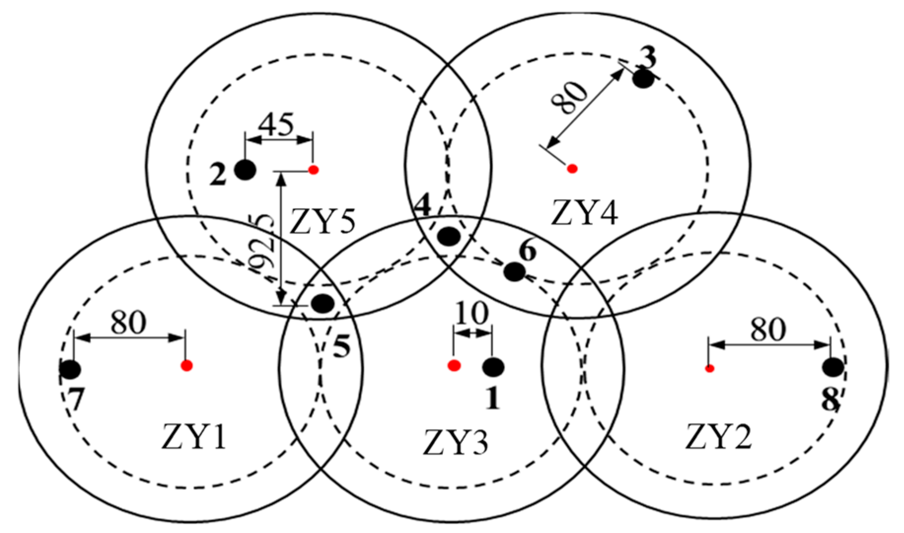
The tests were conducted to evaluate integrity, pile strength, permeability coefficient, reinforced body density, return slurry cement content, the effect of soil displacement, and the friction coefficient. The testing methods and the layout of core sampling points are shown in Table 3 and Figure 6.

3.3. Analysis of Test Results

The results of the single-pile tests indicate that reducing the lifting speed had little effect on the continuity and fragmentation degree of the core samples, suggesting that lifting speed has minimal impact on pile formation quality. This is primarily because the undrained shear strength of the soil layer is too high, resulting in large clay particles at the interface of the cut soil, which hinders proper mixing with the cement slurry. As a result, local clay inclusions and material segregation consistently occurred (see Figure 7). The results of the interlocking pile tests are discussed below.

3.3.1. Pile Diameter

Figure 8 presents the core sampling results over the full depth range (−22 to −49 m), indicating good core integrity at key structural locations, including the pile edges within the clay layer (typical sampling Points 3, 7, and 8), the interface of interlocked double piles (Point 6), and the intersection zone of triple piles (Point 5).

3.3.2. Pile Strength

To analyze the pile strength at the interlocking sections of the interlocking piles, core samples were taken from the pile edges and tested. A comparison between Points 3 (ZY3) and 7 (ZY1) in Figure 9a shows that increasing the water–cement ratio and the lifting increment can effectively enhance the strength of the pile body. Additionally, comparing Figure 9a,b, it is observed that the strength at Edge Points 5 and 6 in the interlocking zone is greater than at non-interlocking Edge Points 3 and 7, indicating that interlocking pile construction is beneficial for improving the edge strength of the piles.
According to the core sample strength test results in Table 4, the average unconfined compressive strength of the core samples in the silty clay layer over 90 days is 5.45 MPa, while that in the silty sand layer is 8.21 MPa. The higher pile strength in the silty sand layer indicates that the construction performance in sandy soil is superior to that in clayey soil. Al-Kinani and Ahmed [32] conducted jet grouting tests to simulate actual field construction conditions, measuring the unconfined compressive strength (UCS) over time. The UCS values of the specimens reached 4.62 MPa at 6 months and 5.52 MPa at 18 months. In contrast, the core samples in the present study achieved UCS values ranging from 5.45 MPa to 8.21 MPa within just 90 days, significantly exceeding the long-term strength reported in the referenced tests. Gökalp and Düzceer [33] conducted continuous coring and integrity testing during the high-pressure jet grouting construction process, reporting an average unconfined compressive strength of 6.8 MPa, which exceeded the required minimum jet grout strength of 3.2 MPa. In the present study, the core sample strength also meets the minimum requirement of 3.2 MPa, further validating the effectiveness of the adopted jet grouting technique.
Due to construction variances in D-RJP implementation and heterogeneous distribution of natural soil strata, spatial variability is observed in core sample strength across measurement points. Consequently, coefficients of variation (COV) were calculated. The results demonstrate that D-RJP-treated soils exhibit COV values of 0.25–0.44 in strength parameters. This statistical characteristic demonstrates the technology’s ability to mitigate spatial variability within strata, confirming its inherent capacity to achieve large-scale uniform engineering improvements.

3.3.3. Permeability Coefficient

To determine the permeability coefficient of the solidified body formed by high-pressure jet grouting piles, permeability tests were conducted on core samples extracted from the construction site. The test procedure followed the falling head permeability test method specified in Standard for Soil Test Methods GB/T 50123-2019 [34].
The permeability test results are shown in Figure 10. The average permeability coefficient of the silty clay layer was 1.67 × 10⁻⁷ cm/s, and that of the silty sand layer was 2.52 × 10⁻⁷ cm/s, both of which meet the design requirements specified in the code (≤1.0 × 10⁻⁶ cm/s). Moreover, Cheng et al. [31] experimentally determined that the permeability coefficient of core samples ranged from 6.4 × 10⁻⁶ to 8.2 × 10⁻⁶ cm/s. In contrast, the permeability coefficient obtained in this study ranges from 1.67 × 10⁻⁷ to 2.52 × 10⁻⁷ cm/s, which is significantly lower than the values reported in their tests, indicating superior performance in terms of impermeability.
As shown in Table 5, the permeability coefficient increases gradually from the center of the pile to its edge, and the data dispersion also increases accordingly. The COV values of the permeability coefficient further demonstrate the inherent potential of this technology to achieve large-scale, uniform engineering improvement.

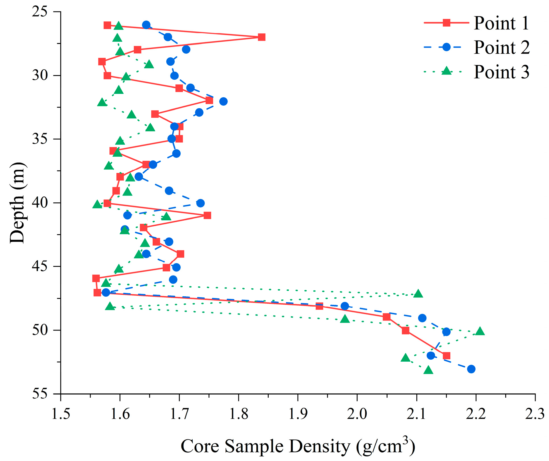
3.3.4. Reinforced Body Density

Core sample density tests were conducted, and the results are shown in Figure 11. The density of core samples from the clay layer was generally higher than that of the samples from the silty sand layer. The average density of reinforced silty clay samples was 1.66 g/cm3, while that of reinforced silty sand samples was 2.08 g/cm3.
Compared with the original soil, the density of the reinforced silty clay pile body decreased by approximately 7.7%, whereas the pile body in the silty sand layer increased by 5.5%. This is because higher undrained shear strength in the soil leads to larger clay particles at the cut soil interface, which impairs bonding with the cement slurry. As a result, the reinforced silty clay has a lower density than the silty sand.

3.3.5. Return Slurry Cement Content

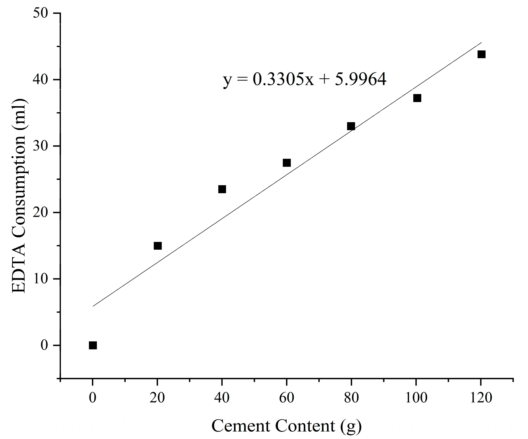
To determine the cement content in the return slurry, geological drilling was first conducted on-site to collect samples. Titration tests were performed on samples mixed with natural soil and cement at various proportions: 30%, 40%, 45%, 50%, 55%, 60%, 70%, and pure cement. Two parallel tests were conducted for each mix ratio. Based on the titration results, an EDTA standard curve was plotted as y = 0.3305x + 5.9964, as shown in Figure 12.
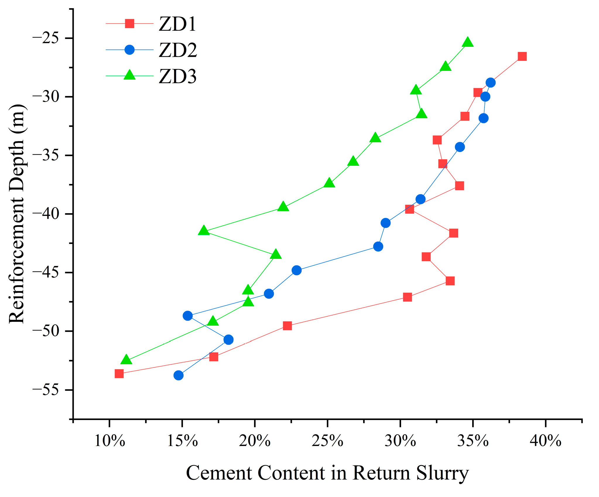
Titration tests were also performed on return slurry samples from different depths of single piles ZD1, ZD2, and ZD3. As shown in Figure 13, the cement content in the return slurry generally increases from bottom to top with increasing depth, while it decreases with higher lifting speeds. The return slurry in the silty clay layer had a higher overall cement content than that in the sandy soil layer. The average cement content in the return slurry from the silty clay layer was 27%, whereas that from the sandy soil layer was 18%. Shinsaka and Yamazaki [30] evaluated the extent of soil disturbance, grouting quality, and construction efficiency in the jet grouting process by analyzing the cement content and composition of the discharged slurry through sieve analysis. Their study reported the cement content in the return slurry ranging from 28% to 66%. In contrast, the maximum average cement return ratio observed in this study was 27%, which is even lower than the minimum value reported in their research, indicating a more favorable quality of jet grout columns.
This difference is attributed to the presence of pore water in the silty sand, which retains more cement slurry during the high-pressure jet grouting process, thereby reducing the cement content in the return slurry. Additionally, as shown in Figure 13, when other construction parameters remain constant, the cement content in the return slurry decreases as the lifting speed increases.

3.3.6. Soil Squeezing Effect

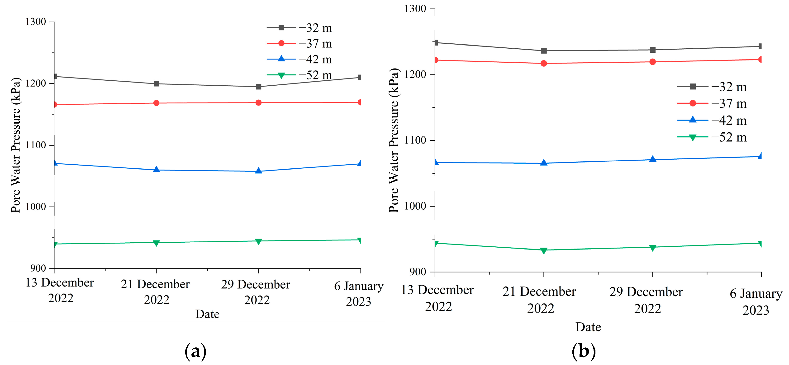
Two pore water pressure tubes, KX1 and KX2, were installed at distances of 1.5 m and 3 m from the edge of the rotary jet pile ZY3. Vibrating wire piezometers were placed at 5 m intervals along the depth direction. Seven days after the completion of the interlocking pile construction, pore water pressure was measured at different depths at both observation points.
As shown in Figure 14, the largest increase in pore water pressure was observed at a depth of −42 m in borehole KX2, increasing by a total of 1.2% over 22 days after construction. However, the pore water pressures at the remaining measurement points remained largely unchanged and stable, indicating that the D-RJP ultra-high-pressure rotary jet grouting process leads to minimal soil squeezing effect and does not impact the surrounding environment.
The primary reason for this is that the borehole diameter was increased from 20 cm to 65 cm, which effectively cleared the return slurry channels, reduced the accumulation of high-pressure gas within the borehole, and facilitated the upward displacement of waste soil. This, in turn, reduced internal ground stress and minimized the significant soil squeezing effects on the surrounding area.

3.3.7. Friction Coefficient

Samples were taken at distances of 5 cm, 45 cm, and 80 cm from the pile axis for indoor direct shear tests. The friction coefficient at the base interface was tested using disk specimens with a diameter of 61.8 mm and a height of 20 mm.
The test was conducted with a direct shear apparatus to measure the interface friction coefficient between concrete and cement-treated soil. Three levels of vertical stress were applied: 500 kPa, 1000 kPa, and 1500 kPa. The peak horizontal shear force was recorded, and the average interface shear stress was calculated according to:
τ = F h / A s
τ is the average interface shear stress; F h refers to the maximum shear force recorded during the direct shear test when sliding or failure occurs at the interface; and A s is the contact area of the specimen interface during shearing, used to convert the total shear force into shear stress.
The test results show that the average friction coefficient at 5 cm from the pile axis is 0.47, at 45 cm is 0.46, and at 80 cm is 0.44—all exceeding the design specification requirement of 0.37, as shown in Table 6.

4. D-RJP High-Pressure Rotary Jet Pile Artificial Composite Foundation Bearing Capacity and Direct Shear Test

To comprehensively evaluate the mechanical performance of the artificial composite foundation formed by D-RJP high-pressure jet grouting piles and ensure its bearing capacity in ultra-deep foundation pit projects for suspension bridge anchorages, this study conducted bearing capacity and direct shear tests on the composite foundation. The ultimate bearing capacity was determined through static plate load tests, and the shear strength parameters-including internal friction angle and cohesion-were analyzed based on direct shear tests. These tests systematically revealed the bearing characteristics and shear resistance of the artificial composite foundation under complex geological conditions, providing experimental evidence and data support for its applicability and reliability.

4.1. Composite Foundation Bearing Capacity Test

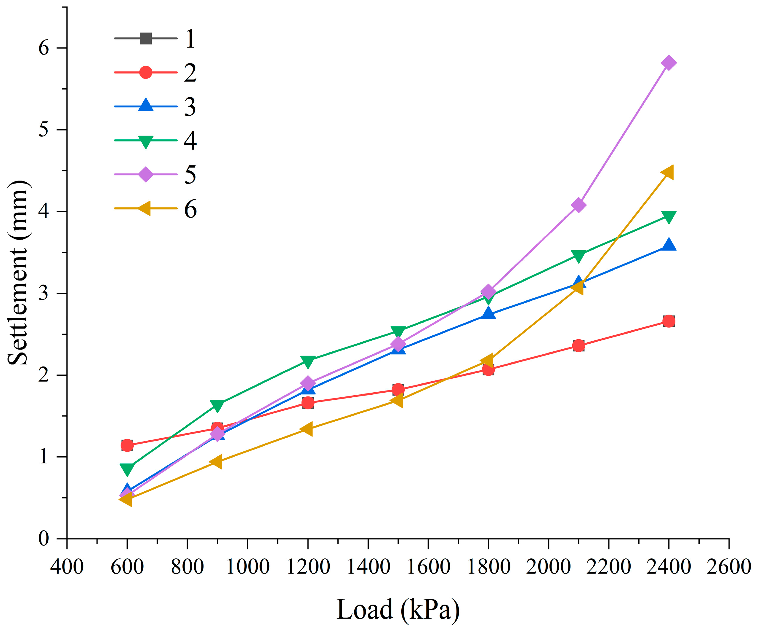
The basic characteristic value of foundation bearing capacity was determined through deep plate load tests. The test involved load plate tests on six piles. Among them, Test Points 1 (4) and 3 (6) were located at the interlocking sections of the piles, while Test Points 2 (5) were located at the pile center, as shown in Figure 15.
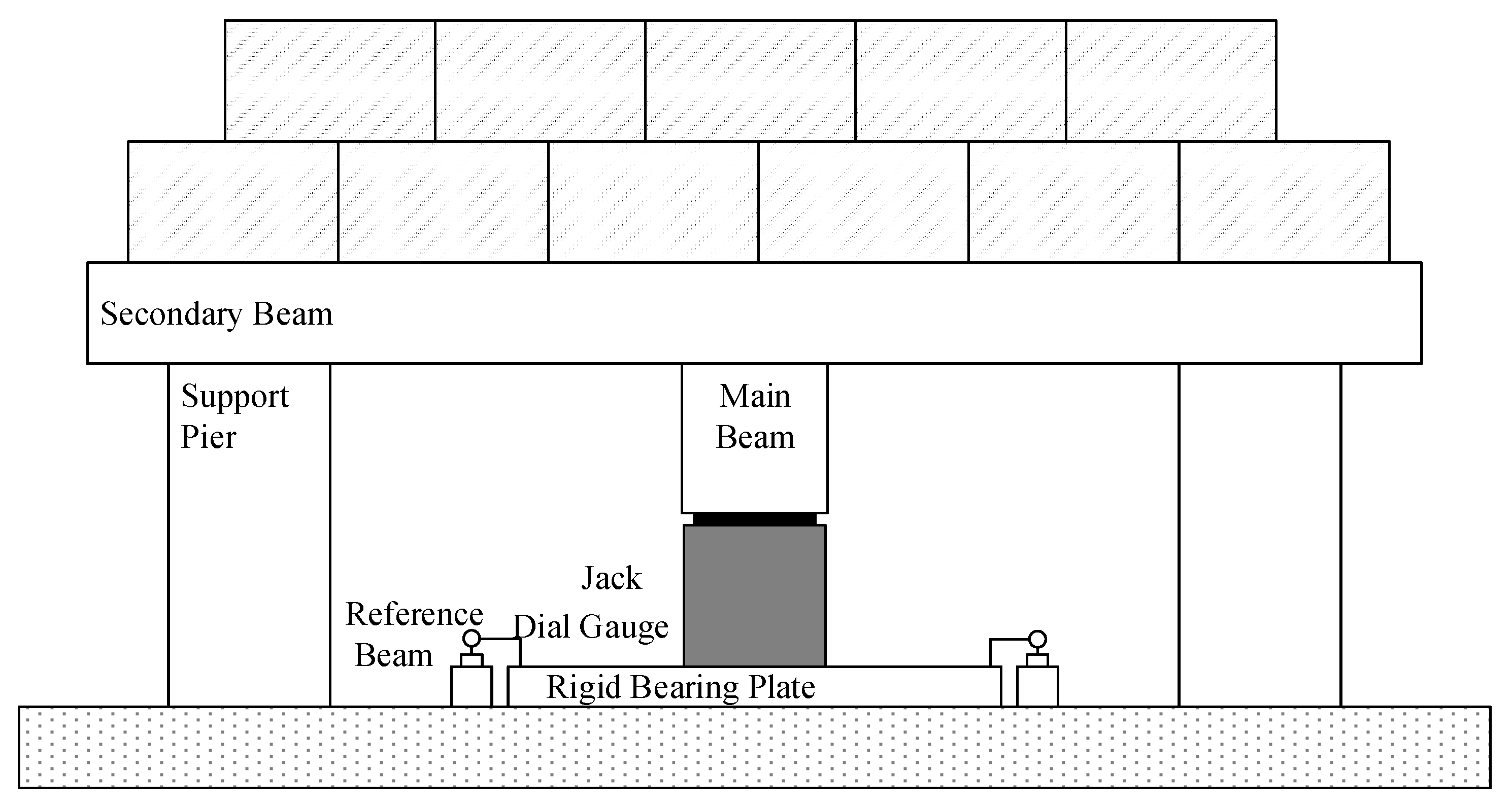
A counterforce system was constructed using a weighted platform, with counterweights placed on a load-bearing steel beam. A hydraulic jack was used to apply the load, while a static load tester controlled the load levels. The displacement sensors measured the settlement of the foundation, as shown in Figure 16.
The loading was divided into seven stages: the first stage applied a load of 1205.8 kN, followed by six stages, each increasing by 602.9 kN, applied on a circular rigid loading plate with a diameter of 80 cm. For each loading stage, settlement readings were taken at 10, 20, 30, 45, and 60 min and then every 30 min thereafter. If, under any loading stage, the hourly settlement over two consecutive hours was less than 0.1 mm, the foundation was considered to have stabilized, and the next load stage could be applied.
Based on the test data, vertical load-settlement (P-S) curves were plotted, as shown in Figure 17. When a distinct steep drop appears in the P-S curve, the load value at the start of the steep drop segment is taken as the ultimate bearing capacity. If no obvious steep drop segment is observed, the ultimate bearing capacity is determined according to the deformation control criterion of the foundation, using the load corresponding to a settlement of s = 0.010 b (where b is the diameter of the bearing plate 80 cm), with the condition that this load value should not exceed half of the maximum test load.
The test results showed that at Test Points 1 to 4, no distinct steep change appeared even when the applied load reached the maximum test load of 2400 kPa. At Test Points 5 and 6, the steep drop segments occurred after 2100 kPa. In all cases, the ultimate bearing capacities exceeded the design specification requirement of 1200 kPa.

4.2. Direct Shear Test at the Foundation Base

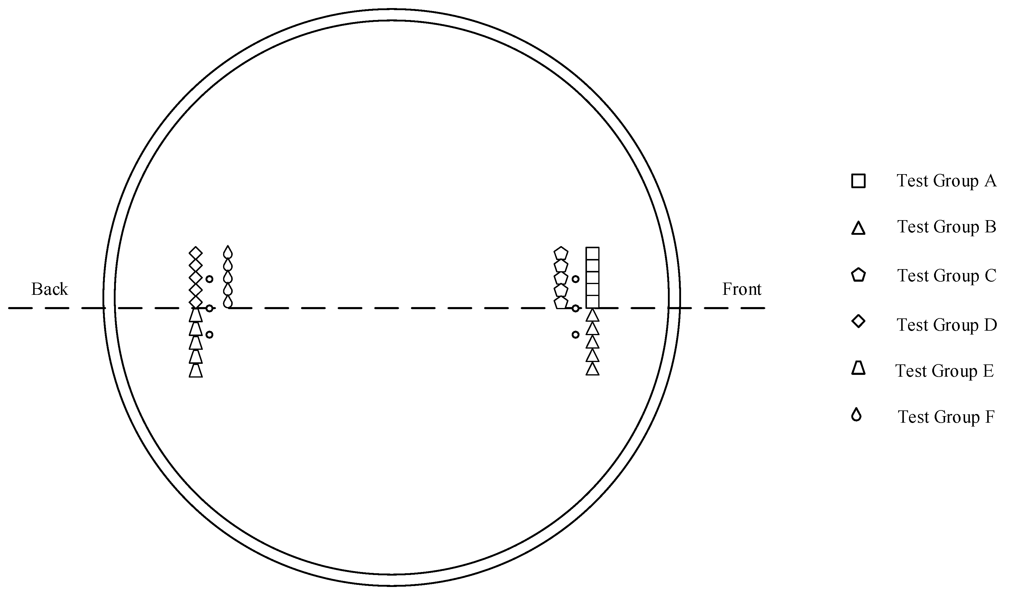
The direct shear test at the foundation base was conducted to determine the internal friction angle and cohesion of the composite foundation. The test consisted of six groups of measurement points, with five measurement points assigned to each group, as illustrated in Figure 18.
Different levels of normal load were applied to each specimen, with each specimen subjected to three stages of normal loading. After applying the first level of normal load, the vertical displacement under that load was immediately recorded, followed by a second reading taken 5 min later. Then, the next level of load was applied, and the procedure was repeated.
Once the predetermined maximum normal load was applied, displacement readings were taken every 5 min. When the difference between two consecutive displacement readings was less than 0.01 mm, the specimen was considered to have reached relative stability. At this point, the shear testing apparatus was set up, and the shear test was initiated.
The maximum shear load was set to 50% of the corresponding normal load. During shearing, the estimated maximum shear load was applied in five incremental stages. Each stage was applied every 5 min, with displacement readings taken before and after each stage. The test was stopped when shear failure occurred at the interface between the specimen and the rock foundation.
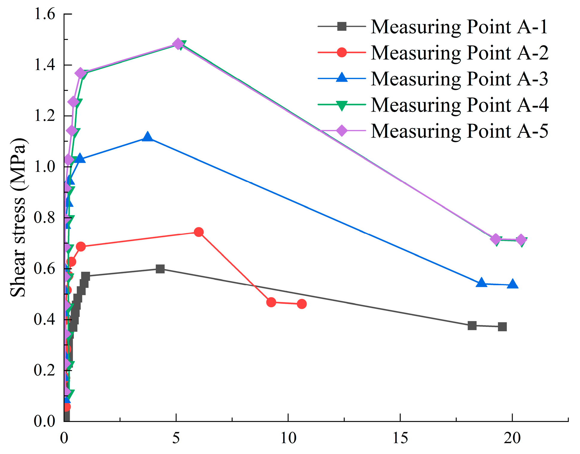
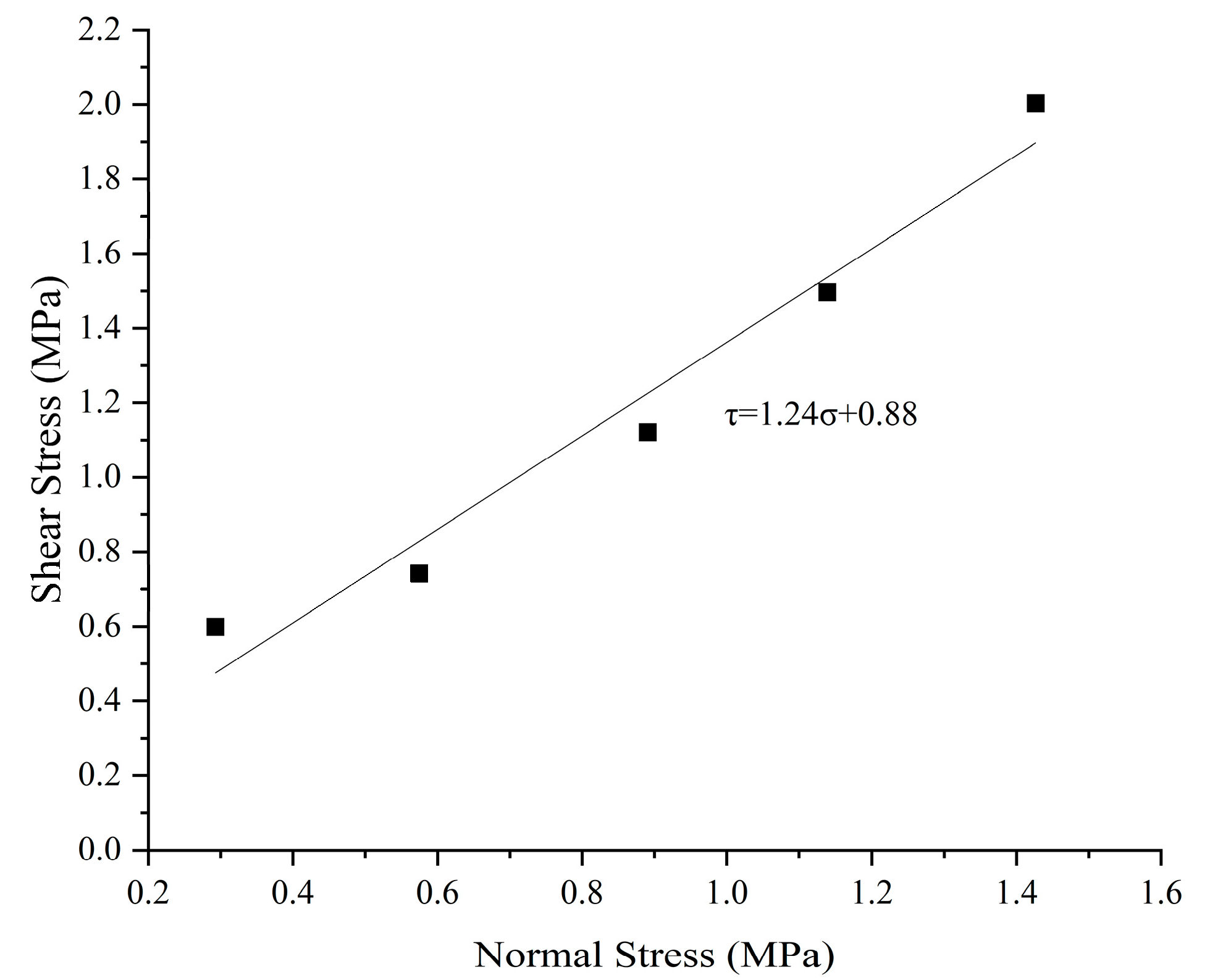
Finally, the direct shear test results for each test group were processed using the least squares method to fit a straight line of variation in shear stress (τ) with respect to normal stress (α), from which the friction coefficient and cohesion were determined. Group A is used here as an example, as illustrated in Figure 19 and Figure 20.
Table 7 summarizes the shear strength parameters of the composite foundation obtained from direct shear tests under working conditions. The cohesion values range from 180 to 290 kPa, while the internal friction angle ranges from 24.23° to 26.1°. Among the test groups, Group C exhibited the highest cohesion at 290 kPa, and Group E showed the highest internal friction angle at 26.1°. Overall, all test groups demonstrated consistent and stable shear strength performance, confirming that the D-RJP composite foundation possesses sufficient resistance to shear deformation under service loads.

5. Conclusions

This study, based on the South Anchorage Project of the Zhangjinggao Yangtze River Bridge North Navigation Channel, systematically investigated the application of D-RJP high-pressure rotary jet grouting technology in ultra-deep foundation pit reinforcement under complex geo-logical conditions, including deep soft soil and high groundwater levels. Through systematic indoor core sampling tests and on-site mechanical performance tests, the reinforcement effect, structural performance, and construction adaptability were comprehensively analyzed. The main conclusions are as follows:
(1)
The core samples of the high-pressure jet grout columns formed by the D-RJP process exhibited good integrity and continuity; in the silty sand layer, the 90-day unconfined compressive strength of the column core sample reached 8.21 MPa, and in the silty clay layer, it reached 5.45 MPa, which is significantly higher than the expected strength level and meets the foundation strength requirements of the foundation pit.
(2)
The measured maximum average permeability coefficient of the high-pressure jet grout columns was 2.52 × 10⁻⁷ cm/s, which is significantly better than the expected value of 1.0 × 10⁻⁶ cm/s; the permeability coefficient showed an increasing trend from the center to the edge of the column, indicating the good grout diffusion uniformity and effectively improving the anti-seepage and anti-water inrush performance of the pit bottom.
(3)
The density of the foundation soil changed, and the foundation interface friction performance was excellent. After reinforcement, the average density of the silty clay layer sample decreased by 7.7%, while the silty sand layer increased by 5.5%, indicating changes in soil compactness. The foundation interface friction coefficient ranged from 0.44 to 0.47, which was significantly higher than the expected value of 0.37, indicating good interface friction performance.
(4)
The material utilization efficiency was high, and construction disturbance control was effective. The grout return analysis showed that the cement return rates of the core samples from the high-pressure jet grout columns in the silty clay and silty sand layers were 27% and 18%, respectively. No obvious soil squeezing effect was seen during the construction process. The D-RJP process can enable green, efficient, full-process quality and disturbance control during construction.
(5)
The bearing capacity and shear strength of the high-pressure jet grout composite foundation met expectations. The static load test results showed that the characteristic bearing capacity of the composite foundation exceeded 1200 kPa, meeting the expected foundation bearing capacity requirements. The direct shear tests indicated that the minimum internal friction angle of the composite foundation was 24.23°, and the minimum cohesion was 180 kPa. The overall mechanical performance was excellent, providing reliable shear resistance.
Nevertheless, this study exhibits limitations in validating the overall ground improvement performance exclusively through core sampling and localized in situ tests. Consequently, it inadequately addresses potential site-specific anomalies at test locations, holistic scale effects within improved zones, and the sustained verification of long-term performance. Future research will focus on these critical aspects to further investigate the scalability and long-term stability of D-RJP technology under complex geotechnical conditions.

Author Contributions

Conceptualization: X.Z., W.Z. (Wenqing Zhao) and G.D.; methodology: X.Z., W.Z. (Wenqing Zhao) and Z.C.; software: W.Z. (Wenqing Zhao), J.Z., S.F., Z.C. and W.Z. (Wenbo Zhu); validation: W.Z. (Wenqing Zhao), J.Z., S.F., Z.C. and W.Z. (Wenbo Zhu); formal analysis: X.Z. and W.Z. (Wenqing Zhao); investigation: X.Z. and W.Z. (Wenqing Zhao); resources: X.Z.; data curation: X.Z., W.Z. (Wenqing Zhao) and G.D.; writing—original draft preparation: X.Z., W.Z. (Wenqing Zhao), G.D., J.Z., S.F., Z.C. and W.Z. (Wenbo Zhu); writing—review and editing: X.Z., W.Z. (Wenqing Zhao), G.D., J.Z., S.F., Z.C. and W.Z. (Wenbo Zhu); visualization: X.Z., W.Z. (Wenqing Zhao), J.Z. and S.F.; supervision: X.Z., W.Z. (Wenqing Zhao), G.D., J.Z., S.F., Z.C. and W.Z. (Wenbo Zhu); project administration: X.Z., G.D., J.Z., S.F., Z.C. and W.Z. (Wenbo Zhu); funding acquisition: X.Z. and G.D. All authors have read and agreed to the published version of the manuscript.

Funding

This research was funded by the National Natural Science Foundation of China (52378328, 52208333), the Research Fund for Advanced Ocean Institute of Southeast University (Key Program KP202404; General Program GP202403), and the Scientific & Technological Research and Development Project of Road & Bridge International Co., Ltd. (RP2023018895).

Institutional Review Board Statement

Not applicable.

Informed Consent Statement

Not applicable.

Data Availability Statement

The raw data supporting the conclusions of this article will be made available by the authors on request.

Acknowledgments

The authors sincerely appreciate the valuable contributions of the editors and reviewers to this work. We extend our gratitude to the editorial team, for their professional guidance and efficient coordination throughout the publication process. We extend our special thanks to the anonymous reviewers for their meticulous evaluation, constructive feedback, and insightful suggestions, which significantly strengthened the rigor and clarity of this manuscript. Their expertise and dedication have been instrumental in refining both the technical content and the presentation of this study.

Conflicts of Interest

Authors Xiaoliang Zhu, Sheng Fang and Junchen Zhao were employed by the company Road & Bridge International Co., Ltd. The remaining authors declare that the research was conducted in the absence of any commercial or financial relationships that could be construed as a potential conflict of interest.

References

  1. Yamazaki, J.; Chao, K.C.; Wong, R.; Wang, M. Development of the Jet Grouting Method: Evolutionary History, Mechanism Insights, Innovative Approaches, and Future Prospects. Geotech. Eng. 2024, 55, 11–23. [Google Scholar] [CrossRef]
  2. Botto, G. Developments in the techniques of jet-grouting. In XII Ciclo di Conferenze di Geotecnica; Associazione Geotecnica Italiana: Torino, Italy, 1985. [Google Scholar]
  3. Inazumi, S.; Shakya, S. A Comprehensive Review of Sustainable Assessment and Innovation in Jet Grouting Technologies. Sustainability 2024, 16, 4113. [Google Scholar] [CrossRef]
  4. Ho Chu, E. Fluid-Soil Interaction Model for Jet Grouting. In Grouting for Ground Improvement; Proceedings; ASCE: Reston, VA, USA, 2012; pp. 1–10. [Google Scholar]
  5. Zhao, L.-S.; Qi, X.; Tan, F.; Chen, Y. A new prediction model of the jet grouting column diameter for three jet grouting systems. Comput. Geotech. 2023, 163, 105753. [Google Scholar] [CrossRef]
  6. Liu, G.; Wang, B. Study on the Effect of Jet Grouting Pile Reinforcing Soft Soil Subgrade. Adv. Mater. Res. 2012, 594–597, 1420–1428. [Google Scholar] [CrossRef]
  7. Shan, Y.; Luo, J.; Wang, B.; Zhou, S.; Zhang, B. Critical application zone of the jet grouting piles in the vicinity of existing high-speed railway bridge in deep soft soils with medium sensibility. Soils Found. 2024, 64, 101407. [Google Scholar] [CrossRef]
  8. Shen, S.; Wang, Z.; Cheng, W. Estimation of lateral displacement induced by jet grouting in clayey soils. Géotechnique 2017, 67, 621–630. [Google Scholar] [CrossRef]
  9. Liu, D.; Ye, Z.-W.; Xie, W.-J.; Gao, J.-L.; Hu, S.-T.; Li, Y.; Chen, F. Numerical simulation study on the construction of cut off walls using high-pressure jet grouting based on SPH method. Front. Earth Sci. 2024, 12, 1491583. [Google Scholar] [CrossRef]
  10. Liang, M.; Jin, C.; Hou, J.; Wang, M.; Shi, Y.; Dong, Z.; Yang, X.; Zhou, J.; Cai, J. Research and Application of High-Pressure Rotary Jet Method in the Seepage Treatment of Heavy Metal Tailing Ponds of Southwest China. Materials 2023, 16, 3450. [Google Scholar] [CrossRef] [PubMed]
  11. Guan, C.; Yang, Y. Field study on the waterstop of the rodin jet pile method in a water-rich sandy gravel stratum. Appl. Sci. 2019, 9, 1709. [Google Scholar] [CrossRef]
  12. Fan, H.; Xu, Q.; Lai, J.; Liu, T.; Zhu, Z.; Zhu, Y.; Gao, X. Stability of the loess tunnel foundation reinforced by jet grouting piles and the influence of reinforcement parameters. Transp. Geotech. 2023, 40, 100965. [Google Scholar] [CrossRef]
  13. Brill Gary, T.; Burke George, K.; Ringen Alan, R. A Ten-Year Perspective of Jet Grouting: Advancements in Applications and Technology. In Grouting and Ground Treatment; Proceedings; ASCE: Reston, VA, USA, 2012; pp. 218–235. [Google Scholar]
  14. Wang, J.-L.; Wang, J.-W. The Application of Jet Grouting in Shanghai Foundation Pit Projects; Missouri University of Science and Technology: Rolla, MO, USA, 2004. [Google Scholar]
  15. Daramalinggam, J.; Annam, M.K. Overcoming Geotechnical Challenges in Rail and Metro Projects Using Ground Improvement. In Geotechnics for Transportation Infrastructure: Recent Developments, Upcoming Technologies and New Concepts; Springer: Singapore, 2019; Volume 2, pp. 539–556. [Google Scholar]
  16. Tang, K.; Cheng, L.; Wang, X.; Pan, C.; Lin, L.; Dong, L.; Li, B. Research on Digital Monitoring Technology for Airport High-Pressure Rotary Jet Piles. IEEE Access 2023, 11, 112731–112752. [Google Scholar] [CrossRef]
  17. Wang, T.; Liu, X.; Liu, L.; Xiong, W.; Li, Z. Research on the Reinforcement Effect and Bearing Characteristics of High-Pressure Jet-Grouting Piles on Covered Road Composite Ground in Landfill Sites. Buildings 2024, 14, 444. [Google Scholar] [CrossRef]
  18. Njock, P.G.A.; Chen, J.; Modoni, G.; Arulrajah, A.; Kim, Y.H. A review of jet grouting practice and development. Arab. J. Geosci. 2018, 11, 459. [Google Scholar] [CrossRef]
  19. Xiong, W.; Jiang, C.; Wang, T.; Wang, R.; Zhou, X. Safety-Margin Design for Gravity-Type Anchorage of Suspension Bridges over 2,000 m Long Based on Target Reliability. J. Bridge Eng. 2024, 29, 04024003. [Google Scholar] [CrossRef]
  20. Yi, Z.; Zhang, Q.; Huang, X.; Xu, A.; Ning, S.; Shen, Q.; Ru, X.; Liu, Y.; Liu, Y. Analysis of Monitoring Priorities for Long-Span Suspension Bridges in Complex Environments. ce/papers 2025, 8, 1563–1579. [Google Scholar] [CrossRef]
  21. Wang, C.; Han, H.; Wang, H.; Zhang, X.; Liu, X.; Leng, X.; Qin, W.; Fang, K. Load-bearing behaviors of the composite gravity-type anchorage: Insights from physical model and numerical tests. Eng. Fail. Anal. 2025, 167, 108959. [Google Scholar] [CrossRef]
  22. Wardrop, J.; Pennington, D. Use of stone columns as ground improvement beneath a bridge and embankment—A case study. Aust. Geomech. J. 2003, 38, 135–140. [Google Scholar]
  23. Xu, H.; Li, S. Safety Analysis of Deep Foundation Excavation in Water-Rich Soft Soils Based on BIM. Math. Probl. Eng. 2020, 2020, 4923984. [Google Scholar] [CrossRef]
  24. Wang, W.; Han, Z.; Deng, J.; Zhang, X.; Zhang, Y. Study on soil reinforcement param in deep foundation pit of marshland metro station. Heliyon 2019, 5, e02836. [Google Scholar] [CrossRef] [PubMed]
  25. Xu, X.B.; Hu, Q.; Huang, T.M.; Chen, Y.; Shen, W.M.; Hu, M.Y. Seepage failure of a foundation pit with confined aquifer layers and its reconstruction. Eng. Fail. Anal. 2022, 138, 106366. [Google Scholar] [CrossRef]
  26. Li, Z.; Zhao, J.; Hu, K.; Li, Y.; Liu, L. Adaptability Evaluation of Rotary Jet Grouting Pile Composite Foundation for Shallow Buried Collapsible Loess Tunnel. Appl. Sci. 2023, 13, 1570. [Google Scholar] [CrossRef]
  27. Borges, J.; Gonçalves, M. Jet-grout column-reinforced soft soils incorporating multilayer geosynthetic-reinforced platforms. Soils Found. 2016, 56, 57–72. [Google Scholar] [CrossRef]
  28. Yi, Z.; Lv, X.; Jiao, H.; Duan, R.; Shi, X.; Wu, H. Water Inrush Control and Effect Evaluation of Weak Fault Fracture Zones in Fushui High-Speed Railway Tunnel. In Application and Development of Data Simulation and Mechanical Analysis in Civil Engineering; Springer: Cham, Switzerland, 2025; pp. 370–381. [Google Scholar]
  29. Zhai, J.Q.; Wang, Q.; Wang, S.S.; Zhang, Z.B.; Wan, J.C. Design, construction, and monitored behavior of two large-diameter cylindrical diaphragm walls on an offshore reclamation island. In IOP Conference Series: Earth and Environmental Science; IOP Publishing: Bristol, UK, 2024; Volume 1336, p. 012016. [Google Scholar] [CrossRef]
  30. Shinsaka, T.; Yamazaki, J. Development of high-speed type jet grouting method. In Proceedings of the Geotechnics for Sustainable Development, Hanoi, Vietnam, 28–30 November 2013; Volume 28, p. 29. [Google Scholar]
  31. Cheng, S.-H.; Liao, H.-J.; Yamazaki, J.; Wong, R.K.N.; Iwakubo, T. Alignment of Vertical and Inclined Jet Grout Columns for Waterproofing. Geotech. Test. J. 2020, 43, 325–338. [Google Scholar] [CrossRef]
  32. Al-Kinani, A.; Ahmed, M. Field study of the effect of jet grouting parameters on strength based on tensile and unconfined compressive strength. In IOP Conference Series: Materials Science and Engineering; IOP Publishing: Bristol, UK, 2020; Volume 737, p. 012083. [Google Scholar] [CrossRef]
  33. Gökalp, A.; Düzceer, R. Ground Improvement by jet grouting technique for foundations of a natural gas combined cycle power plant in Turkey. In Proceedings of the Ninth International Conference & Exhibition on Piling and Deep Foundations, DFI, Nice, France, 16–18 November 2022. [Google Scholar]
  34. GB/T 50123-2019; Standard for Geotechnical Testing Method. National Standardization Administration of China: Beijing, China, 2019.
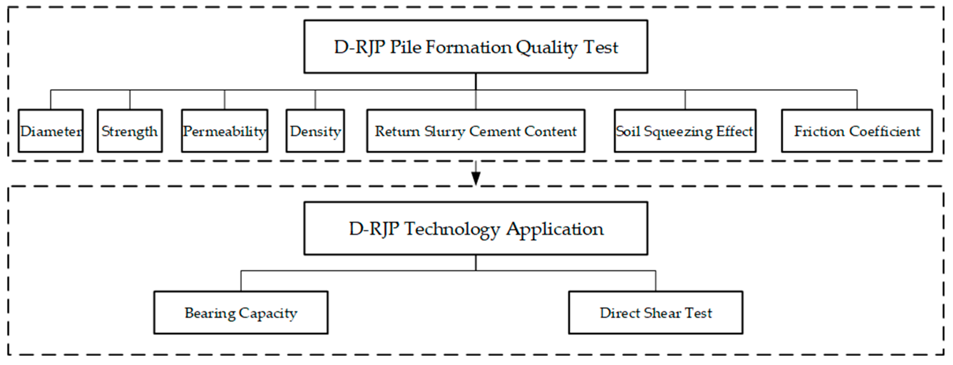
Figure 1. Research framework diagram.
Applsci 15 08985 g001
Figure 2. Geological cross-section.
Applsci 15 08985 g002
Figure 3. Anchorage foundation structure diagram.
Applsci 15 08985 g003
Figure 4. Pile layout diagram: (a) grid reinforcement zone; (b) full-area reinforcement zone.
Applsci 15 08985 g004
Figure 5. D-RJP schematic diagram.
Applsci 15 08985 g005
Figure 6. Layout of coring points.
Applsci 15 08985 g006
Figure 7. Photos of core sample in single-pile test: (a) ZD1; (b) ZD3.
Applsci 15 08985 g007
Figure 8. Photos of core sample in interlocking pile test: (a) Point 3; (b) Point 5; (c) Point 6; (d) Point 7; and (e) Point 8.
Applsci 15 08985 g008aApplsci 15 08985 g008b
Figure 9. 90 days of unconfined compressive strength of the core sample: (a) non-interlocked zone at pile edge; (b) interlocked zone at pile edge.
Applsci 15 08985 g009
Figure 10. Core sample permeation test results.
Applsci 15 08985 g010
Figure 11. Pile core sample density test results.
Applsci 15 08985 g011
Figure 12. EDTA standard curve.
Applsci 15 08985 g012
Figure 13. Cement content in the return slurry for test piles ZD1 to ZD3.
Applsci 15 08985 g013
Figure 14. Variation chart depicting pore water pressure in different depths of observation hole: (a) KX1 observation well; (b) KX2 observation well.
Applsci 15 08985 g014
Figure 15. Schematic diagram of foundation bearing capacity test locations.
Applsci 15 08985 g015
Figure 16. Test schematic diagram.
Applsci 15 08985 g016
Figure 17. Vertical load-settlement (P-S) curves.
Applsci 15 08985 g017
Figure 18. Test point layout diagram.
Applsci 15 08985 g018
Figure 19. Shear stress–displacement curve of Group A.
Applsci 15 08985 g019
Figure 20. Shear stress–normal stress curve of Group A.
Applsci 15 08985 g020
Table 1. Physical and mechanical properties of soil layers.
No.Soil Typeω (%)IlQuick Direct Shear TestPermeability Coefficient
(×10−6 cm/s)
SPT N-Value
cq (kPa)φq (°)
Silty sand25.63.127.9636.36.3
②2Silty clay35.01.1312.87.90.2314.5
④2Silty clay34.21.0611.57.60.2316.8
Silty clay31.30.8814.59.20.2319.1
⑦5Silty sand17.93.329.01351.332.5
Table 2. Test parameters [30,31].
ParameterSingle-Pile TestInterlocked Pile Test
ZD1ZD2ZD3ZY1ZY2ZY3ZY4ZY5
Pilot hole diameter (mm)650650
Water–cement ratio1110.80.80.8
High-pressure water pressure (MPa)3838 (0)
High-pressure water flow rate (L/min)200200 (0)
Auxiliary air pressure (MPa)1.051.05 (0)
Auxiliary air flow rate (Nm3/min)55.0 (0)
Cement grout pressure (MPa)4040 (40)
Cement grout flow rate (L/min)9595 (40)
Lifting speed (min/m)202530Grid zone (silty clay): 20 (10)
Interlocked zone (silty sand): 25
Stroke interval (mm)252533
Rotation speed (r/step)44 (2)
Note: In the interlocking pile tests, the parameters in parentheses indicate the construction parameters during the re-spraying stage.
Table 3. Test detection method.
No.Test ObjectiveTest MethodRepresentative Core Sample Numbers
1Jet grouting pile diameterCore drilling3, 5, 6, 7, 8
2Pile body quality inspectionCore drilling1, 2, 3, 5, 6, 7
3Pile permeability coefficientLaboratory permeability test1, 2, 3, 4, 5, 6, 7
Table 4. Core sample strength test results.
Point NumberAverage Strength (MPa)Range (MPa)Standard Deviation (MPa)Coefficient of Variation
Point 17.053.21–12.542.210.31
Point 25.62.69–10.421.950.35
Point 34.72.03–9.871.780.38
Point 54.321.72–7.081.490.35
Point 64.982.02–9.832.180.44
Point 73.011.69–4.650.770.25
Silty Clay5.451.950.36
Silty Sand8.212.770.34
Table 5. Analysis of core sample permeability test results.
Sampling LocationAverage Permeability Coefficient (cm/s)Range (cm/s)Standard Deviation (cm/s)Coefficient of Variation
Core axis1.09 × 10−70.62−1.913.64 × 10−80.33
Middle section1.64 × 10−70.78−2.127.92 × 10−80.48
Edge2.82 × 10−70.68−5.421.82 × 10−70.65
Table 6. The test results of the average friction coefficient.
LocationNo.ElevationVertical Stress (kPa)Friction CoefficientAverageStandard DeviationRange
50010001500
5 cm1−23.4275.6548.2794.50.520.470.0250.43–0.52
2−23.9256.4489.7728.90.47
3−24.9247.6478.6700.20.45
4−25.3214.8445.2645.10.43
5−33.5236.5468.2699.10.46
6−34.2208.9439.4689.50.48
7−44.9238.5489.7721.50.48
8−45.2204.8445.8699.40.49
45 cm1−23.2242.6499.6706.40.460.460.0180.43–0.49
2−24.3256.4489.7728.90.47
3−24.8242.6499.6706.40.46
4−25.3232487.6721.50.49
5−26.5248.7469.7714.90.46
6−37.3214.8445.2645.10.43
80 cm1−22.2264.3438.4704.10.440.450.0160.43–0.48
2−23.1269.4458.7716.30.45
3−23.3259.8467.3720.40.46
4−23.9214.8445.2645.10.43
5−44.5236.5468.2699.10.46
6−46.2221.3447.6703.40.48
Table 7. Strength parameters from direct shear test.
Test GroupCohesion (kPa)Internal Friction Angle (°)
A20024.23
B22025.64
C29024.7
D22025.64
E19026.1
F18025.64
Disclaimer/Publisher’s Note: The statements, opinions and data contained in all publications are solely those of the individual author(s) and contributor(s) and not of MDPI and/or the editor(s). MDPI and/or the editor(s) disclaim responsibility for any injury to people or property resulting from any ideas, methods, instructions or products referred to in the content.