1. Introduction
The stability of underground mine workings remains one of the key engineering challenges in the design and operation of mining systems under complex geological conditions. This issue is particularly relevant in the Karaganda Coal Basin, where workings are developed at depths of up to 900 m under conditions of intense fracturing, variable lithology, and high gas content. The application of traditional design methods such as nomograms, empirical formulas, and normative documents [
1,
2,
3,
4,
5,
6] under such settings often leads to significant inaccuracies and uncertainty.
To address these challenges, this study proposes an architecture for an intelligent expert system designed to assess excavation stability and recommend appropriate rock bolt support parameters.
Unlike conventional design approaches, the system integrates numerical modeling, formalized engineering rules, and a structured knowledge base validated against field observations.
The architecture is designed to support decision making in geomechanically heterogeneous environments and can serve as a foundation for future digital twin systems in mining.
The problem of excavation stability has been extensively addressed in both domestic and international research. In Kazakhstan, notable contributions include the work of S.B. Aliev [
7], who developed support calculation methods for coal mines, and V.F. Dyomin [
8,
9,
10,
11], a prolific author on rock bolt reinforcement in challenging geological settings. Other significant studies include those by A.A. Baryakh [
12] on the behavior of salt rocks and E.S. Kiselev [
13], an expert in support technologies.
Internationally, important research includes John P. Harrison’s work on the numerical modeling of rock masses [
14]; the development of the Hoek–Brown failure criterion by Evert Hoek [
15]; digital geotechnical modeling by Feng Xia-Ting [
16]; and Hani Mitri’s studies on excavation stability [
17].
In recent years, intelligent decision-support tools for rock support design have emerged, such as RockMass AI [
18], the AI-GIS platform [
19], neuro-fuzzy systems [
20,
21], and hybrid approaches combining numerical modeling with machine learning algorithms like Random Forest, XGBoost, and multilayer perceptron (MLP) [
22,
23,
24]. These systems emphasize the importance of accounting for nonlinear relationships among geomechanical parameters, such as rock strength, fracturing, moisture content, and depth. However, most existing solutions are either limited in data scale or are overly tailored to specific mining regions.
Moreover, few existing approaches combine numerical modeling, expert-driven engineering logic, and structured databases of field measurements within a single system architecture. This limitation reduces their adaptability to regions with highly variable geotechnical conditions such as coal basins.
The proposed system includes the following:
A numerical module for calculating roof strength (Rc) and displacement (Um) based on excavation geometry and geomechanical corrections;
A rule-based module for selecting support schemes (e.g., single-row, combined, two-level) using “if–then” logic;
Adjustment coefficients for rock fracturing, moisture, excavation geometry, and surrounding layouts;
A structured knowledge base populated from simulation results and expert interpretations.
Unlike systems based solely on safety factor estimation, the proposed method relies on explicit displacement and strength thresholds aligned with empirical and numerical modeling outcomes. Each mining site uses custom-calibrated parameters and correction factors, while the overall architecture remains generalizable. This allows the system to maintain high prediction accuracy and applicability across different geological settings. The system enables the following:
Prediction of excavation stability using observed and calculated parameters;
Automatic selection of optimal support configurations (type, spacing, length);
Adaptation to variable site conditions via embedded rules and adjustment factors.
The objective of this research is to present the architecture of an expert system for assessing underground excavation stability, including the structure of its knowledge base, simulation modules, and inference logic, based on numerical modeling results and analysis of design solutions from real-world excavation cases.
The hypothesis is that combining rule-based logic, numerical simulation, and expert knowledge within a modular framework enables interpretable, consistent, and transferable decision making across diverse mining conditions.
The proposed approach includes the development of a centralized knowledge base, formalized inference rules, and support design logic calibrated using roof compressive strength (Rc) and maximum expected roof displacement (Um) values derived from simulation and engineering analysis. Validation was conducted on 51 excavation cases from the Karaganda Coal Basin. A detailed description of machine learning models and training methodology will be presented in a separate publication.
2. Materials and Methods
2.1. Conceptual Approach and System Methodology
The development of an intelligent expert system (ES) for assessing the stability of underground excavations is driven by the need to overcome the limitations of traditional support design methods, particularly under geomechanically complex conditions. Instead of relying on manual calculations and empirical classifications, the proposed system adopts a comprehensive approach that integrates rock mass behavior modeling, formalized engineering rules, and field-based knowledge [
25,
26,
27].
The system is designed to automate both stability assessment and the selection of rock bolt support schemes by integrating expert knowledge, numerical simulation results, and rule-based logic. It takes into account normalized geomechanical characteristics, the degree of fracturing, moisture content, and excavation geometry.
Each input case (geological and technical excavation data) is processed through the following components:
A knowledge base containing normalized and categorized engineering parameters;
A set of if–then rules derived from expert logic and support scheme applicability conditions;
An integrated numerical module that determines support parameters based on a physical model of the excavation;
A support scheme selection block, which uses calculated values of the rock bolt safety factor (Ks), roof compressive strength (Rc), and critical displacements (Ucrit) to choose the appropriate design.
This methodology ensures both the interpretability and adaptability of decision making across diverse geological conditions. The system architecture supports integration with digital twin frameworks for underground mining environments.
2.2. Methodological Framework and System Architecture
The proposed expert system is built on a modular architecture that integrates numerical simulation, rule-based reasoning, and data-driven prediction. Its structure enables automated assessment of rock mass stability and recommendation of support schemes under varying geological conditions.
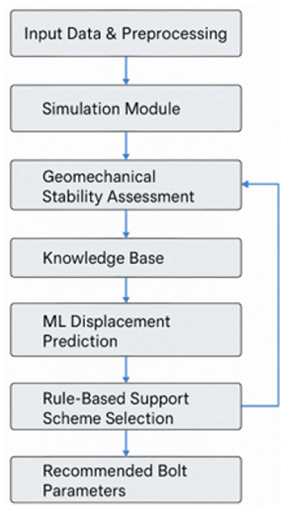
The system comprises six core modules, as illustrated in
Figure 1:
Input Data and Preprocessing Module: This module collects and prepares input data on excavation geometry, rock properties, and mining conditions. This includes the normalization, validation, and integration of data sources;
Simulation Module: This module performs numerical calculations based on geomechanical models to estimate stress conditions and potential failure zones. This component simulates support behavior using models calibrated through Anker2019;
Geomechanical Stability Assessment: This module implements analytical and empirical criteria to determine excavation stability. This includes strength-based thresholds, proximity to failure states, and safety margin evaluations;
Knowledge Base: This module stores structured information, including the physical and mechanical properties of rocks, historical observations, empirical dependencies, and engineering rules for bolt design;
ML-Based Displacement Prediction: This module uses trained machine learning models to forecast roof displacements under specific conditions, enhancing the accuracy of stability forecasting;
Rule-Based Support Selection Module: This module applies logical inference rules to select optimal support schemes (e.g., single-row, combined, or multi-level bolts) based on excavation characteristics and predicted behavior.
Each module performs a dedicated function, ranging from data normalization and geomechanical modeling to displacement prediction and support scheme generation. The knowledge base provides shared access to engineering rules, empirical dependencies, and geotechnical parameters.
The system operates as a unified decision-support platform: input data are first processed and evaluated for completeness and then passed through numerical simulations and machine learning models. Final engineering recommendations are generated through rule-based logic, drawing from the knowledge base. This modular integration supports consistency, scalability, and transparency in design decisions. Its validation is based on simulation and field data from 51 underground excavations in the Karaganda Basin.
The structure and content of the knowledge base are detailed in
Section 2.3, while the logical rules for support selection are discussed in
Section 2.4.
2.3. Design and Structure of the Knowledge Base
The knowledge base serves as the core integrative component of the expert system, ensuring the consistency, interpretability, and repeatability of engineering recommendations. It consolidates input parameters, classification rules, historical observations, and support design logic into a structured and extensible format. As shown in
Figure 1, the knowledge base interacts with all core modules of the expert system and enables consistent information flow between data preprocessing, numerical modeling, and decision logic.
The components of the knowledge base are summarized in
Table 1, which includes key input categories, evaluation logic, support design parameters, and output recommendations.
The knowledge base includes four main layers:
- 1.
The Input Parameters Layer contains standardized input data: excavation geometry, rock strength, moisture coefficient, fracturing intensity, and spatial layout characteristics. These are either directly measured in the field or derived from simulation and corrected using normalization techniques and empirical adjustments.
- 2.
The Calculation Logic and Evaluation Layer formalizes the rules for stability evaluation and support selection. This layer includes the following:
Strength-based thresholds for Ks (support safety factor);
Critical displacement thresholds (Ucrit);
Empirical classification of excavation conditions by combined parameters (e.g., geometry, proximity to adjacent workings, and stress concentration zones).
- 3.
The Support Design Layer stores structured engineering knowledge on rock bolt parameters and design schemes, including the following:
Bolt types (friction bolts, mechanical bolts, cable bolts);
Installation depth and spacing;
Empirical conditions for single-row, two-level, and combined schemes.
- 4.
The Output Layer records final decisions for each evaluated case: selected scheme, calculated safety factor, predicted displacement, and classification result.
The knowledge base is continuously enriched from the simulation results and validated field observations. A total of 51 excavation cases were analyzed to extract dependencies between geotechnical conditions and excavation performance. Special attention was given to the following:
The influence of moisture and fracturing on stability loss;
Conditions where two-level support was required;
Deviation zones where the calculated Ks fell below critical values (e.g., Ks < 1.2).
All input parameters were normalized using Z-score scaling or ordinal encoding (for categorical features). Correction factors were introduced to adjust input values in cases of highly fractured rocks, high moisture, or non-standard excavation geometries. These corrections are embedded in the knowledge base to ensure adequate predictions in complex geomechanical settings.
The logic of support selection based on rule-based inference is detailed in
Section 2.4.
Determination of Physical and Mechanical Properties
To support the development of the expert system’s knowledge base, key rock parameters were selected, including compressive strength, density, internal friction angle, moisture content, and jointing intensity. These values were derived from previously conducted laboratory tests and engineering documentation collected from coal mining operations in the Karaganda Basin. The original test methods followed national standards [
28,
29,
30].
Where necessary, the input data were adjusted to reflect field-specific conditions such as water saturation and structural weakening. The compressive strength Rc was calculated with correction factors for moisture and fracturing, consistent with the computational logic implemented in the Anker2019 simulation platform (see
Section 2.4).
Representative values for major lithotypes (sandstone, siltstone, argillite, and coal) are summarized in
Table 2 and
Table 3.
These parameters were used to normalize input values and to define logic rules for selecting appropriate support schemes within the expert system.
2.4. Integration with Simulation Modules
To support informed and context-sensitive engineering decisions, a numerical simulation module was integrated into the expert system. This module simulates the mechanical behavior of underground excavations under various geological conditions. It is implemented in the Anker2019 software, based on the collapse arch model by M.M. Protodyakonov, and calibrated using data collected from mines in the Karaganda Coal Basin.
The core functions of the simulation module include the following:
Calculating the roof strength (Rc), taking into account layer-by-layer characteristics, moisture content, and jointing;
Estimating the maximum expected roof displacement (Um) based on semi-empirical equations;
Selecting the appropriate support scheme by comparing Rc and Um against engineering safety thresholds.
The design strength of the roof (Rc) is computed using a weighted average of compressive strength by layer, corrected for fracturing and moisture, as follows:
where Rc
i is the compressive strength of the i-th rock layer (MPa); h
i is the thickness of the layer (m);
is the weakening factor due to jointing, and
is the moisture weakening coefficient.
The maximum roof displacement Um is estimated based on excavation geometry, depth, and weakening factors:
where Ut = f(H, Rc) – is the reference displacement corresponding to a standard excavation width of 5 m; Kα, Kw, Kb, and Ka are correction coefficients accounting for cohesion, excavation width, proximity to longwall face, and support type, respectively.
This two-step calculation approach accounts for both the rock strength and the stress state, providing a more accurate representation of excavation stability. The resulting Rc and Um values are transmitted to the logical decision-making module (see
Section 2.5).
A sensitivity assessment of Rc with respect to key coefficients was performed. For example, varying the moisture weakening coefficient k
vl from 0.4 to 0.9 [
31] can reduce Rc by up to 60%, significantly impacting the support choice. For instance, if the original compressive strength is Rc = 25 MPa and k
vl = 0.6, the adjusted design strength becomes Rc = 15 MPa. This corrected value is then used in support selection and stability analysis. Similarly, for jointed rocks with weak interlayers, corrections for depth and structure may affect Rc values by 30–40%. These ranges are supported by field observations and engineering guidelines compiled in the referenced monograph. The expert system’s logic accounts for these parameter fluctuations and triggers stronger support schemes when threshold conditions are approached.
Although the stability coefficient is not directly calculated or displayed in Anker2019, the system applies an equivalent logic.
Comparing Rc and Um enables identification of a transitional stability zone. A value of Ku = 1.1 is used as an engineering benchmark for switching to enhanced support schemes (combined or two-level).
Boundary conditions include the following:
Fixed vertical and horizontal displacements on the bottom boundary;
Fixed horizontal displacements on lateral boundaries;
Stress-controlled top boundary, adjusted for overburden pressure;
Zero-stress (traction-free) condition along the excavation contour.
To confirm numerical stability, a convergence test was performed by refining the mesh from 0.5 m to 0.125 m. The change in displacement values was less than 3%, and the selected support scheme remained the same across resolutions, confirming model robustness.
The calculation sequence includes the following:
Defining excavation geometry (width, height, depth);
Entering geomechanical rock properties (strength, moisture, jointing);
Modeling the load distribution and computing Um;
Passing Rc and Um to the expert system’s logic module (see
Section 2.5).
Correction coefficients for moisture, rock structure, and depth are applied to align the results with real-world underground mining conditions.
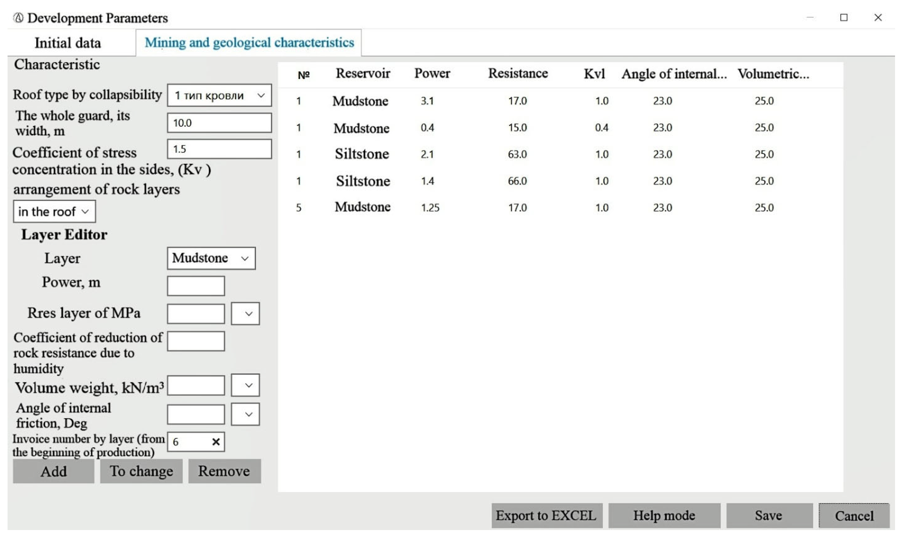
The Anker2019 interface includes the following:
Input panels for excavation and rock parameters;
Support scheme selection;
Result visualization and support recommendations.
This integrated simulation framework ensures adaptability to various geological scenarios and provides a robust foundation for engineering decision making on support design.
In the current system version, a 2D plane strain model is used, as implemented in Anker2019. This approach is suitable for elongated excavations with consistent cross-sections and provides adequate accuracy for engineering calculations. For more complex geometries such as branches, chambers, or changing profiles, a transition to 3D modeling using external platforms, such as RS3, FLAC3D, or BIM/GIS environments is under consideration for future versions of the system.
2.5. Rule-Based Inference Mechanism
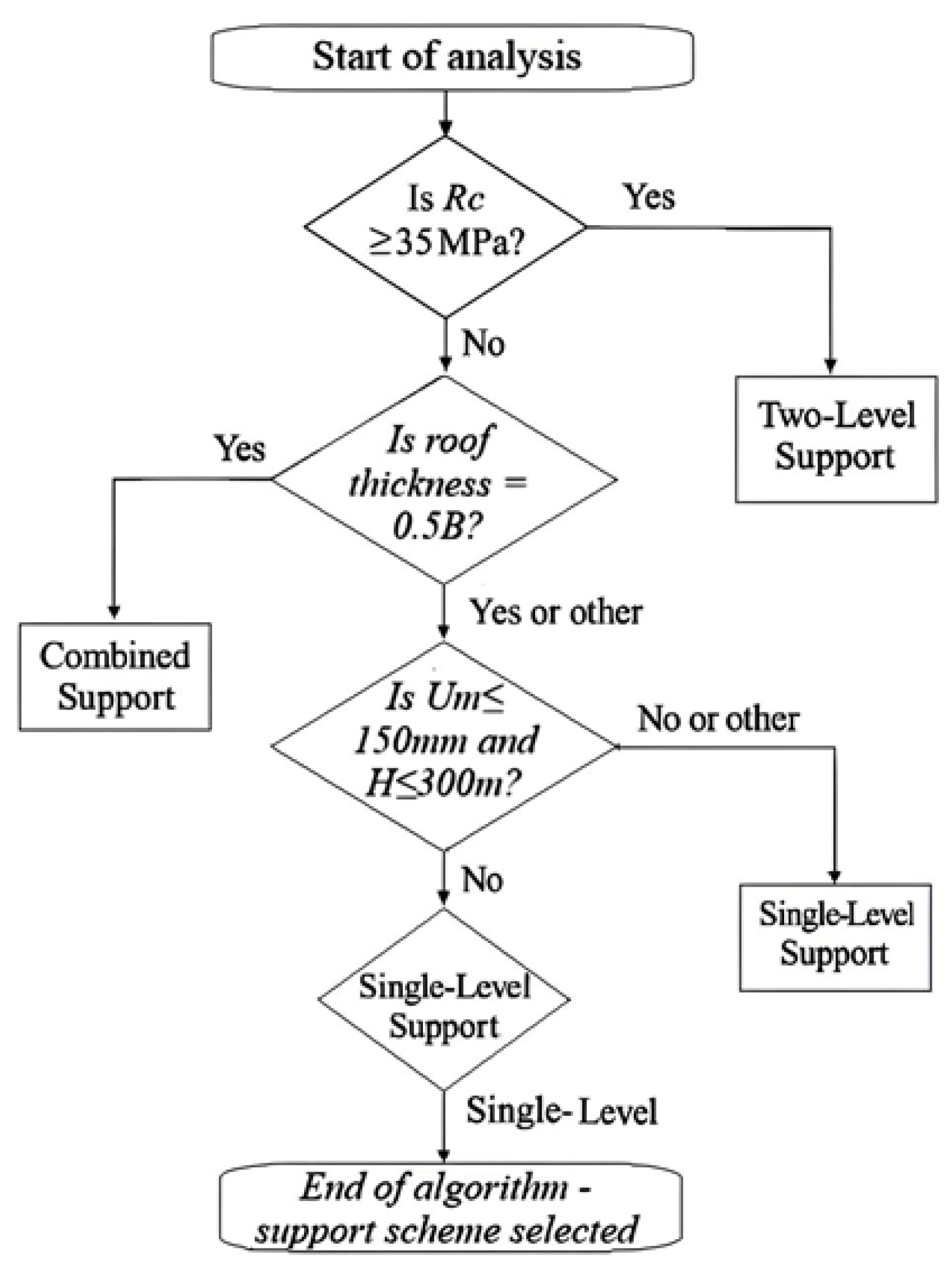
To automate the selection of rock bolt support schemes, the expert system includes a knowledge base structured as a set of formalized logic rules. These rules follow the “If–Then” format and generalize the results of numerical modeling (
Section 2.4), engineering standards, and empirical observations from 51 documented excavation cases in the Karaganda Coal Basin.
Unlike static classification systems such as Q-system or RMR, the proposed logic enables flexible interpretation of input parameters and dynamic adaptation to changing geotechnical conditions.
Although the current version of the system implements a formal rule-based scheme, future versions may incorporate hybrid approaches such as fuzzy logic or decision trees to enhance adaptability. This would be especially useful for applying the system in other mining regions with different geomechanical environments. Methodological guidance for such hybridization combining rule-based expert logic with fuzzy inference is provided in a state-of-the-art review by Madanda et al. [
32].
Each rule consists of the following components:
Condition (IF): A combination of geomechanical parameters derived from simulation, such as roof strength (Rc), expected displacement (Um), excavation depth (H), and so on;
Recommendation (THEN): The proposed support scheme (single-level, combined, or two-level) with parameters such as bolt type, length, and spacing;
Justification: The engineering rationale for selecting the support configuration (see
Table 4).
Examples of Formalized Rules and Conflict Resolution Strategy
A representative subset of expert rules is shown below; the complete rule base is stored within the expert system’s knowledge module.
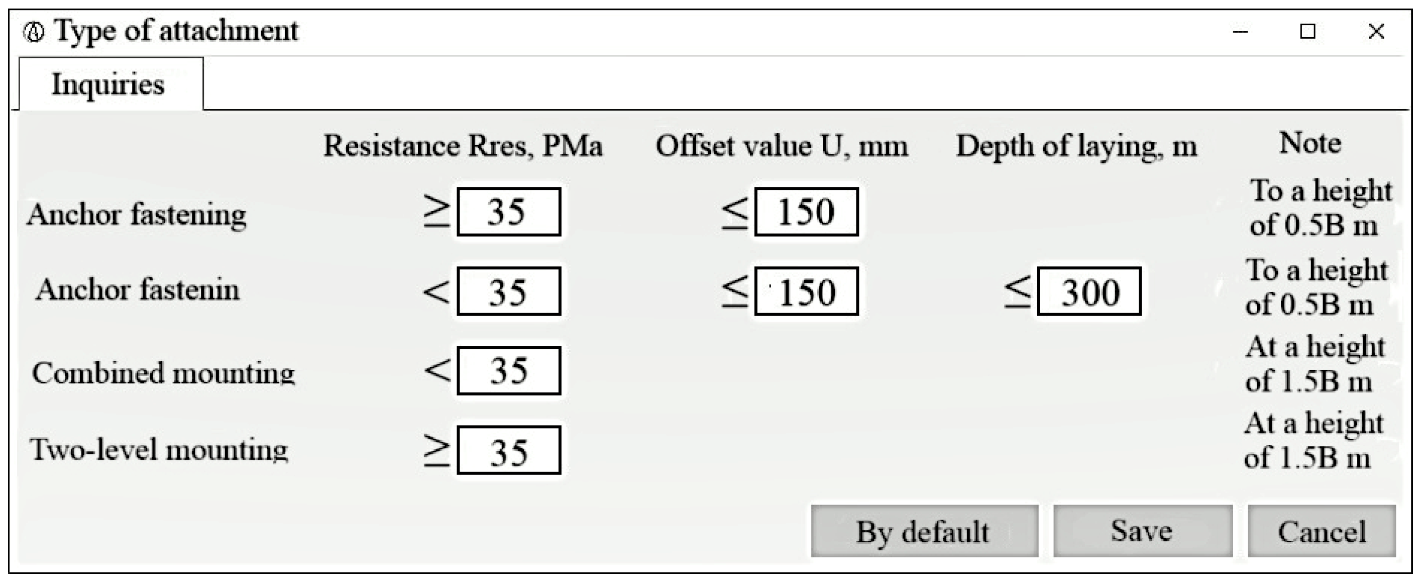
The decision rules shown in
Figure 5 represent the initial logic embedded in the expert system. These rules are not static; they are continuously updated based on the results of numerical simulations and field observations. An example of such an extension, incorporating additional structural and operational parameters, is discussed in
Section 3.3.
The extended list of rules is based on simulation results, expert knowledge, and field data. When multiple rules are triggered, the system applies a prioritization mechanism to select the most reliable support configuration.
If several rules are activated simultaneously, the following hierarchy is applied:
Priority is given to schemes with higher safety margins (two-level > combined > single-level);
Rules derived from simulation data are weighted more heavily than purely empirical ones;
In case of ambiguity, the most conservative option is selected (e.g., two-level support in deep excavations with weak rock).
The inference engine supports both hard triggers (e.g., Rc < 25 MPa) and soft thresholds (e.g., Um in the range of 100–180 mm), ensuring adaptability and compliance with real-world engineering practices.
A screenshot of the rule-based support selection interface in Anker2019 is shown in
Figure 6.
Threshold values for roof strength (Rc), displacement (Um), and excavation depth are used for matching input conditions with support recommendations.
This section presented the architecture of a universal expert system for assessing the stability of underground excavations, based on the integration of numerical modeling, formalized engineering rules, and a structured knowledge base. Key system modules were described, including the numerical models for stability evaluation, the rule-based module for selecting rock bolt support schemes, and the procedures for data normalization and validation. Particular attention was paid to the decision-making logic, which is grounded in real engineering scenarios and calibrated modeling results. The following section presents validation outcomes and representative case studies that demonstrate the practical effectiveness of the proposed methodological approach.
3. Results
This section presents the results of validating the proposed expert system using field data and numerical simulations. The analysis aims to confirm the practical applicability, accuracy, and interpretability of the system’s decision-making logic under real mining conditions.
To achieve this, we evaluated five key aspects:
The consistency between the system’s recommended support schemes and those implemented in the field;
The agreement between simulated and manually calculated values of roof strength and displacement;
The performance of rule-based logic across diverse geological conditions;
The correlation between geomechanical parameters and selected support configurations;
The sensitivity of the system to key input parameters, particularly moisture-related weakening factors.
The results confirm that the expert system reliably reproduces engineering decisions, adapts to input variability, and provides transparent, simulation-calibrated recommendations for support design in underground excavations.
3.1. Validation of Numerical Modeling and Field Observations
The presented case illustrates how the Anker2019 computational algorithms, embedded within the expert system architecture, enable reproducible selection of support schemes and formalize engineering expertise.
Currently, rock bolt support design in the mines of the Karaganda Coal Basin is governed by the “Guidelines for the Calculation and Application of Rock Bolt Support in the Mines of the Karaganda Basin”, developed by the National Scientific Research Center for Industrial Safety and the Directorate of ArcelorMittal Temirtau. Based on the methodology outlined in these guidelines, the Anker2019 software system was developed. It performs calculations as part of one of the modules in the expert system.
Below are the results of support scheme calculations for underground openings in Karaganda mines. The calculations were conducted for working faces monitored under contractual research programs. Both manual calculations and simulations using Anker2019 were performed.
Case Study: Crosscut No. 3 46BK1-z.
The support parameters for crosscut No. 3 46BK1-z were determined based on field conditions (
Table 5) and modeled in Anker2019 (
Figure 7). Key findings include the following:
Excavation depth: 650 m; width: 5.4 m; calculated roof displacement Um = 218.67 mm; roof rock resistance Rc = 22.17 MPa;
Numerical simulation in Anker2019 recommended a combined support scheme, including rock bolts and steel arch supports;
Rock bolt length: 2.6 m; bearing capacity: 100 kN; embedment into stable rock: 0.4 m; exposed length: 0.1 m;
Bolt density: 1.53 units/m2; arch support density: 1.14 frames/m, with a resistance of 290 kN/m.
The results were obtained through both manual and automated support scheme calculations.
The procedure and results of the manual roof displacement calculation are presented in
Table 6.
Since Rc < 35 MPa and the compressive strength was assessed at a roof height of 1.5 B, a combined support scheme was selected in accordance with the methodology derived from regulatory documents and field experience (
Table 7). The results of the validation of the numerical modeling against field observations are summarized in
Table 8.
The following conclusions were reached:
The case demonstrates that the results produced by Anker2019 closely align with manual engineering calculations;
The reliability of the numerical model is confirmed by the match between computed parameters and the actual excavation behavior during operation (no failures or excessive displacements observed);
The use of an automated system standardizes calculations, reduces human error, and ensures the reproducibility of design decisions;
The resulting calculations form the basis for support selection rules integrated into the expert system’s knowledge base, enabling automated and substantiated decision making in support design.
3.2. Rule-Based Logic for Support Selection: Patterns and Examples
This section demonstrates how the rule-based logic for selecting rock bolt support schemes operates under different field conditions and what results are obtained using the Anker2019 simulation system. The aim is to show how formalized dependencies between roof strength, predicted displacements, and excavation depth can be used to make automatic, justifiable decisions on the support type, consistent with engineering practice.
Rule Formalization and Pattern Extraction.
Based on the results of parametric calculations performed in Anker2019 and considering the accumulated experience in applying rock bolt support, the conditions for using single-level, two-level, and combined support schemes were determined. These conditions are adapted to the mining environments of the Karaganda Coal Basin, depending on the excavation depth h, roof rock compressive strength Rc, predicted roof displacement Um, and strength of surrounding rocks (see
Table 4).
Examples of typical decision rules include the following:
If Rc < 25 and Um > 300U_m > 300 mm → two-level support;
If Rc ∈ [25,35] MPa and Um ∈ [150,300] mm → combined support;
If Rc ≥ 35 MPa and Um < 150 mm → single-level support.
The interface used to manage and configure these rules in the expert system is shown in
Figure 5. This interface window, used for configuring rule-based support selection in Anker2019, emphasizes the transparency and interpretability of decision making.
Validation Using Real Excavation Cases.
The values of compressive strength and predicted displacement used for rule validation were derived from real field data processed in Anker2019 (see
Table 9). These values served as inputs for rule-based support selection and were then matched against the expert system’s decision logic.
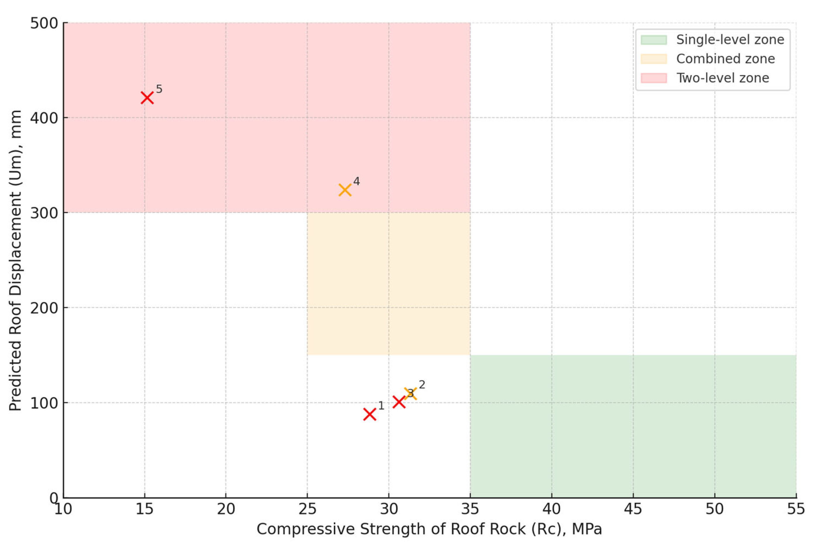
Zoned visualization of the rule-based decision logic embedded in the expert system (
Figure 8). Each color region corresponds to a specific support scheme: green for single-level, orange for combined, and red for two-level rock bolt systems. The numbered dots represent actual excavation cases (see
Table 9) calculated in Anker2019. Their positions confirm the consistency of rule-based logic across a range of compressive strengths (Rc) and predicted displacements (Um).
The correctness of applying the rule-based logic is confirmed in
Table 10, which demonstrates that for all analyzed excavations, the selected support schemes correspond to the predefined conditions and rules implemented in the expert system.
The following conclusions were reached:
3.3. Analytical Relationships Between Rock Mass Conditions and Support Parameters
This section presents the relationships between excavation depth, compressive strength, predicted roof displacements, and the selected support schemes. These relationships were derived from numerical calculations using Anker2019 for representative mine workings in the Karaganda Coal Basin. They form the foundation for the rule-based logic of the expert system and enhance its interpretability under variable rock conditions.
Rock Stability and Support Scheme Selection.
Table 11 presents five real excavation cases, with corresponding depth, predicted roof displacement Um, compressive strength Rc, stability category, and support scheme selected based on the logic described in
Table 4 and implemented in
Figure 5 (interface for configuring rule-based selection in Anker2019).
The applied rules demonstrated full consistency between the actual conditions and the support type assigned by the system logic (
Table 4).
Roof Displacement vs. Excavation Depth.
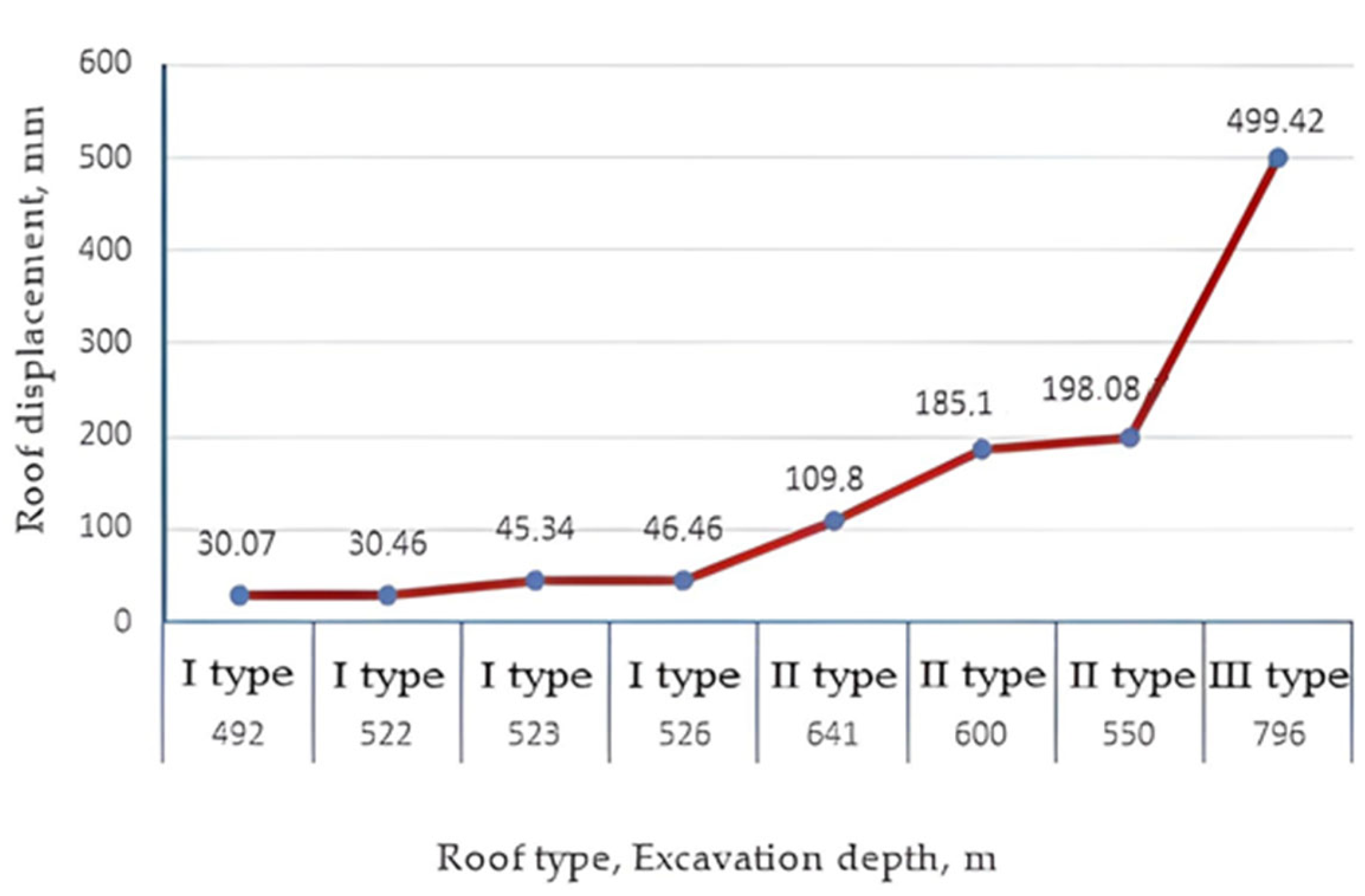
An almost linear relationship was observed between excavation depth and predicted roof displacements. As shown in
Figure 9, an increase in depth from 492 m to 737 m led to a displacement increase from 88 mm to 421 mm. This trend confirms the classification of rock mass conditions based on deformation magnitude.
The corresponding regression equation is as follows:
Anchor Density vs. Strength Parameters.
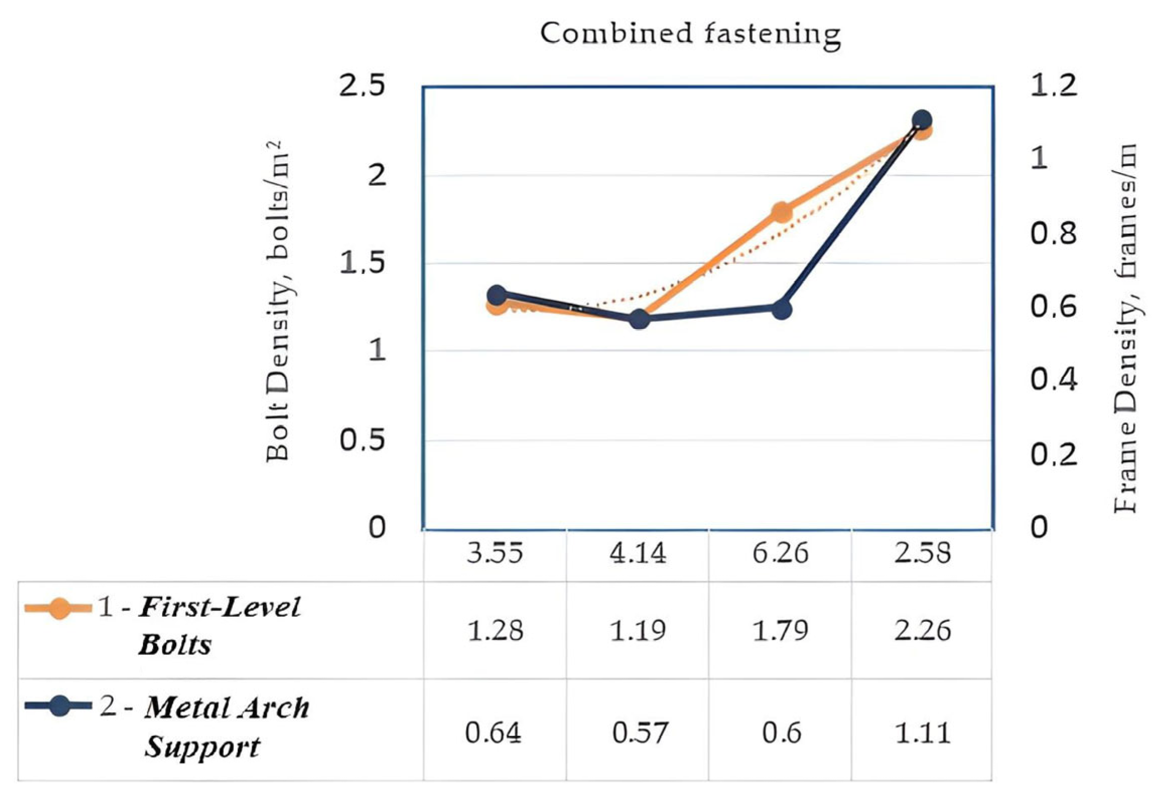
The Rc/Bc ratio (compressive strength to excavation width) demonstrates a strong correlation with the density of anchor bolts in the two-level support scheme. The following quadratic regression describes the relationship observed in
Figure 10:
This relationship confirms the feasibility of using rock mass strength characteristics as predictors for the automated selection of support parameters.
Conclusions: The identified analytical dependencies between rock mass parameters and support design parameters enhance the transparency and justification of the expert system’s decision-making logic. The high accuracy of the regression models (R2 > 0.9) confirms the practical value of these relationships for engineering design decisions under real mining conditions.
3.4. Parameter Sensitivity and Its Role in the Decision Logic of the Expert System
To validate the interpretability and adaptability of the proposed expert system, we conducted a sensitivity analysis of the moisture correction coefficient kv, which significantly influences the compressive strength Rc used in the stability assessment of underground excavations.
The analysis demonstrates how changes in rock mass conditions—particularly moisture content—affect the outcomes of the numerical modeling module and how these outcomes inform the expert system’s rule-based decision logic.
A series of simulations were carried out using Anker2019 software, varying the coefficient k
vl from 0.4 to 0.9. Two lithological layers were examined: argillite (bottom layer, 3 m thick) and aleurolite (middle layer, 10 m thick). All other parameters were kept constant. For each k
vl value, the compressive strength Rc (in MPa) was calculated at a depth of 1.5 B, where B is the excavation width (in meters). The results are shown in
Figure 11.
It can be observed that as the value of k
vl increases, the Rc values also increase, since the coefficient represents the residual strength of the rock relative to its dry state. Formally, it is defined as follows:
where k
vl is the correction coefficient reflecting the reduction in compressive strength due to moisture content in the rock mass; R
c,wet is the compressive strength of the rock at a given moisture level (MPa); R
c,dry is the compressive strength of the same rock under dry conditions (MPa).
The more substantial effect observed in the aleurolite layer is attributed to its greater thickness and corresponding influence on the stress–strain behavior of the excavation roof.
These findings emphasize the importance of calibrating the coefficient kvl based on in situ geological and hydrogeological data. Within the expert system, this parameter is integrated into the logical rules that determine the selection of support schemes.
By accounting for rock mass saturation through kvl, the expert system improves both the accuracy of stability predictions and its flexibility across diverse mining environments. This allows the expert system to generate reliable support recommendations based on simulation-calibrated strength parameters, improving stability assessment under variable geological conditions.
4. Discussion
4.1. Comparison with Existing Methods
At present, the stability of underground excavations is commonly evaluated using either advanced numerical modeling tools such as FLAC3D and RS2 [
33] or empirical rock mass classification systems like RMR, Q-system, and SRMR [
34,
35,
36]. However, each of these methods has notable limitations. Numerical models require extensive geological input and computational resources, which limit their use in routine mine planning. Conversely, empirical systems, while fast and simple, often fail to capture site-specific geomechanical variability, especially in fractured or moisture-sensitive rock masses.
The proposed expert system addresses this gap by combining the numerical modeling of physical parameters, specifically roof compressive strength (Rc) and displacement (Um), with formalized decision logic rooted in engineering practice. Unlike traditional systems, it enables localized support selection calibrated through simulation results and expert-based correction factors, making it adaptable to varying geological and operational conditions.
Moreover, the rule-based logic provides full transparency and interpretability, which is particularly valuable in engineering workflows where reproducibility and regulatory justification are required.
4.2. Advantages of the Proposed Approach
The expert system provides several notable advantages over conventional approaches:
Adaptability: It operates effectively even with incomplete or uncertain input data, thanks to empirically calibrated correction coefficients. This flexibility is especially valuable in operational mining environments, where full geological characterization is often unavailable;
Interpretability: The system relies on transparent rule-based logic, grounded in simulation results and formalized engineering rules. Although no direct field tests were conducted by the authors, the approach reflects established industry practices and parameter ranges. Each decision is explainable and traceable, which facilitates regulatory approval and peer review;
Practical Utility: The system was validated against 51 excavation cases from the Karaganda Coal Basin, showing a high level of agreement with field-tested support decisions. In several cases, it recommended enhanced configurations (e.g., two-level bolting), aligned with conditions of increased deformation or weak rock zones.
These features make the system not only scientifically rigorous but also well suited for routine mine design tasks, particularly where simulation-calibrated values of Rc and Um are available.
4.3. Limitations and Model Sensitivity
Despite its demonstrated effectiveness, the proposed system has limitations that must be acknowledged:
Sensitivity to input parameters: The accuracy of stability predictions depends on the precision of several critical factors, such as fracturing intensity, moisture correction coefficient (kvl), and the presence of weak interlayers. Inaccurate or missing inputs can lead to misclassification of stability conditions or inappropriate support recommendations;
Scope of applicability: The current version of the system is optimized for standard excavation geometries and conditions typical of coal mines. Its application to more complex geological environments (such as non-uniform cross-sections, chambers, or intersecting headings) may require additional calibration or integration with 3D simulation platforms;
Data limitations: In approximately 3% of the cases analyzed, the support scheme recommended by the expert system differed from manual engineering calculations. These discrepancies were primarily caused by incomplete geological input, such as unknown properties of weak interlayers, moisture levels, or excavation context. This emphasizes the need for continued refinement of correction factors and knowledge rules. Validation of the expert system is ongoing, with further adjustments expected as more excavation data become available.
4.4. Practical Value and Future Work
The proposed expert system provides a robust, interpretable, and scalable framework for assessing excavation stability and designing support systems under variable geomechanical conditions. Its modular architecture facilitates integration into digital mine management platforms and lays the foundation for future digital twin systems focused on underground excavation stability. The system can serve as a decision-support tool for both design tasks and operational monitoring.
Planned future developments include the following:
Expansion of the knowledge base by incorporating additional excavation cases from other mining regions with differing geological profiles;
Integration with spatial analytics platforms, including BIM and GIS, to enable three-dimensional visualization and zone-based risk mapping;
Development of diagnostic visualization tools, such as real-time heatmaps based on input parameters, simulation outputs, and excavation geometry;
Implementation of scenario analysis capabilities, allowing engineers to evaluate the impact of varying geological, hydrological, or stress-related conditions on excavation stability and support performance;
Extension of the rule-based engine, potentially incorporating fuzzy logic or hybrid AI frameworks to improve adaptability in uncertain or data-sparse environments.
These enhancements aim to broaden the applicability of the expert system and make it a core component of automated decision-making workflows in smart mining environments.
4.5. Applicability to Other Mining Contexts
While developed for coal mines in the Karaganda Basin, the expert system’s logic based on Rc and Um thresholds is applicable to other mining contexts. Its modular architecture enables site-specific adaptation through recalibration of correction factors and expansion of the knowledge base. This makes the system transferable to ore, salt, and mixed-lithology mines under varying geomechanical conditions.
