1. Introduction
The ultrasonic transducer is a device that converts electrical signals into the required ultrasonic waves, and it is widely used in fields such as ultrasonic cleaning, ultrasonic welding, ultrasonic non-destructive testing, ultrasonic medical imaging, ultrasonic water treatment, underwater acoustic communication, and energy harvesting [
1]. Currently, the most widely used transducers are magnetostrictive transducers and piezoelectric transducers [
2]. Compared with piezoelectric materials, giant magnetostrictive materials (GMMs) exhibit high thermal conductivity, better heat dissipation performance, a larger magnetostriction coefficient, which is 3~5 times that of piezoelectric ceramics, higher energy density, and a lower sound velocity, it also has no overheating failure problem, fast response speed, and strong load capacity. These characteristics determine that GMM is an excellent functional material for the development of high-power, large-amplitude, and wide-frequency ultrasonic machining systems [
3,
4]. The superior dynamic properties of GMM make it suitable for applications in actuators, sensors, vibration energy harvesting, and other fields [
5,
6,
7].
Li et al. [
8] designed a window-type magnetostrictive transducer and conducted simulation analyses on the window-type transducer and the rod-type transducer, respectively, using the finite element method. The window-shaped transducer has less magnetic flux leakage, lower impedance, and its output amplitude is approximately 1.5 times that of the rod-shaped transducer. Wang et al. [
9] carried out simulation calculations on the influence of structural parameters on the vibration performance of window-type giant magnetostrictive transducers in order to obtain the optimal vibration performance of the transducers. To reduce the ineffective energy loss and cool the giant magnetostrictive transducer, Liu et al. [
10] slotted the magnetic cylinder of the transducer axially and investigated the influence of the slot width on the transducer’s performance. Cai et al. [
11] made magnetic conductors using silicon steel, ferrite, and magnetic powder cores, and experimentally studied the influence of these three magnetic conductor materials on the electromechanical conversion efficiency of giant magnetostrictive transducers. Bai et al. [
12] designed a giant magnetostrictive transducer using a multi-rib magnetic circuit, which reduces heat loss and also lowers the mass of the magnetic yoke. Liu et al. [
13] proposed a giant magnetostrictive actuator composed of multi-layer silicon steel. This structure reduces high-frequency eddy current loss in the magnetic circuit components and improves the high-frequency vibration performance of the actuator. Compared with materials such as pure iron and silicon steel, which have high magnetic permeability, GMM has relatively low magnetic permeability. Reasonably arranging magnetic conductive materials with a certain structure outside the excitation coil of the transducer can reduce magnetic flux leakage and improve the vibration performance of the transducer [
14]. Lan et al. [
15] performed slicing treatment on the permanent magnet of the giant magnetostrictive transducer. The transducer after slicing optimization has reduced eddy current loss and can suppress the temperature rise when the transducer works for a long time. Teng et al. proposed a GMM rod with a digital slot structure and estimated the eddy current loss of the rod using finite element software. Compared with an untreated rod of the same size, the eddy current loss of the rod with the digital slot structure is reduced by 78.5% [
16]. Huang et al. [
17] cut Terfenol-D rods into square rings of different shapes, studied the changes in their magnetic energy loss under different frequencies and magnetic flux density amplitudes, and analyzed the influence of material anisotropy on the loss. Li et al. [
18] conducted eddy current simulation analysis on GMM rods with different structures using finite element software. The rods were sliced and slit, respectively, and the vibration performance of the giant magnetostrictive transducers with two structures of GMM rods is studied. Magnetic energy loss can be reduced, and vibration performance improved by cutting the GMM rod [
19]. Gandomzadeh et al. [
20] designed nickel cores of nine different shapes and studied the influence of the shape of the nickel core on its magnetostrictive force, magnetic flux density distribution, and coil voltage by using the finite element method. It is of great significance to study and optimize the magnetic circuit and structure of the giant magnetostrictive transducer to enhance energy conversion efficiency and improve vibration performance.
In this work, based on the equivalent circuit method, the electromechanical equivalent circuit of the giant magnetostrictive transducer is derived. The dynamic simulation calculation of transducers with magnetic blocks of different sizes is carried out using the finite element method. The impedance and output amplitude of the two transducers are tested experimentally, and their vibration performance is studied.
2. Design of the Giant Magnetostrictive Transducer
Figure 1 shows the structure diagram of the giant magnetostrictive transducer. The nodal plane of the transducer is designed at the joint surface between the tail mass and the rear magnetic block, and the magnetic cylinder is fixed on the tail mass through threads to secure the coil, coil skeleton, and magnetic cylinder. The magnetic cylinder and the magnet block form a magnetic circuit outside the coil to reduce the magnetic flux leakage of the transducer. Permanent magnets are set at both ends of the Terfenol-D rod, and the excitation coil generates a high-frequency alternating magnetic field. The Terfenol-D rod will generate ultrasonic vibration under the alternating magnetic field [
14]. The head mass radiates the ultrasonic vibration energy generated by the Terfenol-D rod, and the tail mass reduces the radiation of ultrasonic vibration energy. Bolts and nuts connect the various parts of the transducer.
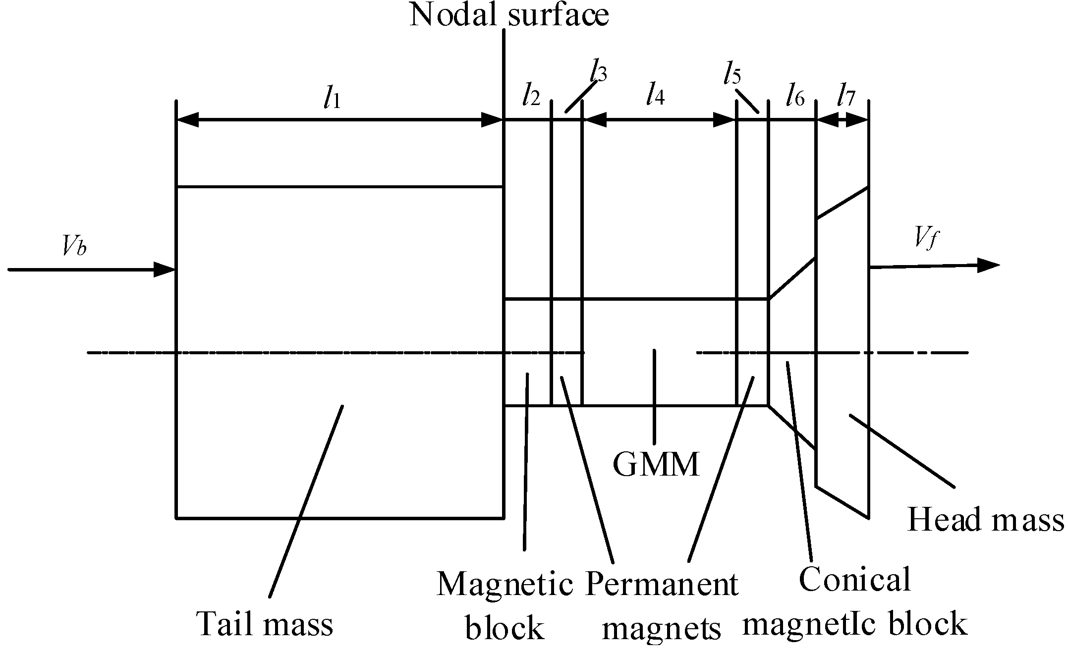
Figure 2 shows the size diagram of the giant magnetostrictive transducer. The transducer is simplified into the tail mass, the magnetic block, the permanent magnet, the GMM, and the head mass, ignoring the bolt and nut; the length of the tail mass is
l1, the diameter is
D1, and the magnet block, permanent magnet, and GMM rod have the same diameter. The permanent magnets at both ends of the GMM rod have the same dimensions.
According to reference [
21], the electromechanical equivalent circuit of the giant magnetostrictive transducer in this paper is derived, as shown in
Figure 3.
Where, as seen in
Figure 3,
is the electromechanical conversion coefficient,
ω = 2
πf is the angular frequency,
Rc is the static resistance,
lc is the static inductance of the coil,
N is the number of turns of the coil,
,
g33 is the piezomagnetic constant,
d33 is the magnetostrictive strain constant,
is the permeability under constant stress, and
is the compliance coefficient.
The impedance of the uniform cross-section part in the transducer is
where
ln,
ρn,
cn,
sn, and
kn are the length, density, sound velocity, cross-sectional area, and wave number of the
n-th section of the transducer, respectively.
The impedance of the conical magnet block and head mass is
where
lm,
ρm,
cm,
sm, and
km are the length, density, sound velocity, cross-sectional area, and wave number of the
m-th of the transducer, respectively.
sm1 and
sm2 are the cross-sectional areas behind and in front of the conical magnetic block and the head mass, respectively.
If the load of the transducer is not considered,
Zb =
Zf = 0, and the input impedance of the transducer can be obtained from the electromechanical equivalent circuit diagram as follows:
where
is the mechanical impedance,
is the electrical impedance.
, , , , , , , .
The large mechanical quality factor indicates that the transducer has a larger amplitude and higher efficiency, and the mechanical quality factor of the transducer can be expressed as follows:
where
fr is the resonance frequency,
fa is the anti-resonance frequency,
Za is the maximum impedance, and
Zr is the minimum impedance.
By setting
Zi = 0 in Equation (6), the frequency equation of the giant magnetostrictive transducer can be obtained. The nodal plane of the transducer is located at the joint surface of the rear magnetic block and the tail mass, so the length of the tail mass is one-quarter wavelength.
Table 1 shows the material parameters of the transducer [
14].
According to the frequency equation and the material parameters, the dimensions of the transducer is calculated. The dimensions of the transducer are as follows:
l1 = 62.5 mm, l2 =6 mm, l3 = 3 mm, l4 = 20 mm, l5 = 3 mm, l6 = 5 mm, l7 = 7 mm; D1 = 62 mm, D2 = D3 = D4 = D5 = 20 mm, d6 = 20 mm(conical magnetic block small end diameter), D6 = 28 mm(Conical magnetic block large end diameter), d7 = 50 mm(horn small end diameter), D7 = 62 mm(horn large end diameter).
Based on Equations (6) and (7), Mathematica 12.0 (Wolfram Research) is used to calculate the resonance frequencies and mechanical quality factor of the two transducers, the resonant frequency of the transducer with a cylindrical magnetic block is 20.084 kHz, and its mechanical quality factor is 61, while the resonant frequency of the transducer with a conical magnetic conductor is 20.836 kHz and its mechanical quality factor is 199.
3. Finite Element Calculation
The solid mechanics and magnetic field are selected, and the giant magnetostrictive transducer model is established in COMSOL Multiphysics 5.4 AC/DC module (COMSOL Inc., Stockholm, Sweden). In order to reduce the simulation calculation time, the influence of the bolt and nut on the calculation results of the transducer is ignored, which has little effect on the calculation results after simplification [
14]. According to reference [
22], the piezoelectric constant matrix, relative magnetic permeability matrix, and elastic constant matrix of the GMM are obtained. The relative permeability of air is 1, and the conductivity of air is set to 1 to improve the convergence of the simulation calculation. The conductivity of copper is 6 × 10
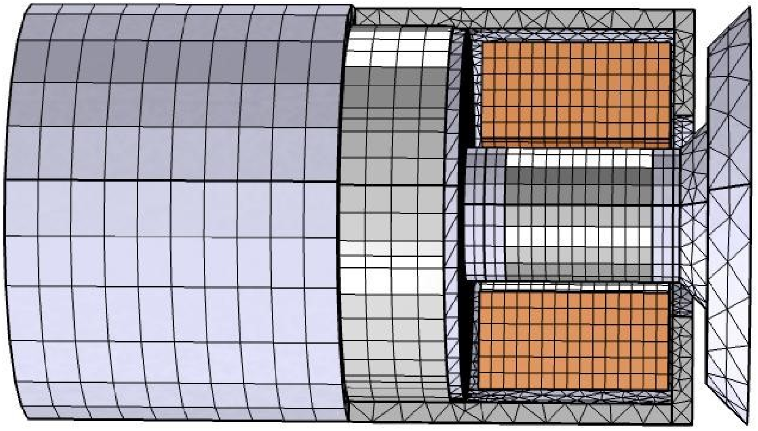
7 S/m, and the relative permeability of copper is 1. The number of turns of the coil is 350, the wire model is set as homogenized multiple-turns, the coil type is set as numeric, and the excitation voltage is 200 V. The magnetostrictive model is set as linear element, constitutive relationship is set as stress-magnetization form. The large end diameter of the conical magnetic block is 28 mm, and the small end diameter is 20 mm. First, mesh each part of the transducer, and then mesh the air domain outside the transducer. Taking the transducer with conical magnetic block as an example, the total number of nodes and volume meshes are 17,101 and 63,490, respectively, and the air domain outside the transducer is not displayed.
Figure 4 shows the grid diagram of the transducer of a conical magnetic block. The Stationary Solver is used to solve the calculations, the default relative tolerance is set to 0.001, and when the relative error of the calculated result is less than or equal to the set relative tolerance, it is considered to have reached the convergence condition and the calculation is stopped.
Eigenfrequency analysis is performed in COMSOL Multiphysics.
Figure 5 shows the vibration mode of two transducers. It can be seen from the figure that the amplitude of the output end of the head mass of the two transducers is the largest, and the amplitude of the tail mass is the smallest. The resonant frequency of the transducer with a conical magnetic block is greater than that of the transducer with a cylindrical magnetic block.
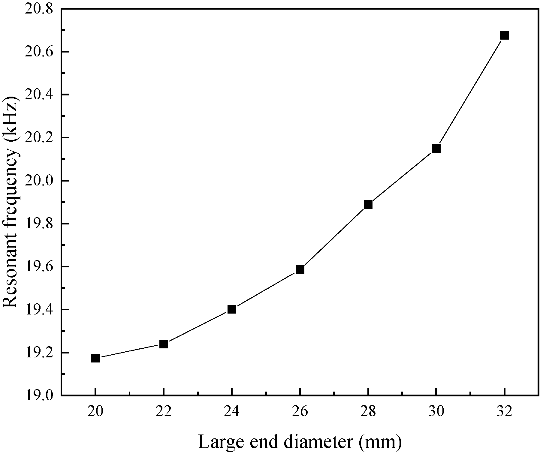
Figure 6 shows the resonant frequencies of transducers with conical magnetic blocks of different large end diameters. As can be seen from the figure, the larger the diameter of the large end of the conical magnetic block, the higher the resonant frequency of the transducer.
Frequency domain analysis is performed at the resonant frequencies of the transducers.
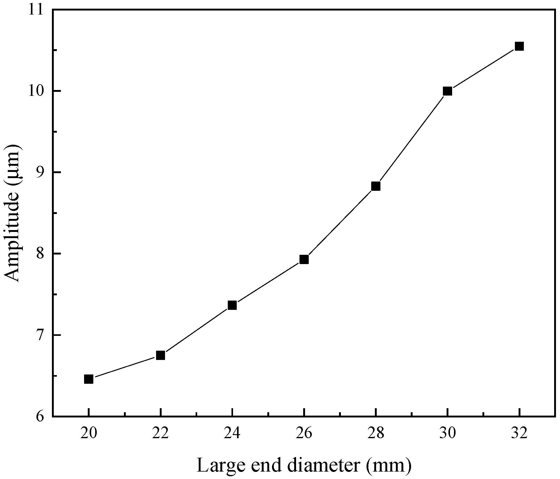
Figure 7 shows the relationship curve between conical magnetic blocks with different large end diameters and the output amplitude of the transducer. The larger the diameter of the large end of the conical magnetic block, the greater the output amplitude of the transducer.
The mechanical quality factor of the transducers with a cylindrical magnetic block obtained by simulation calculation is 66; the large end diameter of the conical magnetic block is 28 mm, and the mechanical quality factor of the transducer with a conical magnetic block is 106.
The stress distribution diagrams of the two transducers are shown in
Figure 8. It can be seen from the figure that the stress on the magnetic block and the permanent magnet in contact with the tail mass in the transducer with a cylindrical magnetic block is the largest, while the stress on the contact part between the cylindrical magnetic block and the head mass is slightly smaller. In the transducer with a conical magnetic block, the stress at the contact part between the conical magnetic block and the head mass is the largest, while the stress on the magnetic block and the permanent magnet in contact with the tail mass is slightly smaller; the maximum stress of the transducer with a conical magnetic block is greater than that of the transducer with a cylindrical magnetic block.
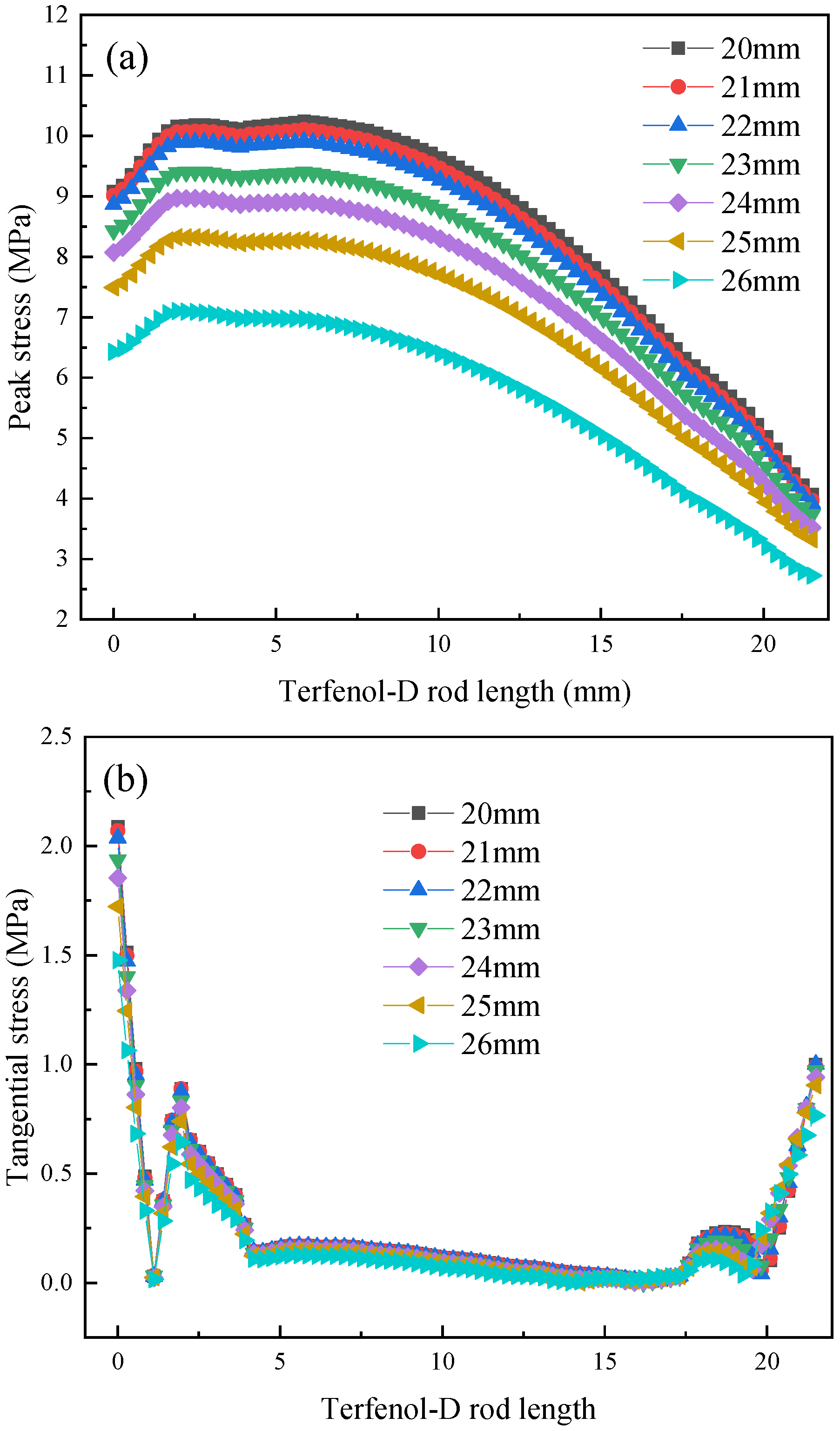
The peak and tangential stress distributions of Terfenol-D rods are obtained in the 1D plot group of the results in COMSOL Multiphysics.
Figure 9 shows the relationship curve between conical magnetic blocks with different the large end diameters and the stress distribution of Terfenol-D rods. It can be seen from the figure that as the diameter of the large end of the magnetic block increases, the peak stress and tangential stress of the rod decrease; the peak stress of the rod is smaller at both ends and larger in the middle, and the peak stress of the rod close to the tail mass is greater than that at end close to the head mass; and the tangential stress of the rod is greater at both ends and smaller in the middle, and the tangential stress at the end close to the tail mass is relatively larger. This is because under high-frequency magnetic fields, the magnetic field distribution inside the Terfenol-D rod is very complex. The Terfenol-D rod not only has longitudinal strain, but also a certain lateral strain, resulting in a complex axial stress distribution of the rod.
4. Experimental Test
According to the finite element calculation results, the larger the diameter of the large end of the magnetic block, the higher the resonant frequency and output amplitude of the transducer, and the smaller the stress. The design frequency of the transducer is 20 kHz; therefore, the large end diameter of the magnetic block is selected as 28 mm.
Figure 10 shows the manufactured cylindrical magnetic block and conical magnetic block. The impedance analyzer (4294A, Agilent, Santa Clara, CA, USA) measures the impedance of two transducers.
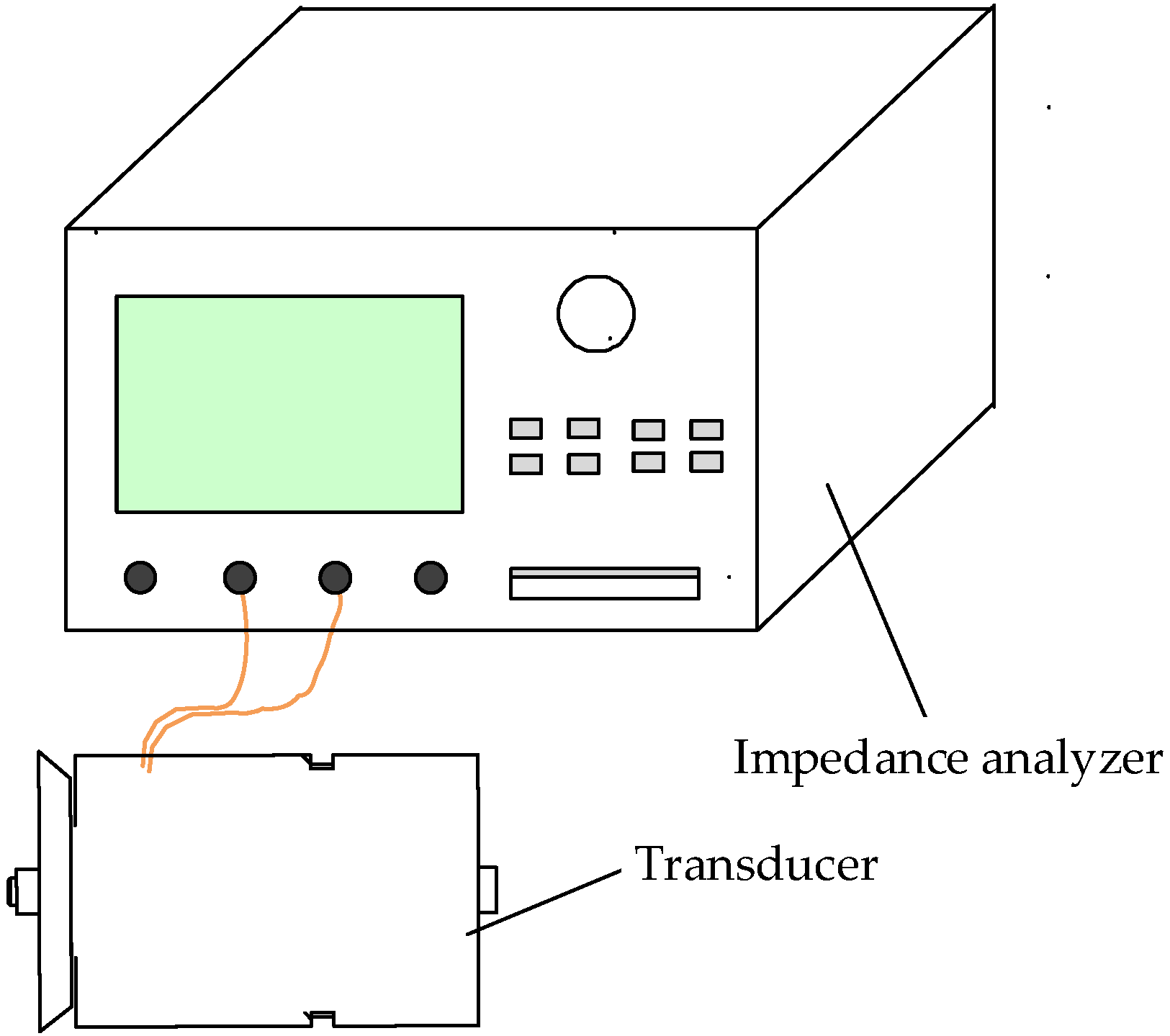
Figure 11 shows a schematic diagram of the impedance test of the transducer. The impedance curves of the two transducers are shown in
Figure 12.
The mechanical quality factor of the transducer is the following:
where
fs is the resonant frequency,
f1 and
f2 are the half-power frequencies.
Table 2 shows the impedance test results of the two giant magnetostrictive transducers. The experimental test results show that the resonant frequency of the transducer with a cylindrical magnetic block is 19.520 kHz and its mechanical quality factor is 54, while the resonant frequency of the transducer with a conical magnetic block is 19.632 kHz, and its mechanical quality factor is 160. The resonant frequency and mechanical quality factor of the transducer with a conical magnetic block are greater than those of the transducer with a cylindrical magnetic block, and it also indicates that changing the cylindrical magnetic block to a conical one can better improve the working efficiency of the transducer.
A high-speed bipolar power supply (BP4620, NF, Yokohama, Japan) is used to output high-frequency electrical signals, and the output amplitude at the end face of the head mass of the transducer is measured using a laser vibrometer (LV-S01, Sunny Optical, Ningbo, China); a dynamometer (WT1600, Yokogawa, Yokohama, Japan) is used to measure the power of the transducer, and an adjustable capacitor box (RX7-9N8B, Shanghai Ningfang, Shanghai, China) is used to match the impedance of the transducer.
Figure 13 shows the experimental test diagram of the two transducers.
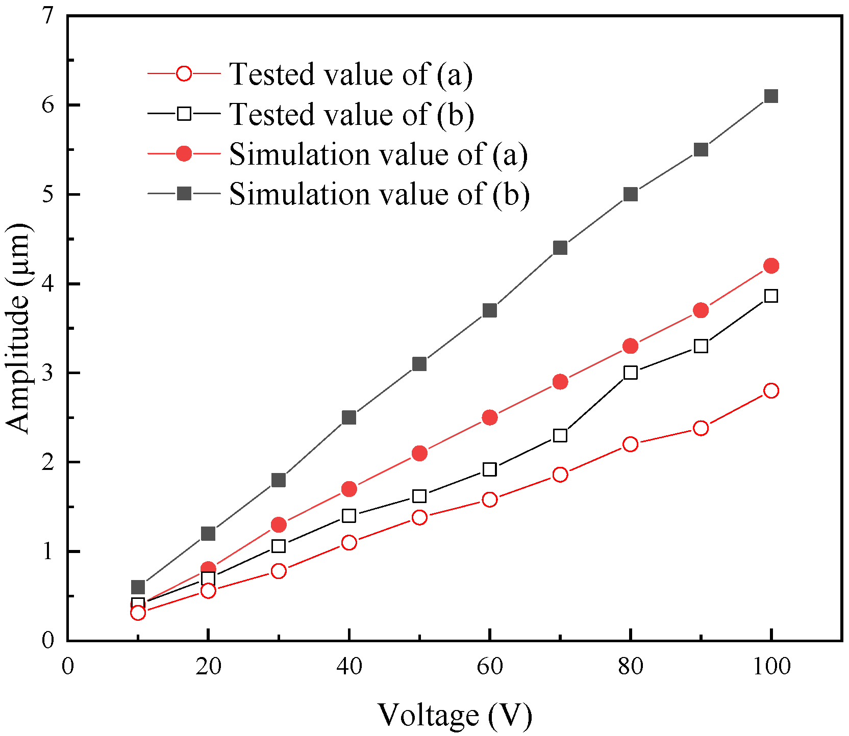
Figure 14 shows the output amplitudes of the two transducers under different voltages. It can be seen from the figure that as the excitation voltage increases, the output amplitudes of both transducers increase; the output amplitude of the transducer with a conical magnetic block is greater than that of the transducer with a cylindrical magnetic block. This paper mainly considers the specific shape of the magnetic block. The magnetic block in the transducer is cylindrical, compared with the diameter of the head mass, the diameter of the cylindrical magnetic block is smaller, and the ultrasonic vibration energy generated by the Terfenol-D rod cannot be effectively radiated from the head mass, resulting in greater stress near the rear magnetic block and permanent magnet. After replacing the cylindrical magnetic block with a conical one, the transverse size of the magnetic block increases, which is more conducive to the radiation of ultrasonic vibration energy generated by the Terfenol-D rod to the head mass, the output amplitude and mechanical quality factor of the transducer increase, the maximum stress at the contact part between the conical magnetic block and the head mass also increases, while the stress on the magnetic block and the permanent magnet decreases. There is a certain error between the simulation value and the test value of the output amplitude of the two transducers, because the simulation calculation does not consider damping, resulting in a large calculation result. The resonant frequencies and output amplitudes of the two transducers obtained from experimental tests are basically consistent with the results of the simulation calculations.
5. Conclusions
In this paper, based on the one-dimensional longitudinal vibration theory, the electromechanical equivalent circuit of the giant magnetostrictive transducer is derived. Simulation calculations and experimental tests are carried out on transducers with conical magnetic blocks of different sizes, and the following conclusions are obtained:
(1) The larger the diameter of the large end of the conical magnetic block, the greater the output amplitude and resonant frequency of the transducer, and the smaller the peak stress and tangential stress of the Terfenol-D rod; the peak stress and tangential stress at the end of the rod close to the tail mass are greater than those at the end close to the head mass, and the peak stress of the rod is smaller at both ends and larger in the middle, while the tangential stress of the rod is larger at both ends and smaller in the middle.
(2) The resonant frequency of the transducer with a cylindrical magnetic block obtained from experimental tests is 19.520 kHz and its mechanical quality factor is 54; the resonant frequency of the transducer with a conical magnetic block is 19.632 kHz and its mechanical quality factor is 160. The resonant frequency, output amplitude, stress, and mechanical quality factor of the transducer with a conical magnetic block are greater than those of the transducer with a cylindrical magnetic block. The resonance frequencies, mechanical quality factors, and output amplitudes of the two transducers obtained from experimental tests are basically consistent with the calculation results. This research optimized the structure of the magnetostrictive transducer and improved its vibration performance.

