Abstract
To address the adverse effects of Tuned Inertia Dampers (TIDs) on track slab vibrations while controlling high-frequency rail vibrations, a hybrid Finite Element-Statistical Energy Analysis (FE-SEA) method is developed for modeling the vehicle-track-bridge coupled system. Short-wavelength track irregularities are introduced as high-frequency excitation, and the accuracy and efficiency of this method are validated by comparison with the traditional finite element method (FEM). A vibration control model for track-bridge structures incorporating TIDs is designed, and the effects of the TID’s inertance, stiffness, and damping coefficients on the vertical acceleration responses of the rail and track slab are investigated in detail. The study reveals that although TIDs effectively reduce rail vibrations, they may induce adverse effects on track slab vibrations. Using the vibration acceleration amplitudes of both the rail and track slab as dual control objectives, a multi-objective optimization model is established, and the TID’s optimal parameters are determined using a multi-objective genetic algorithm. The results show that the optimized TID parameters reduce rail acceleration amplitudes by 16.43% and improve the control efficiency by 12.45%, while also addressing the negative effects on track slab vibration. The track slab’s vibration acceleration is reduced by 5.47%, and the vertical displacement and acceleration of the vehicle body are reduced by 14.22% and 47.5%, respectively, thereby enhancing passenger comfort. This study provides new insights and theoretical guidance for vibration control analysis in vehicle-track-bridge coupled systems.
1. Introduction
With the rapid development of high-speed railways and track-bridge infrastructure in China, train speeds have significantly increased. However, higher operating speeds tend to induce intense vibrations in track-bridge structures, which can threaten operational safety and reduce ride comfort. Therefore, the analysis and control of vibration in railway structures are of critical engineering significance.
In the study of vibration control for track-bridge systems, dynamic response analysis is a fundamental step. Common numerical simulation methods include the FEM and Statistical Energy Analysis (SEA). Since the rail structure exhibits high-frequency vibrations and satisfies SEA assumptions, SEA is often preferred for its computational efficiency. However, applying FEM to such high-frequency scenarios results in a dense modal spectrum and a high number of degrees of freedom, making the equations difficult to solve. Conversely, bridge structures, which typically exhibit low-frequency vibrations, are more accurately analyzed using FEM. Neither method alone is sufficient for comprehensive modeling of systems. To overcome this limitation, Langley et al. [1,2] proposed a hybrid FE-SEA method based on modal superposition and fuzzy structural theory, which enables full-frequency analysis of complex structural responses. Luo et al. [3] applied the FE-SEA method to simulate a four-layer track-bridge structure, simplifying the vehicle model to four independent wheelsets with vertical motion, and analyzed vertical dynamic responses under random irregularities. Lei et al. [4] used a hybrid model to study the noise characteristics of box girders and validated the results against experimental data. These studies confirm the applicability and accuracy of the FE-SEA method in analyzing railway structure vibrations, as well as its high efficiency, laying a solid foundation for vibration control investigations in such systems. Additionally, Sheng et al. [5] investigated the influence of overall ballast track fastening stiffness on the vertical vibration and sound power characteristics of rails using the spectral element method, while Gao et al. [6] employed the 2.5D finite element method to study unsaturated ground vibrations induced by high-speed train loads. These wave-based models offer clear advantages in the analysis of high-frequency responses in track structures. In contrast, the hybrid FE–SEA method, benefiting from its simplicity in modeling and high computational efficiency, holds a significant position in time-domain vibration response analysis of track systems and serves as an effective and convenient computational platform for the multi-objective optimization conducted in this study.
Vibration control strategies for track-bridge structures include structural parameter optimization and integration of vibration mitigation devices such as Tuned Mass Dampers (TMDs) and inerters. Quan et al. [7] explored the seismic damping mechanism and performance of CRTS III slab ballastless track on an isolation system extradosed cable-stayed bridge during rare earthquakes, while Zhang et al. [8,9] experimentally studied TMD configurations in box girders. In recent years, inerter-based systems have gained attention for their structural simplicity, adaptability, and low maintenance. Studies have examined their effectiveness in vibration control across mechanical, automotive, and civil engineering applications [10,11,12,13,14]. Yang et al. [15] analyzed the vertical dynamic performance of curved tracks using various dampers, finding that TID and AM-TMD outperform conventional TMD. Zhang et al. [16] developed an Inerter-Enhanced Dynamic Vibration Absorber (IDVA) for floating slab tracks, which reduced relative displacements by over 50%. Sheng et al. [17] applied TIDs to floating slab tracks and performed multi-objective optimization, showing improved performance in the 4–16 Hz range. Wei et al. [18] employed a Tuned Viscous Mass Damper (TVMD) to enhance the low-frequency vibration isolation performance of floating slab track systems. By integrating TVMD elements into the vehicle–track coupled system, the method not only preserved the vibration attenuation performance in the medium- and high-frequency ranges, but also effectively broadened the isolation bandwidth and significantly reduced the acceleration levels within the 2–8 Hz frequency range. Numerous studies have shown that inerters with properly tuned parameters can effectively reduce vibrations across different frequency ranges in track structures. However, most of these investigations primarily concentrate on the vibration control performance of the superstructure, overlooking the potential impact of inerters on the underlying substructure. Chen et al. [19] observed that when applied in vehicle suspension systems, inerters exhibit a frequency-dependent behavior characterized by “attenuating low-frequency vibrations while transmitting high-frequency ones.” Consequently, when the track structure is subjected to high-frequency excitations, the use of inerters to suppress vibrations in the rail may inadvertently amplify vibrations in the underlying components, such as the track slab and bridge, thereby accelerating their degradation and reducing their service life.
To address this research gap, the present study establishes a hybrid FE–SEA model of a vehicle–track–bridge system. Short-wavelength irregularities (0.01–1 m) are introduced as high-frequency input to simulate realistic excitation conditions. The dynamic responses of the rail and track slab are computed for a train traveling at 80 m/s. TIDs are installed between the rail and slab, and the influence of their parameters—inertance, stiffness, and damping—on the system’s vertical acceleration, RMS value, and stabilization time is investigated. The study also reveals the adverse effects of TIDs on track slab vibration. Finally, a multi-objective optimization model is constructed, taking the vertical acceleration amplitudes of the rail and slab as dual control objectives. The optimal TID parameters are determined using a multi-objective genetic algorithm (MOGA). The proposed framework aims to achieve simultaneous vibration suppression across structural layers, providing practical guidance for the design and application of TIDs in railway vibration control.
2. FE–SEA Hybrid Model for Bending Vibration of a Simply Supported Beam
2.1. Formulation of the Dynamic Equation
Consider a simply supported beam structure with a uniform cross-section subjected to a vertical load, as shown in Figure 1. The beam is discretized into multiple-node beam elements, as shown in the figure. Let be the length of the beam, the cross-sectional area, the flexural rigidity, and the density. Vertical point load is applied at position along the beam.

Figure 1.
Beam bending vibration element.
In the finite element method (FEM), the shape function matrix for the beam element is defined as
For modal superposition, the vibration mode function for the nth mode of the simply supported beam is expressed as
For Combining these two, the shape function vector is defined as
The nodal displacement vector is denoted as
where represent the vertical displacements and rotational angles at the two ends of the beam. The term refers to the modal amplitude of the nth mode and represents the displacement of the nth virtual node, which is a non-physical node. These virtual displacements are treated in the same manner as actual nodal displacements, where .
Accordingly, the displacement of the beam at any position can be expressed as
The displacement vector satisfies the dynamic equilibrium equation:
where , , and are the mass, damping, and stiffness matrices of the structure, respectively, and is the excitation force vector applied to the structure.
Applying the Fourier transform to Equation (6) yields
where is the dynamic stiffness matrix of the structure and is the angular frequency.
In the mid-to-high frequency range, due to the high modal density, a large number of mode shapes are required to accurately capture the structural vibration response. For analytical convenience, the modal basis is decomposed into two parts and discussed separately. According to the excitation frequency and computational constraints, the structural modes are categorized into global modes and local modes. The shape functions are accordingly divided into global and local components. Assume that mode shapes belong to the global modes. Let the total number of modes be , where and represent the number of global and local modes, respectively. Denoting the corresponding shape functions and , Equation (5) can be rewritten
Here, superscripts and represent the global and local modal components, respectively.
Similarly, Equation (7) can be reformulated in matrix form
By expanding and simplifying, the coupled equations can be expressed
Equations (10) and (11) correspond to the global and local motion equations, which are solved using the FEM and Statistical Energy Analysis (SEA), respectively.
First, the element-level mass, stiffness, and generalized force matrices are computed. According to the finite element formulation, these are expressed
Assuming the structure exhibits Rayleigh damping, the damping matrix is defined as a linear combination of the mass and stiffness matrices:
where and are the Rayleigh damping coefficients.
2.2. Solution of the Global Dynamic Equation
The solution of the global motion equation primarily involves determining two correction terms in Equations (10) and (11): the dynamic stiffness correction term, denoted as , and the generalized force correction term, denoted as . The solution process follows the same principles as the conventional finite element method (FEM).
Assuming the structure contains only a single subsystem, it can be derived that [3]
where is the excitation frequency, and are the natural frequency and damping loss factor of the jth local mode, respectively, and i is the imaginary unit. It can be seen from the above expressions that the correction terms essentially represent the influence of local modes on the global modes. To facilitate time-domain response analysis, the common term in Equations (16) and (17) can be approximated based on the relationship between excitation and local modal frequencies:
- Resonant case ():
When the excitation frequency matches the natural frequency of a local mode, Equation (16) simplifies to
where v is the modal density of the subsystem (defined as the number of modes per unit frequency bandwidth). Equation (18) shows that resonant local modes increase the damping of the global system.
- Non-resonant case ():
In this case, Equation (10) can be approximated
which implies that non-resonant local modes primarily affect the effective mass of the global system.
For local modes with natural frequencies higher than the excitation frequency, their influence on the global motion is neglected. Only the input power from global modes to local modes is considered in the analysis.
Finally, based on the excitation frequency, Equations (12) and (14) are substituted into Equations (18), (19) and (17), respectively, to obtain all required correction terms. The resulting corrected mass matrix, damping matrix, and generalized force vector are then substituted into the governing dynamic equation (Equation (6)) to compute the nodal displacements, velocities, and accelerations. Using Equation (5), the displacement, velocity, and acceleration responses at any location along the beam can be accurately reconstructed.
3. Analysis of Vertical Vibrations in Track-Bridge Structures Under Short-Wavelength Irregularities
3.1. Model of the Vehicle-Ballastless Track-Bridge Vertical Coupled System
In this section, a numerical model of a vehicle with a ballastless track-bridge coupled system is established using the FE–SEA hybrid method. The upper vehicle is represented by a 10-degree-of-freedom vertical model, including the car body (mass and rotational inertia ), bogies (mass and inertia ), and wheels (mass ). Nonlinear Hertzian contact is used to couple the vehicle and track structures. The lower part comprises a CRTS II-type ballastless track structure and a simply supported bridge, modeled as a four-layer Euler Bernoulli beam system with eight nodes per layer: rail, track slab, base layer, and bridge. Each layer shares the same total length. The bridge is composed of five spans supported by piers, as shown in Figure 2.
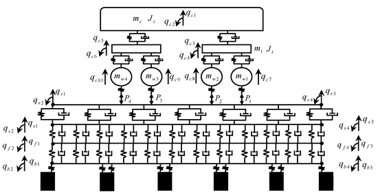
Figure 2.
Vehicle plate track–bridge model.
The subscripts , , , , and denote vehicle, rail, slab, base, and bridge, respectively. Real nodes are used at boundaries, while internal nodes are treated as virtual. Each layer’s degrees of freedom (DOFs) are assigned accordingly. The global displacement vector is defined , and interpolation functions are introduced for each element to construct the system matrices.
The nodal displacement vector is defined
The shape function corresponding to the element is defined
The vehicle’s mass, stiffness, and damping matrices are obtained from the literature [17] and denoted as , , and . According to the FEM, the mass, damping, and stiffness matrices of the track–bridge structure can be systematically derived.
The total mass matrix of the model is expressed
where , , , and represent the mass matrices of the rail, slab, base, and bridge, respectively, derived from FEM expressions (Equation (12)).
The total stiffness matrix is defined as
Here, , , , and denote the stiffness matrices corresponding to the bending strain energy of the rail, track slab, base layer, and bridge, respectively, while , , , and represent the stiffness matrices generated by the discrete elastic support of the rail fasteners (first layer), continuous elastic support of the base CA mortar layer (second layer), continuous elastic support of the bridge (third layer), and discrete elastic support of the bridge piers, respectively. Among them, , , , and can be obtained using Equation (13). Assuming that the system contains fasteners with spacing , where the first fastener is located at the origin of the element and the ith fastener is located at position , the stiffness matrix generated by the first-layer discrete elastic support is given as
where is the stiffness of the rail fastener, and is the shape function vector coupling the rail and track slab, which is defined as
Similarly, the stiffness matrix generated by the discrete elastic support of bridge piers () can be derived.
The stiffness matrix for the second-layer continuous elastic support is given as
where is the elastic coefficient of the CA mortar layer, and is the shape function vector coupling the track slab and base, which is defined as
Likewise, the stiffness of the third-layer continuous elastic support () can be derived accordingly.
The total damping matrix of the model is expressed as
In these expressions, , , , and denote the Rayleigh damping matrices of the rail, track slab, base, and bridge, respectively. , are the Rayleigh damping coefficients for the rail, and likewise , and , are the coefficients for the track slab and base, respectively. , , represent the damping matrices generated by the first-layer discrete elastic support and the second and third layers of continuous elastic support. Their forms are the same as those of , , and , except that , , and are replaced by (rail fastener damping coefficient), (CA mortar damping coefficient), and (bridge damping coefficient), respectively.
Since the loads in the vehicle–track coupled system are moving loads, the position of the jth wheelset at time t is defined as
where is the initial position of the ith wheelset and is the train speed.
According to Equation (14), the generalized force vector for the element can be expressed as
where is the load vector of the vehicle element, and is the generalized force applied to the rail. They are defined as
In these expressions, , is the wheel–rail contact force of the ith wheelset, which is determined based on the nonlinear Hertzian contact model [20].
3.2. Model Solution
In the proposed model, the FE-SEA hybrid method is applied only to the rail subsystem for time-domain response analysis. Therefore, only the rail is treated as a subsystem in the hybrid approach, and the local modal energy response is not considered. According to Equations (18) and (19) in Section 2.2, the damping and mass matrices of the global modes for the rail are modified, yielding the corrected total mass and damping matrices .
Next, the generalized force vector is corrected based on Equation (17). The stiffness matrix, corrected mass and damping matrices, and the corrected force vector are then substituted into the system’s equation of motion:
where represents the corrected generalized force vector.
Finally, the Newmark method is used to solve this equation, and the resulting responses are substituted into Equation (5) to obtain the displacement, velocity, and acceleration responses of each component of the track–bridge system.
3.3. Model Validation
In this study, a high-speed railway and a simply supported box girder bridge are used for validation, consisting of five spans, each 32 m long, for a total length of 160 m. The bridge is equipped with a CRTS II-type slab ballastless track system. The structural parameters are listed in Table 1. The pier support stiffness is . The vehicle considered is a single CRH3 high-speed train car, with parameters obtained from Reference [21]. The train travels at a speed of 80 m/s. Short-wavelength irregularities, based on the standard Chinese track irregularity spectrum, are introduced in the wavelength range of 0.01 m to 1 m. The corresponding time-domain samples of track irregularities are generated using the method described in Reference [22]. The resulting excitation frequencies range from 80 to 8000 Hz, meeting the requirements for high-frequency vibration analysis in this study.

Table 1.
Track–bridge structural parameters.
The modal configuration is as follows: 120 global modes and 100 local modes are used for the rail, and the degrees of freedom for the track slab, base layer, and bridge are set to 120, 120, and 50, respectively. To accurately capture high-frequency vibration responses, the time step of the Newmark method is set to . The mid-span point of the rail is selected as the observation point. The vibration displacement and acceleration responses of the rail are calculated using both the proposed hybrid method and the conventional FEM approach. The corresponding time-history curves are plotted for comparison in Figure 3a,b. Additionally, the time-domain response of the track slab calculated using the proposed method is shown in Figure 3c,d. The acceleration amplitudes of the rail and track slab are and , respectively.
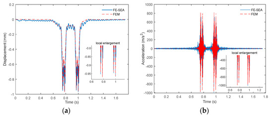
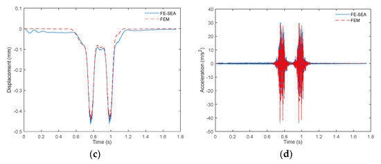
Figure 3.
Vertical vibration response. (a) Vertical displacement of the rail. (b) Vertical acceleration of the rail. (c) Vertical displacement of the track slab. (d) Vertical acceleration of the track slab.
In the FEM model, each layer of the track–bridge system is discretized into 251 elements, totaling 2008 elements. The comparison shows that the hybrid method greatly improves computational efficiency, completing the simulation in approximately 13 s, compared to around 120 s for the FEM model. In addition, the rail vibration displacement and acceleration time histories calculated by both methods show excellent consistency. The displacement amplitude of the rail is 0.9663 mm (hybrid method) and 0.9621 mm (FEM), with an error of 0.44%. The acceleration amplitude of the rail is (hybrid method) and (FEM), with an error of 1.15%. The displacement amplitude of the track slab is 0.4645 mm (hybrid method) and 0.4456 mm (FEM), with an error of 4.24%. The acceleration amplitude of the track slab is (hybrid method) and (FEM), with an error of 3.71%. The results indicate that under short-wavelength irregularity excitation, the rail exhibits relatively high vibration accelerations but small vibration displacements. Meanwhile, both the acceleration and displacement of the track slab are substantially reduced, highlighting the excellent vibration-damping performance of the rail fasteners. These differences fall within acceptable engineering limits, further verifying the accuracy and efficiency of the hybrid method for rapid vibration prediction of track–bridge structures. This establishes a solid foundation for the multi-objective optimization analysis presented in the subsequent sections.
4. Vibration Control Analysis of Track–Bridge Structure Based on TIDs
4.1. TID-Based Vibration Control Model for Track–Bridge Structures
In the four-layer track–bridge structure, Tuned Inertia Dampers (TIDs) are added to further analyze their vibration control effectiveness under high-frequency excitation caused by short-wavelength irregularities. A total of TIDs with identical parameters are installed at equal intervals between the rail and the track slab, as shown in Figure 4. In the figure, the parameters , , and represent the inertance, damping coefficient, and stiffness of the TID, respectively, and denotes the displacement of the inertance mass.

Figure 4.
TID control analysis model.
Let the distance from the first TID to the bridge node be , and the spacing between TIDs be . The coordinate of the ith TID is then defined as
According to the working principle of TIDs, the output of each device depends on the relative acceleration between the rail and the track slab at the connection points [23,24], i.e., , where and are the accelerations of the TID and track slab at the respective contact points . By introducing the TID displacement into the displacement vector of Equation (35), the new displacement vector becomes
The total force generated by all TIDs is given by
where
is the identity matrix, and is the effective inertial mass matrix generated by the TIDs.
The stiffness and damping matrices of the TIDs are calculated similarly to those of discrete elastic supports and are derived from equations
where .
By incorporating the effective inertial mass, stiffness, and damping matrices of the TIDs into Equation (35), we obtain
Solving this equation yields the vibration response of the track–bridge structure with TID control.
4.2. Analysis of TID Control Effectiveness on Rail Vibration
According to the results in Section 3.3, when short-wavelength irregularities are used as high-frequency excitation input to the rail, they generate a significant acceleration response but relatively small displacement response. Therefore, the primary goal of TID implementation is to reduce the acceleration response of the rail.
First, the control effectiveness of TIDs with different parameters on the acceleration amplitude of the rail () is analyzed. Meanwhile, the variations in the root-mean-square value and stabilization time of the rail acceleration (these control indices are, respectively, denoted as and ) are evaluated when the acceleration amplitude reaches its minimum. The stabilization time is defined as the time when the acceleration decreases to 5% of its peak value and remains below that value thereafter.
Considering installation cost and engineering feasibility, the parameter ranges for TID, , , and , are selected as , , and , respectively. The step size for is set to 1; for , nine values are evenly selected within each exponential segment; and for , four values are selected with equal logarithmic intervals, and the units are , , and , respectively. By substituting these parameters into Equation (39), the rail acceleration amplitude is calculated. The optimal value of is selected for each , and the corresponding and time are obtained and compared to the uncontrolled case, as shown in Figure 5. The optimal TID parameters for each are listed in Table 2.
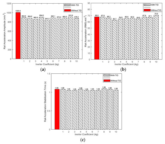
Figure 5.
TID control results. (a) Optimal value of . (b) corresponding to the minimum . (c) corresponding to the minimum .

Table 2.
Optimized design parameters of the TID.
Results Analysis:
- As shown in Figure 5a, TIDs with different inertance coefficients can all reduce the acceleration amplitude of the rail to varying degrees when their respective optimal control parameters are applied. When , the global minimum value of is achieved, decreasing from 1005.6 m/s2 to 841.0 m/s2, representing a reduction rate of 16.37%. At this point, the optimal TID stiffness coefficient is and the damping coefficient is . The corresponding working frequency of the TID is calculated to be 1006.6 Hz. This indicates that when the working frequency of the TID is close to the first pinned–pinned resonance frequency of the rail, the TID can effectively suppress high-frequency vibrations induced by high-frequency excitation. However, if the damping is too small or too large, the control effectiveness of the TID will be diminished.
- From Figure 5b,c, in combination with the parameter values listed in Table 2, it is observed that when the inertance coefficient is too small or too large, the root-mean-square acceleration may become comparable to or even exceed the uncontrolled case. In addition, when the damping coefficient is too small, the stabilization time increases. This indicates that appropriately increasing the damping coefficient can reduce the acceleration stabilization time. Under the optimal control parameters for , both and are smaller than those in the uncontrolled case, demonstrating that optimal reduction in acceleration amplitude does not lead to deterioration in either the RMS value or stabilization time of the rail acceleration.
4.3. Adverse Effects of TID on Track Slab Vibration
To further investigate the impact of TID installation on the vibration acceleration of the underlying structures, the vibration acceleration amplitude of the track slab is calculated based on the optimal TID control parameters corresponding to each inertance value, as provided in Table 2. Additionally, using the TID parameter ranges defined in Section 4.2, the minimum for each inertance value is computed. The results are shown in Figure 6; the bold italic numbers in the figure represent the difference between the acceleration amplitude of the track slab corresponding to the minimum rail acceleration amplitude and that in the uncontrolled case.
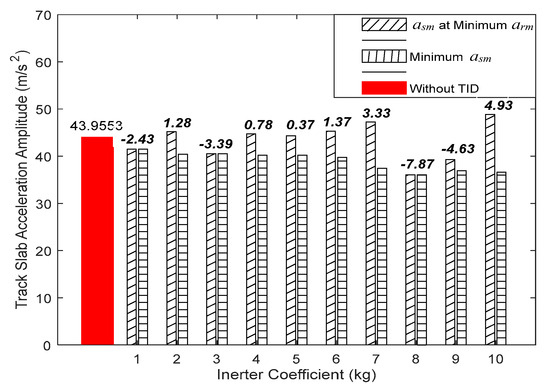
Figure 6.
Adverse effect of TID on track slab vibration acceleration amplitude.
The results indicate that the minimum value of for each inertance coefficient is lower than the uncontrolled case. However, the value of corresponding to the minimum is not always the smallest and may even exceed the uncontrolled result. In particular, when reaches its global minimum (), is also greater than the uncontrolled case, indicating a clear adverse effect. In particular, the maximum increase in the vibration acceleration amplitude of the track slab is 4.93 m/s2, accounting for an 11.22% rise. This demonstrates that excessive suppression of rail vibration may lead to amplified vibration in the lower structural layers. Therefore, when designing TID control parameters in practical engineering applications, it is essential to not only target vibration reduction in the upper (rail) structure but also to consider the influence of TID on the lower layers. The goal should be to minimize the downward transfer of vibrational energy.
4.4. Multi-Objective Optimization of TID Design Parameters
As revealed in the previous section, when a TID achieves optimal control performance for rail vibration, it may introduce a significant adverse effect on the vibration of the track slab. Therefore, it is necessary to comprehensively consider the vibration reduction effects on both the rail and the track slab when designing reasonable TID parameters.
To obtain the optimal design parameters of the TID, this section treats the TID parameters as decision variables and takes the rail acceleration amplitude and the track slab acceleration amplitude as dual objective functions. Meanwhile, two additional rail vibration control indicators—namely, the root-mean-square value and the stabilization time —are considered as constraints to ensure that they do not exceed the uncontrolled results. Based on the optimal parameter ranges identified in Section 4.2, an appropriate parameter search space is defined, and a multi-objective optimization control model is formulated as follows:
Here, , , , and denote the corresponding values in the uncontrolled case.
The computational efficiency of solving this model primarily depends on the speed at which the two objective functions are evaluated, as each feasible solution requires solving for both the rail and track slab acceleration amplitudes. Thanks to the high efficiency of the proposed FE-SEA hybrid method, the model is solved using the multi-objective genetic algorithm (MOGA) toolbox in MATLAB2018(a). The Pareto front is obtained, and based on a trade-off strategy, six tentative optimal solutions are selected, as shown in Figure 7. For each tentative optimal solution, the corresponding TID parameters are extracted, and the values and reduction rates of all control indicators are calculated. The comprehensive control rate of rail vibration is defined
where , , and denote the reduction rates of the rail acceleration amplitude, RMS acceleration, and stabilization time, respectively. The results are summarized in Table 3.
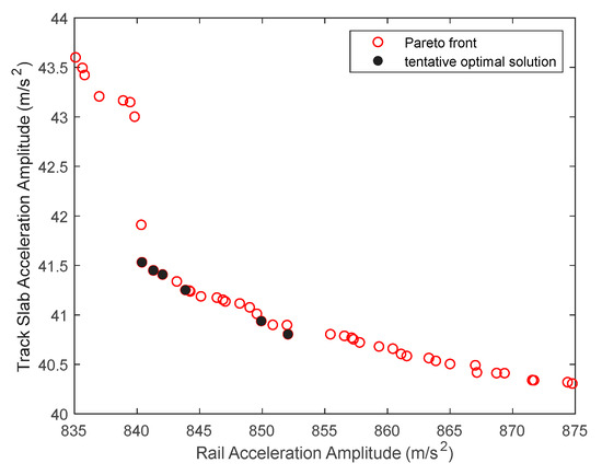
Figure 7.
Pareto front of multi-objective optimization.

Table 3.
Vehicle information for the initial calibration.
As shown in Figure 7, when the rail acceleration amplitude decreases, the acceleration amplitude of the track slab gradually increases. This further demonstrates that improving the vibration control performance of the TID on the rail may lead to a deterioration in its control effect on the track slab.
According to Table 3, Solutions 1 and 3 exhibit the highest and identical comprehensive control rates for rail vibration. Since the acceleration amplitude of the rail is lower in Solution 1, it is selected as the final optimal solution in this study. This solution eliminates the adverse effect of the TID on the track slab while controlling rail vibration, resulting in a 5.47% reduction in the acceleration amplitude of the track slab.
Using the TID parameters in Solution 1, the time-history curves of rail and track slab acceleration are plotted, as shown in Figure 8.
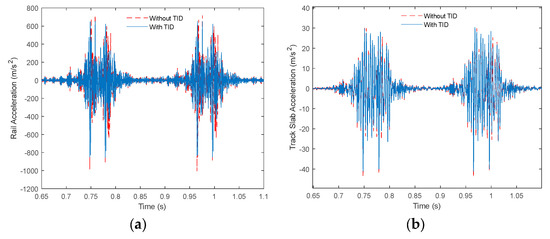
Figure 8.
Comparison diagram of optimal control results. (a) Vertical acceleration of the track slab. (b) Vertical acceleration of the track slab.
As shown in Figure 8, under the control of the TID with optimal parameters, not only is the acceleration amplitude of the rail vibration reduced, but the overall acceleration response is also effectively suppressed. In addition to the rail, the vibration acceleration of the track slab is also effectively suppressed to some extent, indicating that the TID provides a global improvement in vibration control.
In addition, the vertical displacement and vertical acceleration amplitudes of the car body under this TID configuration are 0.9951 mm and 0.1178 m/s2, respectively. Compared to the uncontrolled case (1.160 mm for displacement amplitude and 0.2244 m/s2 for acceleration amplitude), the reductions are 14.22% and 47.5%, respectively. These results indicate that the optimally tuned TID not only effectively suppresses rail vibration but also significantly improves the vibration performance of the car body, thereby enhancing passenger ride comfort.
5. Conclusions
In this study, a vertical vibration analysis model for a vehicle-track-bridge coupled system was developed based on the FE-SEA hybrid method. Taking short-wavelength irregularities as high-frequency excitation, the vibration responses of the rail and track slab were analyzed. To address the adverse effect of TIDs on track slab vibration, a multi-objective optimization model was established. The following conclusions are drawn:
- By comparing the results and computational efficiency of the conventional finite element method (FEM), the FE-SEA hybrid method was shown to provide both high accuracy and computational efficiency for analyzing the vertical vibration of track-bridge structures. This significantly reduces the computational cost of subsequent TID parameter optimization. It was also found that short-wavelength irregularities as high-frequency excitation induce large acceleration but relatively small displacement in the rail.
- The proposed numerical model for the vehicle-track-bridge system enables the effects of TIDs on the track structure to be incorporated conveniently in matrix form. The model can be easily extended to other types of vibration dampers by modifying the corresponding parameters and matrices. This provides a new design approach and theoretical foundation for vibration control analysis in vehicle-track-bridge coupled systems.
- Installing TIDs between the rail and the track slab effectively suppresses rail vibration. When the TID’s working frequency approaches the first pinned-pinned resonance frequency of the rail, the control performance against high-frequency rail vibration caused by short-wavelength irregularities is optimal. Under this condition, the rail acceleration amplitude can be reduced by 16.37%, without increasing the RMS value or stabilization time of the rail acceleration. However, the same TID parameters result in a significant increase in the vibration acceleration amplitude of the track slab, with a maximum increase of 11.22%, indicating an adverse effect.
- Enhancing the vibration control effect of TIDs on the rail generally weakens their effect on the track slab. Using the proposed multi-objective optimization model and a genetic algorithm, the optimal TID design parameters were determined asUnder these parameters, the rail and track slab acceleration amplitudes were reduced by 16.43% and 5.47%, respectively. The comprehensive rail control rate was 12.45%, effectively mitigating the adverse effect of increased track slab vibration caused by TID-based rail vibration suppression.
- The optimally tuned TID also reduced the vertical displacement and vertical acceleration amplitudes of the car body by 14.22% and 47.5%, respectively. This indicates that the TID vibration control parameters proposed in this study not only suppress rail vibration but also significantly improve the dynamic performance of the vehicle, thereby enhancing passenger ride comfort.
This study focuses on a two-dimensional vertical vibration model and utilizes a multi-objective optimization framework to address the adverse effects of tuned inerter dampers (TIDs) in controlling the vertical vibrations of track–bridge structures, offering a new design approach and theoretical guidance. The analysis is limited to a single train speed and does not consider the full three-dimensional dynamic response of the structure. Future work may apply the proposed method to various train speeds to determine the corresponding optimal TID designs, or extend the model to three dimensions. Additionally, under more realistic boundary conditions and in conjunction with field experiments, the effectiveness of TIDs in structural vibration and noise reduction can be systematically evaluated.
Author Contributions
X.H.: Methodology: writing—original draft and visualization; Q.F.: Theoretical guidance; M.Y.: Article translation; J.L.: Checking article format. All authors have read and agreed to the published version of the manuscript.
Funding
This research was funded by the Science and Technology Research Project of the Jiangxi Provincial Department of Education, China [Grant Number GJJ212516], and the Railway Basic Research Joint Fund of the National Natural Science Foundation of China and China State Railway Group Co., Ltd. [Grant Number U2468226].
Institutional Review Board Statement
Not applicable.
Informed Consent Statement
Not applicable.
Data Availability Statement
The data presented in this study are available in the article.
Conflicts of Interest
The authors declare no conflicts of interest.
References
- Langley, R.S.; Bremner, P. A hybrid method for the vibration analysis of complex structural-acoustic systems. J. Acoust. Soc. Am. 1999, 105, 1657–1671. [Google Scholar] [CrossRef]
- Langley, R.S.; Cotoni, V. Response variance prediction for uncertain vibro-acoustic systems using a hybrid deterministic-statistical method. J. Acoust. Soc. Am. 2007, 122, 3445–3463. [Google Scholar] [CrossRef]
- Luo, W.J.; Lei, X.Y.; Lian, S.L. Analysis on vibration of ballastless track–bridge system based on hybrid FE–SEA method. J. China Railw. Soc. 2013, 35, 94–101. [Google Scholar] [CrossRef]
- Lei, X.Y.; Weng, L.X.; Yu, L.L.; Wang, P.S.; Kun, L. Structural noise of box girder for elevated track: An analysis based on the hybrid FE–SEA model and experiment. J. East China Jiaotong Univ. 2023, 40, 1–8. [Google Scholar] [CrossRef]
- Sheng, X.; Zhao, C.Y.; Wang, P.; Chen, J.H.; Wei, X. Influence of Fastener Stiffness on Rail Sound Power Characteristics in Ballastless Track. J. Southwest Jiaotong Univ. 2018, 53, 928–936+1094. [Google Scholar]
- Gao, G.Y.; Yao, S.F.; Sun, Y.M. 2.5D Finite Element Analysis of Unsaturated Ground Vibration Induced by High-Speed Train Loads. Earthq. Eng. Eng. Vib. 2019, 39, 28–39. [Google Scholar] [CrossRef]
- Quan, W.; Yu, H.; Deng, L.; Liu, X.; Wang, D. Study on the seismic performance of high-speed railway extradosed cable-stayed bridge considering CRTS III slab ballastless track structure. J. Phys. Conf. Ser. 2024, 2736, 012044. [Google Scholar] [CrossRef]
- Zhang, X.Y.; Lei, X.; Luo, K. Application of TMD in multi-order modal vibration control of a simply supported box girder. Noise Vib. Control 2019, 39, 78–83. [Google Scholar]
- Zhang, X.Y.; Lei, X.; Luo, K. A model test study on controlling vibration of an elevated track box girder structure with TMD. J. Vib. Shock 2021, 40, 220–226+233. [Google Scholar]
- Sheng, P.; Zhang, Z.; Jing, S.; Zhao, F. Isolation performance of the quasi-zero stiffness isolation system enhanced by mixed tuned inerter damper. Int. J. Struct. Stab. Dyn. 2024. prepublish. [Google Scholar] [CrossRef]
- Liu, L.; Luo, J.; Qin, R.; Pan, Z.; Di, B.; Pang, S. Damping performance and optimal design of mid-story isolation system with tuned inerter damper. Int. J. Struct. Stab. Dyn. 2024. prepublish. [Google Scholar] [CrossRef]
- Shen, J.L.; Wang, S.; Chen, Z.Q.; Feng, Z.Q.; Huang, Z.W.; Hua, X.G. Numerical simulation and experimental study of electromagnetic eddy current damper for railway vehicles. J. Railw. Sci. Eng. 2022, 19, 1433–1441. [Google Scholar] [CrossRef]
- Song, J.; Fang, X.; Bi, K.; Ding, H.; Qin, H. Tuned inerter damper for adjacent bridges vibration control considering nonlinearities. Eng. Struct. 2025, 325, 119504. [Google Scholar] [CrossRef]
- Zhang, T.Y.; Wang, W.H.; Li, X. Optimization and evaluation of tuned inerter-based dampers for mitigating coupled responses of offshore wind turbines. Ocean Eng. 2024, 312, 119146. [Google Scholar] [CrossRef]
- Yang, Z.; Feng, Q.S.; Zhang, L.; Lu, J.F. Vertical vibration control of curved track structure based on inertial enhancement effect. J. Traffic Transp. Eng. 2024, 24, 204–216. [Google Scholar]
- Zhang, Q.; Cheng, Z.B.; Shi, Z.F. Low-frequency vibration mitigation performance of floating slab tracks with inerter enhanced dynamic vibration absorbers. J. China Railw. Soc. 2024, 46, 102–111. [Google Scholar]
- Sheng, X.; Zeng, H.K.; Shi, C.; Zhang, Y.; Du, Y.L. Study on low-frequency vibration mitigation characteristics of TID-vibration-isolator floating slab track. Eng. Mech. 2023, 40, 49–58. [Google Scholar]
- Wei, W.; Zhu, S.; Zhai, W.; Zhang, Q. A low-frequency vibration isolation method for floating slab tracks based on tuned viscous mass dampers. Sci. China Technol. Sci. 2021, 51, 1391–1400. [Google Scholar]
- Chen, L.; Shen, Y.J.; Yang, X.F. Design and experiment of vehicle suspension based on inerter-spring structure. J. Vib. Shock 2014, 33, 83–87. [Google Scholar] [CrossRef]
- Xu, L. Matrix formulation of the wheel–rail contact element in train–track dynamic analysis. Appl. Math. Model. 2025, 140, 115874. [Google Scholar] [CrossRef]
- Lei, X.Y. High-Speed Railway Track Dynamics: Model, Algorithm and Application; Science Press: Beijing, China, 2015. [Google Scholar]
- Xu, L.; Zhai, W.M. Track irregularity probabilistic model. J. Traffic Transp. Eng. 2018, 18, 56–63. [Google Scholar]
- Huang, W.; Jiang, H.; Huang, Y.; Wang, H. An inerter-enhanced bistable nonlinear energy sink for seismic response control of building structures. J. Build. Eng. 2024, 96, 110384. [Google Scholar] [CrossRef]
- Qiu, Z.; Han, S.; Na, J.; Wang, C.; Bai, Y.-T. Vertical suspension optimization for a high-speed train with PSO intelligent method. Comput. Intell. Neurosci. 2021, 2021, 1526792. [Google Scholar] [CrossRef]
Disclaimer/Publisher’s Note: The statements, opinions and data contained in all publications are solely those of the individual author(s) and contributor(s) and not of MDPI and/or the editor(s). MDPI and/or the editor(s) disclaim responsibility for any injury to people or property resulting from any ideas, methods, instructions or products referred to in the content. |
© 2025 by the authors. Licensee MDPI, Basel, Switzerland. This article is an open access article distributed under the terms and conditions of the Creative Commons Attribution (CC BY) license (https://creativecommons.org/licenses/by/4.0/).