

Characterization of Solid Particulates to Be Used as Storage as Well as Heat Transfer Medium in Concentrated Solar Power Systems

 , , , , , , and
Abstract
1. Introduction
2. Methodology
2.1. Density Measurement
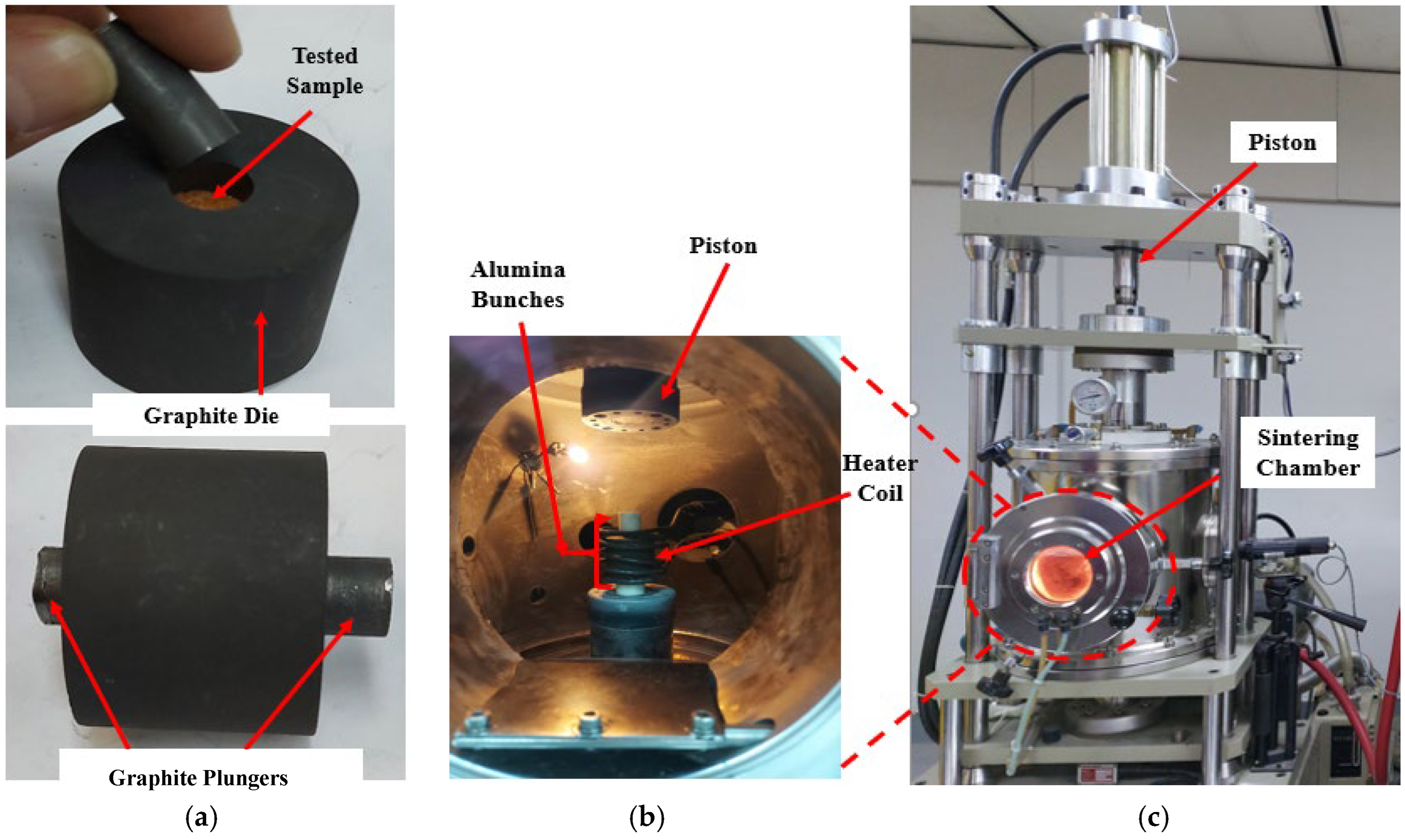
2.2. Sintering Test
2.3. Thermal Conductivity Measurement & Calculation
3. Results and Discussion
3.1. Bulk Density
3.2. Sintering of Candidate Materials
3.3. Thermal Conductivity
4. Conclusions
- Particulate size and size distribution have a significant effect on bulk density. For most of the particles, their porosity ranges from 35% to 45%, consistent with the commonly expected value of 40% for monodisperse particles. In contrast, the porosity of the USOS material is much lower, 24% loose and 18% tapped, which is indicative of the presence of fines in the mix filling the spaces that are voids between more uniform particles.
- The tapped bulk density for all particle materials is always greater than the loose density for all particles. In the case of 0.5 mm CB, the beads are so uniform and smooth that the effect of tapping is minimal.
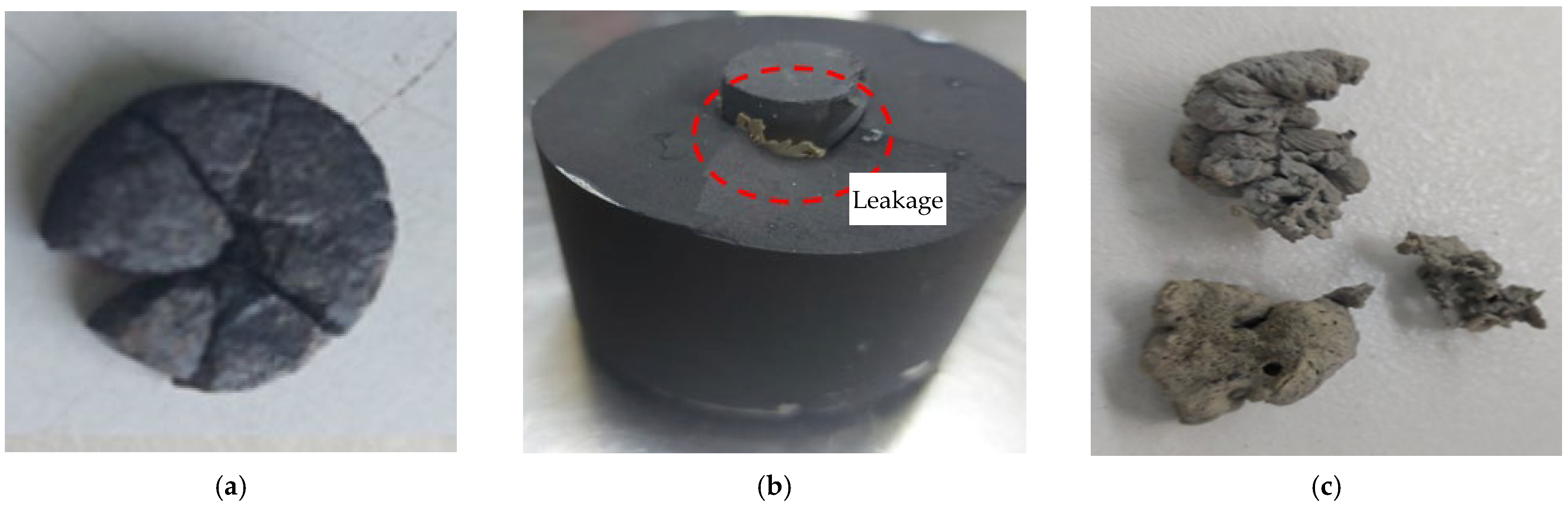
- During the sintering test, when the temperature and pressure were raised to 1300 °C and 40 MPa, respectively, for RWS (0.5–1 mm), the specimen did not exhibit any signs of sintering. For RWS (0.21–0.425 mm), only weak binding formed at the high pressure of 50 MPa. Sintered RRS was produced at 40 MPa and 1300 °C, and CB at 20 MPa and 1100 °C. Similar behavior was displayed by SOS and RRS. At 800 °C, USOS solidified, while at higher temperatures, it melted. This demonstrates why USOS cannot be used in high-temperature particle-based CSP systems as TES or an HTM.
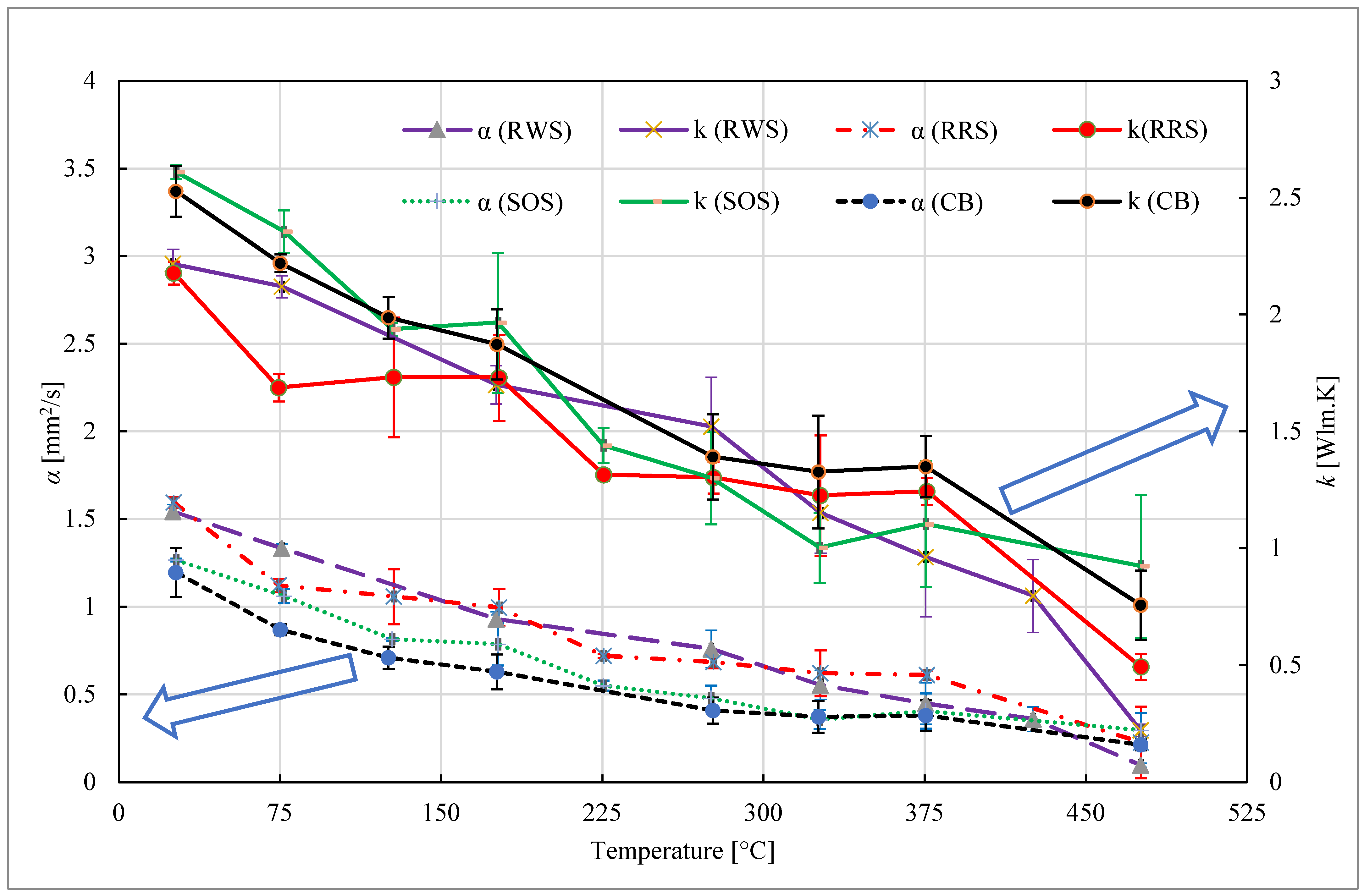
- Particulate materials’ thermal diffusivity and thermal conductivity decrease as the temperature rises, reaching their lowest values at the highest temperatures. This indicates that a bigger-size heat exchanger is needed to run at elevated temperatures. When comparing various particulates, RWS has the lowest thermal conductivity and minimum thermal diffusivity of 0.15 mm2/s and 0.46 W/mK, respectively, at the maximum temperature of 475.5 °C. Conversely, at the same temperature, the maximum values of the RRS are 1.25 W/mK and 0.432 mm2/s, respectively.
Author Contributions
Funding
Institutional Review Board Statement
Informed Consent Statement
Data Availability Statement
Acknowledgments
Conflicts of Interest
References
- Heller, L. Literature review on heat transfer fluids and thermal energy storage systems in CSP plants. Sterg Rep. 2013. Available online: https://sterg.sun.ac.za/wp-content/uploads/2011/08/HTF_TESmed_Review_2013_05_311.pdf (accessed on 29 July 2025).
- Qazi, S. Solar Thermal Electricity and Solar Insolation. In Standalone Photovoltaic (PV) Systems for Disaster Relief and Remote Areas; Elsevier, B.V.: Amsterdam, The Netherlands, 2017. [Google Scholar] [CrossRef]
- Breeze, P. Solar Towers. In Solar Power Generation; Elsevier, B.V.: Amsterdam, The Netherlands, 2016; pp. 35–40. [Google Scholar]
- Ding, W.; Bonk, A.; Bauer, T. Corrosion behavior of metallic alloys in molten chloride salts for thermal energy storage in concentrated solar power plants: A review. Front. Chem. Sci. Eng. 2018, 12, 564–576. [Google Scholar] [CrossRef]
- Mehos, M.; Turchi, C.; Vidal, J.; Wagner, M.; Ma, Z.; Ho, C.; William, K.; Andraka, C.; Kruizenga, A. Concentrating Solar Power Gen3 Demonstration Roadmap; Nrel/Tp-5500-67464; NREL: Golden, CO, USA, 2017; pp. 1–140. Nrel/Tp-5500-67464. [Google Scholar] [CrossRef]
- Ding, W.; Shi, H.; Xiu, Y.; Bonk, A.; Weisenburger, A.; Jianu, A.; Bauer, T. Hot corrosion behavior of commercial alloys in thermal energy storage material of molten MgCl2/KCl/NaCl under inert atmosphere. Sol. Energy Mater. Sol. Cells 2018, 184, 22–30. [Google Scholar] [CrossRef]
- Ding, W.; Bonk, A.; Bauer, T. Molten chloride salts for next generation CSP plants: Selection of promising chloride salts & study on corrosion of alloys in molten chloride salts. AIP Conf. Proc. 2019, 2126, 200014. [Google Scholar] [CrossRef]
- Ma, Z.; Davenport, P.; Zhang, R. Design analysis of a particle-based thermal energy storage system for concentrating solar power or grid energy storage. J. Energy Storage 2020, 29, 101382. [Google Scholar] [CrossRef]
- Saeed, R.S.; Alswaiyd, A.; Saleh, N.S.; Alaqel, S.; Djajadiwinata, E.; El-Leathy, A.; Danish, S.N.; Al-Ansary, H.; Jeter, S.; Al-Suhaibani, Z.; et al. Characterization of Low-Cost Particulates Used as Energy Storage and Heat-Transfer Medium in Concentrated Solar Power Systems. Materials 2022, 15, 2946. [Google Scholar] [CrossRef]
- Bradshaw, R.W.; Dawson, D.B.; De la Rosa, W.; Gilbert, R.; Goods, S.H.; Hale, M.J.; Jacobs, P.; Jones, S.A.; Kolb, G.J.; Pacheco, J.E.; et al. Final Test and Evaluation Results from the Solar Two Project. 2002, SAND2002-0120. Available online: https://www.osti.gov/biblio/793226 (accessed on 29 July 2025). [CrossRef]
- Bonk, A.; Sötz, V.; Bauer, T. Molten Salt Chemistry in the Lab- & MW-Scale—Operational Experiences from the Molten Salt Storage Facility TESIS at DLR; ResearchGate GmbH: Berlin, Germany, 2018. [Google Scholar]
- High Performance Fluids for Precise Temperature Control Selection Guide. Available online: https://www.therminol.com/sites/therminol/files/documents/TF8691.pdf (accessed on 29 July 2025).
- Mills, B.H.; Ho, C.K.; Schroeder, N.R.; Shaeffer, R.; Laubscher, H.F.; Albrecht, K.J. Design Evaluation of a Next-Generation High-Temperature Particle Receiver for Concentrating Solar Thermal Applications. Energies 2022, 15, 1657. [Google Scholar] [CrossRef]
- Adapa, S.R.; Zhang, X.; Feng, T.; Chung, K.M.; Albrecht, K.J.; Ho, C.K.; Madden, D.A.; Chen, R. Thermophysical Properties and Heat Transfer Coefficients for Flowing Packed Particle Beds. arXiv 2024, arXiv:2403.15. [Google Scholar]
- Jiang, K.; Du, X.; Kong, Y.; Xu, C.; Ju, X. A comprehensive review on solid particle receivers of concentrated solar power. Renew. Sustain. Energy Rev. 2019, 116, 109463. [Google Scholar] [CrossRef]
- Khan, M.I.; Asfand, F.; Al-Ghamdi, S.G. Progress in technology advancements for next generation concentrated solar power using solid particle receivers. Sustain. Energy Technol. Assess. 2022, 54, 102813. [Google Scholar]
- Ricken, M.; Nölting, J.; Riess, I. Specific heat and phase diagram of nonstoichiometric ceria (CeO2−x). J. Solid State Chem. 1984, 54, 89–99. [Google Scholar] [CrossRef]
- Skauge, A.; Fuller, N.; Hepler, L.G. Specific heats of clay minerals: Sodium and calcium kaolinites, sodium and calcium montmorillonites, illite, and attapulgite. Thermochim. Acta 1983, 61, 139–145. [Google Scholar] [CrossRef]
- Liu, J.; Li, Y.; Li, S.; Xu, N.; Xiang, R.; Wang, Q. Micro-porosity and properties of light-weight insulation refractories based on calcined flint clay. Trans. Indian Ceram. Soc. 2019, 78, 7–12. [Google Scholar] [CrossRef]
- Kang, Q.; Flamant, G.; Dewil, R.; Baeyens, J.; Zhang, H.L.; Deng, Y.M. Particles in a circulation loop for solar energy capture and storage. Particuology 2019, 43, 149–156. [Google Scholar] [CrossRef]
- Prinz, M.; Harlow, G.E.; Peters, J.; Mottana, A. Simon and Schuster’s Guide to Rocks and Minerals; Simon and Schuste: New York, NY, USA, 1978. [Google Scholar]
- Don, W.G.; Perry, R.H. Perry’s Chemical Engineers’ Handbook, 8th ed.; McGraw-Hill Education: Columbus, OH, USA, 2008. [Google Scholar]
- Grimvall, G. Thermophysical Properties of Materials; Elsevier: Amsterdam, The Netherlands, 1999. [Google Scholar]
- Knott, R.C.; Sadowski, D.L.; Jeter, S.M.; Abdel-Khalik, S.I.; Al-Ansary, H.A.; El-Leathy, A. Sintering of solid particulates under elevated temperature and pressure in large storage bins for thermal energy storage. In Energy Sustainability; American Society of Mechanical Engineers: New York, NY, USA, 2014; Volume 45868, p. V001T02A042. [Google Scholar]
- Tregambi, C.; Bevilacqua, C.; Cammarota, A.; Chirone, R.; Salatino, P.; Solimene, R.; Bassetti, F.; Picarelli, A.; Magaldi, M. Experimental characterization of granular materials for directly irradiated fluidized bed solar receivers. AIP Conf. Proc. 2019, 2126, 030060. [Google Scholar]
- Nie, F.; Cui, Z.; Bai, F.; Wang, Z. Properties of solid particles as heat transfer fluid in a gravity driven moving bed solar receiver. Sol. Energy Mater. Sol. Cells 2019, 200, 110007. [Google Scholar] [CrossRef]
- Diago, M.; Iniesta, A.C.; Soum-Glaude, A.; Calvet, N. Characterization of desert sand to be used as a high-temperature thermal energy storage medium in particle solar receiver technology. Appl. Energy 2018, 216, 402–413. [Google Scholar] [CrossRef]
- Baumann, T.; Zunft, S. Properties of granular materials as heat transfer and storage medium in CSP application. Sol. Energy Mater. Sol. Cells 2015, 143, 38–47. [Google Scholar] [CrossRef]
- Lv, S.; Zhu, G.; Han, J.; Wang, Z. Performance of solid particles flow thermal storage material made of desert sand. Energy Sources Part A: Recovery Util. Environ. Eff. 2018, 40, 1852–1876. [Google Scholar] [CrossRef]
- Saeed, R.; Alaqel, S.; Djajadiwinata, E.; Saleh, N.S.; Alswaiyd, A.; Al-Ansary, H.; Danish, S.N.; El-Leathy, A.; Al-Suhaibani, Z.; Jeter, S.; et al. Experimental analysis of micro-cavity influence on the effective solar absorptance of white sand curtain on porous obstructions of particle heating receivers. Case Stud. Therm. Eng. 2025, 66, 105769. [Google Scholar] [CrossRef]
- Danish, S.N.; Badawi, K.M.; Al-Ansary, H.; El-Leathy, A.; Alswaiyd, A.; Saeed, R.; Saleh, N.S.; Djajadiwinata, E.; Alaqel, S.; Al-Suhaibani, Z.; et al. Techno-economic analysis of the integration of an innovative particle-based concentrating solar power system with a thermally driven cooling system. Energy Convers. Manag. 2024, 320, 118968. [Google Scholar] [CrossRef]
- El-Leathy, A.; Jeter, S.; Al-Ansary, H.; Danish, S.N.; Saeed, R.; Abdel-Khalik, S.; Golob, M.; Djajadiwinata, E.; Al-Suhaibani, Z. Thermal performance evaluation of lining materials used in thermal energy storage for a falling particle receiver based CSP system. Sol. Energy 2019, 178, 268–277. [Google Scholar] [CrossRef]
- Alaqel, S.; El-Leathy, A.; Al-Ansary, H.; Djajadiwinata, E.; Saleh, N.; Danish, S.; Saeed, R.; Alswaiyd, A.; Al-Suhaibani, Z.; Jeter, S. Experimental investigation of the performance of a shell-and-tube particle-to-air heat exchanger. Sol. Energy 2020, 204, 561–568. [Google Scholar] [CrossRef]
- Saleh, N.S.; Alaqel, S.; Djajadiwinata, E.; Saeed, R.S.; Al-Suhaibani, Z.; Zeitoun, O.; Al-Ansary, H.; Alswaiyd, A.; Danish, S.; El-Leathy, A. Experimental Investigation of a Moving Packed-Bed Heat Exchanger Suitable for Concentrating Solar Power Applications. Appl. Sci. 2022, 12, 4055. [Google Scholar] [CrossRef]
- Saeed, R.; Alswaiyd, A.; Saleh, N.S.; Alaqel, S.; Djajadiwinata, E.; Al-Ansary, H.; Danish, S.N.; El-Leathy, A.; Al-Suhaibani, Z.; Almutairi, Z. An experimental investigation of chevron-shaped discrete structure configuration on the particle flow behavior of particle heating receivers. Results Eng. 2024, 21, 101786. [Google Scholar] [CrossRef]
- El-Leathy, A.; Danish, S.N.; Al-Ansary, H.; Al-Suhaibani, Z.; Al-Tamimi, S.; Al-Turki, A.; Saeed, R.S.; Saleh, N.S.; Djajadiwinata, E.; Alaqel, S. Optimization of Thermal Energy Storage System for a 1.3 MWe Particle-Based Concentrated Solar Power Facility. In Proceedings of the 2023 24th International Middle East Power System Conference, Mansoura, Egypt, 19 December 2023; pp. 1–7. [Google Scholar] [CrossRef]
- Alaqel, S.S.M.A.; Al-Ansary, H.A.; Sarfraz, M.M.; Repole, K.K.; Djajadiwinata, E.; Saleh, N.S.; Saeed, R.S.A.; Alzahrani, S.M.; Alsuhaibani, Z.A.; Danish, S.N.; et al. Skip Hoist System for a Particle-Based High-Temperature Power Tower Plant. U.S. Patent 12,234,133, 2025. [Google Scholar]
- Chung, K.M.; Zeng, J.; Adapa, S.R.; Feng, T.; Bagepalli, M.V.; Loutzenhiser, P.G.; Albrecht, K.J.; Ho, C.K.; Chen, R. Measurement and analysis of thermal conductivity of ceramic particle beds for solar thermal energy storage. Sol. Energy Mater. Sol. Cells 2021, 230, 111271. [Google Scholar] [CrossRef]
- Palacios, A.; Barreneche, C.; Navarro, M.E.; Ding, Y. Thermal energy storage technologies for concentrated solar power–A review from a materials perspective. Renew. Energy 2020, 156, 1244–1265. [Google Scholar] [CrossRef]
- Siegel, N.; Kolb, G.; Kim, K.; Rangaswamy, V.; Moujaes, S. Solid Particle Receiver Flow Characerization Studies. In Energy Sustainability; Elsevier, B.V.: Amsterdam, The Netherlands, 2007; Volume 47977, pp. 877–883. [Google Scholar]
- Siegel, N.P.; Gross, M.D.; Coury, R. The development of direct absorption and storage media for falling particle solar central receivers. J. Sol. Energy Eng. 2015, 137, 041003. [Google Scholar] [CrossRef]
- Ho, C.K.; Carlson, M.; Albrecht, K.J.; Ma, Z.; Jeter, S.; Nguyen, C.M. Evaluation of alternative designs for a high temperature particle-to-SCO2 heat exchanger. In Proceedings of the ASME 2018 12th International Conference on Energy Sustainability, ES 2018, Collocated with the ASME 2018 Power Conference and the ASME 2018 Nuclear Forum, Lake Buena Vista, Florida, FL, USA, 24–28 June 2018. [Google Scholar] [CrossRef]
- Kern. Operating Instructions Electronic Precision and Analytical Balance Contents. Available online: https://www.kern-sohn.com/manuals/files/English/770-GS-GJ-BA-e-0023.pdf (accessed on 31 October 2024).
- Available online: https://www.appstate.edu/~cockmanje/labs/1103/spring/archimedes (accessed on 31 October 2024).
- KD2 Pro Thermal Properties Analyzer Operator’s Manual. Available online: https://www.catec.nl/uploads/pdf/DEC-KD2-Pro-manual_763.pdf (accessed on 31 October 2024).
- Archimedes Principle. Available online: https://analyzing-testing.netzsch.com/en/products/thermal-diffusivity-and-conductivity/lfa-457-micro-flash (accessed on 31 October 2024).
- Parker, W.J.; Jenkins, R.J.; Butler, C.P.; Abbott, G.L. Flash Method of Determining Thermal Diffusivity, Heat Capacity, and Thermal Conductivity. J. Appl. Phys. 1961, 32, 1679–1684. [Google Scholar] [CrossRef]
- Dremel 4000-4/34 Rotary Tool Kit 1.6 A Variable Speed. Available online: https://www.kvmtools.com/products/dremel-4000-4-34-rotary-tool-kit-1-6-a-variable-speed?gad_source=1 (accessed on 31 October 2024).
- Electronic Densimeter SD-200L. Available online: https://img1.17img.cn/17img/old/literature/C138301.pdf (accessed on 31 October 2024).
- Chase, M.W., Jr. NIST-JANAF Thermochemical Tables, Fourth Edition. J. Phys. Chem. Ref. Data Monogr. 1998, 1, 1–1951. [Google Scholar]
- Ho, C.K.; Christian, J.M.; Romano, D.; Yellowhair, J.; Siegel, N.; Savoldi, L.; Zanino, R. Characterization of particle flow in a free-falling solar particle receiver. J. Sol. Energy Eng. Trans. ASME 2017, 139, 1–9. [Google Scholar] [CrossRef]
- Available online: https://speciation.net/Database/Instruments/NetzschGeraetebau-GmbH/STA-409-CD-Simultaneous-thermal-analyzer-;i2007 (accessed on 17 November 2024).
- Díaz-Heras, M.; Calderón, A.; Navarro, M.; Almendros-Ibáñez, J.A.; Fernández, A.I.; Barreneche, C. Characterization and testing of solid particles to be used in CSP plants: Aging and fluidization tests. Sol. Energy Mater. Sol. Cells 2021, 219, 110793. Available online: https://www.gwdl.net/product/catalog/muffle-furnace/high-temperature-chamber-furnace-98.html (accessed on 31 October 2024). [CrossRef]
- JCGM GUM-1:2023; Guide to the Expression of Uncertainty in Measurement. The International Organization for Standardization ISO: Geneva, Switzerland, 1993.


| Material | Specific Heat (kJ/kgK) | Melting Point (°C) | Sintering Temperature (°C) | Energy Density (kJ/m3) | Density (kg/m3) | Thermal Conductivity (W/mK) | Cost ($/ton) |
|---|---|---|---|---|---|---|---|
| Quartz; SiO2 | 0.95 | 1670 | 1670–1714 | 2480 | 2600 | 0.4 | 150 |
| Sand; SiO2 | 0.95 | 1700 | 1760 | 2490 | 2550 | 1.2 | 75 |
| Cristobalite; SiO2 | 1.05 | 1713 | 1714 | 2447 | 2330 | 0.48 | 200 |
| Sintered Bauxite | 1.05 | 2000 | 1550 | 4095 | 3600 | 0.65 | 400 |
| Silicon carbide; SiC | 1.05 | 2210 | 1800 | 3380 | 3200 | 100 | 1900 |
| Alumina; Al2O3 | 1.05 | 2054 | 2072 | 4200 | 3970 | 23 | 300 |
| Olivine; (Mg,Fe)2SiO4 | 1.25 | 1870 | 1450 | 4290 | 3300 | 0.56 | 175 |
| Ceria; CeO2 [17] | 0.39 | 2340 | 1000–1400 | - | 7600 | 12 | 1610 |
| Graphite; C | 0.79 | 3652 | 900–1500 | 1131 | 2200 | 45 | 362 |
| Calcined Flint Clay; Al2O3/SiO2 [18,19] | 0.74–0.87 | 1500 | 1200 | 2730 | 3300 | 0.85 | 180 |
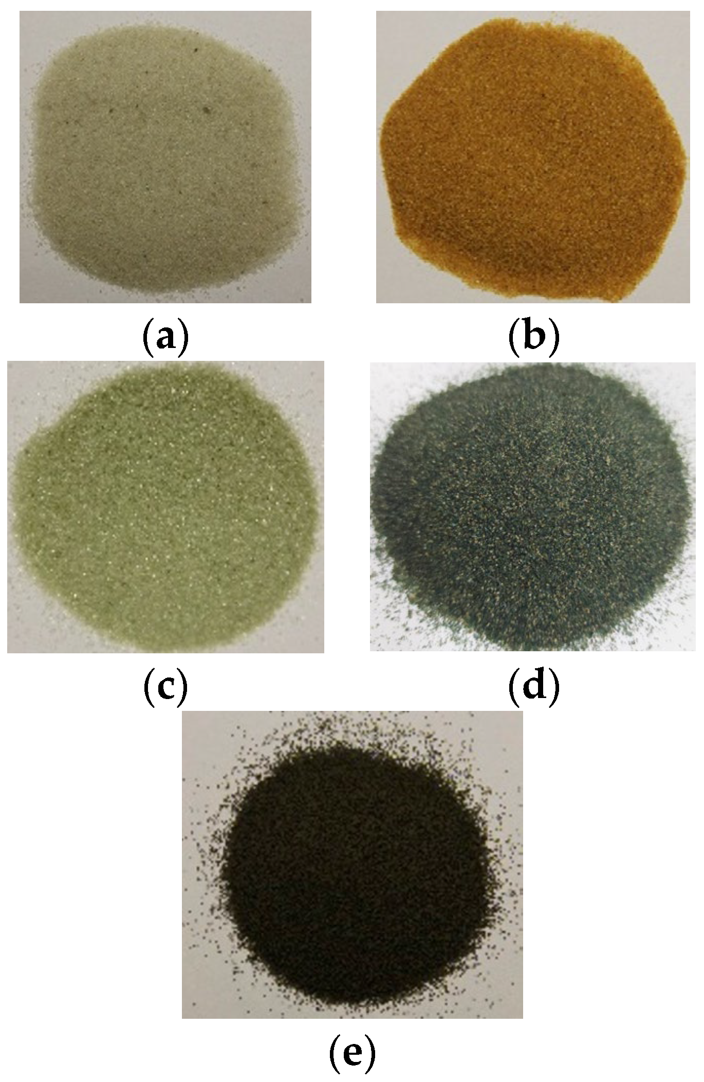
| Sample | Average Particle Diameter [µm] | Shape | Chemical Composition |
|---|---|---|---|
| RWS | 500 to 1000 | Irregular | 98% SiO2, 1.56% Al2O3, 0.44% others |
| RWS | 210 to 425 | Irregular | 98% SiO2, 1.56% Al2O3, 0.44% others |
| RRS | 210 to 425 | Irregular | 90% SiO2, 2.93% Al2O3, 3.15% Fe2O3, 2.23% CaSiO3, and 1.69% others |
| SOS * | 200 to 500 | Irregular | 59.32% O, 22.91% Mg, 12.91% Si, 4.87% Fe |
| USOS | 250 to 400 | Irregular | 50.2% SiO2, 31.4% MgO, 15.9% Fe2O3, 1.6% Al2O3, 0.7% CaO, <0.1% Ni & NiO, 0.1% Cr2O3 and <0.1% Trace Elements & Compounds |
| CB | 300 | Regular | 75% Al2O3, 11% SiO2, 9% Fe2O3, 3% TiO2, and 2% others [42] |
| Material Type | Theoretical Density [kg/m3] | Loose Density [kg/m3] | Tapped Density [kg/m3] | Porosity [38,42] × 100 | |
|---|---|---|---|---|---|
| RWS | 2756 ± 28.7 | 1571 ± 8.8 | 1653 ± 37 | 43 | Loose |
| 40 | Tapped | ||||
| RRS | 2771 ± 29 | 1574 ± 8.8 | 1679 ± 38 | 43 | Loose |
| 39 | Tapped | ||||
| SOS | 3260 ± 29.7 | 1873 ± 9.3 | 2155 ± 37 | 43 | Loose |
| 34 | Tapped | ||||
| USOS | 1913 ± 29.2 | 1445 ± 8.6 | 1572 ± 36 | 24 | Loose |
| 18 | Tapped | ||||
| CB–0.3 mm | 3321 ± 36.6 | 1796 ± 10.2 | 1944 ± 43 | 46 | Loose |
| 41 | Tapped | ||||
| CB–0.5 mm | 3321 ± 42.3 | 1813 ± 10.3 | 1828 ± 44 | 45 | Loose |
| 45 | Tapped | ||||
| Material Type | Average Diameter [mm] | Thickness [mm] | Pellet Density [kg/m3] |
|---|---|---|---|
| RRS | 12.60 | 2.93 | 2454 ± 13.3 |
| RWS | 12.60 | 3.52 | 2581 ± 16.7 |
| SOS | 12.65 | 2.96 | 3169 ± 28.7 |
| CB | 12.65 | 3.36 | 3210 ± 18.2 |
| Test No. | Sintering Temperature [°C] | RWS (500 to 1000 µm) | RRS | SOS | USOS | CB | ||||||||||
|---|---|---|---|---|---|---|---|---|---|---|---|---|---|---|---|---|
| Sintering Pressure [MPa] | Dwell Time [min] | Sintering | Sintering Pressure [MPa] | Dwell Time [min] | Sintering | Sintering Pressure [MPa] | Dwell Time [min] | Sintering | Sintering Pressure [MPa] | Dwell Time [min] | Sintering | Sintering Pressure [MPa] | Dwell Time [min] | Sintering | ||
| 1 | 800 | - | - | - | - | - | - | - | - | - | 20 | 5 | Yes ** | - | - | - |
| 2 | 1000 | 20 | 10 | No | 20 | 10 | No | 20 | 10 | No | 20 | 5 | Yes ** | 20 | 5 | No |
| 3 | 1100 | - | - | - | - | - | - | - | - | - | 20 | 5 | Fused *** | 20 | 7 | Yes |
| 4 | 1200 | 20 | 10 | No | 20 | 10 | No | 20 | 10 | No | - | - | - | - | - | - |
| 5 | 1300 | 30 | 5 | No | - | - | - | - | - | - | - | - | - | - | - | - |
| 6 | 1300 | 40 | 5 | No | - | - | - | - | - | - | - | - | - | - | - | - |
| RWS (210 to 425µm) | - | - | - | - | - | - | - | - | - | - | - | - | ||||
| 7 | 1300 | 20 | 4 | No | 20 | 5 | No | 20 | 3 | No | - | - | - | - | - | - |
| 8 | 1300 | 30 | 4 | No | 30 | 1 | No | 30 | 3 | No | - | - | - | - | - | - |
| 9 | 1300 | 40 | 4 | No | 40 | 1 | Yes | 40 | 3 | No | - | - | - | - | - | - |
| 10 | 1300 | 50 | 4 | Yes * | - | - | - | 50 | 3 | Yes | - | - | - | - | - | - |
| Sample | Thermal Conductivity [W/mK] |
|---|---|
| RWS | 0.267 ± 0.02 |
| RRS | 0.260 ± 0.02 |
| CB | 0.202 ± 0.02 |
| SOS | 0.217 ± 0.02 |
| USOS | 0.155 ± 0.02 |
Disclaimer/Publisher’s Note: The statements, opinions and data contained in all publications are solely those of the individual author(s) and contributor(s) and not of MDPI and/or the editor(s). MDPI and/or the editor(s) disclaim responsibility for any injury to people or property resulting from any ideas, methods, instructions or products referred to in the content. |
© 2025 by the authors. Licensee MDPI, Basel, Switzerland. This article is an open access article distributed under the terms and conditions of the Creative Commons Attribution (CC BY) license (https://creativecommons.org/licenses/by/4.0/).
Share and Cite
Saeed, R.; Danish, S.N.; Alaqel, S.; Saleh, N.S.; Djajadiwinata, E.; Al-Ansary, H.; El-Leathy, A.; Alswaiyd, A.; Al-Suhaibani, Z.; Almutairi, Z.; et al. Characterization of Solid Particulates to Be Used as Storage as Well as Heat Transfer Medium in Concentrated Solar Power Systems. Appl. Sci. 2025, 15, 8566. https://doi.org/10.3390/app15158566
Saeed R, Danish SN, Alaqel S, Saleh NS, Djajadiwinata E, Al-Ansary H, El-Leathy A, Alswaiyd A, Al-Suhaibani Z, Almutairi Z, et al. Characterization of Solid Particulates to Be Used as Storage as Well as Heat Transfer Medium in Concentrated Solar Power Systems. Applied Sciences. 2025; 15(15):8566. https://doi.org/10.3390/app15158566
Chicago/Turabian StyleSaeed, Rageh, Syed Noman Danish, Shaker Alaqel, Nader S. Saleh, Eldwin Djajadiwinata, Hany Al-Ansary, Abdelrahman El-Leathy, Abdulelah Alswaiyd, Zeyad Al-Suhaibani, Zeyad Almutairi, and et al. 2025. "Characterization of Solid Particulates to Be Used as Storage as Well as Heat Transfer Medium in Concentrated Solar Power Systems" Applied Sciences 15, no. 15: 8566. https://doi.org/10.3390/app15158566
APA StyleSaeed, R., Danish, S. N., Alaqel, S., Saleh, N. S., Djajadiwinata, E., Al-Ansary, H., El-Leathy, A., Alswaiyd, A., Al-Suhaibani, Z., Almutairi, Z., & Jeter, S. (2025). Characterization of Solid Particulates to Be Used as Storage as Well as Heat Transfer Medium in Concentrated Solar Power Systems. Applied Sciences, 15(15), 8566. https://doi.org/10.3390/app15158566