Article

Design and Validation of the MANTiS-32 Wireless Monitoring System for Real-Time Performance-Based Structural Assessment

Department of Disaster and Safety Engineering, Konyang University, 121 Daehak-ro, Nonsan 32992, Chungnam, Republic of Korea
*
Author to whom correspondence should be addressed.
Appl. Sci. 2025, 15(15), 8394; https://doi.org/10.3390/app15158394
Submission received: 24 June 2025 / Revised: 24 July 2025 / Accepted: 27 July 2025 / Published: 29 July 2025
(This article belongs to the Special Issue Structural Health Monitoring in Bridges and Infrastructure)

Abstract

This study aims to develop an integrated wireless monitoring system named MANTiS-32, which leverages an open-source platform to enable autonomous modular operation, high-speed large-volume data transmission via Wi-Fi, and the integration of multiple complex sensors. The MANTiS-32 system is composed of ESP32-based MANTiS-32 hubs connected to eight MPU-6050 sensors each via RS485. Four MANTiS-32 hubs transmit data to a main PC through an access point (AP), making the system suitable for real-time monitoring of modal information necessary for structural performance evaluation. The fundamental performance of the developed MANTiS-32 system was validated to demonstrate its effectiveness. The evaluation included assessments of acceleration and frequency response measurement performance, wireless communication capabilities, and real-time data acquisition between the MANTiS-32 hub and the eight connected MPU-6050 sensors. To assess the feasibility of using MANTiS-32 for performance monitoring, a flexible model cable-stayed bridge, representing a mid- to long-span bridge, was designed. The system’s ability to perform real-time monitoring of the dynamic characteristics of the bridge model was confirmed. A total of 26 MPU-6050 sensors were distributed across four MANTiS-32 hubs, and real-time data acquisition was successfully achieved through an AP (ipTIME A3004T) without any bottleneck or synchronization issues between the hubs. Vibration data collected from the model bridge were analyzed in real time to extract dynamic characteristics, such as natural frequencies, mode shapes, and damping ratios. The extracted dynamic characteristics showed a measurement error of less than approximately 1.6%, validating the high-precision performance of the MANTiS-32 wireless monitoring system for real-time structural performance evaluation.

1. Introduction

Bridges constitute a vital component of modern transportation infrastructure, facilitating the efficient movement of people and goods and thereby contributing significantly to economic growth and societal development. However, over time, bridges are subjected to various deteriorative factors, including material aging, environmental conditions, excessive traffic loads, and natural hazards. These factors collectively contribute to the structural degradation of bridges, potentially compromising their safety, functionality, and serviceability. In extreme cases, such deterioration may culminate in catastrophic failures, such as partial or total collapse [1,2]. To mitigate these risks and ensure structural integrity throughout the bridge’s service life, continuous and reliable monitoring is essential [3,4,5]. Structural Health Monitoring (SHM) systems have emerged as a key tool in this regard, enabling real-time assessment of structural responses to both operational and environmental loads [6]. Traditionally, wired sensor networks have been employed in SHM applications [7,8]. However, such systems are often constrained by complex installation procedures, high maintenance costs, and limited scalability due to extensive cabling requirements. In response to these limitations, wireless sensor networks (WSNs) have gained increasing attention in the field of SHM. Wireless monitoring systems offer significant advantages in terms of cost efficiency, ease of deployment, and scalability. Moreover, recent advancements in wireless communication technologies and low-power embedded systems have further enhanced the feasibility of implementing real-time, high-resolution data acquisition systems for large-scale civil infrastructure. Consequently, wireless SHM has become a promising alternative to conventional wired systems for bridge monitoring applications.
Straser and Kiremidjian (1998) [9] were among the first to explore the application of Wireless Sensor Networks (WSNs) in SHM, proposing a modular SHM system based on wireless sensor nodes. Their seminal work laid the foundation for a broad range of subsequent research and experimental validation efforts. By decoupling the system into distinct modules—namely, sensors, wireless transmitters, and data processing units—they introduced a flexible architecture capable of adapting to diverse structural configurations and environmental conditions. This modular approach has since been recognized for its practical advantages, particularly in terms of deployment scalability and maintenance efficiency. Despite its pioneering contributions, the study was limited to small-scale structures and short-range communication scenarios. Critical challenges, such as wireless signal attenuation, multipath interference, and a restricted communication range, remained unresolved. Moreover, the issue of time synchronization across multiple wireless nodes—an essential requirement for accurate vibration characterization and modal comparison—was insufficiently addressed. Although sensor data were transmitted wirelessly, the system architecture relied predominantly on offline data storage and post-processing, thereby falling short of achieving true real-time SHM capabilities. Consequently, while the proposed system represented a significant conceptual advancement, its practical implementation revealed notable limitations in scalability, synchronization fidelity, and real-time responsiveness.
From the early 2000s through the subsequent decade, significant research efforts were directed toward addressing the inherent limitations of early wireless communication in SHM systems. These efforts included the adoption of low-power wireless communication protocols, such as LoRa, Bluetooth Low Energy (BLE), and Narrowband Internet of Things (NB-IoT), as well as the integration of energy harvesting technologies and the development of intelligent sensor nodes equipped with embedded signal processing and data analysis capabilities [10,11,12,13,14,15].
Rice et al. (2010) [3] developed a real-time SHM system based on a wireless smart sensor platform and deployed it on a full-scale bridge. Utilizing the Imote2 platform, their system effectively tackled critical engineering challenges, including onboard data processing, time synchronization, power optimization, and inter-node communication. This work represented a major step forward in the practical implementation of wireless SHM. However, the limited communication range between nodes and the inability to support a robust mesh network posed significant challenges for long-span bridges and high-rise structures. Furthermore, while data processing was conducted locally within the sensor nodes, the final decision-making processes for damage detection and structural evaluation relied on external servers, limiting the system’s autonomy. The reliance on battery-powered nodes also presented a key obstacle to long-term, maintenance-free operation. In a large-scale field study, Pakzad et al. (2008) [16] installed 64 wireless sensors on the deck of California’s Golden Gate Bridge, deploying dozens of nodes over several hundred meters to enable long-term structural monitoring. Their work provided a compelling demonstration of wireless sensor networks (WSNs) applied to large-scale civil infrastructure, incorporating essential design considerations, such as scalability, data integrity, time synchronization, and power efficiency. The system successfully captured ambient vibrations over extended periods and extracted critical structural parameters, including natural frequencies, damping ratios, and mode shapes. Each node featured an integrated architecture combining sensing, processing, and communication functionalities, which facilitated ease of maintenance and modular expansion. Nevertheless, the continued dependence on battery-powered operation necessitated periodic maintenance and posed limitations for long-term deployment. Moreover, comprehensive analyses of cost-effectiveness, life-cycle maintenance demands, and comparisons with traditional wired systems were lacking, leaving practical feasibility an open issue. Cho et al. (2010) [17,18] customized the Imote2 platform for deployment in South Korea and implemented a wireless smart sensor-based SHM system on an in-service bridge. By integrating various functions, such as FFT, multi-hop communication protocols, distributed data processing techniques, and numerical analysis algorithms into the Imote2-based platform, a distributed smart sensor system was implemented that goes beyond simple measurement, reducing wireless data transmission and demonstrating the potential for real-time monitoring. Despite these advances, the system was only evaluated under short-term testing conditions (ranging from several hours to a few days), leaving questions about long-term durability and data fidelity unaddressed. While the embedded algorithms facilitated preliminary onboard analysis, real-time damage detection and autonomous warning capabilities were not fully realized. Additionally, as the system relied on battery power, long-term deployment on civil infrastructure remained challenged by energy supply constraints. Synchronization and latency issues, particularly in dense or complex structural networks, also persisted as limiting factors to scalability and real-time performance.
According to the FHWA report FHWA-HRT-17-043 (2017) [19], recent advancements in wireless structural health monitoring have emphasized the development of self-powered wireless sensor systems aimed at enabling continuous monitoring of bridge structures and facilitating early damage detection. In collaboration with Michigan State University (MSU), the University of Washington, and the University of Southern California, researchers explored the use of Piezoelectric Floating-Gate (PFG) sensors to transduce structural strain into electrical signals. These systems, capable of operating without external power sources, enabled long-term deployment and real-time detection of structural anomalies. While they contributed meaningfully by minimizing data transmission requirements and reducing communication costs, significant limitations remain. In particular, the lack of standardized data formats and communication protocols impede interoperability across heterogeneous sensing platforms, and the long-term durability and reliability of the sensor units require further empirical validation. Zhu et al. (2018) [20] addressed performance bottlenecks of conventional wireless sensors by developing a high-sensitivity, energy-efficient wireless accelerometer system for real-time SHM. By integrating the Seiko Epson M-A351 digital MEMS accelerometer into the Xnode platform, they achieved precise measurements of low-amplitude vibrations, with a resolution of 0.06 μg/LSB and a noise density of 0.5 μg/√Hz. Comparative testing with a high-precision wired reference sensor (PCB393B12, PCB Piezotronics) under laboratory and ambient vibration conditions demonstrated the feasibility of capturing both high- and ultra-low-amplitude dynamic responses (ranging from 0.5 g to 10~20 μg). Despite these performance gains, the Xnode platform exhibited limited flexibility due to its proprietary hardware–software architecture, which restricts integration with third-party modules and complicates system scalability and maintenance over extended lifecycles. Komarizadehasl et al. (2022) [21] introduced the Low-cost Adaptable Reliable Accelerometer (LARA), a cost-effective wireless acceleration sensing system designed for SHM applications. Built on open-source platforms such as Arduino and Raspberry PI, LARA achieved a sampling frequency of 333 Hz and a noise density of 51 μg/√Hz, while employing Network Time Protocol (NTP) to ensure accurate inter-sensor time synchronization. Data were locally stored on SD cards and transmitted wirelessly via a 4G USB dongle, enabling autonomous operation. Validation experiments, both in laboratory settings and on a short-span pedestrian bridge in Barcelona, revealed eigenfrequency estimation errors of less than 1.28% compared to commercial-grade sensors (HI-INC). These findings underscore the system’s potential as a practical and scalable solution for economically viable wireless SHM. Nonetheless, additional studies are needed to evaluate long-term operational stability, environmental resilience, and the system’s full-scale applicability. Zhang et al. (2023) [22] proposed an innovative approach to overcome the spatial constraints of fixed sensor deployments by integrating wireless sensor nodes with mobile robotic platforms. Their system leveraged optimization algorithms, such as Particle Swarm Optimization (PSO) and Ant Colony Optimization (ACO), to dynamically determine sensor trajectories and maximize spatial coverage. Unlike prior simulation-only studies, the proposed method was experimentally validated using a scaled bridge model, effectively linking theoretical design with empirical implementation. However, practical applications on long-span bridges remain untested, and key issues such as environmental durability (e.g., resistance to wind, humidity, and vibrations), energy consumption of mobile units, and real-time data communication stability require further exploration. Hasani et al. (2024) [23] developed a low-cost wireless data acquisition platform optimized for Operational Modal Analysis (OMA) of bridges. The system utilizes the ADXL355 MEMS accelerometer from Analog Devices in conjunction with the ESP32 microcontroller from Espressif Systems, offering a balanced trade-off between low power consumption and computational performance. Designed for extended operations exceeding five years, the system supports in-node data preprocessing, precise time synchronization, and a user-friendly configuration through a web-based interface. Laboratory testing involving a four-story shear-frame structure validated the system’s ability to extract modal parameters using Frequency Domain Decomposition (FDD) and Stochastic Subspace Identification (SSI), which were further corroborated through finite element modeling. Field deployment on the Lamberti Bridge in Parma, Italy—with 30 installed nodes—demonstrated the system’s potential for long-term, remote SHM through continuous OMA and displacement estimation via Kalman filtering. Despite these achievements, further efforts are needed to verify the system’s performance on large-scale structures and to develop efficient algorithms for processing the large volumes of acquired data for actionable performance evaluation.
In recent years, the demand for structural monitoring systems tailored to the increasing complexity and diversity of civil infrastructure has led to a paradigm shift from proprietary, closed platforms to open-source-based wireless sensing technologies. In particular, there is growing interest in the development of integrated wireless monitoring systems that support autonomous modular configurations, enable rapid high-volume data transmission via 5G communication, and facilitate the fusion of multiple sensor modalities for comprehensive structural assessment.
In this context, the present study introduces the development of the MANTiS-32 wireless sensing system, which leverages an open-source platform built on the ESP32 microcontroller in conjunction with MPU-6050 sensors. The system is designed to provide scalable, real-time structural response monitoring with an emphasis on modularity, cost efficiency, and field applicability. To verify the fundamental performance of the MANTiS-32 system, a series of evaluations were conducted focusing on its capabilities in acceleration and frequency response measurement, wireless communication stability, and real-time data acquisition between the MANTiS-32 hub and eight connected MPU-6050 units via RS485 communication.
Furthermore, to assess the applicability of the system in a realistic structural setting, four MANTiS-32 units were deployed on a lab-scale cable-stayed bridge model designed to reflect the dynamic characteristics of small- to medium-span long-span bridges. The system’s ability to capture and transmit dynamic response data in real time was successfully demonstrated, thereby validating its effectiveness for structural performance monitoring. Table 1 summarizes key technical distinctions between recent SHM platforms and the proposed MANTiS-32 system, with a focus on synchronization methodology, timing accuracy, and sensing capabilities. As shown in the comparison, MANTiS-32 exhibits a less than 1 ms synchronization error and sampling rates up to 200 Hz while maintaining a per-node of USD 70~80, offering high performance at a low cost.
The subsequent sections provide a detailed account of the system architecture, implementation methodology, and performance validation experiments.

2. MANTiS-32 Wireless Measurement System Design

To facilitate real-time structural health monitoring of bridge structures, this study presents the development of a modular, integrated wireless sensing system, termed MANTiS-32, based on an open-source platform architecture capable of high-throughput data transmission. The MANTiS-32 system is specifically designed to interface with MANTiS-6050 sensor nodes via RS485 communication, enabling efficient collection, processing, and evaluation of dynamic structural response data. The system architecture is built upon the ESP32-C3 dual-core microcontroller, which offers both high computational performance and robust wireless communication capabilities. The MANTiS-32 platform supports real-time signal acquisition, wireless data transmission, and edge-level data processing, thereby allowing simultaneous data measurement and structural performance evaluation with low latency and high reliability. In addition, the open-source development environment provides a high degree of flexibility and scalability, permitting the modification and enhancement of system performance parameters to meet diverse structural and environmental conditions encountered in bridge monitoring applications. From an energy-efficiency standpoint, the system is optimized for long-term autonomous operation through a deep sleep mode, in which current consumption can be reduced to the microampere level. This low-power design, combined with the system’s favorable cost-to-performance ratio, underscores its practical applicability for large-scale deployment in wireless SHM of civil infrastructure.

2.1. System Architecture and Functional Roles of the MANTiS-32 Wireless Sensing Platform

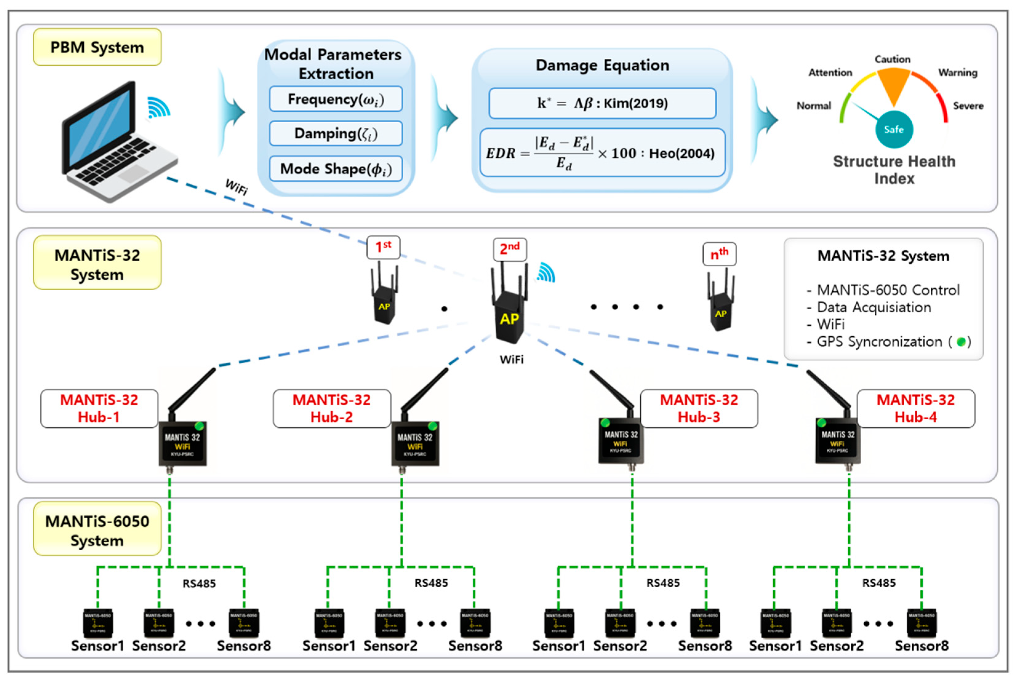
The MANTiS-32 wireless sensing system is engineered to acquire structural response data from MANTiS-6050 sensor units and wirelessly transmit the collected data to a Performance-Based Monitoring (PBM) platform via its integrated access point (AP). The transmitted data are then processed to compute real-time damage indices, enabling continuous assessment of structural integrity and facilitating proactive maintenance strategies. Leveraging a high-performance wireless communication framework, the MANTiS-32 system offers rapid deployment, enhanced scalability, and seamless integration into complex structural configurations. Furthermore, the incorporation of GPS-based time synchronization ensures precise coordination across multiple sensing nodes, thereby supporting accurate, distributed, and synchronized monitoring of structural behavior under dynamic loading conditions. As illustrated in Figure 1, the MANTiS-6050 system is configured by connecting up to eight MPU-6050 sensors (InvenSense Inc., San Jose, CA, USA) to a single MANTiS-32 hub. Each MANTiS-6050 module is equipped with a PIC16 microcontroller, which handles sensor control and data acquisition. The measured data are transmitted to the hub via RS485 communication. A total of four MANTiS-32 units are deployed, each managing eight sensor modules, resulting in a synchronized sensing network composed of 32 individual sensors capable of real-time data acquisition and monitoring.
The sensor data collected by each MANTiS-32 hub is transmitted wirelessly to the Performance-Based Monitoring system via Wi-Fi, utilizing their respective access points (APs). Notably, each MANTiS-32 hub is equipped with a GPS-based time synchronization module, enabling precise temporal alignment of data from distributed sensors. This modular architecture allows for scalable expansion of the sensing network as required by structural monitoring applications. At the top level, the PBM system—implemented as a PC-based analytical platform—performs real-time analysis of the measured vibration data to extract key dynamic characteristics, such as natural frequency (ω), the damping ratio (ζ), and mode shapes (φ). Using established damage detection equations (e.g., Kim, 2019 [24]; Heo, 2004 [25]), the system evaluates changes in structural performance and estimates the progression of damage through a computed Structural Health Index (SHI). This information can then be utilized to support data-driven maintenance and decision-making processes for bridge infrastructure.
Each of the aforementioned modules will be described in detail in Section 2.2 and Section 2.3.

2.2. Design and Operation of the MPU-6050 Sensor Module

As depicted in Figure 2, the MPU-6050 sensors affixed to the structure are designed to continuously capture real-time vibration data. These signals are acquired via an I2C interface by the onboard PIC16F15344 microcontroller (Microchip Technology Inc., Chandler, AZ, USA), which subsequently encodes the data using the RS485 communication protocol for robust transmission to the MANTiS-32 hub. The transmitted data are then relayed wirelessly to the PBM system through Wi-Fi communication. To ensure high-precision temporal alignment across all sensor nodes, the system integrates GPS-based time synchronization. This synchronization capability significantly enhances the accuracy of data correlation, thereby enabling precise identification of structural dynamic characteristics and supporting high-fidelity, real-time SHM of the target infrastructure.
The MPU-6050 sensor’s measurement range was configured to ±2 g, optimized for capturing ambient vibrations typically exhibited by in-service bridge structures. This range selection was based on empirical observations of operational vibration amplitudes, ensuring sufficient resolution and sensitivity for structural health monitoring under service-level conditions. Furthermore, the sensor’s integrated FIFO buffer, with a maximum capacity of 1024 bytes, enables efficient block-based data acquisition and transmission. This design facilitates precise temporal synchronization across multiple sensor nodes, thereby improving data integrity and the overall performance of the wireless sensing network.

2.3. MANTiS-32 Wireless Networking Architecture

MANTiS-32 serves as a wireless data aggregation hub, designed to collect structural vibration data from distributed MANTiS-6050 sensor (InvenSense Inc., San Jose, CA, USA) modules and transmit the acquired signals to a centralized PBM system via Wi-Fi communication. Engineered as a high-fidelity dynamic measurement platform with robust wireless capabilities, MANTiS-32 is optimized for real-time structural condition assessment and modal parameter identification. Its modular design ensures ease of deployment and scalability, enabling flexible integration across a wide spectrum of SHM applications, including small- to medium-span bridges, structural test specimens, and industrial plant systems.
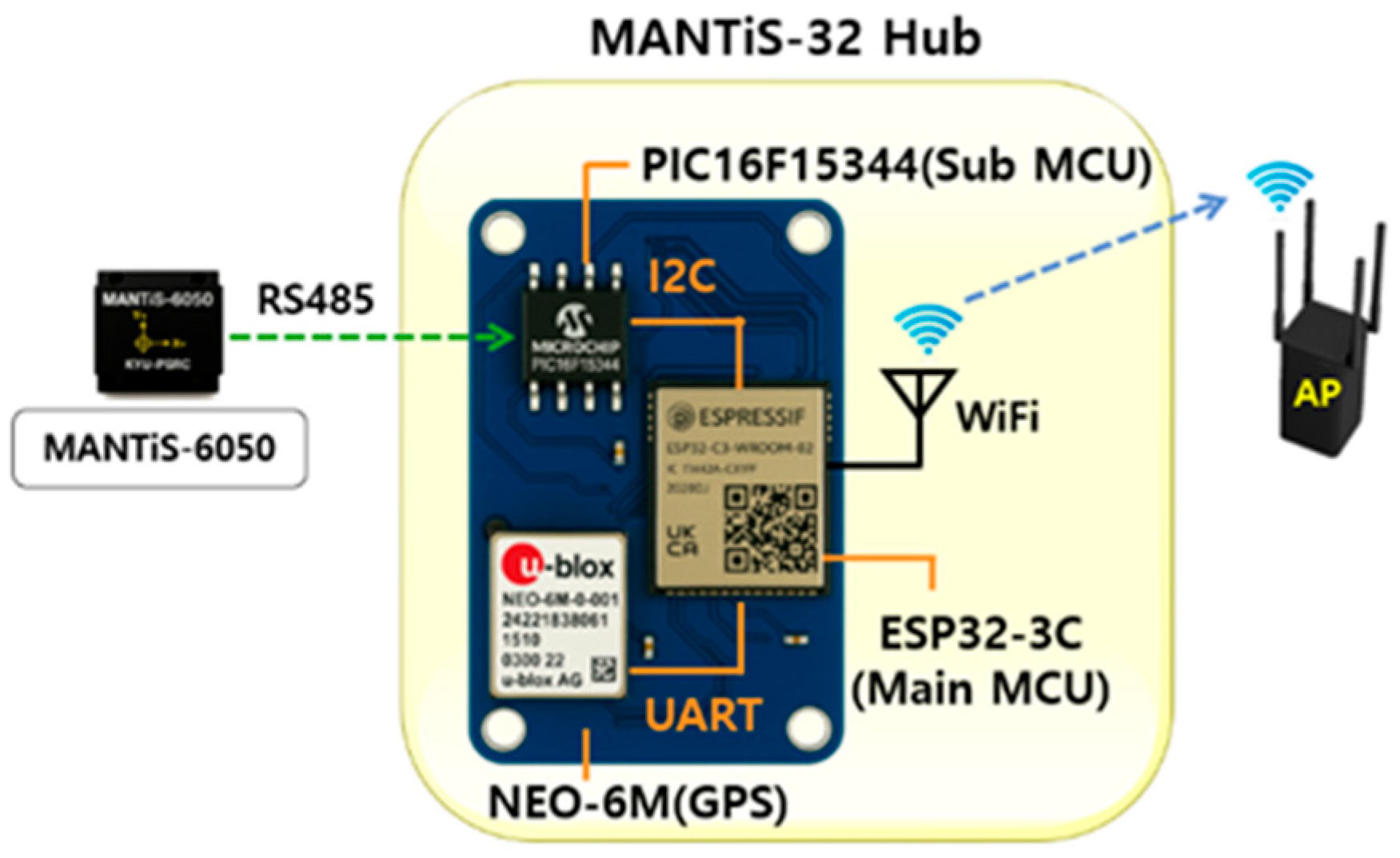
As illustrated in Figure 3, MANTiS-32 is configured to receive data from up to eight MANTiS-6050 sensor (InvenSense Inc., San Jose, CA, USA) nodes via RS485 communication, managed by an onboard PIC16F15344 microcontroller (Microchip Technology Inc., Chandler, AZ, USA). Inter-component communication within the system is established using the I2C protocol, allowing seamless coordination between sensor modules and the ESP32-C3 microcontroller (Espressif Systems, Shanghai, China) for signal processing and configuration control.
To enable high-precision temporal synchronization among multiple hubs and sensor nodes, the system incorporates a NEO-6M GPS module. This module communicates with the ESP32-C3 microcontroller through an interface, providing Real-time Location (UART) and time data. The integration of GPS-based timestamping facilitates accurate alignment of distributed sensor data, thereby enhancing the reliability of time-domain correlation and improving the fidelity of subsequent modal analysis. Wireless data transmission is executed by the ESP32-C3 microcontroller, which communicates with the PBM system through a designated AP using Wi-Fi. This architecture supports synchronized, high-throughput, and low-latency data transfer, forming a comprehensive and scalable framework for real-time wireless structural health monitoring.

2.3.1. Wireless Communication Architecture of the MANTiS-32 Sensing System with MANTiS-6050 Modules

The MANTiS-32 wireless sensing system adopts a hybrid tree-bus topology to achieve enhanced scalability, flexibility, and communication reliability across the sensor network. By synchronizing precise timestamps with each MANTiS-6050 sensor, the system enables orderly, sequential data transmission from each channel. This ensures deterministic communication over the RS485 bus, eliminating data collisions and maintaining high temporal fidelity. As shown in Figure 4, the MANTiS-32 hub is architected to poll data from eight MANTiS-6050 sensor modules at fixed intervals of 0.52 ms. Each sensor’s response is acknowledged before the hub proceeds to the next node, and the aggregated data are subsequently transmitted to the upper-tier PBM system via Wi-Fi. This tightly coordinated, multi-node communication scheme enables highly stable, high-resolution structural monitoring. With a complete sensor sweep across all eight channels achievable in under 4 ms, the system is particularly well-suited for high-frequency vibration measurement and real-time modal analysis.
Each MANTiS-6050 sensor is connected to the MANTiS-32 hub via an RS485 bus, as depicted in Figure 4. Sensor 1 initiates data transmission immediately without delay. Each packet includes a metadata-enriched header comprising the Packet Number (P), Sensor Number (S), and Channel Number (C), followed by sensor measurements encoded in ASCII-format hexadecimal values. Upon completion of transmission, the appearance of a semicolon (;) on the RS485 line is interpreted as the end-of-packet delimiter. This triggers a fixed latency of 0.52 ms before the next sensor node initiates transmission. This time-slotted, collision-free communication strategy ensures orderly access to the shared RS485 bus, facilitating precise time alignment and efficient high-throughput data acquisition across the sensor array.

2.3.2. Communication Between the MANTiS-32 Hub and AP

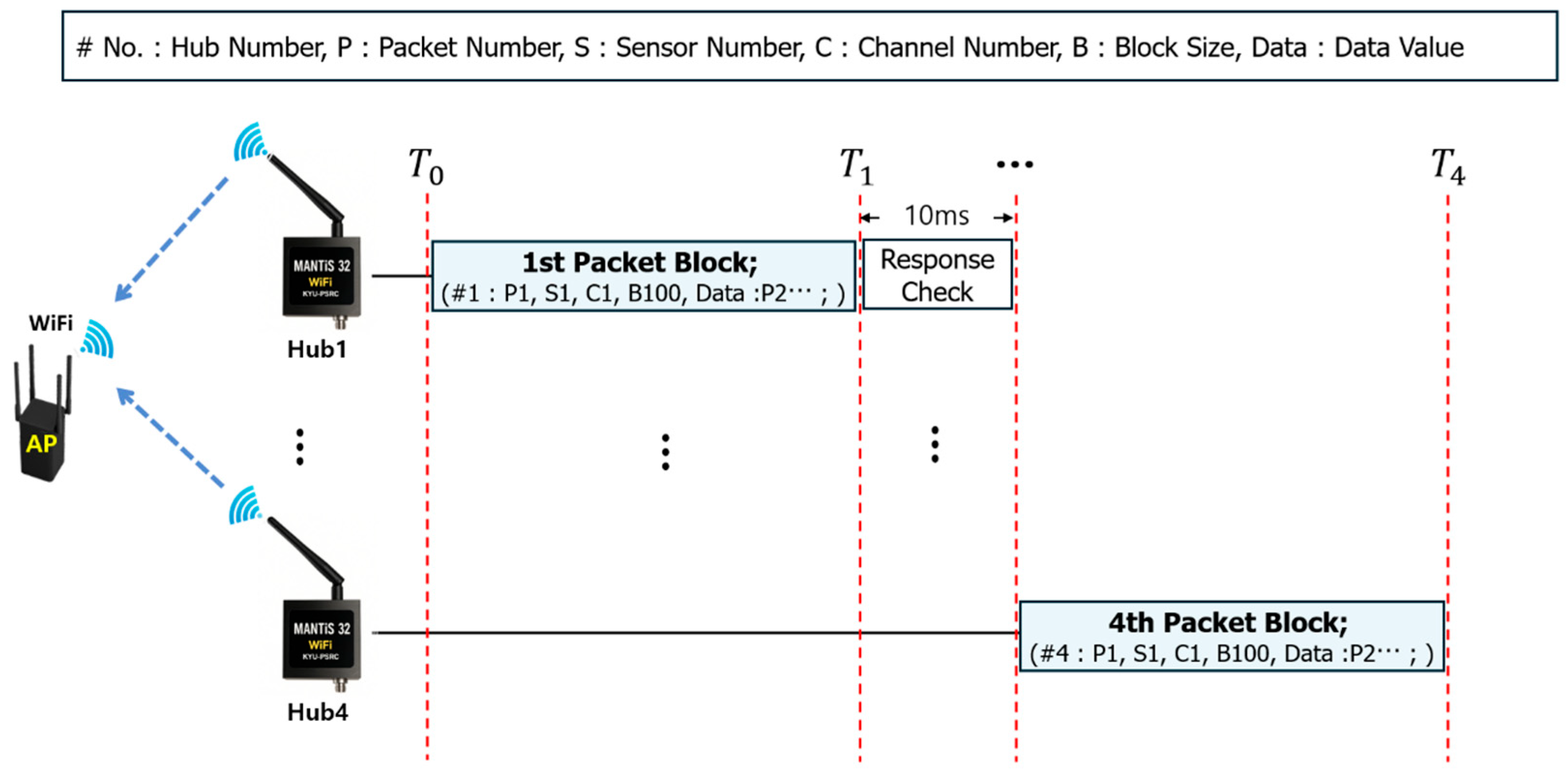
The communication architecture between the MANTiS-32 hub and the AP is implemented using a hierarchical tree topology over Wi-Fi, enabling scalable and structured data aggregation from distributed sensing units. Each MANTiS-32 hub collects vibration data packets from its connected MANTiS-6050 sensor nodes and assembles them into predefined packet blocks for transmission. As illustrated in Figure 5, each packet block consists of a header containing key metadata—such as Hub Number (#), Packet Number (P), and Block Size (B)—followed by the sensor data payload. Sensor readings are encoded in hexadecimal ASCII format and delimited by a colon (:) to ensure clear separation and traceability.
Data transmission is performed sequentially on a per-block basis. For example, once Hub #1 initiates its transmission without delay, subsequent hubs monitor the RS485 or Wi-Fi network for a terminal semicolon (;) indicating the end of the preceding packet block. Upon detection, they introduce a fixed 10 ms delay before commencing their own transmissions. During this interval, each hub performs a brief wireless channel assessment to avoid collisions, ensuring reliable and orderly communication even under intermittent network instability. This time-synchronized, block-based transmission strategy ensures that sensor data from multiple hubs is delivered without overlaps, maintaining both temporal coherence and high data fidelity. The sequential protocol not only mitigates data loss and transmission conflict but also supports scalable expansion across a wide range of monitoring environments.
The MANTiS-32 system is architected as a high-performance, wireless SHM network, specifically tailored for deployment in spatially distributed infrastructure, such as long-span bridges, high-rise buildings, and industrial facilities. In such applications, multiple MANTiS-32 hubs can be deployed across key structural zones, each wirelessly transmitting synchronized, high-resolution sensor data to a centralized AP. This configuration enables the accurate reconstruction of global dynamic behavior (including mode shapes and natural frequencies) in a time-aligned manner, thereby supporting real-time damage detection and early-warning capabilities essential for condition-based maintenance and operational safety.

3. Validation of MANTiS-32 Sensing Performance

3.1. Calibration and Accuracy Assessment of the MANTiS-6050 Sensor

MANTiS-6050 is a digital inertial sensor that outputs raw acceleration data obtained via analog-to-digital (A/D) conversion, which must be transformed into physical units of gravitational acceleration (g) for engineering applications. This section outlines the calibration procedure used to convert digital signals into calibrated acceleration values and presents an experimental evaluation of the sensor’s measurement accuracy following calibration.

3.1.1. Calibration of the MANTiS-6050 Sensor

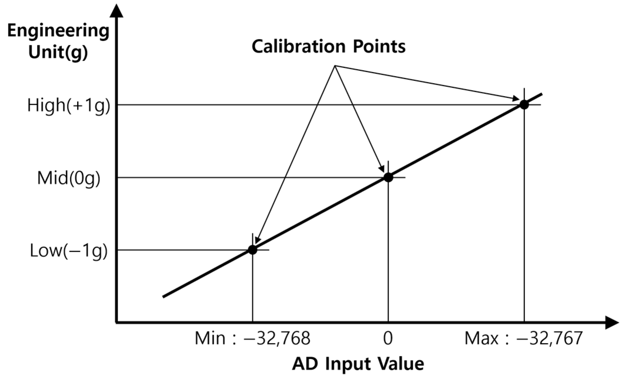
The MANTiS-6050 sensor outputs acceleration measurements internally in 16-bit signed integer format, spanning a range from −32,768 to +32,767. Under ideal conditions, this digital output is assumed to exhibit a linear correspondence with gravitational acceleration within the range of −1 g to +1 g, such that −32,768 maps to −1 g, +32,767 to +1 g, and 0 to 0 g. However, due to inherent variations in the manufacturing process and external environmental factors, the raw sensor output is susceptible to zero bias and sensitivity drift, necessitating a robust calibration procedure to ensure accurate translation into physical units. To compensate for these deviations, a three-point calibration method was applied, as depicted in Figure 6.
This method involves positioning the sensor at three reference orientations corresponding to known static acceleration levels: −1 g (Low), 0 g (Mid), and +1 g (High). By capturing the sensor’s digital output at each of these calibration points, a linear mapping is established between the raw A/D values and the actual gravitational acceleration. This mapping allows for precise correction of both offset and sensitivity errors.
Following the application of this calibration procedure, the MANTiS-6050 sensor is capable of delivering accurate acceleration measurements in units of g, as further validated through empirical testing presented in Section 3.1.2.

3.1.2. Verification of Output Accuracy for the MANTiS-6050 Sensor

To verify the accuracy of the calibrated MANTiS-6050 sensor, a series of static tests were conducted under non-accelerated conditions. In the absence of external excitation, the sensor is expected to exhibit only intrinsic white noise, characterized by low-magnitude fluctuations. Under proper calibration, the axis aligned with the gravitational field should register a value close to 1 g with minimal white noise, while the orthogonal axes should remain centered around 0 g within similar noise bounds. As depicted in Figure 7a, the sensor was mounted on the shaker table of an electrodynamic vibration test system, with the x-, y-, and z-axes sequentially aligned along the vertical (gravitational) direction. Each configuration was maintained for 100 s to collect sufficient data for validation.
As shown in Figure 7b, when each axis was oriented in the gravitational direction, the corresponding output consistently measured approximately 1 g, with only negligible white noise. The remaining two axes, perpendicular to gravity, exhibited near-zero outputs, also within expected noise levels. These results confirm the effectiveness of the three-point calibration process and validate the MANTiS-6050 sensor’s capability to produce accurate and stable acceleration measurements under static conditions.

3.2. Evaluation of Measurement Performance of the MANTiS-6050 Sensor

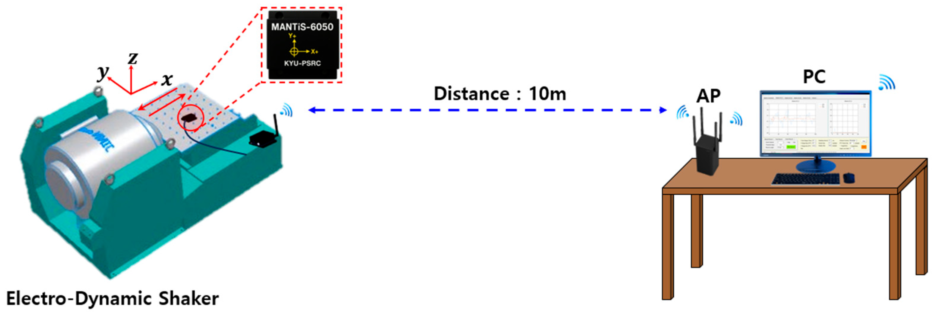
To validate the acceleration measurement accuracy of the MANTiS-6050 sensor, a series of controlled excitation tests were performed using an electrodynamic shaker system (Sonic Dynamics Inc., Suzhou, China). In this experimental setup, known input vibrations were applied to the sensor, and the measured responses were compared against the excitation signals to assess the sensor’s fidelity and precision. As illustrated in Figure 8, the test configuration included the MANTiS-6050 sensor module interfaced with the MANTiS-32 wireless communication unit, both mounted on the shaker table. A wireless repeater and an access point (A3004T, ipTIME; 2.4 GHz Wi-Fi) were positioned 10 m from the setup to establish a real-time data transmission environment representative of field conditions. The excitation frequencies were selected within the range of 5 Hz to 20 Hz, corresponding to the typical fundamental frequencies of small- to medium-span bridge structures. Based on the Nyquist sampling criterion and to enhance spectral resolution, the sampling rate was set to 100 Hz, equivalent to five times the highest input frequency. Real-time acceleration data were collected over 60 s intervals for each test condition.
The input amplitude was incrementally increased from 0.1 g, in steps of 0.1 g, while the input frequency varied from 5 Hz, in 0.5 Hz increments. These excitations were applied sequentially to the x-, y-, and z-axes across sensors #1 through #6. The corresponding measured signals were then compared with the input references, and the results are summarized in Table 2. As reported in Table 2, the average error in amplitude measurements was found to be 0.91%, while the average deviation in frequency was 0.40%. These results indicate that the MANTiS-6050 sensor maintained high measurement fidelity, with both amplitude and frequency errors consistently within 1%. Such performance demonstrates the sensor’s strong potential for reliable acceleration monitoring in structural health applications, particularly in small- to medium-scale bridge systems.

3.3. Wireless Communication Performance Assessment of the MANTiS-32 System

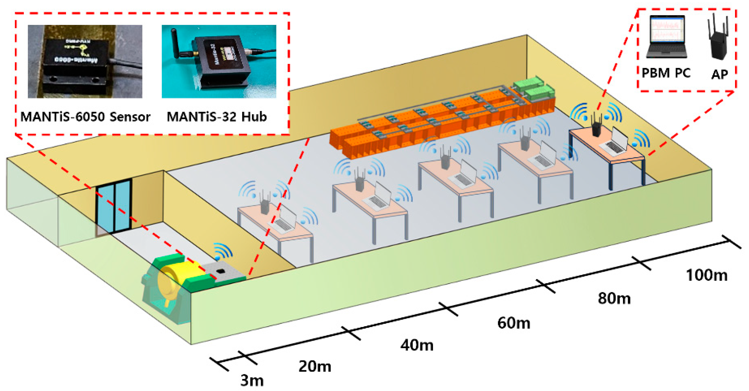
In wireless structural monitoring systems, communication range and transmission stability are key determinants of data reliability. Civil infrastructure, such as bridges, often exists in environments where unforeseen physical obstructions can disrupt signal paths, resulting in data degradation. To ensure accurate and continuous monitoring of structural behavior, especially under high-frequency sampling conditions, the wireless system must maintain consistent and robust communication performance. The MANTiS-32 system was designed to operate over the 2.4 GHz Wi-Fi band, with the specific objective of sustaining reliable data transmission even in obstructed or partially enclosed environments. This capability is particularly critical for field applications, where environmental variability and structural complexity pose significant challenges to long-range wireless communication. To evaluate the system’s communication performance, a series of experiments were conducted to assess the transmission range, received signal strength, and data acquisition rate under various sampling frequencies. As illustrated in Figure 9, the distance between the MANTiS-6050 sensor module and the MANTiS-32 unit was incrementally increased from 20 m to 100 m, in steps of 20 m. A 3 dBi external antenna was employed to support signal propagation, and excitation was applied using an electrodynamic shaker, as shown on the left side of Figure 9. To simulate a realistic obstructed environment, a temporary partition wall was installed between the MANTiS-32 hub and the access point (AP), creating a semi-enclosed space representative of field conditions. This setup was intended to verify the MANTiS-32’s ability to maintain high-fidelity wireless data transmission under shielded environment conditions, further validating its applicability to complex civil infrastructure monitoring scenarios.
At each measurement point, the Received Signal Strength Indicator (RSSI) was measured ten times, and the average signal strength was computed using Equation (1). To further evaluate communication performance, the sampling frequency was systematically increased to 20 Hz, 50 Hz, 100 Hz, and 200 Hz at each distance interval. The data acquisition rate was quantified by calculating the proportion of successfully received data relative to the total transmitted data, thereby assessing transmission reliability as a function of both distance and sampling frequency.
S i g n a l   S t r e n g t h % = R S S I a v e r a g e R S S I m i n R S S I m a x R S S I m i n × 100
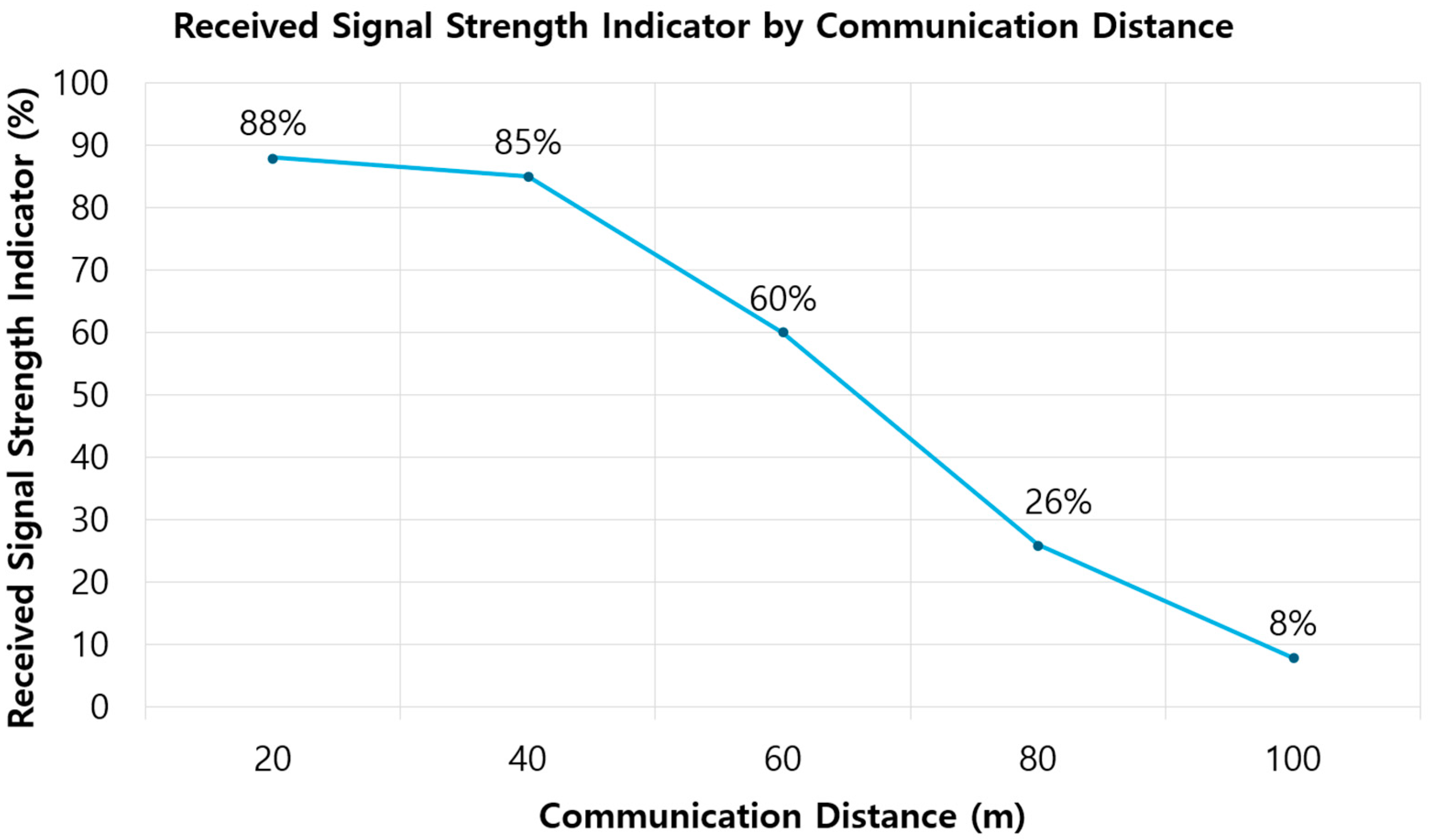
Here, R S S I a v e r a g e denotes the average value of the 10 measurements conducted under identical conditions, while R S S I m i n and R S S I m a x represent the minimum and maximum values observed, respectively. As summarized in Table 3, the measured signal strength remained above 80% at up to a distance of 40 m, with average RSSI values of 88% at 20 m and 85% at 40 m (Figure 10). However, beyond this range, a notable decline was observed: the signal strength dropped to 60% at 60 m and further to 26% at 80 m. Despite this degradation, the data acquisition rate was largely unaffected, as shown in Table 3, indicating that the system maintained stable data transmission at up to 80 m. At 100 m, however, the RSSI sharply declined to 8%, resulting in a complete failure to acquire data (0% acquisition rate). This limitation is likely attributable to the performance constraints of the 3 dBi antenna used in the test. Therefore, to extend the effective communication range, the use of higher-gain antennas, such as 6 dBi or 9 dBi models, is recommended. These alternatives are expected to enhance signal propagation and improve long-distance communication performance in field deployments.
Moreover, since the data acquisition rate is strongly influenced by both communication distance and sampling frequency, the results summarized in Table 4 demonstrate that even when the transmission distance was extended from 20 m to 80 m and the sampling frequency increased from 20 Hz to up to 200 Hz, the system maintained 100% data acquisition with no observed packet loss. This indicates that the MANTiS-32 system is capable of stable and lossless data transmission under varying sampling conditions within this range. However, at a transmission distance of 100 m, where the Received Signal Strength Indicator (RSSI) declined sharply to approximately 8%, the system failed to acquire valid data, resulting in a 0% acquisition rate. This outcome highlights the critical threshold below which wireless signal degradation compromises reliable data collection, emphasizing the importance of maintaining sufficient signal strength for long-range monitoring applications.
The results of this experiment demonstrate that reliable wireless communication and consistent data acquisition were maintained at up to 80 m, even within an indoor environment designed to simulate obstructed conditions. These findings suggest that the validated communication range is more than adequate to support structural monitoring operations on small- to medium-span bridges under comparable field conditions.

3.4. Integrated Measurement Performance Evaluation of the MANTiS-6050 Sensor and MANTiS-32 System

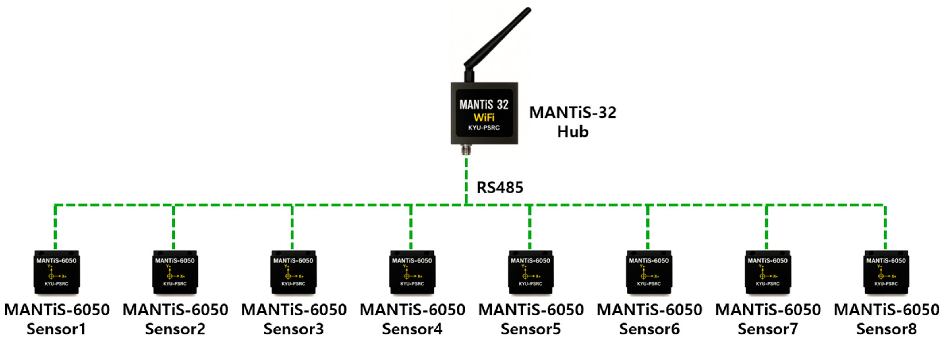
The MANTiS-32 system is designed to interface with up to eight MANTiS-6050 sensor modules, as illustrated in Figure 11. When all eight sensors are simultaneously connected, their measurement data are transmitted through a single MANTiS-32 hub, which may introduce a communication bottleneck. Such a bottleneck can lead to data loss or transmission delays, thereby compromising the reliability of the acquired data.
This experiment aimed to verify whether measurement data from all eight MANTiS-6050 sensors could be transmitted reliably and without loss from the MANTiS-32 hub to the PBM system. Considering that the MANTiS-32 platform was designed primarily for monitoring real bridge structures with dominant frequencies below 100 Hz, in accordance with the Nyquist–Shannon sampling theorem, the system’s performance was validated at up to a maximum sampling rate of 200 Hz.

3.4.1. Test Structure for System Validation

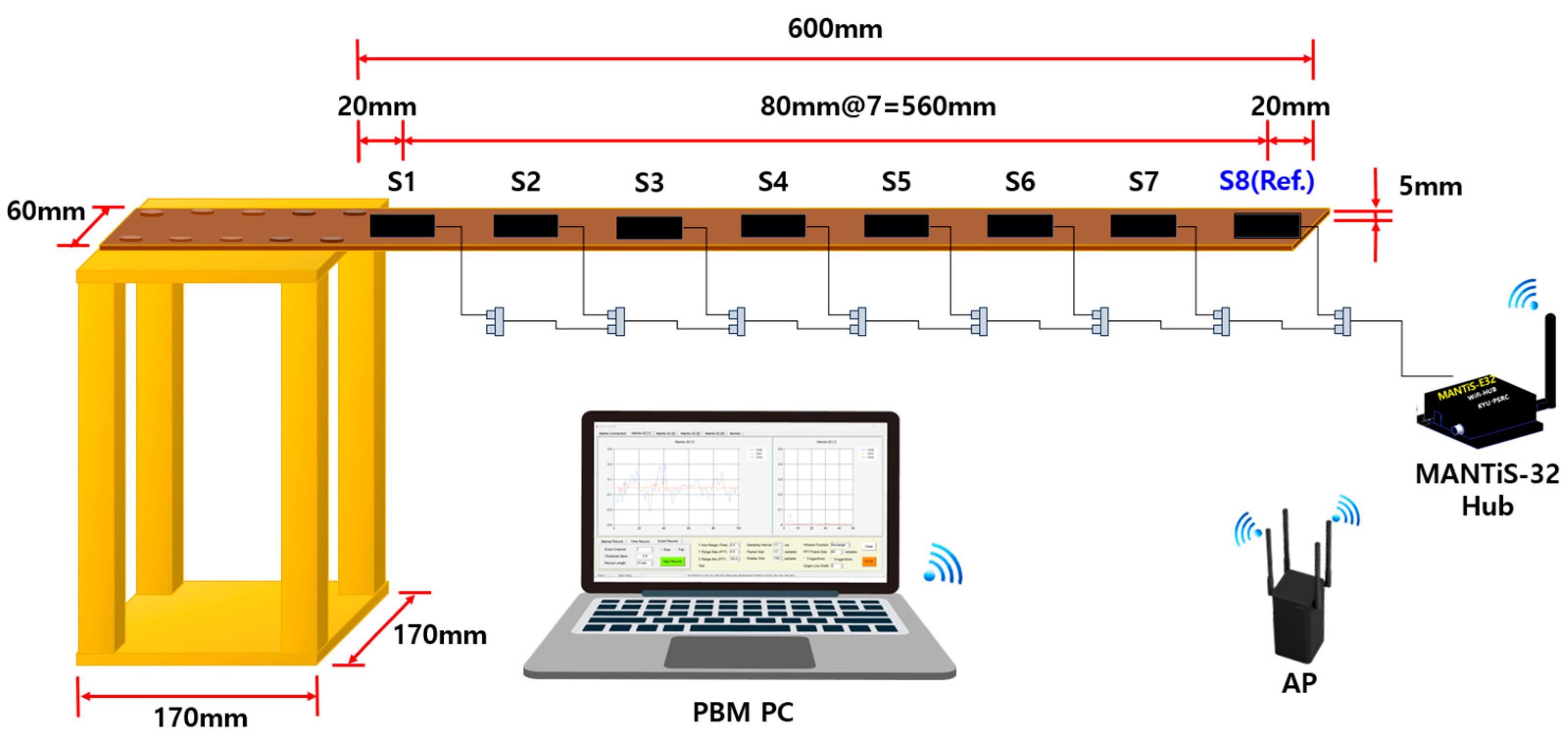
To validate the measurement capability of the system on relatively flexible structural elements, a simple cantilever beam specimen was selected, as depicted in Figure 12. The beam was fabricated from standard structural steel, with dimensions of 770 mm in length, 60 mm in width, and 5 mm in thickness. The mechanical properties of the material are presented in Table 5. The geometric configuration of the test structure and the spatial arrangement of the sensors for the MANTiS-32 measurement experiment are shown in Figure 12.

3.4.2. FE-Based Modal Characterization of the Cantilever Beam for MANTiS-32 Performance Verification

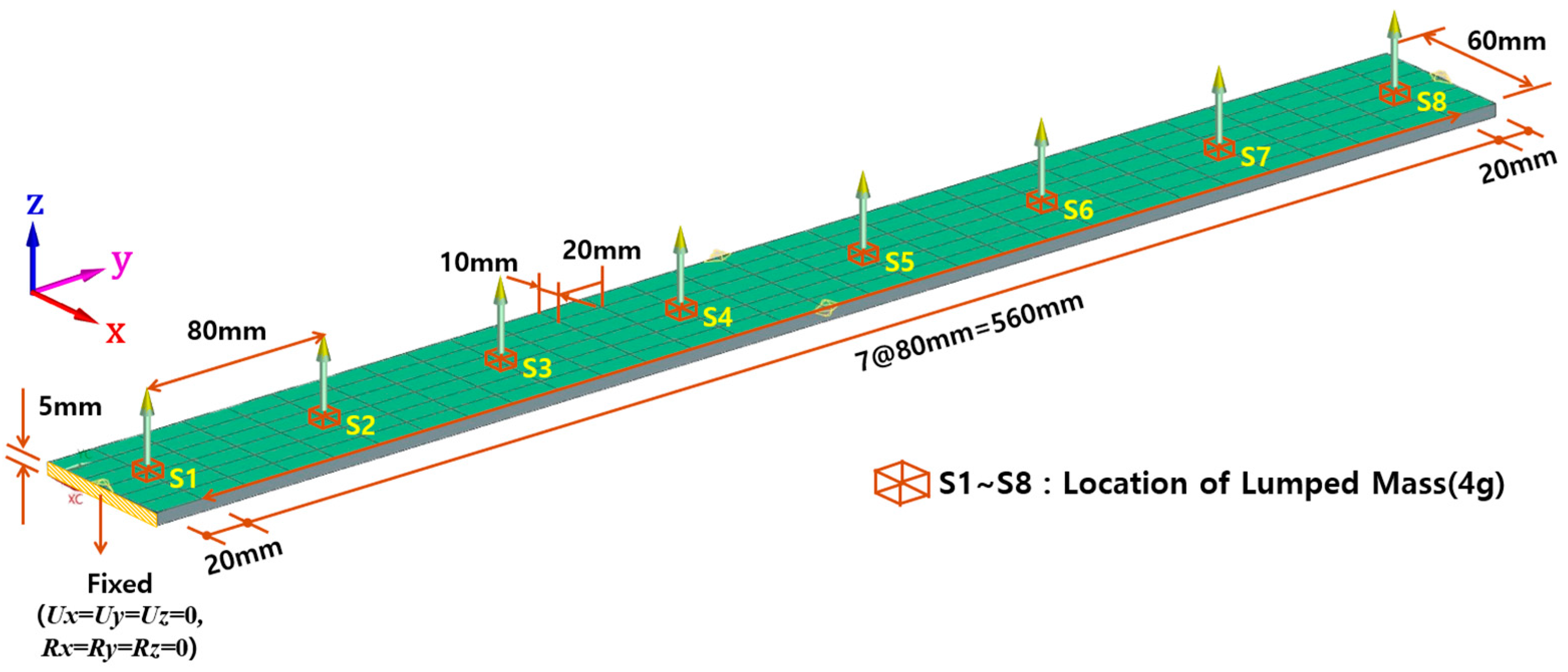
To evaluate the sensing performance of the MANTiS-32 wireless measurement module, an FE analysis was conducted to characterize the dynamic behavior of the cantilever beam. Modal analysis was carried out using SIEMENS NX integrated with the NASTRAN solver, utilizing CQUAD4 quadrilateral shell elements, as illustrated in Figure 13. The beam model was discretized into 180 elements and 217 nodes, with eight nodes strategically selected to correspond exactly to the physical sensor locations on the test specimen. This spatial alignment facilitated a direct one-to-one comparison between the experimental measurements and the numerical simulation results, thereby enabling a rigorous validation of the system’s dynamic response accuracy.
The cantilever beam was modeled with its left end fully constrained in the x–y plane, representing the fixed support, while the right end remained free, allowing unrestricted vertical vibrations along the z-axis. Given the lightweight nature of the beam, the influence of the relatively heavier MANTiS-6050 sensors was non-negligible. To accurately replicate the physical testing conditions, lumped masses of 4 g corresponding to the mass of each sensor were applied at eight discrete locations (S1 through S8), as indicated in Figure 13. Incorporating these mass effects, the finite element modal analysis yielded a first natural frequency of 8.445 Hz and a second natural frequency of 53.024 Hz, providing a reliable dynamic baseline for comparison with the experimental measurements.

3.4.3. Modal Sensing Performance Evaluation of MANTiS-32

To assess the modal sensing performance of the MANTiS-32 wireless measurement module, eight MANTiS-6050 accelerometers were uniformly mounted along the top surface of the cantilever beam at intervals of 80 mm, as shown in Figure 12. Each sensor was connected to a single MANTiS-32 hub via RS485 communication, and the acquired data were transmitted in real time to the PBM system through a Wi-Fi access point. The sampling frequency for all sensors was set to 200 Hz, and data were recorded continuously for a duration of 16 s. An impulse load was applied to induce free vibration in the beam, and the resulting acceleration responses were used for output-only ambient modal analysis. The analysis was performed using the Time Domain Decomposition (TDD) technique, following the method proposed by Kim et al. (2005) [26], enabling real-time identification of modal parameters. As representative results, Figure 14a presents the acceleration response measured at sensor location S8, while Figure 14b illustrates the corresponding cross-correlation function. The power spectral density of the signal, shown in Figure 14c, clearly reveals the beam’s dominant natural frequencies, with the first and second modes identified at 8.406 Hz and 53.864 Hz, respectively. These results closely align with the finite element predictions, confirming the reliability of the MANTiS-32 system for accurate wireless modal sensing.

3.4.4. Assessment of Measurement Accuracy in the MANTiS-32 Wireless Module

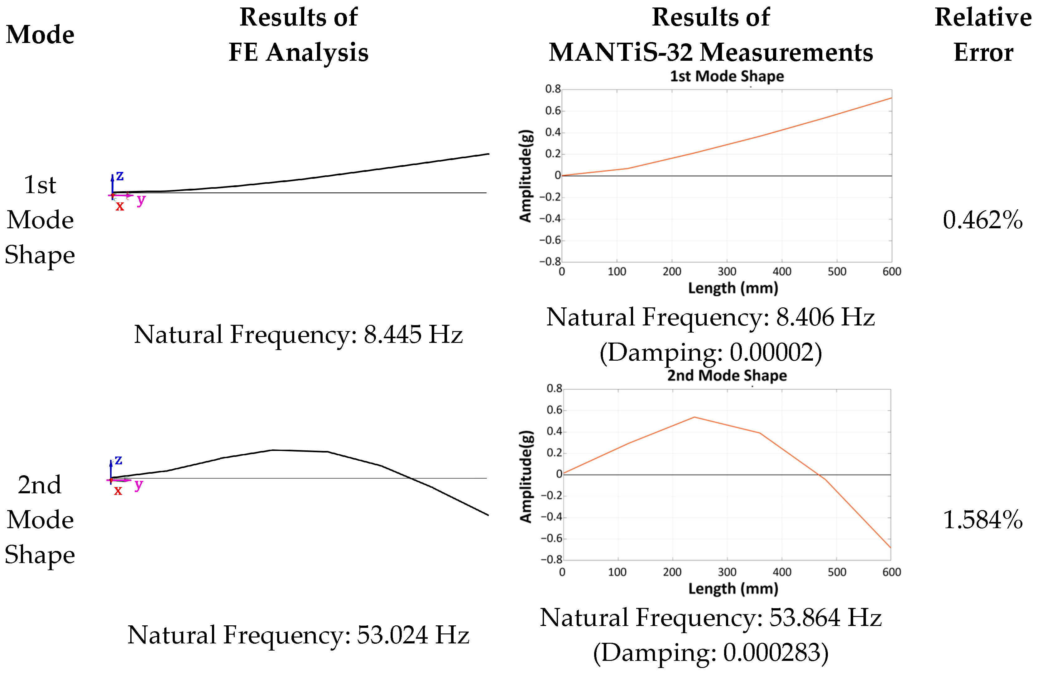
With all eight MANTiS-6050 sensors operating concurrently and connected to a single MANTiS-32 module, the system demonstrated stable and uninterrupted signal acquisition, with no observable time delays or communication bottlenecks. This enabled seamless execution of real-time modal analysis for the cantilever beam without any degradation in data quality or transmission performance. The experimentally obtained dynamic characteristics were then compared to those derived from the FE model, as illustrated in Figure 15. Both the mode shapes and corresponding natural frequencies were accurately identified. The deviation between the measured and simulated results was minimal, with the first natural frequency exhibiting a relative error of 0.462% and the second a deviation of 1.584%. These results validate the precision and robustness of the MANTiS-32 system in performing wireless modal sensing, confirming its suitability for real-time structural health monitoring applications.
Both the first and second mode shapes were identified as bending modes, exhibiting qualitative agreement between the finite element analysis and experimental results. To quantitatively assess the level of agreement, a Modal Assurance Criterion (MAC) analysis was performed using Equation (2).
M A C ( i , j ) = ϕ i T ψ j 2 ϕ i T ϕ i ψ j T ψ j
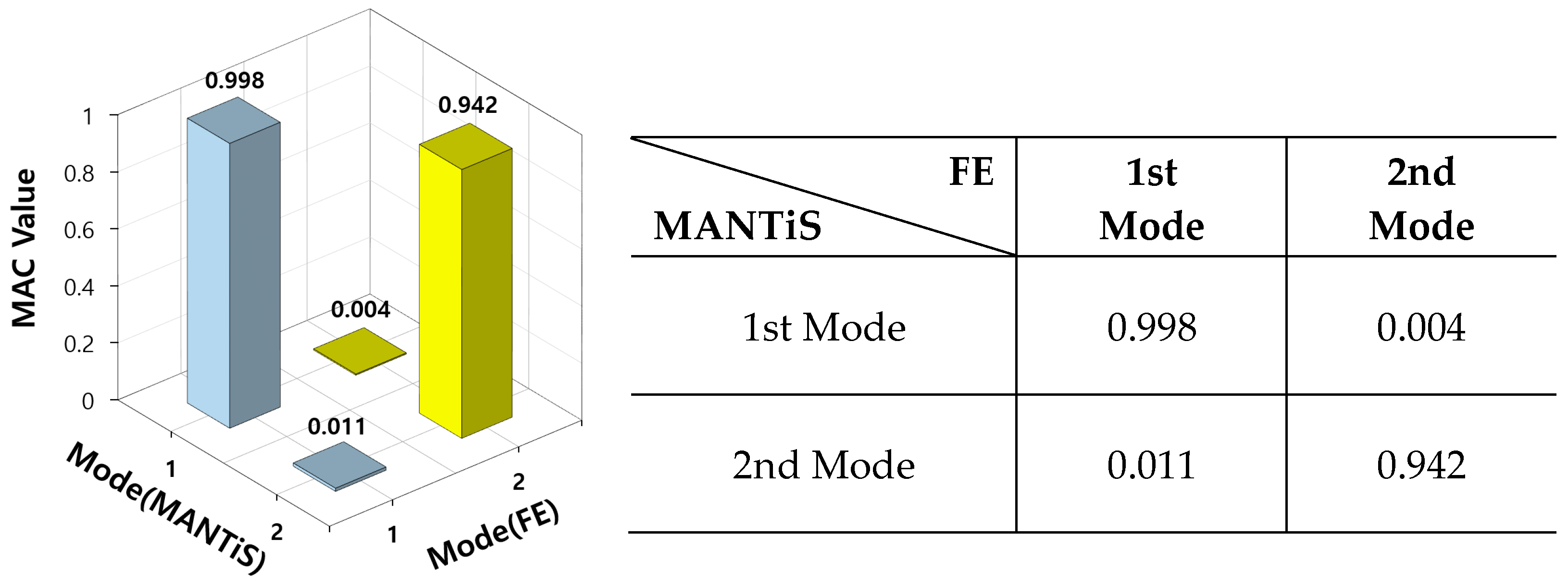
Here, ϕ i represents the i-th mode shape vector obtained from the finite element analysis, while ψ j denotes the j-th mode shape vector extracted from the multi-sensor experimental measurements. As shown in Figure 16, the MAC analysis yielded a correlation exceeding 99.9%, indicating excellent agreement between the simulated and measured mode shapes. This result confirms the high accuracy and reliability of the MANTiS-32 system and the connected MANTiS-6050 sensors in capturing dynamic structural responses.
These findings confirm that the MANTiS-32 wireless sensing module, operating in conjunction with eight simultaneously connected MANTiS-6050 sensors, is capable of conducting stable, interference-free measurements. The system demonstrated outstanding performance in capturing structural modal characteristics, thereby validating its effectiveness for high-fidelity modal sensing applications.

4. Multi-Module Measurement Validation of MANTiS-32

As shown in Figure 17, the MANTiS-32 system is designed to transmit measurement data from four independently operating modules, each interfaced with eight MANTiS-6050 sensors to a centralized PBM system via a common wireless AP.
Each MANTiS-32 unit is equipped with an integrated NEO-6M GPS module, enabling precise time synchronization across all four modules and their respective sets of eight connected sensors. The synchronized acceleration data from all 32 sensor nodes are transmitted in real time to the main PBM computer via a wireless AP, where they are sequentially received and stored. These time-aligned measurements are then used to perform real-time modal analysis of a scaled cable-stayed bridge model, facilitating the extraction of critical modal parameters, such as natural frequencies, mode shapes, and damping ratios. The analysis results support performance-based structural health monitoring and inform maintenance decision-making. This section validates the measurement performance of the MANTiS-32 wireless sensing system by demonstrating its capability to reliably acquire synchronized data from multiple distributed modules and to perform accurate, real-time modal identification of the test structure.

4.1. Evaluation of Modal Analysis Performance Using a Scaled Cable-Stayed Bridge Model

To evaluate the sensing performance of the MANTiS-32 wireless monitoring system, a 1:30-scaled replica of the Dolsan Bridge, which is an operational cable-stayed bridge located in Yeosu, South Korea, was constructed. To simulate the flexibility of small- to medium-span bridges, additional lumped masses were incorporated to reduce the model’s natural frequency to below 10 Hz.

4.1.1. Design and Construction of the Scaled Bridge Model

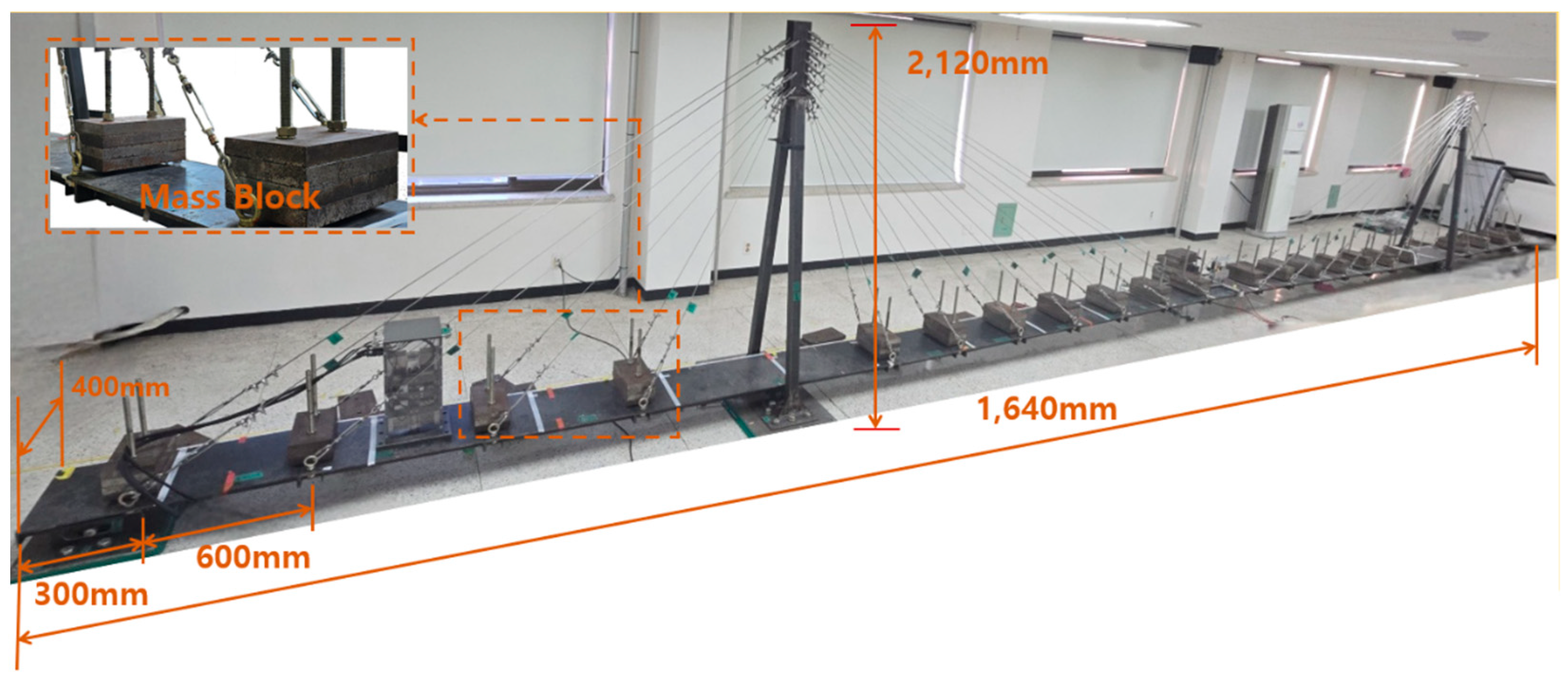
The full-scale prototype is a three-span, continuous steel-box girder cable-stayed bridge with a total length of 450 m, a width of 11.7 m, and a pylon height of 62 m. The scaled model, shown in Figure 18, was fabricated at a 1:30 geometric scale, resulting in a total length of 1640 mm, a pylon height of 2120 mm, and a deck width of 400 mm. To ensure that the model accurately reflects the dynamic behavior of a flexible, small- to medium-span bridge, structural stiffness was deliberately minimized, and additional mass blocks were installed on the deck, as illustrated in Figure 18, to lower the fundamental frequency.
The scaled cable-stayed bridge model was constructed using conventional structural steel, with material properties summarized in Table 6. The total mass of the deck-mounted lumped masses is 1480 kg. The steel exhibits a Poisson’s ratio of 0.30, a shear strength of 40 kgf/mm2, and a Young’s modulus of 2.15 × 10⁴ kgf/mm2, ensuring appropriate stiffness and mass distribution for simulating the dynamic behavior of a medium-span bridge.

4.1.2. Finite Element Modal Analysis of the Scaled Cable-Stayed Bridge Model

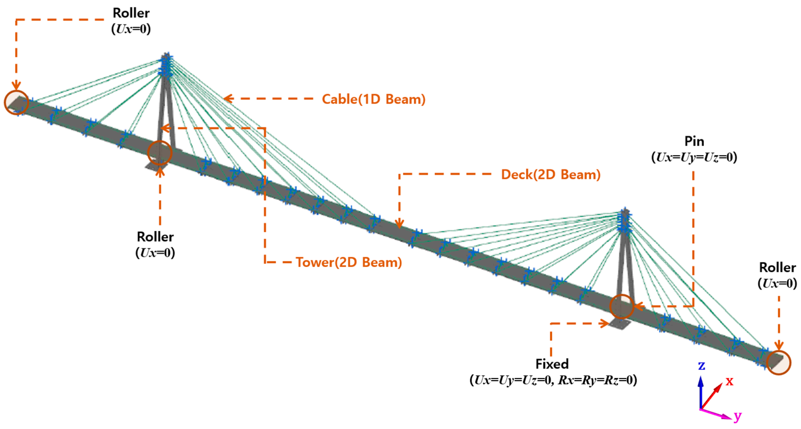
The dynamic characteristics of the scaled cable-stayed bridge model were analyzed using a finite element approach. Structural modeling was conducted in SIEMENS NX, and modal analysis was performed using the NASTRAN Normal Mode Dynamic Solver. As illustrated in Figure 19, the model was divided into key structural components (deck, pylons, cables, and lumped masses) to reflect the actual mechanical behavior of the bridge. The deck and pylons were modeled with two-dimensional beam elements, while the cables were represented using one-dimensional tension-only elements. Boundary conditions at the deck supports were simulated using rigid body elements to accurately constrain the model. This detailed FE modeling strategy enabled the precise evaluation of the bridge’s natural frequencies and corresponding mode shapes, forming a foundation for validating the measurement system’s dynamic sensing capabilities.
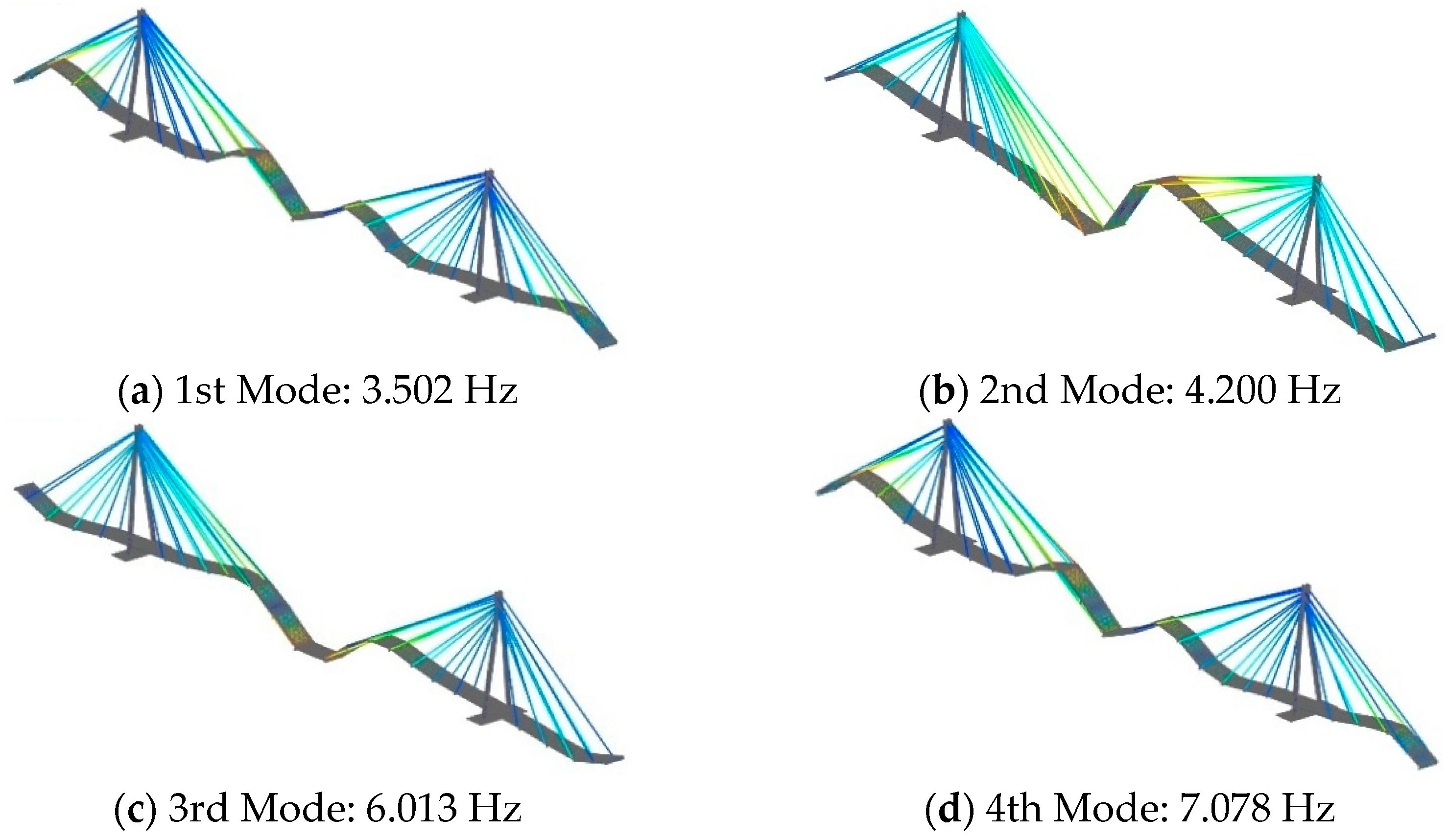
To enhance the dynamic flexibility of the scaled bridge model, twenty-two lumped masses of 40 kg each were placed at specific nodal locations along the central deck girders, excluding the pylon zones and both end spans. These mass additions were intended to replicate the inertial characteristics of a low-stiffness bridge deck. Boundary conditions were defined as follows: the bases of the pylons were fully fixed, while the left pylon and both ends of the deck were constrained with roller supports. The right pylon was connected to the deck via a pinned joint. Furthermore, 36 nodes at the center of the deck were left fully unconstrained in the x, y, and z directions to allow for free translational motion. Finite element modal analysis results demonstrate that, owing to the bridge’s long and slender geometry, the first four vibration modes were dominated by global bending deformations, as shown in Figure 20. The corresponding natural frequencies were calculated as 3.502 Hz (1st mode), 4.200 Hz (2nd mode), 6.013 Hz (3rd mode), and 7.078 Hz (4th mode). All modes fell below the 10 Hz threshold, successfully capturing the dynamic behavior of a flexible, small-to-medium-span cable-stayed bridge.

4.2. Validation of Modal Sensing Performance of the MANTiS-32 System

To rigorously evaluate the modal sensing performance of the MANTiS-32 wireless structural health monitoring system, a total of four MANTiS-32 units and twenty-six MANTiS-6050 accelerometers were deployed on the scaled cable-stayed bridge model. As depicted in Figure 21, twenty-four accelerometers (designated N1 through N12 on the north side and S1 through S12 on the south side) were uniformly distributed along both sides of the bridge deck, excluding 0.6 m from each end. Additionally, two reference sensors were symmetrically installed near the mid-span of the bridge deck to serve as baseline indicators. All sensor nodes were connected to their respective MANTiS-32 hubs and synchronized using integrated GPS modules. The acceleration data were transmitted in real time to a central PBM computer via a wireless AP. Data acquisition was performed continuously for 20 min at a sampling rate of 50 Hz (corresponding to a 10 ms interval), enabling verification of time synchronization among the four hubs and evaluation of potential data transmission bottlenecks. To induce low-amplitude dynamic responses appropriate for output-only modal analysis, ambient vibrations, primarily those generated by human footfalls in the vicinity, were utilized as the excitation source. This experimental setup allowed for a realistic assessment of the system’s ability to capture and transmit synchronized dynamic responses from a distributed sensor network in real time.
Real-time modal analysis was conducted on the ambient vibration data using the Time Domain Decomposition (TDD) technique, as previously demonstrated in Section 3.4.3, following the approach proposed by Kim (2005) [26].
From the measured acceleration time histories, as illustrated in Figure 22a, the cross-correlation functions between sensor signals were computed, as shown in Figure 22b. Subsequently, the Power Spectral Density (PSD) was estimated, as presented in Figure 22c, to identify the dominant frequency bands associated with the structure’s natural modes. Based on the PSD peaks, the first four modal frequencies were determined to be 3.504 Hz, 4.238 Hz, 6.170 Hz, and 7.280 Hz, respectively.
The extracted modal frequencies were identified as 3.504 Hz for the first mode, 4.238 Hz for the second, 6.170 Hz for the third, and 7.280 Hz for the fourth mode (Figure 23). When compared with the results of the FE analysis, the discrepancies were within 1.6%, demonstrating high accuracy. Moreover, all identified mode shapes were consistent with the FE analysis results, exhibiting bending mode characteristics. To quantitatively assess the similarity of the mode shapes, a Modal Assurance Criterion (MAC) analysis, as defined in Equation (2), was conducted, and the results are presented in Figure 24.
The MAC analysis across all identified modes yielded high correlation values ranging from 90% to 99%, confirming strong agreement between the mode shapes obtained from experimental measurements and those derived from the finite element model. These findings validate the capability of the MANTiS-32 wireless sensing system to reliably acquire real-time modal parameters—both eigenvalues and eigenvectors—essential for performance-based damage assessment in PBM systems. The system demonstrated robust multi-sensor synchronization and data transmission without bottlenecks, even under complex structural configurations, affirming its suitability for high-fidelity structural health monitoring of cable-stayed bridge models.

5. Conclusions

This study presents the development and validation of the MANTiS-32 wireless sensing system, a low-cost, high-precision monitoring solution tailored for performance-based maintenance of small- to medium-span bridges. Built upon an open-source platform, the system integrates ESP32 microcontrollers with MPU-6050 inertial sensors and supports real-time data transmission via Wi-Fi communication. Each MANTiS-32 hub is capable of interfacing with up to eight MPU-6050 units, enabling scalable deployment across bridge structures.
Initial validation confirmed the system’s fundamental sensing capabilities, including accurate acceleration measurements under both impulse loads and ambient excitations, such as human footsteps. The MANTiS-6050 sensors demonstrated sufficient sensitivity for dynamic response capture, and the MANTiS-32 hub processed and transmitted the data with no observable latency or signal bottlenecks.
Wireless communication between MANTiS-32 hubs and the access point was executed using predefined packet blocks, effectively mitigating synchronization issues. Reliable data acquisition was achieved in real time, even when concurrently streaming from 26 distributed sensors across four hubs. The system maintained stable performance at up to an 80 m communication range, and the potential for further extension was verified by the scalable use of additional APs.
To assess the system’s capability in real-world applications, a 1:30-scale model of a cable-stayed bridge was instrumented with 26 sensors for real-time ambient modal analysis. The modal parameters—natural frequencies and mode shapes—were successfully extracted. Comparison with finite element analysis revealed frequency discrepancies within 1.6%, and mode shape correlation using the Modal Assurance Criterion (MAC) showed a high level of agreement (90–98%).
In conclusion, the MANTiS-32 system demonstrates strong potential as a robust, energy-efficient wireless SHM solution for small- to medium-scale bridges. Its ability to acquire synchronized, high-fidelity data and support real-time modal analysis validates its effectiveness for deployment in structural performance monitoring and condition-based maintenance strategies. However, the MANTiS-32 system may be limited in its ability to accurately capture the dynamic responses of long-span bridges, particularly those characterized by low-frequency (0.1~1 Hz) and low-amplitude vibrations.

6. Further Research Plan

First, long-term performance verification of the MANTiS-32 system will be conducted on an actual bridge structure. In particular, short- and long-term field tests will be carried out under outdoor environmental conditions—including temperature fluctuations, humidity, ambient noise, and wireless interference—to evaluate the system’s durability and operational stability.
Second, by integrating the MANTiS-32 system with a Performance-Based Monitoring (PBM) framework, a long-term condition assessment of an in-service bridge—focusing especially on fatigue-related performance degradation—will be performed. Through this, the applicability of the MANTiS-32 system to performance-based structural health monitoring will be validated.
Third, to ensure the long-term field operability of the MANTiS-32 system, a power supply system using a solar panel and lithium–polymer battery will be applied. The energy efficiency, battery lifespan, average current consumption during active and sleep modes, and expected maintenance intervals will be assessed to evaluate the feasibility of sustained autonomous operation in the field.
Author Contributions

Conceptualization, G.H. and J.L.; methodology, J.L.; software, J.L.; validation, J.L. and G.H.; formal analysis, J.L.; investigation, J.L.; resources, G.H.; data curation, J.L., G.B. and Y.L.; writing—original draft preparation, J.L. and G.H.; writing—review and editing, J.L., G.H., Y.L. and G.B.; visualization, J.L., G.B. and Y.L.; supervision, G.H.; project administration, G.H.; funding acquisition, G.H. All authors have read and agreed to the published version of the manuscript.

Funding

This research was funded by the National Research Foundation of Korea, grant number NRF2018R1A6A1A03025542.

Institutional Review Board Statement

Not applicable.

Informed Consent Statement

Not applicable.

Data Availability Statement

The data presented in this study are available on request from the authors.

Acknowledgments

This research was supported by the Basic Science Research Program through the National Research Foundation of Korea (NRF), funded by the Ministry of Education (grant no. NRF-2018R1A6A1A03025542).

Conflicts of Interest

The authors declare no conflicts of interest.

Abbreviations

The following abbreviations are used in this manuscript:
APAccess point
PBMPerformance-Based Monitoring
SHMStructural health monitoring
PPSPulse Per Second
Amp.Amplitude
Freq.Frequency
RSSIReceived Signal Strength Indicator
MACModal Assurance Criterion
PSDPower Spectrum Density
TDDTime Domain Decomposition

References

  1. Frangopol, D.M.; Liu, M. Maintenance and management of civil infrastructure based on condition, safety, optimization, and life-cycle cost. Struct. Infrastruct. Eng. 2007, 3, 29–41. [Google Scholar] [CrossRef]
  2. Hou, S.; Wu, G. A low-cost IoT-based wireless sensor system for bridge displacement monitoring. Smart Mater. Struct. 2019, 28, 085047. [Google Scholar] [CrossRef]
  3. Rice, J.A.; Mechitov, K.; Sim, S.H.; Nagayama, T.; Jang, S.; Kim, R.; Spencer, B.F., Jr.; Agha, G.; Fujino, Y. Flexible smart sensor framework for autonomous structural health monitoring. Smart Struct. Syst. 2010, 6, 423–438. [Google Scholar] [CrossRef]
  4. Kim, J.T.; Park, J.H.; Hong, D.S.; Park, W.S. Hybrid health monitoring of prestressed concrete girder bridges by sequential vibration-impedance approaches. Eng. Struct. 2010, 32, 115–128. [Google Scholar] [CrossRef]
  5. Nagayama, T.; Spencer Jr, B.F.; Rice, J.A. Autonomous decentralized structural health monitoring using smart sensors. Struct. Control Health Monit. 2009, 16, 842–859. [Google Scholar] [CrossRef]
  6. Doebling, S.W.; Farrar, C.R.; Prime, M.B.; Shevitz, D.W. Damage identification and health monitoring of structural and mechanical systems from changes in their vibration characteristics: A literature review. In Los Alamos National Laboratory Report; LA-13070-MS; USDOE: Washington, DC, USA, 1996. [Google Scholar]
  7. Farra, C.R.; James, G.H., III. System identification from ambient vibration measurements on a bridge. J. Sound Vib. 1997, 205, 1–18. [Google Scholar] [CrossRef]
  8. Gentile, C.; Saisi, A. Ambient vibration testing and condition assessment of the Paderno iron arch bridge (1889). Constr. Build. Mater. 2011, 25, 3709–3720. [Google Scholar] [CrossRef]
  9. Straser, E.G. A Modular, Wireless Damage Monitoring System for Structures. Ph.D. Thesis, Stanford University, Stanford, CA, USA, 1998; p. 128. [Google Scholar]
  10. Lynch, J.P.; Sundararajan, A.; Law, K.H.; Sohn, H.; Farrar, C.R. Design of a wireless active sensing unit for structural health monitoring. In Proceedings of the Health Monitoring and Smart Nondestructive Evaluation of Structural and Biological Systems III, San Diego, CA, USA, 14–18 March 2004; Volume 5394, pp. 157–168. [Google Scholar]
  11. Kulkarni, R.V.; Förster, A.; Venayagamoorthy, G.K. Computational intelligence in wireless sensor networks: A survey. IEEE Commun. Surv. Tutor. 2010, 13, 68–96. [Google Scholar] [CrossRef]
  12. Heo, G.H.; Lee, W.S.; Lee, C.O.; Jeon, J.R.; Sohn, D.J. Development of smart wireless measurement system for monitoring of bridges. J. Korea Inst. Struct. Maint. Insp. 2011, 15, 170–178. [Google Scholar] [CrossRef]
  13. Gilbert, J.M.; Balouchi, F. Comparison of energy harvesting systems for wireless sensor networks. Int. J. Autom. Comput. 2008, 5, 334–347. [Google Scholar] [CrossRef]
  14. Sazonov, E.; Janoyan, K.; Jha, R. Wireless intelligent sensor network for autonomous structural health monitoring. In Proceedings of the Smart Structures and Materials 2004: Smart Sensor Technology and Measurement Systems, San Diego, CA, USA, 14–18 March 2004; Volume 5384, pp. 305–314. [Google Scholar]
  15. Ji, S.; Huang, L.; Wang, J. Structural Damage Detection Using Wireless Intelligent Sensor Networks. Int. J. Smart Home 2013, 7, 67–76. [Google Scholar]
  16. Pakzad, S.N.; Fenves, G.L.; Kim, S.; Culler, D.E. Design and implementation of scalable wireless sensor network for structural monitoring. J. Infrastruct. Syst. 2008, 14, 89–101. [Google Scholar] [CrossRef]
  17. Cho, S.; Jo, H.; Jang, S.; Park, J.; Jung, H.J.; Yun, C.B.; Spencer, B.F., Jr.; Seo, J.W. Structural health monitoring of a cable-stayed bridge using wireless smart sensor technology: Data analyses. Smart Struct. Syst. 2010, 6, 461–480. [Google Scholar] [CrossRef]
  18. Jang, S.; Jo, H.; Cho, S.; Mechitov, K.; Rice, J.A.; Sim, S.H.; Jung, H.-J.; Yun, C.-B.; Spencer, B.F., Jr.; Agha, G. Structural health monitoring of a cable-stayed bridge using smart sensor technology: Deployment and evaluation. Smart Struct. Syst. 2010, 6, 439–459. [Google Scholar] [CrossRef]
  19. Federal Highway Administration. Effective Wireless Sensor Systems to Monitor Structural Health and Detect Damage. FHWA-HRT-17-043. 2017. Available online: https://www.fhwa.dot.gov/publications/research/ear/17043/index.cfm (accessed on 12 March 2025).
  20. Zhu, L.; Fu, Y.; Chow, R.; Spencer Jr, B.F.; Park, J.W.; Mechitov, K. Development of a high-sensitivity wireless accelerometer for structural health monitoring. Sensors 2018, 18, 262. [Google Scholar] [CrossRef]
  21. Komarizadehasl, S.; Lozano, F.; Lozano-Galant, J.A.; Ramos, G.; Turmo, J. Low-cost wireless structural health monitoring of bridges. Sensors 2022, 22, 5725. [Google Scholar] [CrossRef]
  22. Huang, C.; Zhao, Y.; Zhang, M.; Yang, H. APSO: An A*-PSO hybrid algorithm for mobile robot path planning. IEEE Access 2023, 11, 43238–43256. [Google Scholar] [CrossRef]
  23. Hasani, H.; Freddi, F.; Piazza, R.; Ceruffi, F. A wireless data acquisition system based on MEMS accelerometers for operational modal analysis of bridges. Sensors 2024, 24, 2121. [Google Scholar] [CrossRef]
  24. Kim, B.H. Online Monitoring of Flexural Damage Index of a Cable-Stayed Bridge. Shock. Vib. 2019, 1, 7607214. [Google Scholar] [CrossRef]
  25. Heo, G.H.; Shin, H.C.; Shin, J.C. An Energy-Dissipation-Ratio Based Structural Health Monitoring System. J. Korea Inst. Struct. Maint. Insp. 2004, 8, 165–175. [Google Scholar]
  26. Kim, B.H.; Stubbs, N.; Park, T. A new method to extract modal parameters using output-only responses. J. Sound Vib. 2005, 282, 215–230. [Google Scholar] [CrossRef]
Figure 1. System configuration and functional roles of the MANTiS-32 wireless monitoring platform.
Applsci 15 08394 g001
Figure 2. Design of the MPU-6050 sensor module.
Applsci 15 08394 g002
Figure 3. Design and integration of the MANTiS-32 wireless communication module.
Applsci 15 08394 g003
Figure 4. Data packet transmission protocol of the MANTiS-6050 sensor module.
Applsci 15 08394 g004
Figure 5. Packet block transmission scheme of the MANTiS-32 system.
Applsci 15 08394 g005
Figure 6. Schematic of the three-point calibration method.
Applsci 15 08394 g006
Figure 7. Verification results of the MANTiS-6050 sensor.
Applsci 15 08394 g007aApplsci 15 08394 g007b
Figure 8. Experimental setup for validating the acceleration measurement accuracy of the MANTiS-6050 sensor.
Applsci 15 08394 g008
Figure 9. Schematic of wireless communication performance test by distance and signal strength.
Applsci 15 08394 g009
Figure 10. Distance-based received signal strength (RSSI).
Applsci 15 08394 g010
Figure 11. Communication architecture between MANTiS-6050 sensors and the MANTiS-32 system.
Applsci 15 08394 g011
Figure 12. Test structure specifications and sensor configuration for MANTiS-32.
Applsci 15 08394 g012
Figure 13. Cantilever beam finite element model with lumped masses.
Applsci 15 08394 g013
Figure 14. Sensor response signals acquired by the MANTiS-32 module.
Applsci 15 08394 g014
Figure 15. Comparison of computed and measured eigenvalues and eigenvectors (FE vs. MANTiS-32).
Applsci 15 08394 g015
Figure 16. MAC analysis results between FE analysis and MANTiS-32 wireless module.
Applsci 15 08394 g016
Figure 17. MANTiS-32 multi-module wireless sensing system configuration.
Applsci 15 08394 g017
Figure 18. Configuration of the scaled cable-stayed bridge model.
Applsci 15 08394 g018
Figure 19. Finite element modeling components of the scaled cable-stayed bridge structure.
Applsci 15 08394 g019
Figure 20. Modal analysis results of the scaled cable-stayed bridge mode.
Applsci 15 08394 g020
Figure 21. Sensor location of MANTiS-32 (MANTiS-6050).
Applsci 15 08394 g021
Figure 22. Dynamic response signals captured by MANTiS-6050 sensors.
Applsci 15 08394 g022
Figure 23. Real-time mode shape identification using MANTiS-32.
Applsci 15 08394 g023
Figure 24. MAC analysis for validation of MANTiS-32 modal sensing performance.
Applsci 15 08394 g024
Table 1. Comparative specifications of SHM platforms and the proposed MANTiS-32 system.
PlatformSensorsBus SizeSync.
Method
Time Sync. ErroSampling FrequencyEstimated Cost (Per Node)
MANTiS-32832 bitGPS (PPS)≤1 ms≤200 HzUSD 70~80
Xnode132 bitAdaptive iterative algorithm≤15 μs1~16 kHzUSD 800
LARA1-NTP-333 Hz~USD 100
Imote21~210 bitFTSP10 μs≤400 HzUSD 500~600
Mica2116 bitFTSP1.48 μs≤128 Hz~USD 200
Table 2. Performance assessment results of the MANTiS-6050 accelerometer.
DivisionExcitation Measurement Results
Sensor No.AxisAmp.
(g)
Freq.
(Hz)
Amp.
(g)
Error
(%)
Freq.
(Hz)
Error
(%)
1x0.15.00.100.04.970.60
y0.78.00.691.47.970.38
z1.311.01.281.510.950.46
2x0.25.50.200.05.480.36
y0.88.50.800.08.450.59
z1.411.51.381.411.470.26
3x0.36.00.300.05.980.33
y0.99.00.891.18.970.33
z1.512.01.481.311.950.42
4x0.46.50.400.06.480.31
y1.09.50.991.09.450.53
z1.612.51.581.312.450.40
5x0.57.00.500.06.970.43
y1.110.01.090.99.950.50
z1.713.01.671.812.950.39
6x0.67.50.591.77.490.13
y1.210.51.190.810.450.48
z1.813.51.762.213.450.37
Table 3. RSSI measurements across transmission distances.
Distance20 m40 m60 m80 m100 m
Strength88%85%60%26%8%
Table 4. Data acquisition performance with respect to transmission distance and RSSI.
DistanceData Acquisition Rate
Sampling Rate
20 Hz50 Hz100 Hz200 Hz
20 m100%100%100%100%
40 m100%100%100%100%
60 m100%100%100%100%
80 m100%100%100%100%
100 m0%0%0%0%
Table 5. Specification of cantilever beam.
MaterialSteelUnit Weight72.59 kN/m3
Length770 mmModulus of Elasticity170 GPa
Width60 mmThickness5 mm
Table 6. Specification of cable-stayed bridge model.
MaterialSteelYoung’s modulus2.15 × 104 kgf/mm2
Mass Block1480 kgYield Strength40 kgf/mm2
Shear Modulus8.10 × 103 kgf/mm2Poisson’s Ratio0.30
Disclaimer/Publisher’s Note: The statements, opinions and data contained in all publications are solely those of the individual author(s) and contributor(s) and not of MDPI and/or the editor(s). MDPI and/or the editor(s) disclaim responsibility for any injury to people or property resulting from any ideas, methods, instructions or products referred to in the content.