Article

Research on the Diaphragm Movement Characteristics and Cavity Profile Optimization of a Dual-Stage Diaphragm Compressor for Hydrogen Refueling Applications

School of Energy and Power Engineering, Xi’an Jiaotong University, Xi’an 710049, China
*
Authors to whom correspondence should be addressed.
Appl. Sci. 2025, 15(15), 8353; https://doi.org/10.3390/app15158353
Submission received: 4 July 2025 / Revised: 24 July 2025 / Accepted: 25 July 2025 / Published: 27 July 2025
(This article belongs to the Section Mechanical Engineering)

Abstract

The large-scale utilization of hydrogen energy is currently hindered by challenges in low-cost production, storage, and transportation. This study focused on investigating the impact of the diaphragm cavity profile on the movement behavior and stress distribution of a dual-stage diaphragm compressor. Firstly, an experimental platform was established to test the gas mass flowrate and fluid pressures under various preset conditions. Secondly, a simulation path integrating the finite element method simulation, theoretical stress model, and movement model was developed and experimentally validated to analyze the diaphragm stress distribution and deformation characteristics. Finally, comparative optimization analyses were conducted on different types of diaphragm cavity profiles. The results indicated that the driving pressure differences at the top dead center position reached 85.58 kPa for the first-stage diaphragm and 75.49 kPa for the second-stage diaphragm. Under experimental conditions of 1.6 MPa suction pressure, 8 MPa second-stage discharge pressure, and 200 rpm rotational speed, the first-stage and second-stage diaphragms reached the maximum center deflections of 4.14 mm and 2.53 mm, respectively, at the bottom dead center position. Moreover, the cavity profile optimization analysis indicated that the double-arc profile (DAP) achieved better cavity volume and diaphragm stress characteristics. The first-stage diaphragm within the optimized DAP-type cavity exhibited 173.95 MPa maximum principal stress with a swept volume of 0.001129 m3, whereas the second-stage optimized configuration reached 172.57 MPa stress with a swept volume of 0.0003835 m3. This research offers valuable insights for enhancing the reliability and performance of diaphragm compressors.

1. Introduction

Hydrogen energy, recognized as a clean secondary energy carrier, offers distinct advantages, including high energy density, zero pollution, and zero carbon emissions [1,2]. China’s hydrogen production capacity has expanded rapidly, rising from 22 million tons in 2019 to 35.5 million tons in 2023, with projections indicating a potential 60 million tons by 2050 [3]. However, widespread hydrogen utilization faces critical safety and technical barriers due to its inherent flammability, explosivity, and property of causing material embrittlement [4], which demands deeper investigations and creative innovations across the entire production–storage–transportation chain [5]. The diaphragm compressor serves as a pivotal device in hydrogen transportation, enabling leakage-free and contamination-free pressurization with a high-pressure ratio. It is indispensable for hydrogen refueling stations and distributed supply systems, where the compressor provides essential pressure elevation to meet operational requirements [6,7]. Nevertheless, the diaphragm compressor presents two main challenges: the diaphragm’s lifespan directly impacts its reliability, while its volumetric efficiency limits the flow capacity and energy efficiency [8]. Addressing these technical bottlenecks requires advanced material processing, structural design, and integrated system optimization to balance performance, reliability, and cost-effectiveness [9].
Recent studies on the cavity profile of diaphragm compressors have been conducted. Li et al. [10,11] proposed innovative cavity generatrix designs (two-exponential and three-exponential cavity profiles) validated through computational simulations and experimental tests, achieving a 10% increase in cavity volume and a 19.6% reduction in radial stress levels. Building on this work, Jia et al. [12] further investigated the flow–stress interaction, revealing that while these optimized profiles reduced radial stresses by 8.2 to 13.9% compared to conventional designs, they increased clearance volumes and decreased flowrates, highlighting trade-offs between stress mitigation and volumetric efficiency. Hu et al. [13] refined generatrix configurations to minimize radial stresses and reduce clearance volumes through the diaphragm deflection analysis. Moreover, several investigations into diaphragm compressor reliability have also focused on assessing diaphragm operational lifespan and analyzing thermal stress distributions within compressor head components. Thermal–structural analyses conducted by Wang et al. [14,15] on high-pressure hydrogen compressor cylinder heads demonstrated that geometric modifications effectively mitigated stress concentrations and enhanced operational reliability under extreme thermal conditions. Wang et al. [16] improved the reliability of the GH4169 alloy diaphragm through material hardening and surface processing optimization. Lei et al. [17] investigated critical maintenance factors by analyzing the diaphragm compressor failures, identifying valve performance degradation and oil pressure fluctuations as primary contributions to operational instability. Moreover, several studies focused on the diaphragm compressor’s flowrate optimization. Ren et al. [18,19,20] examined the influence of hydraulic oil compressibility and operating temperature on the volumetric efficiency in hydrogen refueling systems, proposing a self-adjusting oil piston mechanism to optimize cavity volume utilization. Zhao et al. [21,22] developed a fluid–structure interaction (FSI) model to simulate compressor dynamics, experimentally quantifying the effects of the suction pressure, compression ratio, and rotational speed on the volumetric efficiency. Zhao et al. [23] evaluated an innovative wrap-around cooled diaphragm compressor design for hydrogen refueling stations, demonstrating improved energy efficiency and thermal management compared to conventional configurations.
Despite these advancements in diaphragm compressor research, the theoretical analysis and comparative optimization of diaphragm cavity generatrix profiles remain insufficiently explored, particularly regarding their influence on diaphragm movement behavior and stress performance. To address this issue, this paper conducted a systematic analysis and optimization of the diaphragm movement characteristics and stress distribution in a dual-stage diaphragm compressor (DSDC). The original contributions of this work were threefold:
  • A DSDC test rig was constructed to evaluate its pressure and volumetric efficiency performance under varying pressure and rotational speed conditions.
  • An integrated investigation framework was established, combining finite element method (FEM) simulations with theoretical stress models, to characterize diaphragm stress distributions and movement behavior in the DSDC test rig.
  • A novel double-arc profile (DAP) cavity geometry was proposed for the DSDC, and comparative optimizations across different cavity profiles were further discussed.
This work will provide critical insights into the design optimization and cost reduction in diaphragm compressors in hydrogen refueling applications.

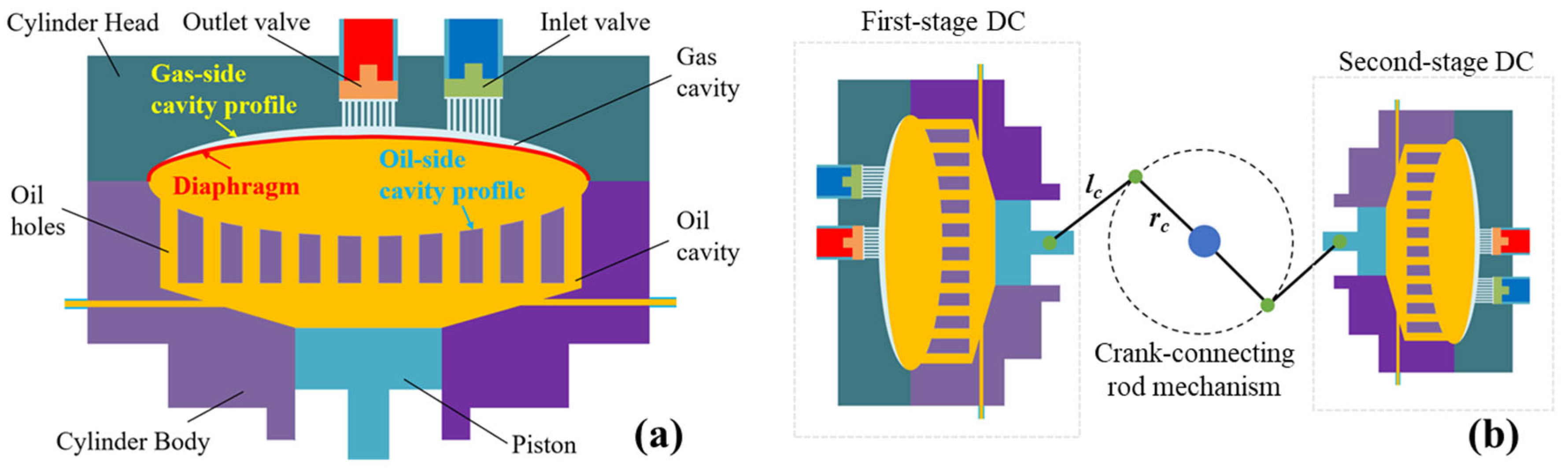
2. Descriptions of the DSDC

2.1. Working Principle

As shown in Figure 1a, the diaphragm compressor (DC) operates by driving hydraulic oil through piston movement, which induces diaphragm deformation to alter gas chamber volume and achieve gas compression within the chamber. The diaphragm physically separates the gas chamber from the oil chamber. Meanwhile, the gas-side and oil-side chambers of the diaphragm head assembly feature specialized cavity profiles to constrain diaphragm movement. As shown in Figure 1b, the dual-stage diaphragm compressor incorporates two distinct diaphragm heads driven by a crank-connecting rod mechanism, enabling sequential gas compression through first-stage and second-stage diaphragm compressors to attain the target pressure. Typically, the traditional single exponential diaphragm cavity profile (SEP) is mathematically described as
h a ( r ) = H Z a 1 2 r R Z a + 1 Z a + 1 r R 2 + Z a 1
where ha is the traditional diaphragm cavity profile function. Za is the deflection exponent. H is the cavity depth. R is the cavity radius. r is the radial distance from any point on the circular diaphragm to its central axis.
The complete operational cycle of the diaphragm compressor is described in Figure 2. During piston movement from the top dead center (TDC) to the bottom dead center (BDC), the oil filling pump supplies hydraulic oil to the oil chamber. When the gas chamber pressure drops below the preset suction pressure, the gas inlet valve opens, initiating the gas suction stage. As the piston moves from the BDC to the TDC, both gas and hydraulic oil pressures increase progressively, marking the compression stage. When the gas pressure exceeds the preset gas discharge pressure, the gas outlet valve opens, transitioning the diaphragm compressor into the gas discharge stage. When the hydraulic oil pressure surpasses the oil discharge threshold, the oil discharge valve opens, commencing the oil discharge stage.
Figure 3 shows the movement characteristics of the diaphragm during different stages. As shown in Figure 3a, when the piston reaches the BDC, the diaphragm also reaches its closest position to the oil chamber surface. Typically, a residual hydraulic oil clearance is intentionally maintained between the diaphragm and oil chamber surface at this position to prevent diaphragm rupture caused by stress concentration near oil holes under oil-starved conditions. As shown in Figure 3b, when the piston moves upward from the BDC toward the TDC, the diaphragm gradually approaches the gas chamber surface. Finally, as illustrated in Figure 3c, when the piston reaches the TDC, the diaphragm contacts the gas chamber surface.

2.2. Experimental Setup

The DSDC test rig is shown in Figure 4 and Figure 5. The system consisted of a first-stage diaphragm compressor (1s-DC), a second-stage diaphragm compressor (2s-DC), and a drive motor. Oil replenishment for both stages was facilitated by plunger pumps. The cylinder cooling was achieved through two integrated systems: cooling water circulation for the diaphragm heads of both stages, and hydraulic oil cooling via an oil circulation system serving both stages. Specifically, as illustrated in Figure 5b, after being cooled by the water chiller unit, the water flows through the water pipes to cool the diaphragm head. Following oil replenishment and overflow operations in the diaphragm compressor, the hydraulic oil is cooled via an oil cooler, thereby achieving the cooling effect for the diaphragm head. Moreover, gas suction, gas discharge, and oil discharge pressures were monitored via pressure pilot tubes connected to the pressure panels. The gas flowrate was measured via a gas flowmeter installed in the gas suction pipeline. Specifically, the diaphragm cavity profiles adopted by the first-stage and second-stage diaphragm compressors are detailed in Table 1. The detailed structural parameters of the DSDC are shown in Supplementary Material S1. The detailed parameters of the diaphragm material are shown in Supplementary Material S2. The specific test conditions for each operating scenario are shown in Supplementary Material S3. The models and measurement accuracies of the test instruments are listed in Supplementary Material S4.

3. Method

3.1. Volumetric Efficiency

The moving piston’s stroke volume with respect to the crank angle can be calculated by [24]
V h s ( α ) = π 4 D h s 2 r c [ ( 1 cos α ) + l c r c ( 1 1 r c 2 l c 2 sin 2 α ) ]
V s t = V h s ( π )
where Vhs is the piston’s moving stroke volume. α is the crank angle. Vst is the maximum stroke volume. Dhs is the piston diameter. rc is the crank radius. lc is the connecting rod length.
The volumetric efficiency of a diaphragm compressor is defined as the ratio of the actual suction volume to the theoretical suction volume, which can be expressed by the following formula [22]:
λ d = V s t Δ V l o s s V s t × 100 % = Q m g Q t h × 100 % = 1 V c V s t ( ε 1 k m 1 )
where λd is the volumetric efficiency. Δ Vloss is the suction volume loss, which is related to the suction heating, the volume expansion of the residual gas, pressure pulsation, and the compressibility of the hydraulic oil. Qmg is the experimental gas mass flowrate. Qth is the theoretical gas mass glow rate. Vc is the clearance volume. km is the expansion index. ε is the compression ratio.

3.2. Gas and Oil Pressure Model

During the operation of a diaphragm compressor, the pressures of hydraulic oil and gas undergo dynamic changes. The variation in gas pressure can be considered as a polytropic process, which can be described below [9].
(1)
Gas expansion stage
p g ( α ) V g k m ( α ) = p d g V c k m V g ( α ) = V c + V h s ( α ) + V o [ p g ( α ) p d g ] β ( 0 < α < α e x p )
where pg is the gas pressure. pdg is the gas outlet pressure. Vg is the gas cavity volume. Vo is the total hydraulic oil volume. β is the oil bulk modulus. αexp is the rotational angle when the gas inlet valve opens, which is solved by
p g ( α e x p ) = p s g
(2)
Gas suction stage
p g ( α ) = p s g ( α e x p < α < π )
(3)
Gas compression stage
p g ( α ) V g k n ( α ) = p s g ( V s t + V c ) k n V g ( α ) = V i n + V c V h s ( α ) V o [ p g ( α ) p s g ] β ( π < α < α c o m )
where kn is the compression index. Vin is the actual intake gas volume. psg is the gas inlet pressure. αcom is the rotational angle when the outlet valve opens, which is calculated by
p g ( α c o m ) = p d g ( π < α < α c o m )
(4)
Gas discharge stage
p g ( α ) = p d g ( α c o m < α < 2 π )
The hydraulic oil is treated as a compressible fluid. During the gas expansion, suction, and compression stages, the oil pressure is set equal to the gas pressure. The hydraulic oil pressure during other stages can be mathematically described below [9].
(1)
Oil expansion stage
Before the gas expansion process, the hydraulic oil under oil overflow pressure expands until it equals the residual gas’s pressure. This process can be described as
p o ( α ) = p d o β V o V h s ( α ) ( 0 < α < α o e x )
where po is the oil pressure in the cavity. αoex is the rotational angle when the oil’s expansion pressure equals the residual gas’s pressure.
(2)
Oil compression stage
p o ( α ) = p d g + β V o ( α o c o ) [ V h s ( 2 π ) V h s ( α ) ] ( α c o m < α o c o < α < α r e l )
where αoco is the rotational angle when the oil pressure surpasses the gas pressure, which can be estimated by
V h s ( α o c o ) = π D o p 2 L o p 4 ( 1 p d g p a t β ) ( π < θ < 2 π )
where Dop is the diameter of the oil pump’s plunger. Lop is the stroke of the oil pump’s plunger. pat is the atmospheric pressure. αrel is the rotational angle when the overflow valve opens, which could be estimated by
p o ( α r e l ) = p d o
where pdo is the oil overflow pressure.
(3)
Oil discharge stage
p o ( α ) = p d o ( α r e l < α < 2 π )
Finally, combined with experiments, the gas pressure and oil pressure variations within a complete operational cycle can be mathematically obtained.

3.3. Cavity Profile Design

The diaphragm cavity profile of the diaphragm compressor needs to meet the following requirements:
h ( 0 ) = 0 h ( R ) = H d h ( r ) d r r = 0 = d h ( r ) d r r = R = 0 d 2 h ( r ) d r 2 r = 0 0
where h is the deflection curve with respect to the radius r.
The double exponential diaphragm cavity profile (DEP) is described as [10,11]
h b ( r ) = H + H ( N b + 1 ) ( M b + 1 ) ( N b M b ) r R N b + 1 N b + 1 r R M b + 1 M b + 1
where hb is the DEP cavity profile function. Mb and Nb are the deflection exponents.
A novel double-arc diaphragm cavity profile (DAP) is proposed and described as
h N ( r ) = h N a ( r ) = H R N a + R N a 2 r 2 r [ 0 , λ N R ] h N b ( r ) = R N b R N b 2 ( r R ) 2 r [ λ N R , R ] ( 0 < λ N < 1 )
where hN is the DAP cavity profile function. hNa and hNb are the first and second arc segments, respectively. RNa and RNb are the first and second arc segments’ radii, respectively. λN is the dividing ratio of these two arc segments.
To meet the design requirements of Equation (16), the radii of the first and second arc segments (RNa and RNb) can be determined by the following equations:
λ N 2 ( 1 λ N ) 2 2 R N b 2 + 2 R N b 2 R 2 ( 1 λ N ) 2 + 2 λ N H + R N b 2 λ N 2 ( 1 λ N ) 2 R 2 λ N 2 1 λ N R N b + H + R N b 2 λ N 2 ( 1 λ N ) 2 R 2 λ N 2 2 + R 2 ( 1 λ N ) 2 = 0
R N a R N b = λ N 1 λ N
Consequently, in addition to the geometric parameters H (maximum deflection) and R (maximum radius), the SEP is characterized by a single adjustable design parameter (Za), the DEP has two adjustable design parameters (Nb and Mb), while the DAP has one adjustable design parameter (λN).

3.4. FEM Simulation Setup

Friction and sliding between diaphragms are not considered, and the deformation of diaphragms is assumed to be linear and isotropic. Then, the FEM simulation is developed using the ANSYS 2024 R1 software. Specifically, the domain partitioning is performed in the Design Modeler, and the grids are generated by the meshing module. As shown in Figure 6a, the geometric model used for FEM simulation comprises three diaphragm layers and a cylinder body. Due to the circumferential symmetry of the simplified geometric model, a quarter-section model is employed for reducing computational cost, with symmetric boundary conditions applied at the truncated surfaces. The three diaphragm layers are sequentially labeled as A, B, and C from top to bottom, with the upper surfaces designated as u-faces, the lower surfaces as d-faces, and the circumferential surfaces as c-faces. The cylinder body is labeled as D. To facilitate structured mesh generation, the diaphragms and cylinder body are divided into five meshing blocks, respectively. As shown in Figure 6b, the model is meshed using hexahedral elements, with three layers of mesh discretized in the thickness direction of the diaphragm. Then, the FEM computation and post-processing are conducted in the Mechanical module. The boundary conditions and loads of the FEM model are detailed in Table 2. Furthermore, the diaphragm deformations under varying differential pressures could be obtained through the FEM computation. The stress values extracted along the radial characteristic path of the diaphragm facilitate the calculation of circumferential and radial stresses on both the upper and lower surfaces.

3.5. Diaphragm Stress Model

Supplementary Material S5 indicates that the unidirectional relative elongation of the diaphragm in the radial direction is less than 0.1%. Therefore, assuming the diaphragm deformation in a diaphragm compressor is modeled as a static, circumferentially symmetric, isothermal, linear elastic circular plate, the stress analysis is shown in Figure 7, which can be described by the following equations [25]:
(1)
Force equilibrium equation in the radial direction (r)
Δ p d s r d s t sin θ [ δ Q b d s t + Δ ( δ Q b d s t ) ] sin θ + δ Q b d s t sin θ = δ P r b d s t cos θ [ δ P r b d s t + Δ ( δ P r b d s t ) ] cos ( θ + d θ ) + 2 δ P r b d s r sin ( d φ / 2 )
(2)
Force equilibrium equation in the axial direction (h)
Δ p d s r d s t cos θ δ Q b d s t + [ δ Q b d s t + d ( δ Q b d s t ) ] = δ P r b d s t sin θ [ δ P r b d s t + d ( δ P r b d s t ) ] sin ( θ + d θ )
(3)
Moment equilibrium equation for the circumferential section st
Δ p d s r d s t d s r / 2 [ δ Q d s t + d ( δ Q d s t ) ] d s r + [ δ P r d s t + d ( δ P r d s t ) ] = δ P r d s t + 2 δ P t d s r sin ( d φ / 2 )
where Δ p is the pressure difference. ds is the infinitesimal length element. δ is the stress. b is the diaphragm thickness. θ is the diaphragm deflection angle. φ is the circumferential angle. The subscripts r and t represent the radial and circumferential directions, respectively. The subscripts Pr, Pt, Mr, Mt, and Q represent radial tensile, circumferential tensile, radial bending, circumferential bending, and shear stresses, respectively. d represents the differential operator. For a microelement control volume (dsrdstb), the following simplifications can be made:
d s r = d r cos θ d r , d s t = r d φ sin θ θ ,     cos θ 1 , sin ( d φ / 2 ) d φ / 2
By further neglecting the higher-order infinitesimal terms, Equation (22) can be simplified to
Δ p r + ( δ Q b r ) + ( δ F r b r θ ) = 0
From Equation (25), the pressure difference can be described by
Δ p = ( δ Q b r ) + ( δ F r b r θ ) r
According to the thin-plate theory [26], different stresses can be calculated by the following equations [10,27]:
δ Q = b 3 E 12 ( 1 μ 2 ) d d r 1 r d d r r d h d r
δ M r = b E 2 1 μ 2 μ r d h d r + d 2 h d r 2
δ M t = b E 2 1 μ 2 1 r d h d r + μ d 2 h d r 2
δ P r = 1 μ 1 d 1 r r E d h d r 2 2 r d r d r r = R μ r E d h d r 2 2 r d r r 2 r = R + 1 r 2 r E d h d r 2 2 r d r
δ P t = 1 μ 1 d 1 r r E d h d r 2 2 r d r d r r = R μ r E d h d r 2 2 r d r r 2 r = R + d 1 r r E d h d r 2 2 r d r d r
where μ is Poisson’s ratio. E is the Young’s modulus of the diaphragm.
The surface stresses on the oil side and gas side of the three-layer diaphragm can be described as [10]
δ O r = δ P r + δ M r δ O t = δ P t + δ M t δ G r = δ P r δ M r δ G t = δ P t δ M t
where the subscripts O and G represent the oil-side and gas-side diaphragm surfaces, respectively.

3.6. Diaphragm Motion Model

The swept volume of the diaphragm at any specific crank angle compared to its undeformed shape can be described as
V m o = 2 π r h ( r , α ) d r
where Vmo is the swept volume of the diaphragm at any specific crank angle compared to its undeformed shape. h(r, α) is the diaphragm deflection as a function of both the crank angle α and the radius r.
Furthermore, the swept volume variation can be described by
Δ V m o = Δ V h s + Δ V o
where Δ Vmo is the swept volume variation in the diaphragm motion. Δ Vhs is the variation in the piston’s stroke volume during motion. Δ Vo is the volume change in the hydraulic oil, which can be described by
Δ V o = V o c ( 1 Δ p o / β )
where Voc is the total oil volume in the oil cavity. Δ po is the variation in the oil pressure. β is the oil bulk modulus.
Additionally, for diaphragm cavity surfaces with different profiles, diaphragm deformation under various pressure differences can be calculated using the finite element method (FEM). By fitting the discrete points of diaphragm deformation obtained from these calculations, the diaphragm swept volumes (Vmo) corresponding to different pressure differences can be determined. Then, in combination with Equation (32), the solution for diaphragm motion can be obtained.

3.7. Cavity Profile Optimization

The four principal surface stresses on the deformed diaphragm include δMt, δMr, δPt, and δPr. To evaluate the optimization potential of different diaphragm cavity profiles, the cavity diameter (R) and depth (H) were maintained constant while the maximum value among these four principal stresses was selected as the optimization objective. A comparative analysis was conducted to determine the optimal design parameters for various profile configurations. This methodology is mathematically formulated as follows [13]:
ψ ( ζ , R , H ) = M a x ( δ O r , δ O t , δ G r , δ G t ) h b e s t ( ζ , R , H ) = M i n ( ψ )
where Max and Min are the maximum and minimum functions, respectively. ψ is the optimization objective. ζ is the cavity profile design parameter. hbest is the optimized cavity profile function.

3.8. Complete Simulation Procedure

The complete simulation procedure is shown in Figure 8. Firstly, this paper carried out the performance testing experiments on a dual-stage diaphragm compressor, and the gas mass flowrate and volumetric efficiency under variable operating conditions were obtained. Then, by integrating the gas and oil pressure model, the fluid pressure variations at different crank angles can be quantified. Furthermore, the diaphragm deformation characteristics were investigated using the finite element method (FEM) and theoretical mechanics method, respectively. Specifically, the FEM simulation was validated through experimental results and the mesh independence analysis, while the theoretical mechanics model was validated by the FEM deformation and stress results. Moreover, using MATLAB R2022b’s ANN Fitting Toolbox [9,28], the relationship between the diaphragm central deflection and the diaphragm swept volume was fitted by incorporating the FEM deflection deformation results, which served as the simulation conditions for the diaphragm motion model. The detailed architecture of Matlab R2022b’s ANN-fitting model is described in Supplementary Material S6. Finally, diaphragm stresses associated with different diaphragm cavity profiles were analyzed, and the parameter optimization was further discussed. Through the experimental and simulation analyses conducted above, the diaphragm motion, stress distribution characteristics, and stress reduction strategy of the dual-stage diaphragm compressor were systematically investigated.

4. Results and Discussion

The simulation models will be validated in this chapter. Then, the experimental results, diaphragm stress distributions, movement characteristics, and cavity profile optimization of the DSDC will be systematically investigated and discussed.

4.1. Model Validation and Experimental Results

In this section, the FEM and theoretical stress analyses will be validated. Furthermore, the ANN fitting model based on the FEM simulation results will be constructed and discussed. Finally, based on the experimental results and pressure model, the fluid pressure variations under variable experimental conditions will be analyzed and discussed.

4.1.1. Mesh Independence Analysis

Figure 9 shows the mesh configurations with varying characteristic layer numbers. The MG-1, MG-2, and MG-3 grids progressively increased the radial mesh layers while maintaining a single element layer along the diaphragm thickness direction. The MG-4, MG-5, and MG-6 grids further increased the radial and thickness–direction layers. The MG-7 grid maintained five thickness–direction layers and increased both radial and central characteristic mesh layers. Figure 10 shows the FEM-calculated maximum radial stress results using these meshes. The results indicated that the MG-6 grid led to computational failure, which was attributed to its poor mesh quality. Additionally, FEM stress results from MG-1, MG-2, MG-3, MG-4, and MG-7 demonstrated that increasing radial mesh density progressively stabilized the computational results. Therefore, based on these observations, the MG-4 grid was selected for final FEM simulations due to its optimal balance between computational efficiency and solution stability.

4.1.2. Validation of the FEM and Theoretical Stress Models

Figure 11 shows the simulated and experimental diaphragm stress results for different types of diaphragm cavity profiles. As shown in Figure 11a, for the SEP-type cavity, a comparison between the diaphragm A and the diaphragm C in the FEM results show that the three-layer diaphragm assembly exhibited identical stress distribution characteristics within the cavity. The simulation results show consistent trends with experimental data from Reference [10], with a maximum stress deviation of 17.2% observed at the four radial measurement points. This result was consistent with the theoretical analysis results reported in the literature [10], which validated the correctness and accuracy of the simulation model. Moreover, the FEM results revealed that the surface stress distributions of different diaphragm layers (A and C) were consistent. Consequently, in the subsequent analysis, the stress distribution characteristics of the single diaphragm layer (A) were investigated and discussed. Furthermore, for the DAP-type cavity depicted in Figure 11b, the stress simulation results show abrupt changes at the junction point (λN = 0.85) due to the profile’s composition of two circular arcs. Moreover, both FEM and theoretical stress analysis exhibited congruent trends, with a calculated maximum surface stress deviation of 9.2%. Therefore, these findings confirmed that both FEM results and theoretical stress predictions effectively characterized the stress distributions of the deformed diaphragms in diaphragm compressors.

4.1.3. ANN-Fitting Model

Based on deformation simulation results obtained from the FEM simulations under various pressure differentials, the ANN fitting function was established with the central deflection (unit: mm) as the independent variable and diaphragm swept volume (unit: mm3) as the dependent variable, as illustrated in Figure 12. The Pearson correlation coefficient (R) and mean squared error (MSE) serve as critical metrics for evaluating ANN fitting accuracy [29]. For the first-stage and second-stage diaphragms, the ANN fitting functions achieved the Pearson correlation coefficients of 0.9992 and 0.9995, respectively, with corresponding MSE values of 1.25 × 10⁷ and 4.17 × 10⁵. These results demonstrated excellent agreement between the ANN fitting and FEM simulation results.

4.1.4. Experimental Results and Pressure Variations

Figure 13 shows the variation trends of gas mass flowrate and volumetric efficiency for a DSDC under different experimental conditions. As shown in Figure 13a, the experimental results indicated that the gas mass flowrate (Qmg) of the DSDC increased with elevated rotational speed (n), while it decreased with higher second-stage discharge pressure (pdg2). The maximum gas flowrate of 508.0 kg/h was achieved under the case #3 experimental condition. Figure 13b shows the volumetric efficiency variations for both first-stage and second-stage diaphragm compressors across different experimental conditions. The results revealed that the volumetric efficiency of both stages decreased with increasing rotational speed and second-stage discharge pressure. The highest volumetric efficiencies were observed under the case #1 condition, reaching 74.02% for the first stage DC and 87.63% for the second stage DC. Furthermore, based on the volumetric efficiency results, experimental oil overflow pressure results, gas pressure results, and the pressure variation model, the variations in oil and gas pressures of the DSDC could be derived, as detailed in Figure 14. It was observed that the crank angle for the gas expansion stage increased with decreasing volumetric efficiency. Specifically, a comparison between case #1 and case #3 operating conditions revealed that the crank angle during the gas expansion stage increased by approximately 10° for both the first-stage and second-stage diaphragm compressors.

4.2. Diaphragm Movement and Stress Characteristics of the DSDC

This section will investigate the diaphragm motion and stress distribution characteristics under different experimental conditions of the DSDC.

4.2.1. Diaphragm Deformation Under Different Pressure Conditions

Figure 15 shows the FEM simulation results of the diaphragm deformation under varying pressure conditions. As the pressure acting on the diaphragm surface increased, the diaphragm deformation became progressively more pronounced, with deflection magnitudes increasing until the diaphragm fully conformed to the cavity geometry. As shown in Figure 15a, the first-stage diaphragm exhibited smoother volume (Vmo) variation with increasing pressure difference ( Δ p) compared to the second-stage diaphragm, requiring a higher pressure difference ( Δ p) to achieve maximum chamber volume (Vmo). Figure 15b,c shows that the radial diaphragm deflection followed similar trends with pressure difference for both stage diaphragm compressors. Moreover, the results indicated that the diaphragm center required significantly greater pressure difference to contact the cavity geometry compared to the edge regions, which revealed that insufficient oil-gas pressure difference could lead to residual clearance volume at the diaphragm center, thereby reducing the volumetric efficiency. Specifically, the first-stage diaphragm required a pressure difference of 85.58 kPa to fully conform to the cavity surface, while the second-stage diaphragm necessitated 75.49 kPa to achieve a similar contact.

4.2.2. Diaphragm Movement Under Different Experimental Conditions

Figure 16 shows the radial deformation behavior of diaphragms under varying experimental conditions across different crank angles. As depicted in Figure 16a,b, the center deflection exhibited similar trends under different operating conditions, while minor differences emerged at the BDC position, attributed to the coupled effects of volumetric efficiency variations and hydraulic oil compressibility. Specifically, case #1 operating condition achieved maximum center deflection at the BDC position, with the first-stage diaphragm reaching 4.14 mm and the second-stage diaphragm reaching 2.53 mm. Figure 16c,d shows the radial diaphragm stress variations under the specific case #3 condition across different crank angles. The results indicated that during piston movement from the TDC position to the BDC position, the diaphragm center region (ρr = 0) detached from the gas-side cavity surface earlier than the edge regions (ρr = 0.8). Moreover, both first-stage and second-stage diaphragms reached zero center deflection at approximately 105° crank angle, while the second-stage diaphragm exhibited a steeper deflection gradient near the zero-deflection point.

4.2.3. Diaphragm Stress Distribution Under the Specific Case #3 Condition

Figure 17 shows the simulation results of surface stress under the condition of case #3. Figure 17a,b shows the stress distributions of the first-stage and second-stage diaphragms at the TDC position, respectively. The results revealed that the first-stage gas-side diaphragm surface exhibited a maximum radial stress of 176.48 MPa at the edge region, while the oil-side surface showed a peak circumferential stress of 180.16 MPa at the center. For the second-stage diaphragm, maximum radial stress of 185.56 MPa occurred at the diaphragm center, while the oil-side surface showed peak radial stress of 139.44 MPa at the edge region. Moreover, it was observed that the gas-side center regions exhibited higher stress magnitudes at the TDC position, whereas the oil-side edge regions exhibited higher stress magnitudes. Combined with the diaphragm movement behavior under the case #3 condition, the derived stress distributions at the BDC position are illustrated in Figure 17c,d. The first-stage oil-side diaphragm center reached a maximum stress of 47.19 MPa, while the second-stage oil-side center recorded 40.90 MPa at the BDC position. Furthermore, these results indicated that the surface stress of the diaphragm at the TDC position was significantly higher than that at the BDC position. This strategy was designed and developed to prevent diaphragm rupture caused by adhesion to the oil-side chamber surface under oil-deficient operating conditions. Moreover, the variation in maximum surface stress with the Young’s modulus is shown in Supplementary Material S7.

4.3. Further Discussion on the Cavity Profile Optimization

This section will further investigate the impact of design parameters for three diaphragm cavity profiles (SEP, DEP, and DAP) on the surface stress distribution and discuss the comparative optimization results.

4.3.1. SEP-Type Cavity Profile

Figure 18 shows the impact of the exponent Za on the diaphragm stress (δ) and swept volume (Vmo). As shown in Figure 18a,c, with constant cavity depth and radius parameters for both first-stage and second-stage diaphragm compressor heads, increasing the exponent Za initially reduced diaphragm stress before inducing a subsequent stress increase, while simultaneously causing a gradual increase in diaphragm swept volume. Figure 18b,d shows the optimized stress distributions for first-stage and second-stage diaphragm compressors under minimum stress design conditions. The results indicated that within the Za range of [2,10], the first-stage diaphragm achieved a minimum surface stress of 179.96 MPa with a corresponding swept volume of 0.001116 m3, while the second-stage compressor diaphragm reached a minimum stress of 175.72 MPa with a swept volume of 0.000362 m3. The optimized cavity profiles demonstrated comparable maximum principal stresses at both center and edge regions.

4.3.2. DEP-Type Cavity Profile

Figure 19a,b shows the influence of design parameters (Mb and Nb) on the DEP-type cavity profile under the first-stage geometric design parameters (R = 0.315 m, H = 0.009 m), while Figure 19c,d shows corresponding parameter effects under the second-stage geometric design parameters (R = 0.223 m, H = 0.0061 m). The results identified an optimal reference design range (Mb [1, 1.9] and Nb [1,15]) where minimum stress optimization was achievable. Meanwhile, the diaphragm swept cavity volume (Vmo) exhibited a progressive increase with elevated Mb and Nb values. Figure 19e,f shows the stress distributions for the first-stage and second-stage DEP-type cavities under minimum stress design conditions. Specifically, the first-stage optimized DEP-type cavity profile achieved a maximum principal stress of 179.96 MPa at the Mb of 1.1 and the Nb of 6.2617, while the second-stage optimized DEP-type cavity profile reached 175.15 MPa at the Mb of 1.1 and the Nb of 4.8523.

4.3.3. DAP-Type Cavity Profile

Figure 20 shows the influence of DAP-type profile design parameter (λN) on the diaphragm stress (δ) and diaphragm swept volume (Vmo). Within the design interval [0.25, 0.85], increasing parameter λN initially reduced the diaphragm stress before inducing a subsequent stress increase, while simultaneously causing a gradual increase in the diaphragm swept volume. Specifically, Figure 20a,b shows the stress distribution and swept volume variations for the first-stage geometric parameters (R and H), while Figure 20c,d shows the corresponding second-stage configuration results. The results revealed that at the λN of 0.79, both first-stage and second-stage DAP-type cavity profiles achieved a minimum value of δmax. The first-stage diaphragm within the optimized DAP-type cavity exhibited 173.95 MPa maximum principal stress with 0.001129 m3 swept volume, whereas the second-stage configuration reached 172.57 MPa stress with 0.0003835 m3 swept volume.

4.3.4. Optimization Comparison

Figure 21 shows the diaphragm characteristics with optimized cavity profiles. In detail, Figure 21a,c illustrates the optimized cavity profiles for the first-stage and second-stage diaphragm compressors, respectively. It was observable that the optimized DAP-type cavity profile exhibited greater deflection near the radial location of ρr = 0.6, resulting in increased cavity volume. Moreover, with the characteristic parameter λN = 0.79, an inflection point in cavity profile slope was observed at ρr = 0.79. Figure 21b,d compares the performance ratios (K) in terms of pressure difference ( Δ p), maximum principal stress (δmax), and diaphragm swept volume (Vmo). The results indicated that the DAP-type cavity profile demonstrated enhanced volume and reduced stress levels but required higher operating pressure differences. Specifically, the optimized first-stage SEP, DEP, and DAP profiles exhibited pressure differences 1.013, 1.022, and 1.151 times the baseline values of the experimental SEP-type profiles (shown in Figure 15), respectively, while the second-stage counterparts required 1.173-, 1.197-, and 1.456-times pressure differences. Moreover, the optimized first-stage and second-stage DAP-type diaphragm swept volumes achieved 1.017 times and 1.171 times the baseline values of the experimental SEP-type profiles, respectively.

5. Conclusions

This paper investigated the stress distribution, movement characteristics, and stress optimization potential of diaphragms in a dual-stage diaphragm compressor. Firstly, a finite element method (FEM) model and a theoretical stress analysis model were developed and validated through experimental comparisons. Subsequently, by integrating experimental pressure and gas mass flowrate data with the fluid pressure model, the variations in oil and gas pressures within the dual-stage diaphragm compressor were calculated. Furthermore, building upon these foundations, the diaphragm movement characteristics and stress distributions were systematically analyzed through the diaphragm motion and stress models. Finally, a novel double arc cavity profile was proposed, and the optimization comparison was conducted on various diaphragm cavity profile configurations. Key findings were summarized as follows:
(1)
The DSDC experimental results indicated that under operating conditions of 1.6 MPa suction pressure, 8 MPa second-stage discharge pressure, and 200 rpm rotational speed, the volumetric efficiencies reached 74.02% and 87.63% for the first-stage and second-stage diaphragm compressors, respectively.
(2)
The theoretical stress analysis results indicated that for the DSDC test rig, the driving pressure differences at the TDC position reached 85.58 kPa for the first-stage diaphragm and 75.49 kPa for the second-stage diaphragm.
(3)
The diaphragm movement analysis results indicated that under operating conditions of 1.6 MPa suction pressure, 8 MPa second-stage discharge pressure, and 200 rpm rotational speed, the first-stage and second-stage diaphragms reached the maximum center deflections of 4.14 mm and 2.53 mm, respectively, at the BDC position.
(4)
The optimized first-stage SEP, DEP, and DAP diaphragm cavity profiles reached cavity volumes of 1.005, 1.015, and 1.017 times that of the experimental SEP profile, respectively, while the maximum principal stresses were reduced to 0.999, 0.993, and 0.965 times the baseline value. The optimized second-stage SEP, DEP, and DAP diaphragm cavity profiles reached cavity volumes of 1.104, 1.111, and 1.171 times the experimental SEP baseline, accompanied by maximum principal stress reductions to 0.947, 0.944, and 0.930 times the baseline value.
The diaphragm movement analysis and stress optimization results investigated in this paper will provide valuable references for the diaphragm compressor’s design optimization. However, factors including the fatigue life of diaphragms in novel diaphragm cavity profiles, the nonlinear deformation, and the friction or sliding effects between diaphragms were not considered in the model. In future work, the influence of oil holes and gas valve ports on diaphragm stress distributions within optimized diaphragm cavities will be experimentally investigated. Moreover, the high-cycle fatigue life of diaphragms in novel diaphragm cavity structures and the experimental performance of dual-stage diaphragm compressors will be further investigated.

Supplementary Materials

The following supporting information can be downloaded at https://www.mdpi.com/article/10.3390/app15158353/s1, Figure S1: Radial relative elongation; Figure S2: ANN-fitting architecture of the Matlab; Figure S3: Variation of maximum surface stress with the Young’s modulus; Table S1: Detailed parameters of DSDC system; Table S2: Diaphragm material; Table S3: Preset experimental conditions; Table S4: Measurements and instrument accuracies.

Author Contributions

Conceptualization, C.S.; Methodology, C.S.; Software, C.S., X.C., J.T., M.Y. and X.K.; Validation, C.S.; Formal analysis, C.S.; Investigation, C.S.; Data curation, C.S. and X.C.; Writing—original draft, C.S.; Writing—review & editing, C.S. and Z.H.; Visualization, D.L.; Supervision, Z.H. and D.L.; Project administration, Z.H.; Funding acquisition, Z.H. All authors have read and agreed to the published version of the manuscript.

Funding

This research received no external funding.

Institutional Review Board Statement

Not applicable.

Informed Consent Statement

Not applicable.

Data Availability Statement

Data is contained within the article or Supplementary Material.

Conflicts of Interest

The authors declare no conflict of interest.

Nomenclature

Abbreviations
BDCBottom Dead Center
DAPDouble-Arc Profile
DCDiaphragm Compressor
DEPDouble Exponential Profile
DSDCDual-Stage Diaphragm Compressor
FEMFinite Element Method
FSIFluid–Structure Interaction
SEPSingle Exponential Profile
TDCTop Dead Center
Symbols
bDiaphragm thickness (m)
DDiameter (m)
EElastic modulus (Pa)
hCavity deflection curve (m)
HMaximum diaphragm deflection (m)
km, knExpansion and compression indexes (-)
lcConnecting rod length (m)
LLength (m)
Mb, NbDesign parameters of the DEP profile (-)
nRotational speed (rpm)
NMGMesh grid number (-)
pGas pressure (Pa)
QmgExperimental gas mass flowrate (kg·h−1)
QthTheoretical gas mass flowrate (kg·h−1)
rRadius (m)
rcCrank radius (m)
RDiaphragm cavity radius (m)
RNa, RNbSegment radii of the DAP profile (m)
sCharacteristic diaphragm length (m)
VVolume (m3)
VcResidual volume (m3)
VinInlet gas volume (m3)
VlossSuction volume loss (m3)
VmoDiaphragm swept volume (m3)
VocTotal oil cavity volume (m3)
ZaDesign parameter of the SEP profile (-)
αCrank angle (rad)
βOil bulk modulus (Pa)
Δ pDiaphragm pressure difference (Pa)
δDiaphragm stress (MPa)
θDeflection angle (rad)
λdVolumetric efficiency (-)
λNDesign parameter of the DAP profile (-)
μPoisson’s ratio (-)
ρrSpecific radius (-)
φRadial angle (rad)
Subscripts
1s, 2sFirst-stage and second-stage
a, b, NSEP, DEP, DAP profiles
atAtmosphere
A, B, CThree-layer diaphragms
Exp, OptExperimental and optimized results
g, oGas and oil
hsMoving piston
opOil pump
P, M, QTensile, bending, and shear stresses
r, tRadial and circumferential directions
stStroke
s, dSuction and discharge
u, d, cUpper, lower, and circumferential surfaces
zCrank-connecting rod mechanism

References

  1. Khademi, M.M.; Kasaeian, A. Hydrogen production using solar heliostat fields: A review. Energy 2025, 314, 134259. [Google Scholar] [CrossRef]
  2. Woon, K.S.; Phuang, Z.X.; Taler, J.; Varbanov, P.S.; Chong, C.T.; Klemes, J.J.; Lee, C.T. Recent advances in urban green energy development towards carbon emissions neutrality. Energy 2023, 267, 126502. [Google Scholar] [CrossRef]
  3. Huang, J.Z.; Lu, D.N.; Huang, X.A.; Hu, Z.D.; Liu, L.; Lin, C.Z.; Jing, R.; Xie, C.P.; Brandon, N.; Zheng, X.Y. Is China ready for a hydrogen economy? Feasibility analysis of hydrogen energy in the Chinese transportation sector. Renew Energ. 2024, 223, 119964. [Google Scholar] [CrossRef]
  4. Otsubo, Y. Hydrogen compression and long-distance transportation: Emerging technologies and applications in the oil and gas industry-A technical review. Energ. Convers. Manag. X 2025, 25, 100836. [Google Scholar] [CrossRef]
  5. Rasul, M.G.; Hazrat, M.A.; Sattar, M.A.; Jahirul, M.I.; Shearer, M.J. The future of hydrogen: Challenges on production, storage and applications. Energ Convers. Manag. 2022, 272, 11632. [Google Scholar] [CrossRef]
  6. Guo, Y.; Wang, Q.; Cao, J.H.; Wang, Y.L.; Peng, X.Y. Performance assessment and optimisation of a concentric two-piston compressor system for hydrogen storage. Energ. Convers. Manag. 2024, 310, 118470. [Google Scholar] [CrossRef]
  7. Tahan, M.R. Recent advances in hydrogen compressors for use in large-scale renewable energy integration. Int. J. Hydrog. Energy 2022, 47, 35275–35292. [Google Scholar] [CrossRef]
  8. Giuffrida, A.; Colbertaldo, P. Overview of diaphragm compressors for hydrogen service: Capacity, discharge pressure and operational challenges. J. Energy Storage 2025, 129, 117286. [Google Scholar] [CrossRef]
  9. Sun, C.Z.; He, Z.L.; Chen, X.Q.; Li, D.T.; Ma, K.; Chen, M.Y.; Wang, T.; Wang, X.L. Thermodynamic, sensitivity analyses and optimization of a dual-stage diaphragm compressor system: A model-based and experimental study. Energy 2025, 330, 136848. [Google Scholar] [CrossRef]
  10. Li, J.Y.; Jia, X.H.; Wu, Z.M.; Peng, X.Y. The cavity profile of a diaphragm compressor for a hydrogen refueling station. Int. J. Hydrog. Energy 2014, 39, 3926–3935. [Google Scholar] [CrossRef]
  11. Li, J.Y.; Liang, L.; Jia, X.H.; Peng, X.Y. A new generatrix of the cavity profile of a diaphragm compressor. Proc. Inst. Mech. Eng. Part C J. Mech. Eng. Sci. 2014, 228, 1754–1766. [Google Scholar] [CrossRef]
  12. Jia, X.H.; Zhao, Y.; Chen, J.H.; Peng, X.Y. Research on the flowrate and diaphragm movement in a diaphragm compressor for a hydrogen refueling station. Int. J. Hydrog. Energy 2016, 41, 14842–14851. [Google Scholar] [CrossRef]
  13. Hu, Y.L.; Xu, X.Y.; Wang, W. A new cavity profile for a diaphragm compressor used in hydrogen fueling stations. Int. J. Hydrog. Energy 2017, 42, 24458–24469. [Google Scholar] [CrossRef]
  14. Wang, T.; Tang, Z.; Jia, X.H. Study on the stress and deformation of a diaphragm compressor cylinder head under extreme conditions. Int. Conf. Compress. Their Syst. 2019, 604, 012029. [Google Scholar] [CrossRef]
  15. Wang, T.; Jia, X.H.; Li, X.Y.; Ren, S.D.; Peng, X.Y. Thermal-structural coupled analysis and improvement of the diaphragm compressor cylinder head for a hydrogen refueling station. Int. J. Hydrog. Energy 2020, 45, 809–821. [Google Scholar] [CrossRef]
  16. Wang, Q.S.; He, G.L.; Zhao, W.J.; Han, Z.H.; Wei, L.L. Design of GH4169 diaphragm for combined improvements of yield strength and surface roughness. Clean Energy 2023, 7, 53–58. [Google Scholar] [CrossRef]
  17. Lei, J.G.; Lin, Z.J.; Zhu, Q.; Han, G.Y.; Li, P. Analysis of diaphragm compressor exhausts volume decrease. Int. Conf. Meas. 2013, 233–235. [Google Scholar] [CrossRef]
  18. Ren, S.D.; Jia, X.H.; Jiang, J.C.; Zhang, S.T.; Zhao, B.; Peng, X.Y. Effect of hydraulic oil compressibility on the volumetric efficiency of a diaphragm compressor for hydrogen refueling stations. Int. J. Hydrog. Energy 2022, 47, 15224–15235. [Google Scholar] [CrossRef]
  19. Ren, S.D.; Jia, X.H.; Shi, L.; Li, K.; Peng, X.Y. Theoretical and experimental study on improving diaphragm compressor design for hydrogen refueling stations through use of a free moving oil piston concept. J. Energy Storage 2023, 74, 109397. [Google Scholar] [CrossRef]
  20. Ren, S.D.; Jia, X.H.; Li, K.; Chen, F.; Zhang, S.T.; Shi, P.; Peng, X. Enhancement performance of a diaphragm compressor in hydrogen refueling stations by managing hydraulic oil temperature. Case Stud. Therm. Eng. 2024, 53, 103905. [Google Scholar] [CrossRef]
  21. Zhao, Y.L.; Guo, Y.; Diao, A.N.; Zhang, J.T.; Peng, X.Y. Thermodynamic analysis of diaphragm compressor in hydrogen refuelling stations by using fluid-structure interaction method. Appl. Therm. Eng. 2024, 242, 122394. [Google Scholar] [CrossRef]
  22. Zhao, Y.L.; Zhao, B.; Yao, Y.C.; Jia, X.H.; Peng, X.Y. Experimental study and sensitivity analysis of performance for a hydrogen diaphragm compressor. Renew Energ. 2024, 237, 121871. [Google Scholar] [CrossRef]
  23. Zhao, Z.R.; Wang, G.F.; Zhang, J.Y.; Tian, Y.F. Study on the characteristics of a novel wrap-around cooled diaphragm compressor for hydrogen refueling station. Case Stud. Therm. Eng. 2024, 56, 104242. [Google Scholar] [CrossRef]
  24. Qu, Z.C. Reciprocating Compressor Principle, 2nd ed.; Xi’an Jiaotong University Press: Xi’an, China, 2018. [Google Scholar]
  25. Reddy, J.N. Theory and Analysis of Elastic Plates and Shells, 2nd ed.; CRC Press: Boca Raton, FL, USA, 2006. [Google Scholar]
  26. Mittelstedt, C. Theory of Plates and Shells; Springer Vieweg: Berlin, Germany, 2023. [Google Scholar]
  27. Sapsathiarn, Y.; Rajapakse, R.K.N.D. Finite-element modeling of circular nanoplates. J. Nanomech. Micromech. 2013, 3, 59–66. [Google Scholar] [CrossRef]
  28. Mcculloch, W.S.; Pitts, W. A logical calculus of the ideas immanent in nervous activity. Bull. Math. Biol. 1990, 52, 99–115. [Google Scholar] [CrossRef]
  29. Xu, G.P.; Yu, Z.T.; Xia, L.; Wang, C.J.; Ji, S.B. Performance improvement of solid oxide fuel cells by combining three-dimensional CFD modeling, artificial neural network and genetic algorithm. Energ. Convers. Manage. 2022, 268, 116026. [Google Scholar] [CrossRef]
Figure 1. Geometric structures of the diaphragm compressor. (a) Diaphragm head. (b) DSDC.
Applsci 15 08353 g001
Figure 2. Working stages of the diaphragm compressor.
Applsci 15 08353 g002
Figure 3. Schematic diagram of the diaphragm motion within the chamber. (a) Diaphragm position when the piston reaches the bottom dead center (BDC). (b) Diaphragm position at any intermediate position during piston motion. (c) Diaphragm position when the piston reaches the top dead center (TDC).
Applsci 15 08353 g003
Figure 4. Experimental prototype.
Applsci 15 08353 g004
Figure 5. Diaphragm cylinder of the DSDC. (a) Prototype. (b) Cross-sectional view of the cylinder head.
Applsci 15 08353 g005
Figure 6. FEM simulation setup. (a) Quarter geometric structure and meshing blocks. (b) Mesh grids of the diaphragm and cylinder body.
Applsci 15 08353 g006
Figure 7. Theoretical mechanics analysis of the diaphragm.
Applsci 15 08353 g007
Figure 8. Simulation flowchart.
Applsci 15 08353 g008
Figure 9. Different numbers of mesh elements for the FEM simulation.
Applsci 15 08353 g009
Figure 10. FEM results of the mesh independence analysis.
Applsci 15 08353 g010
Figure 11. Validation of the stress simulation results. (a) Comparison of the simulated and experimental results for a SEP-type profile cavity. (b) Comparison of the FEM and theoretical stress simulation results for a DAP-type profile cavity.
Applsci 15 08353 g011
Figure 12. ANN fitting process and validation. (a) Comparative analysis of ANN fitting and FEM simulation results for the first-stage swept volume (Vmo). (b) ANN iterative process for the first-stage swept volume. (c) Comparative analysis of ANN fitting and FEM simulation results for the second-stage swept volume. (d) ANN iterative process for the second-stage swept volume.
Applsci 15 08353 g012
Figure 13. Experimental performance of the DSDC under various conditions. (a) Gas mass flowrate. (b) Volumetric efficiency.
Applsci 15 08353 g013
Figure 14. Variations in oil and gas pressures with the crank angle under different experimental conditions. (a) Case #1. (b) Case #2. (c) Case #3. (d) Case #4. (e) Case #5.
Applsci 15 08353 g014
Figure 15. Diaphragm deformation under different pressure conditions. (a) Swept volume variation in the deformed diaphragm (Vmo). (b) Radial deflection variation in the first-stage diaphragm. (c) Radial deflection variation in the second-stage diaphragm.
Applsci 15 08353 g015
Figure 16. Diaphragm deflection variation with the crank angle under different experimental conditions. (a) First-stage diaphragm center deflection. (b) Second-stage diaphragm center deflection. (c) Radial deflection of the first-stage diaphragm under the case #3 condition. (d) Radial deflection of the second-stage diaphragm under case #3 condition.
Applsci 15 08353 g016
Figure 17. Theoretical simulation results of diaphragm stress at the TDC and BDC positions under the case #3 condition. (a) 1s-DC: TDC position. (b) 2s-DC: TDC position. (c) 1s-DC: BDC position. (d) 2s-DC: BDC position.
Applsci 15 08353 g017
Figure 18. Diaphragm stress optimization for SEP-type cavity profiles. (a) Impact of profile parameter (Za) on the first-stage maximum diaphragm stress (δmax) and swept volume (Vmo). (b) First-stage diaphragm stress and swept volume variations within the profile parameter ranges. (c) Impact of profile parameter on the second-stage maximum diaphragm stress and swept volume. (d) Second-stage diaphragm stress and swept volume variations within the profile parameter ranges.
Applsci 15 08353 g018
Figure 19. Diaphragm stress optimization for DEP-type cavity profiles. (a) Impact of profile parameters (Mb and Nb) on the first-stage maximum diaphragm stress (δmax). (b) Impact of profile parameters on the first-stage swept volume (Vmo). (c) Impact of profile parameters on the second-stage maximum diaphragm stress. (d) Impact of profile parameters on the second-stage swept volume. (e) Stress distributions of the first-stage diaphragm within the optimized DEP-type cavity. (f) Stress distributions of the second-stage diaphragm within the optimized DEP-type cavity.
Applsci 15 08353 g019
Figure 20. Diaphragm stress optimization for DAP-type cavity profiles. (a) Impact of profile parameter (λN) on the first-stage maximum diaphragm stress (δmax) and swept volume (Vmo). (b) First-stage diaphragm stress and swept volume variations within the profile parameter ranges. (c) Impact of profile parameter on the second-stage maximum diaphragm stress and swept volume. (d) Second-stage diaphragm stress and swept volume variations within the profile parameter ranges.
Applsci 15 08353 g020
Figure 21. Optimization results. (a) First-stage cavity profiles. (b) First-stage diaphragm’s characteristics. (c) Second-stage cavity profiles. (d) Second-stage diaphragm’s characteristics.
Applsci 15 08353 g021
Table 1. Diaphragm cavity profiles of the DSDC.
ProfileDepth
H (mm)
Radius
R (mm)
Exponential
Za (-)
Piston Diameter
Dz (mm)
Stroke Length
Lz (mm)
1s-DCSEP93156.6110180
2s-DC6.12233.460180
Table 2. The boundary conditions and loads of the FEM model.
Surfaces and Blocks (“::” Means Contact Faces)Contact Type/Load
(1) Meshing blocks of each component
1::2::3::4::5
Bonded
(2) Edge blocks of diaphragms
Ad4::Bu4, Bd4::Cu4, Cd4::Du4,
Ad5::Bu5, Bd5::Cu5, Cd5::Du5
Bonded
(3) Center blocks of diaphragms
Ad1::Bu1, Ad2::Bu2, Ad3::Bu3,
Bd1::Cu1, Bd2::Cu2, Bd3::Cu3
No separation
(4) Surfaces between diaphragms and cylinder body
Cd1::Du1, Cd2::Du2, Cd3::Du3
Frictional
(5) Load surface: Au1, Au2, Au3Pressure difference ( Δ p)
(6) Fixed surface: Dd1, Dd2, Dd3, Dd4, Dd5Fixed
Disclaimer/Publisher’s Note: The statements, opinions and data contained in all publications are solely those of the individual author(s) and contributor(s) and not of MDPI and/or the editor(s). MDPI and/or the editor(s) disclaim responsibility for any injury to people or property resulting from any ideas, methods, instructions or products referred to in the content.

