
Systematic Analysis of the Hydrogen Value Chain from Production to Utilization

 , , ,
, , ,  and
and
Abstract
1. Introduction
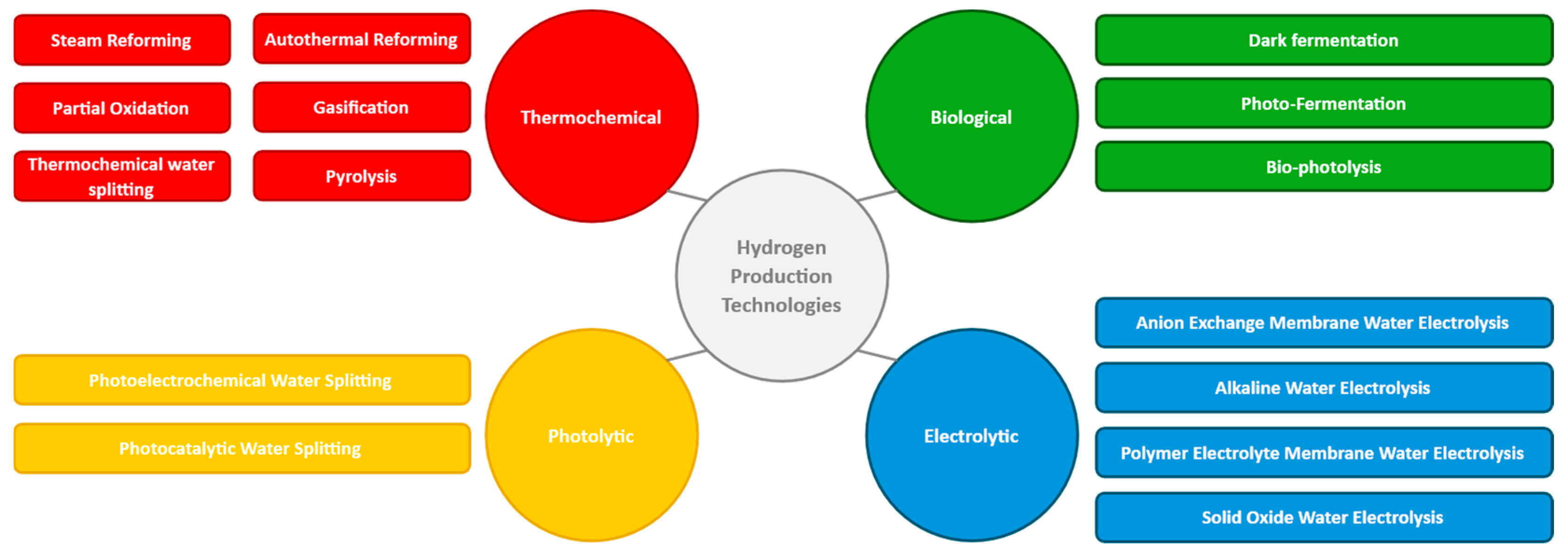
2. Hydrogen Production Technologies
2.1. Thermochemical Processes
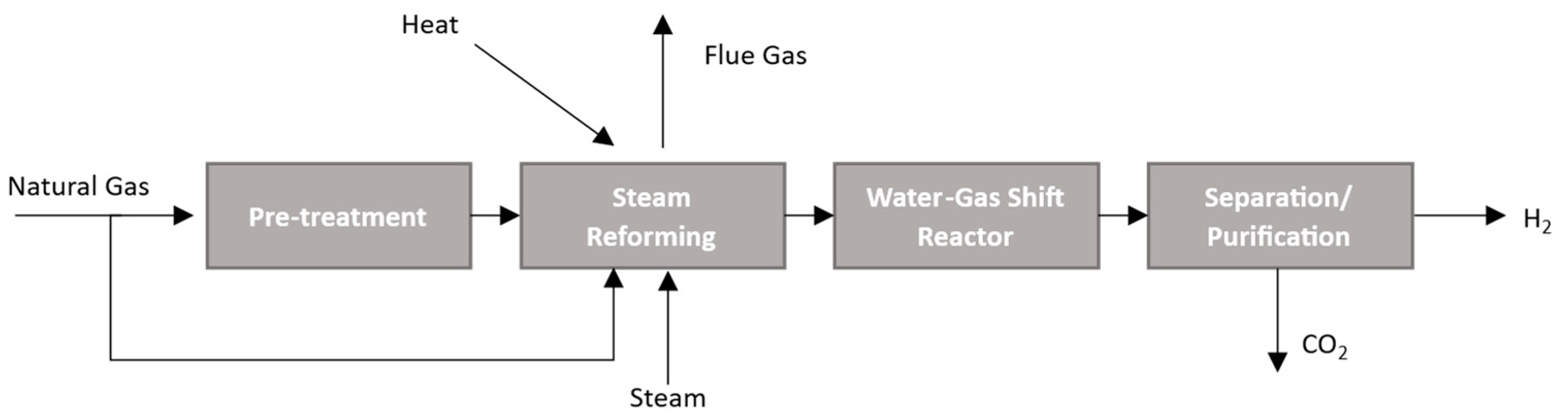
2.1.1. Steam Reforming
2.1.2. Partial Oxidation
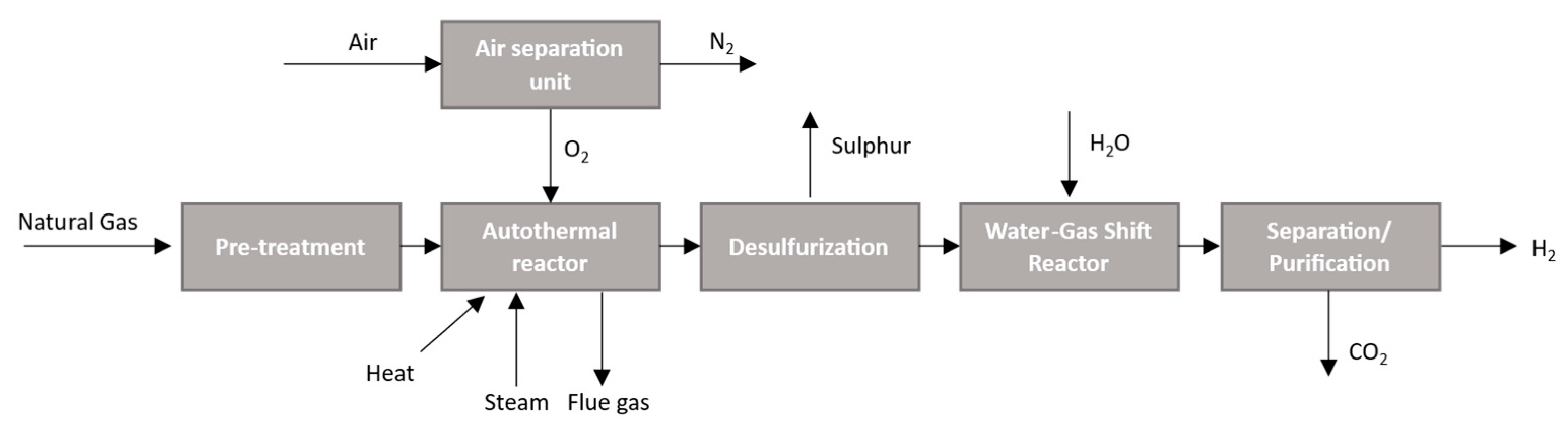
2.1.3. Autothermal Reforming
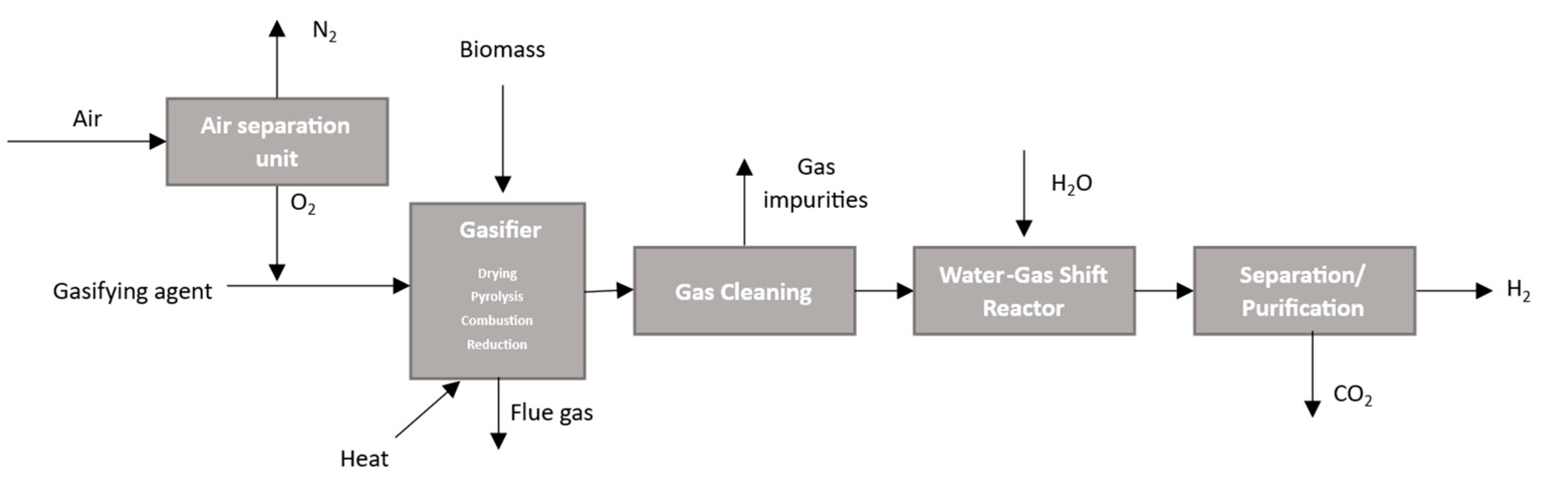
2.1.4. Gasification
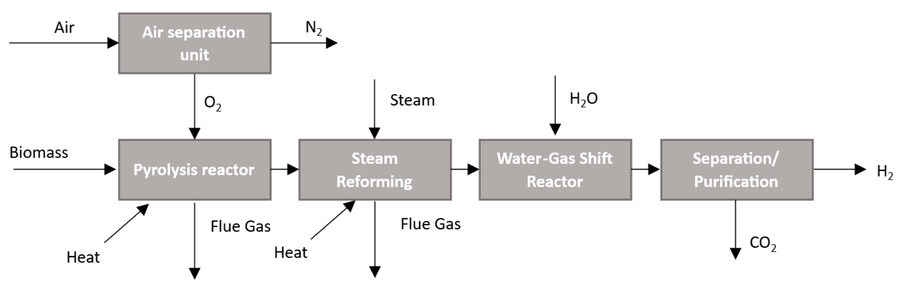
2.1.5. Pyrolysis
2.1.6. Thermochemical Water Splitting
2.2. Biological Processes
2.3. Electrolysis
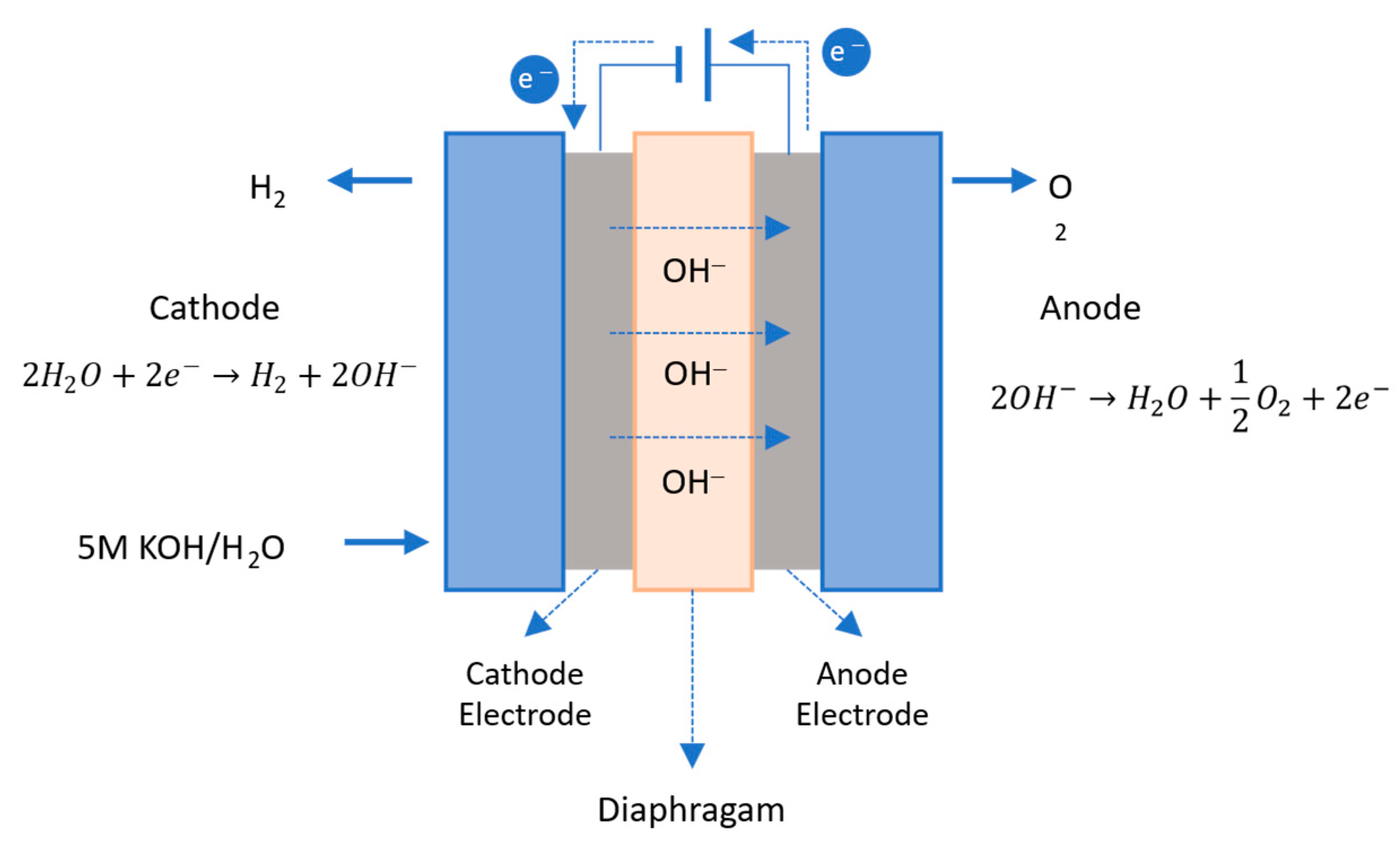
2.3.1. Alkaline Water Electrolysis
2.3.2. Polymer Electrolyte Membrane Water Electrolysis
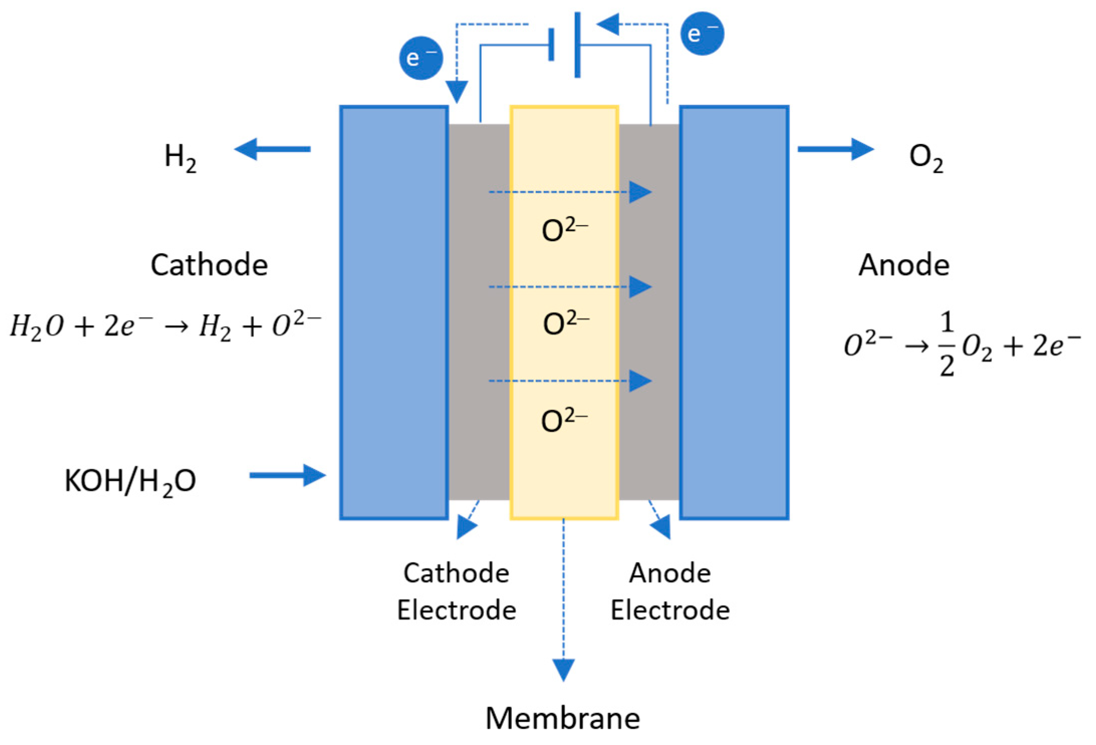
2.3.3. Solid Oxide Water Electrolysis
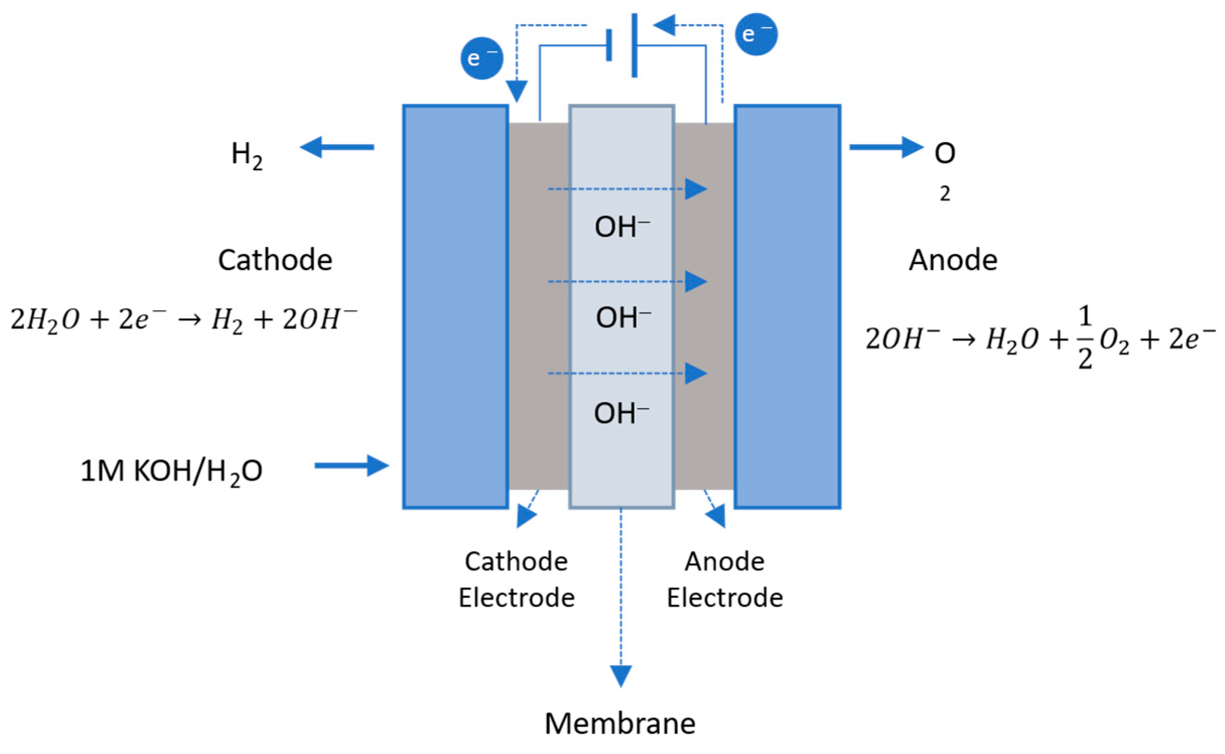
2.3.4. Anion Exchange Membrane Water Electrolysis
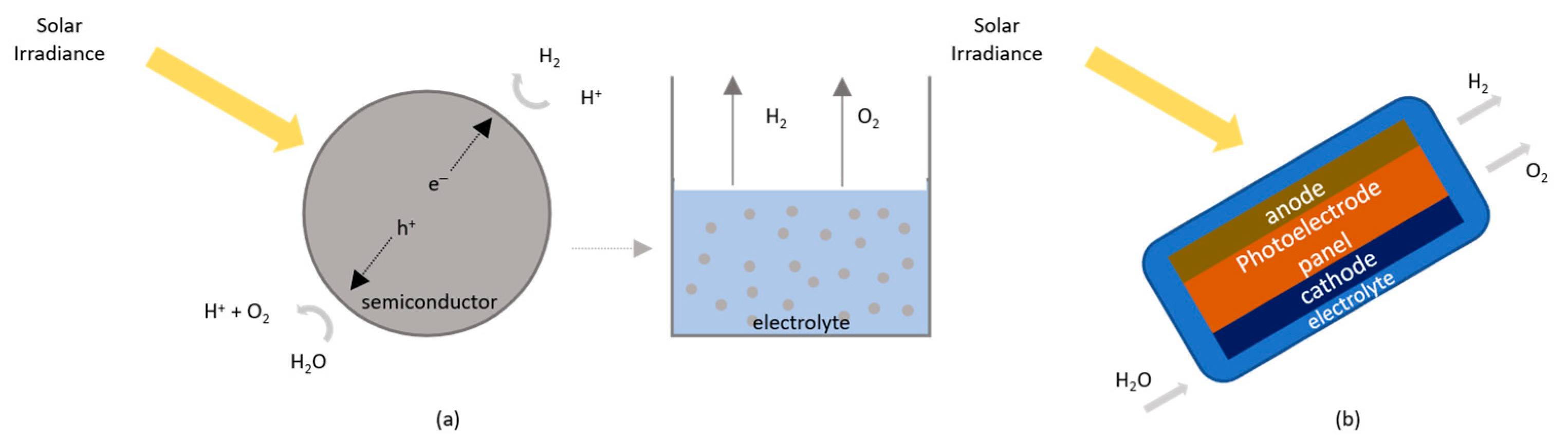
2.4. Photolytic Processes
2.5. Comparison of Hydrogen Production Technologies

| Technology | Feedstock | Energy Source | Advantages | Disadvantages | Hydrogen Classification | Efficiency (%) | LCOH (USD/kgH2) | TRL | REF |
|---|---|---|---|---|---|---|---|---|---|
| Steam reforming | Fossil fuels | Thermal |
|
| Gray | 69–85 | 0.7–2.08 | 9 | [12,23,41,57,58] |
| Steam reforming + CCS | Fossil fuels | Thermal |
|
| Blue | 55–80 | 1.2–2.27 | 8–9 | [23,27,59] |
| Partial oxidation | Fossil fuels | Thermal |
|
| Gray | 60–75 | 1.24 | 9 | [12,31,41,58] |
| Autothermal reforming | Fossil fuels | Thermal |
|
| Gray | 60–75 | 1.24 | 9 | [12,31,58] |
| Gasification | Fossil fuels | Thermal |
|
| Gray | 74–85 | 1.34–2.5 | 9 | [12,24,32,41,57,58,59] |
| Biomass | Thermal |
|
| Green | 35–50 | 1.77–2.77 | 7 | [23,24,32,33,41,57,60,61] | |
| Gasification + CCS | Fossil fuels | Thermal |
|
| Blue | 60–80 | 1.63–2.60 | 8–9 | [24,59] |
| Pyrolysis | Fossil fuels | Thermal |
|
| Turquoise | ~58 | 1.59–3.20 | 7 | [24,27,33,57,62] |
| Biomass | Thermal |
|
| Green | 35–50 | 1.25–2.20 | 7 | [12,24,32,36,60,61] | |
| Thermochemical cycles | Water | Thermal (solar) |
|
| Green | 20–55 | 7.98–8.40 | 1–3 | [23,24,37,63] |
| Thermochemical cycles | Water | Thermal (nuclear) |
|
| Purple | 20–55 | 2.17–2.63 | 1–3 | [23,24,37,63] |
| Dark fermentation | Biomass | Organic matter |
|
| Green | 60–80 | 2.15–2.57 | 5 | [12,24,39,60,61] |
| Photo-fermentation | Biomass | Solar radiation |
|
| Green | 10 | 2.37–2.83 | 4 | [12,24,39,60,61] |
| Bio-photolysis | Water | Solar radiation |
|
| Green | 10 | 1.42–2.13 | 1–3 | [12,24,39,60] |
| Electrolysis (AEL) | Water | Electric (RES) |
|
| Green | 50–78 | 2.90–14.40 (utility-scale PV in the EU and Norway) 2.20–9.40 (on and offshore wind in the EU and Norway) | 9 | [10,44,60,62,64] |
| Electrolysis (PEM) | Water | Electric (RES) |
|
| Green | 50–83 | 9 | [10,44,60,62,64] | |
| Electrolysis (AEM) | Water | Electric (RES) |
|
| Green | 45–55 | 6 | [10,44,60,62,64] | |
| Electrolysis (SOEL) | Water | Electric (RES) |
|
| Green | 57–69 | 7 | [10,44,60,62,64] | |
| Photolysis | Water | Solar radiation |
|
| Green | <12 | 10.36–18.98 | 1–3 | [12,24,41,50,51,60] |
3. Hydrogen Storage Technologies
3.1. Physical-Based Storage Technologies
3.2. Material-Based Storage Technologies
| Technology | Advantages | Disadvantages | Storage Pressure (bar) | Storage Temperature (K) | Gravimetric Capacity (%wt) | Volumetric Capacity (kg/m3) | TRL | REF | |
|---|---|---|---|---|---|---|---|---|---|
| Compressed gas hydrogen storage |
|
| 200–700 | Ambient | 1–5 | 39 (For 700 bar) | 8–9 | [65,66,67,70,71,74,75] | |
| Liquid hydrogen storage |
|
| Ambient | 20.3 | Up to 20 | 71 | 6–9 | ||
| Cryo-compressed hydrogen storage |
|
| 50–700 | 35–110 | 5–8 | 60–72 | 4–5 | ||
| Adsorption technologies | Carbon-based |
|
| 59 to 340 | 77 to Ambient | 1–10 | 16–18 | 7–8 | |
| MOF | 15 to 80 | 77 to Ambient | 2–10 | 12–45 | 2–4 | ||||
| Metal hydrides | Elemental hydrides |
|
| Ambient to 313 | Ambient | 7 (Mg) 10 (Al) | 86–109 (Mg) 148 (Al) | 7–9 | |
| Intermetallic hydrides | Ambient to 313 | Ambient | Up to 5.4 | 90–105 | 5–7 | ||||
| Complex hydrides | Ambient to 313 | Ambient | 19 (Borohydrides) | 46–121 | 4–6 | ||||
| Chemical hydrogen storage | Ammonia |
|
| Ambient | 240 | 18 | 108–120 | 7–9 | |
| Methanol | Ambient | Ambient | 12 | 95–99 | 7–9 | ||||
| LHOC | Ambient | Ambient | 1.7–17.8 | 47–65 | 4–7 | ||||
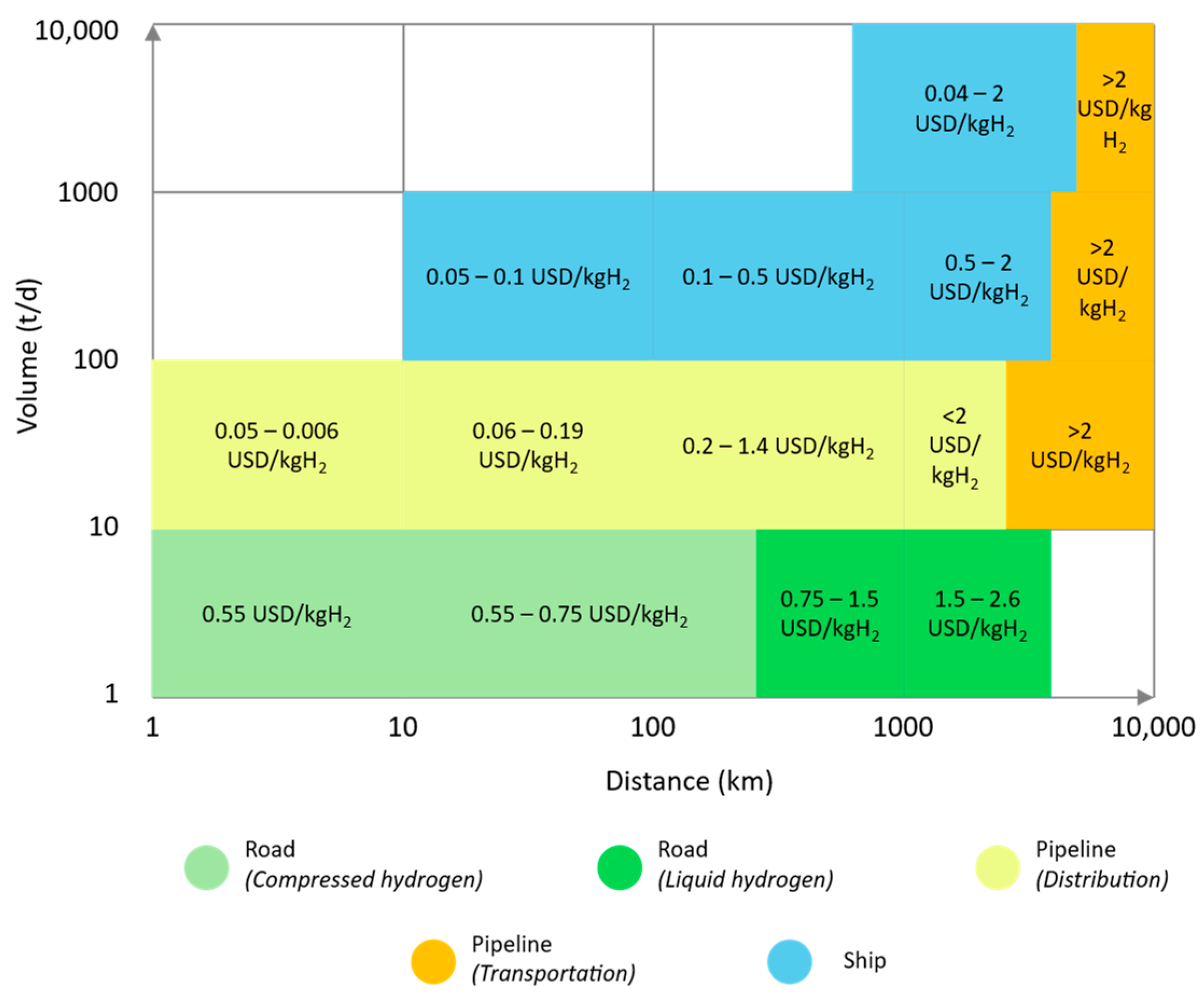
4. Hydrogen Transportation and Distribution Technologies
4.1. Transport and Distribution by Road
4.2. Transport and Distribution by Pipelines
4.3. Transport and Distribution by Ship
5. Hydrogen Applications in End-Use Sectors
5.1. Decarbonizing the Power Sector
5.2. Decarbonizing the Transport Sector
5.3. Decarbonizing Industry
5.4. Decarbonizing the Heating Sector
5.5. Overview of Hydrogen Use
6. Challenges to the Implementation of a Green Hydrogen Economy
- The investment needed to support the transition from conventional hydrogen production methods to renewable methods, as green hydrogen production technologies require high initial capital expenditures [113].
- The complexity and expenditure of the storage process resulting from hydrogen’s low volumetric density [92]. Physical-based storage is energy intensive and requires high-strength materials to handle the high-pressure values and/or cooling systems capable of achieving and maintaining low-temperature values [113,114]. Although material-based storage has shown some potential to tackle this limitation, the technology remains at a low TRL.
- The fragmentation of the current hydrogen market, which is lacking infrastructure and a consolidated regulatory framework [113]. Effective development of hydrogen economies also requires coordination and collaboration among the different players across the value chain. A purely free market approach may not foster such collaborations and could increase the risk of underinvestment in early-stage hydrogen projects and research activities, as these areas typically offer medium to long-term financial returns [113].
- The public perception of hydrogen safety may affect its acceptance [115].
7. Conclusions
Author Contributions
Funding
Institutional Review Board Statement
Informed Consent Statement
Acknowledgments
Conflicts of Interest
Abbreviations
| AEL | Alkaline water electrolysis |
| AEMEL | Anion exchange membrane water electrolysis |
| CCS | Carbon capture and storage |
| CO | Carbon monoxide |
| CO2 | Carbon dioxide |
| EU | European Union |
| FCEB | Fuel cell electric buses |
| FCEV | Fuel cell electric vehicle |
| GHG | Greenhouse gases |
| H2 | Hydrogen |
| IEA | International Energy Agency |
| IRENA | International Renewable Energy Agency |
| LCA | Life cycle assessment |
| LCOH | Levelized cost of hydrogen |
| LOHC | Liquid organic hydrogen carriers |
| LSCF | Lanthanum, strontium, cobalt, and iron |
| LSM | Lanthanum, strontium, and manganese |
| MOF | Metal–organic framework |
| PC | Photocatalytic |
| PEC | Photoelectrochemical |
| PEMEL | Polymer electrolyte membrane water electrolysis |
| PV | Photovoltaic |
| RES | Renewable energy sources |
| SAF | Sustainable aviation fuels |
| SMR | Steam methane reforming |
| SOEL | Solid oxide water electrolysis |
| SR | Steam reforming |
| VRE | Variable renewable energy |
References
- International Energy Agency. The Future of Hydrogen: Seizing Today’s Opportunities. 2019. Available online: https://www.iea.org/reports/the-future-of-hydrogen (accessed on 12 December 2024).
- International Renewable Energy Agency. Hydrogen: A Renewable Energy Perspective. 2019. Available online: https://www.irena.org/publications/2019/Sep/Hydrogen-A-renewable-energy-perspective/ (accessed on 15 January 2025).
- European Commission. The European Green Deal; European Commission: Luxembourg, 2024. [Google Scholar] [CrossRef]
- Comission, E. A Hydrogen Strategy for a Climate-Neutral Europe; European Commission: Luxembourg, 2020. [Google Scholar] [CrossRef]
- European Commission. REPowerEU Plan. 2022. Available online: https://ec.europa.eu/commission/presscorner/detail/es/ip_22_3131 (accessed on 19 January 2025).
- Desantis, D.; James, B.D.; Saur, G.; Lyubovsky, M. Cost of long-distance energy transmission by different carriers. ISCIENCE 2021, 24, 103495. [Google Scholar] [CrossRef]
- International Energy Agency. Global Hydrogen Review 2021; International Energy Agency: Paris, France, 2021. [Google Scholar] [CrossRef]
- International Energy Agency. Global Hydrogen Review 2023; International Energy Agency: Paris, France, 2023. [Google Scholar] [CrossRef]
- International Energy Agency Energy. Technology Perspectives 2023. 2023. Available online: https://www.iea.org/reports/energy-technology-perspectives-2023 (accessed on 3 February 2025).
- International Renewable Energy. Agency Making the Breakthrough, Green Hydrogen Policies and Technology Costs. 2021. Available online: https://www.irena.org/-/media/Files/IRENA/Agency/Publication/2020/Nov/IRENA_Green_Hydrogen_breakthrough_2021.pdf (accessed on 6 March 2025).
- Frieden, F.; Leker, J. Future costs of hydrogen: A quantitative review. Sustain. Energy Fuels 2024, 8, 1806–1822. [Google Scholar] [CrossRef]
- Vidas, L.; Castro, R. Recent developments on hydrogen production technologies: State-of-the-art review with a focus on green-electrolysis. Appl. Sci. 2021, 11, 11363. [Google Scholar] [CrossRef]
- Zainal, B.S.; Ker, P.J.; Mohamed, H.; Ong, H.C.; Fattah, I.M.R.; Rahman, S.M.A.; Nghiem, L.D.; Mahlia, T.M.I. Recent advancement and assessment of green hydrogen production technologies. Renew. Sustain. Energy Rev. 2024, 189, 113941. [Google Scholar] [CrossRef]
- Chelvam, K.; Hanafiah, M.M.; Woon, K.S.; Ali, K. Al A review on the environmental performance of various hydrogen production technologies: An approach towards hydrogen economy. Energy Rep. 2024, 11, 369–383. [Google Scholar] [CrossRef]
- El-Shafie, M. Hydrogen production by water electrolysis technologies: A review. Res. Eng. 2023, 20, 101426. [Google Scholar] [CrossRef]
- Gomaa, F.A.; Nada, A.A.; Gomaa, H.E.M.; El-Maghrabi, H.H. Advancing green hydrogen: Innovations and challenges in seawater electrolysis for sustainable energy production. J. Environ. Chem. Eng. 2025, 13, 115644. [Google Scholar] [CrossRef]
- Abe, J.O.; Popoola, A.P.I.; Ajenifuja, E.; Popoola, O.M. Hydrogen energy, economy and storage: Review and recommendation. Int. J. Hydrogen Energy 2019, 44, 15072–15086. [Google Scholar] [CrossRef]
- Lu, X.; Krutoff, A.C.; Wappler, M.; Fischer, A. Key influencing factors on hydrogen storage and transportation costs: A systematic literature review. Int. J. Hydrogen Energy 2025, 105, 308–325. [Google Scholar] [CrossRef]
- Wang, X.; Cheng, T.; Hong, H.; Guo, H.; Lin, X.; Yang, X.; Nie, B.; Hu, Z.; Zou, J. Challenges and opportunities in hydrogen storage and transportation: A comprehensive review. Renew. Sustain. Energy Rev. 2025, 219, 115881. [Google Scholar] [CrossRef]
- Capurso, T.; Stefanizzi, M.; Torresi, M.; Camporeale, S.M. Perspective of the role of hydrogen in the 21st century energy transition. Energy Convers. Manag. 2022, 251, 114898. [Google Scholar] [CrossRef]
- Tak, Y.C.; Paw, J.K.S.; Kadirgama, K.; Yusaf, T.; Ramasamy, D.; Sudhakar, K.; Sandhya, M.; Awad, O.I.; Zhou, B.; Pasupuleti, J.; et al. Decarbonizing the future for the transportation and aviation industries: Green hydrogen as the sustainable fuel solution. Mater. Today Sustain. 2025, 31, 101152. [Google Scholar] [CrossRef]
- Abdin, Z.; Zafaranloo, A.; Rafiee, A.; Mérida, W.; Lipiński, W.; Khalilpour, K.R. Hydrogen as an energy vector. Renew. Sustain. Energy Rev. 2020, 120, 109620. [Google Scholar] [CrossRef]
- Ji, M.; Wang, J. Review and comparison of various hydrogen production methods based on costs and life cycle impact assessment indicators. Int. J. Hydrogen Energy 2021, 46, 38612–38635. [Google Scholar] [CrossRef]
- Rasul, M.G.; Hazrat, M.A.; Sattar, M.A.; Jahirul, M.I.; Shearer, M.J. The future of hydrogen: Challenges on production, storage and applications. Energy Convers. Manag. 2022, 272, 116326. [Google Scholar] [CrossRef]
- Raimondi, P.P. Green Hydrogen: The Holy Grail of Decarbonisation?—An Analysis of the Technical and Geopolitical Implications of the Future Hydrogen Economy. FEEM Work. Pap. No. 13.2020. 2020. Available online: https://ssrn.com/abstract=3709789 (accessed on 1 April 2025).
- Maniscalco, M.P.; Longo, S.; Cellura, M.; Miccichè, G.; Ferraro, M. Critical Review of Life Cycle Assessment of Hydrogen Production Pathways. Environments 2024, 11, 108. [Google Scholar] [CrossRef]
- Hermesmann, M.; Müller, T.E. Green, Turquoise, Blue, or Grey? Environmentally friendly Hydrogen Production in Transforming Energy Systems. Prog. Energy Combust. Sci. 2022, 90, 100996. [Google Scholar] [CrossRef]
- Sikiru, S.; Oladosu, T.L.; Amosa, T.I.; Olutoki, J.O.; Ansari, M.N.M.; Abioye, K.J.; Rehman, Z.U.; Soleimani, H. Hydrogen-powered horizons: Transformative technologies in clean energy generation, distribution, and storage for sustainable innovation. Int. J. Hydrogen Energy 2024, 56, 1152–1182. [Google Scholar] [CrossRef]
- Zohuri, B. Hydrogen Energy, Callenges and Solutions for a Cleaer Future; Springer: Berlin/Heidelberg, Germany, 2019; pp. 229–257. [Google Scholar]
- Binder, M.; Kraussler, M.; Matthias Kuba, M.L. Hydrogen from Biomass Gasification; 2018; Vol. 85. Available online: https://www.ieabioenergy.com/wp-content/uploads/2019/01/Wasserstoffstudie_IEA-final.pdf (accessed on 24 January 2025).
- Nnabuife, S.G.; Ugbeh-Johnson, J.; Okeke, N.E.; Ogbonnaya, C. Present and Projected Developments in Hydrogen Production: A Technological Review. Carbon Capture Sci. Technol. 2022, 3, 100042. [Google Scholar] [CrossRef]
- Taipabu, M.I.; Viswanathan, K.; Wu, W.; Hattu, N.; Atabani, A.E. A critical review of the hydrogen production from biomass-based feedstocks: Challenge, solution, and future prospect. Process Saf. Environ. Prot. 2022, 164, 384–407. [Google Scholar] [CrossRef]
- Sánchez-Bastardo, N.; Schlögl, R.; Ruland, H. Methane Pyrolysis for Zero-Emission Hydrogen Production: A Potential Bridge Technology from Fossil Fuels to a Renewable and Sustainable Hydrogen Economy. Ind. Eng. Chem. Res. 2021, 60, 11855–11881. [Google Scholar] [CrossRef]
- Ferreiro, A.I.; Ferreira, A.F.; Fernandes, E.C.; Coelho, P. Influence of process parameters on biomass gasification: A review of experimental studies in entrained flow reactors and droptube furnaces. Biomass Bioenergy 2024, 185, 107217. [Google Scholar] [CrossRef]
- Schneider, S.; Bajohr, S.; Graf, F.; Kolb, T. State of the Art of Hydrogen Production via Pyrolysis of Natural Gas. ChemBioEng Rev. 2020, 7, 150–158. [Google Scholar] [CrossRef]
- Lopez, G.; Santamaria, L.; Lemonidou, A.; Zhang, S.; Wu, C.; Sipra, A.T.; Gao, N. Hydrogen generation from biomass by pyrolysis. Nat. Rev. Methods Prim. 2022, 2, 1–13. [Google Scholar] [CrossRef]
- Safari, F.; Dincer, I. A review and comparative evaluation of thermochemical water splitting cycles for hydrogen production. Energy Convers. Manag. 2020, 205, 112182. [Google Scholar] [CrossRef]
- Pacheco, R.; Ferreira, A.F.; Pinto, T.; Nobre, B.P.; Loureiro, D.; Moura, P.; Gouveia, L.; Silva, C.M. The production of pigments & hydrogen through a Spirogyra sp. biorefinery. Energy Convers. Manag. 2015, 89, 789–797. [Google Scholar] [CrossRef]
- Aziz, M.; Darmawan, A.; Juangsa, F.B. Hydrogen production from biomasses and wastes: A technological review. Int. J. Hydrogen Energy 2021, 46, 33756–33781. [Google Scholar] [CrossRef]
- Dzulkarnain, E.L.N.; Audu, J.O.; Wan Dagang, W.R.Z.; Abdul-Wahab, M.F. Microbiomes of biohydrogen production from dark fermentation of industrial wastes: Current trends, advanced tools and future outlook. Bioresour. Bioprocess. 2022, 9, 16. [Google Scholar] [CrossRef]
- Pal, D.B.; Singh, A.; Bhatnagar, A. A review on biomass based hydrogen production technologies. Int. J. Hydrogen Energy 2022, 47, 1461–1480. [Google Scholar] [CrossRef]
- Ferreira, A.F.; Ribeiro, L.A.; Batista, A.P.; Marques, P.A.S.S.; Nobre, B.P.; Palavra, A.M.F.; da Silva, P.P.; Gouveia, L.; Silva, C. A biorefinery from Nannochloropsis sp. microalga—Energy and CO2 emission and economic analyses. Bioresour. Technol. 2013, 138, 235–244. [Google Scholar] [CrossRef]
- Yue, M.; Lambert, H.; Pahon, E.; Roche, R.; Jemei, S.; Hissel, D. Hydrogen energy systems: A critical review of technologies, applications, trends and challenges. Renew. Sustain. Energy Rev. 2021, 146, 111180. [Google Scholar] [CrossRef]
- Shiva Kumar, S.; Lim, H. An overview of water electrolysis technologies for green hydrogen production. Energy Rep. 2022, 8, 13793–13813. [Google Scholar] [CrossRef]
- Sebbahi, S.; Assila, A.; Alaoui Belghiti, A.; Laasri, S.; Kaya, S.; Hlil, E.K.; Rachidi, S.; Hajjaji, A. A comprehensive review of recent advances in alkaline water electrolysis for hydrogen production. Int. J. Hydrogen Energy 2024, 82, 583–599. [Google Scholar] [CrossRef]
- Ishaq, H.; Dincer, I.; Crawford, C. A review on hydrogen production and utilization: Challenges and opportunities. Int. J. Hydrogen Energy 2022, 47, 26238–26264. [Google Scholar] [CrossRef]
- Sezer, N.; Bayhan, S.; Fesli, U.; Sanfilippo, A. A comprehensive review of the state-of-the-art of proton exchange membrane water electrolysis. Mater. Sci. Energy Technol. 2025, 8, 44–65. [Google Scholar] [CrossRef]
- Du, Y.; Ling, H.; Zhao, L.; Jiang, H.; Kong, J.; Liu, P.; Zhou, T. The development of solid oxide electrolysis cells: Critical materials, technologies and prospects. J. Power Sources 2024, 607, 234608. [Google Scholar] [CrossRef]
- Mulk, W.U.; Aziz, A.R.A.; Ismael, M.A.; Ghoto, A.A.; Ali, S.A.; Younas, M.; Gallucci, F. Electrochemical hydrogen production through anion exchange membrane water electrolysis: Recent progress and associated challenges in hydrogen production. Int. J. Hydrogen Energy 2024, 94, 1174–1211. [Google Scholar] [CrossRef]
- Gopinath, M.; Marimuthu, R. A review on solar energy-based indirect water-splitting methods for hydrogen generation. Int. J. Hydrogen Energy 2022, 47, 37742–37759. [Google Scholar] [CrossRef]
- Frowijn, L.S.F.; van Sark, W.G.J.H.M. Analysis of photon-driven solar-to-hydrogen production methods in the Netherlands. Sustain. Energy Technol. Assess. 2021, 48, 101631. [Google Scholar] [CrossRef]
- U.S. Department of Energy Hydrogen Production: Photoelectrochemical Water Splitting. Available online: https://www.energy.gov/eere/fuelcells/hydrogen-production-photoelectrochemical-water-splitting (accessed on 5 April 2025).
- Akyüz, E.S.; Telli, E.; Farsak, M. Hydrogen generation electrolyzers: Paving the way for sustainable energy. Int. J. Hydrogen Energy 2024, 81, 1338–1362. [Google Scholar] [CrossRef]
- Nnabuife, S.G.; Hamzat, A.K.; Whidborne, J.; Kuang, B.; Jenkins, K.W. Integration of renewable energy sources in tandem with electrolysis: A technology review for green hydrogen production. Int. J. Hydrogen Energy 2025, 107, 218–240. [Google Scholar] [CrossRef]
- Athia, N.; Pandey, M.; Sen, M.; Saxena, S. Factors Affecting the Economy of Green Hydrogen Production Pathways for Sustainable Development and Their Challenges; Springer: Berlin/Heidelberg, Germany, 2024; Volume 31, ISBN 1135602434096. [Google Scholar]
- International Energy Agency. Global Hydrogen Review 2022; International Energy Agency: Paris, France, 2022. [Google Scholar]
- Al-Qahtani, A.; Parkinson, B.; Hellgardt, K.; Shah, N.; Guillen-Gosalbez, G. Uncovering the true cost of hydrogen production routes using life cycle monetisation. Appl. Energy 2021, 281, 115958. [Google Scholar] [CrossRef]
- May, G.J.; Davidson, A.; Monahov, B. Lead batteries for utility energy storage: A review. J. Energy Storage 2018, 15, 145–157. [Google Scholar] [CrossRef]
- International Energy Agency. Global Average Levelised Cost of Hydrogen Production by Energy Source and Technology, 2019 and 2050. Available online: https://www.iea.org/data-and-statistics/charts/global-average-levelised-cost-of-hydrogen-production-by-energy-source-and-technology-2019-and-2050 (accessed on 8 April 2025).
- Megia, P.J.; Vizcaino, A.J.; Calles, J.A.; Carrero, A. Hydrogen Production Technologies: From Fossil Fuels toward Renewable Sources. A Mini Review. Energy Fuels 2021, 35, 16403–16415. [Google Scholar] [CrossRef]
- European Technology and Innovation Platform Bioenergy. Renewable Hydrogen Production from Biomass. Available online: https://www.etipbioenergy.eu/publications-and-reports (accessed on 3 April 2025).
- International Energy Agency. Hydrogen Patents for a Clean Energy Future. 2023. Available online: https://iea.blob.core.windows.net/assets/1b7ab289-ecbc-4ec2-a238-f7d4f022d60f/Hydrogenpatentsforacleanenergyfuture.pdf (accessed on 3 April 2025).
- Singla, S.; Shetti, N.P.; Basu, S.; Mondal, K.; Aminabhavi, T.M. Hydrogen production technologies—Membrane based separation, storage and challenges. J. Environ. Manag. 2022, 302, 113963. [Google Scholar] [CrossRef] [PubMed]
- Hydrogen Science Coalition. Clean Hydrogen Definition. 2022. Available online: https://h2sciencecoalition.com/briefings/clean-hydrogen-definition/ (accessed on 23 April 2025).
- Patonia, A.; Poudineh, R.; Hove, A.; Meidan, M. Hydrogen Storage for a Net-Zero Carbon Future. 2023. Available online: https://www.oxfordenergy.org/publications/hydrogen-storage-for-a-net-zero-carbon-future/ (accessed on 12 April 2025).
- Hassan, I.A.; Ramadan, H.S.; Saleh, M.A.; Hissel, D. Hydrogen storage technologies for stationary and mobile applications: Review, analysis and perspectives. Renew. Sustain. Energy Rev. 2021, 149, 111311. [Google Scholar] [CrossRef]
- Mehr, A.S.; Phillips, A.D.; Brandon, M.P.; Pryce, M.T.; Carton, J.G. Recent challenges and development of technical and techno-economic aspects for hydrogen storage, insights at different scales; A state of art review. Int. J. Hydrogen Energy 2024, 70, 786–815. [Google Scholar] [CrossRef]
- Raza, A.; Arif, M.; Glatz, G.; Mahmoud, M.; Al, M.; Alafnan, S.; Iglauer, S. A holistic overview of underground hydrogen storage: Influencing factors, current understanding, and outlook. Fuel 2022, 330, 125636. [Google Scholar] [CrossRef]
- Kumar, N.; Lee, S.-Y.; Park, S.-J. Advancements in hydrogen storage technologies: A comprehensive review of materials, methods, and economic policy. Nano Today 2024, 56, 102302. [Google Scholar] [CrossRef]
- Barthelemy, H.; Weber, M.; Barbier, F. Hydrogen storage: Recent improvements and industrial perspectives. Int. J. Hydrogen Energy 2017, 42, 7254–7262. [Google Scholar] [CrossRef]
- Usman, M.R. Hydrogen storage methods: Review and current status. Renew. Sustain. Energy Rev. 2022, 167, 112743. [Google Scholar] [CrossRef]
- Guo, L.; Su, J.; Wang, Z.; Shi, J.; Guan, X.; Cao, W.; Ou, Z. Hydrogen safety: An obstacle that must be overcome on the road towards future hydrogen economy. Int. J. Hydrogen Energy 2024, 51, 1055–1078. [Google Scholar] [CrossRef]
- Peng, T.; Wan, J.; Liu, W.; Li, J.; Xia, Y.; Yuan, G.; Jurado, M.J.; Fu, P.; He, Y.; Liu, H. Choice of hydrogen energy storage in salt caverns and horizontal cavern construction technology. J. Energy Storage 2023, 60, 106489. [Google Scholar] [CrossRef]
- Xu, Z.; Zhao, N.; Hillmansen, S.; Roberts, C.; Yan, Y. Techno-Economic Analysis of Hydrogen Storage Technologies for Railway Engineering: A Review. Energies 2022, 15, 6467. [Google Scholar] [CrossRef]
- Lin, A.; Bagnato, G. Revolutionising energy storage: The Latest Breakthrough in liquid organic hydrogen carriers. Int. J. Hydrogen Energy 2024, 63, 315–329. [Google Scholar] [CrossRef]
- Wulf, C.; Reuß, M.; Grube, T.; Zapp, P.; Robinius, M.; Hake, J.F.; Stolten, D. Life Cycle Assessment of hydrogen transport and distribution options. J. Clean. Prod. 2018, 199, 431–443. [Google Scholar] [CrossRef]
- Chu, C.; Wu, K.; Luo, B.; Cao, Q.; Zhang, H. Hydrogen storage by liquid organic hydrogen carriers: Catalyst, renewable carrier, and technology—A review. Carbon Resour. Convers. 2023, 6, 334–351. [Google Scholar] [CrossRef]
- Osman, A.I.; Nasr, M.; Eltaweil, A.S.; Hosny, M.; Farghali, M.; Al-Fatesh, A.S.; Rooney, D.W.; Abd El-Monaem, E.M. Advances in hydrogen storage materials: Harnessing innovative technology, from machine learning to computational chemistry, for energy storage solutions. Int. J. Hydrogen Energy 2024, 67, 1270–1294. [Google Scholar] [CrossRef]
- Faye, O.; Szpunar, J.; Eduok, U. A critical review on the current technologies for the generation, storage, and transportation of hydrogen. Int. J. Hydrogen Energy 2022, 47, 13771–13802. [Google Scholar] [CrossRef]
- Hurskainen, M.; Ihonen, J. Techno-economic feasibility of road transport of hydrogen using liquid organic hydrogen carriers. Int. J. Hydrogen Energy 2020, 45, 32098–32112. [Google Scholar] [CrossRef]
- Reuß, M.; Dimos, P.; Léon, A.; Grube, T.; Robinius, M.; Stolten, D. Hydrogen road transport analysis in the energy system: A case study for germany through 2050. Energies 2021, 14, 3166. [Google Scholar] [CrossRef]
- International Renewable Energy Angency. Global Hydrogen Trade to Meet the 1.5 °C Climate Goal: Part II—Technology Review of Hydrogen Carriers. 2022. Available online: https://www.irena.org/-/media/Files/IRENA/Agency/Publication/2022/Apr/IRENA_Global_Trade_Hydrogen_2022.pdf (accessed on 21 March 2025).
- Muhammed, N.S.; Gbadamosi, A.O.; Epelle, E.I.; Abdulrasheed, A.A.; Haq, B.; Patil, S.; Al-Shehri, D.; Kamal, M.S. Hydrogen production, transportation, utilization, and storage: Recent advances towards sustainable energy. J. Energy Storage 2023, 73, 109207. [Google Scholar] [CrossRef]
- EPCM Challenges in Hydrogen Pipeline Design. Available online: https://epcmholdings.com/challenges-in-hydrogen-pipeline-design/ (accessed on 24 May 2025).
- Khan, M.A.; Young, C.; Layzell, D.B. The Techno-Economics of Hydrogen Pipelines. Transit. Accel. Tech. Briefs 2021, 1, 1–40. Available online: www.transitionaccelerator.ca (accessed on 15 March 2025).
- Sofian, M.; Haq, M.B.; Al Shehri, D.; Rahman, M.M.; Muhammed, N.S. A review on hydrogen blending in gas network: Insight into safety, corrosion, embrittlement, coatings and liners, and bibliometric analysis. Int. J. Hydrogen Energy 2024, 60, 867–889. [Google Scholar] [CrossRef]
- Raj, A.; Larsson, I.A.S.; Ljung, A.L.; Forslund, T.; Andersson, R.; Sundström, J.; Lundström, T.S. Evaluating hydrogen gas transport in pipelines: Current state of numerical and experimental methodologies. Int. J. Hydrogen Energy 2024, 67, 136–149. [Google Scholar] [CrossRef]
- Zhang, H.; Zhao, J.; Li, J.; Yu, B.; Wang, J.; Lyu, R.; Xi, Q. Research progress on corrosion and hydrogen embrittlement in hydrogen–natural gas pipeline transportation. Nat. Gas Ind. B 2023, 10, 570–582. [Google Scholar] [CrossRef]
- Bouledroua, O.; Zelmati, D.; Hafsi, Z.; Djukic, M.B. Hydrogen embrittlement effects on remaining life and fatigue crack growth rate in API 5L X52 steel pipelines under cyclic pressure loading. Eng. Fail. Anal. 2024, 166, 108917. [Google Scholar] [CrossRef]
- Jubica; Claeys, L.; Laureys, A.; De Waele, W.; Schweicher, J.; Depover, T.; Verbeken, K. Gaseous inhibitors: A comprehensive overview on mitigating hydrogen embrittlement in pipeline steels. Int. J. Hydrogen Energy 2024, 136, 630–642. [Google Scholar] [CrossRef]
- Weikl, M.; Peschel, A. Industrial view on hydrogen carriers for intercontinental transport. Curr. Opin. Green Sustain. Chem. 2023, 44, 100843. [Google Scholar] [CrossRef]
- Kamran, M.; Turzy, M. Exploring hydrogen energy systems: A comprehensive review of technologies, applications, prevailing trends, and associated challenges’ ski. J. Energy Storage 2024, 96, 112601. [Google Scholar] [CrossRef]
- International Renewable Energy Angency. Innovation landscape Brief: Renewable Power-to-Hydrogen, International Renewable Energy. 2019. Available online: https://www.irena.org/-/media/Files/IRENA/Agency/Publication/2019/Sep/IRENA_Power-to-Hydrogen_Innovation_2019.pdf (accessed on 30 January 2025).
- Montazerinejad, H.; Eicker, U.; Ahmadi, P. Renewable fuel-powered micro-gas turbine and hydrogen fuel cell systems: Exploring scenarios of technology, control, and operation. Energy Convers. Manag. 2024, 319, 118944. [Google Scholar] [CrossRef]
- Zhu, Y.; Tomsovic, K. Development of models for analyzing the load-following performance of microturbines and fuel cells. Electr. Power Syst. Res. 2002, 62, 1–11. [Google Scholar] [CrossRef]
- Raimondi, G.; Spazzafumo, G. Exploring Renewable Energy Communities integration through a hydrogen Power-to-Power system in Italy. Renew. Energy 2023, 206, 710–721. [Google Scholar] [CrossRef]
- Culatra Island: Hydrogen in a Renewable Energy Community—H2tALENT. Available online: https://h2talent.eu/case-studies/culatra-island-hydrogen-in-a-renewable-energy-community/ (accessed on 10 July 2025).
- Europe, H. Hydrogen Infraestructure: The Recipe for a Hydrogen Grid Plan. Available online: https://hydrogeneurope.eu/policy-priorities/position-papers/ (accessed on 22 June 2025).
- International Renewable Energy Agency. Hydrogen from Renewable Power: Technology Outlook for the Energy Transition. 2018. Available online: https://www.irena.org/publications/2018/Sep/Hydrogen-from-renewable-power (accessed on 2 April 2025).
- Hydrogen Council Roadmap Towards Zero Emissions. 2021, p. 26. Available online: https://hydrogencouncil.com/en/roadmap-towards-zero-emissions-bevs-and-fcevs/ (accessed on 3 December 2024).
- Roy, A.; Pramanik, S. A review of the hydrogen fuel path to emission reduction in the surface transport industry. Int. J. Hydrogen Energy 2024, 49, 792–821. [Google Scholar] [CrossRef]
- Hydrogen Europe. How Hydrogen Can Help the Maritime. Policy Paper. 2021. Available online: https://www.hydrogeneurope.eu/wp-content/uploads/2021/11/How-hydrogen-can-help-decarbonise-the-maritime-sector_final.pdf (accessed on 22 May 2025).
- Yusaf, T.; Faisal Mahamude, A.S.; Kadirgama, K.; Ramasamy, D.; Farhana, K.; Dhahad, H.A.; Abu Talib, A.R. Sustainable hydrogen energy in aviation—A narrative review. Int. J. Hydrogen Energy 2024, 52, 1026–1045. [Google Scholar] [CrossRef]
- Eyberg, V.; Dieterich, V.; Bastek, S.; Dossow, M.; Spliethoff, H.; Fendt, S. Techno-economic assessment and comparison of Fischer–Tropsch and Methanol-to-Jet processes to produce sustainable aviation fuel via Power-to-Liquid. Energy Convers. Manag. 2024, 315, 118728. [Google Scholar] [CrossRef]
- Abid, H.; Skov, I.R.; Mathiesen, B.V.; Østegaard, P.A. Standalone and system-level perspectives on hydrogen-based sustainable aviation fuel pathways for Denmark. Energy 2025, 320, 135450. [Google Scholar] [CrossRef]
- European Parliament Scientific Foresight Unit. The Potential of Hydrogen for Decarbonising EU Industry. 2021. Available online: https://www.europarl.europa.eu/thinktank/en/document/EPRS_STU(2021)697199 (accessed on 12 December 2024).
- Shen, J.; Zhang, Q.; Tian, S.; Li, X.; Liu, J.; Tian, J. The role of hydrogen in iron and steel production: Development trends, decarbonization potentials, and economic impacts. Int. J. Hydrogen Energy 2024, 92, 1409–1422. [Google Scholar] [CrossRef]
- Arras, M.; Jeandey, T.-F.; He, Y.; Gupta, P.; Li, Z.; Ma, L. Decarbonizing China’s iron and steel industry: Hydrogen-based mitigation pathway and techno-economic implications. Int. J. Hydrogen Energy 2025, 154, 149946. [Google Scholar] [CrossRef]
- Zhen, Z.; Li, B.; Ou, X.; Zhou, S. How hydrogen can decarbonize the chemical industry in China: A review based on the EIC–TER industrial assessment framework. Int. J. Hydrogen Energy 2024, 60, 1345–1358. [Google Scholar] [CrossRef]
- Bararzadeh Ledari, M.; Khajehpour, H.; Akbarnavasi, H.; Edalati, S. Greening steel industry by hydrogen: Lessons learned for the developing world. Int. J. Hydrogen Energy 2023, 48, 36623–36649. [Google Scholar] [CrossRef]
- Voglar, J.; Likozar, B. Critical perspective on green hydrogen-based seasonal operation of energy-intensive industry sectors with solid products. Int. J. Hydrogen Energy 2024, 93, 910–924. [Google Scholar] [CrossRef]
- Pleshivtseva, Y.; Derevyanov, M.; Pimenov, A.; Rapoport, A. Comparative analysis of global trends in low carbon hydrogen production towards the decarbonization pathway. Int. J. Hydrogen Energy 2023, 48, 32191–32240. [Google Scholar] [CrossRef]
- Boretti, A.; Pollet, B.G. Hydrogen economy: Paving the path to a sustainable, low-carbon future. Int. J. Hydrogen Energy 2024, 93, 307–319. [Google Scholar] [CrossRef]
- Kovač, A.; Paranos, M.; Marciuš, D. Hydrogen in energy transition: A review. Int. J. Hydrogen Energy 2021, 46, 10016–10035. [Google Scholar] [CrossRef]
- Eljack, F.; Kazi, M.K. Prospects and Challenges of Green Hydrogen Economy via Multi-Sector Global Symbiosis in Qatar. Front. Sustain. 2020, 1, 612762. [Google Scholar] [CrossRef]


Disclaimer/Publisher’s Note: The statements, opinions and data contained in all publications are solely those of the individual author(s) and contributor(s) and not of MDPI and/or the editor(s). MDPI and/or the editor(s) disclaim responsibility for any injury to people or property resulting from any ideas, methods, instructions or products referred to in the content. |
© 2025 by the authors. Licensee MDPI, Basel, Switzerland. This article is an open access article distributed under the terms and conditions of the Creative Commons Attribution (CC BY) license (https://creativecommons.org/licenses/by/4.0/).
Share and Cite
Coelho, M.S.; Gaspar, G.; Surra, E.; Coelho, P.J.; Ferreira, A.F. Systematic Analysis of the Hydrogen Value Chain from Production to Utilization. Appl. Sci. 2025, 15, 8242. https://doi.org/10.3390/app15158242
Coelho MS, Gaspar G, Surra E, Coelho PJ, Ferreira AF. Systematic Analysis of the Hydrogen Value Chain from Production to Utilization. Applied Sciences. 2025; 15(15):8242. https://doi.org/10.3390/app15158242
Chicago/Turabian StyleCoelho, Miguel Simão, Guilherme Gaspar, Elena Surra, Pedro Jorge Coelho, and Ana Filipa Ferreira. 2025. "Systematic Analysis of the Hydrogen Value Chain from Production to Utilization" Applied Sciences 15, no. 15: 8242. https://doi.org/10.3390/app15158242
APA StyleCoelho, M. S., Gaspar, G., Surra, E., Coelho, P. J., & Ferreira, A. F. (2025). Systematic Analysis of the Hydrogen Value Chain from Production to Utilization. Applied Sciences, 15(15), 8242. https://doi.org/10.3390/app15158242