Article

Digital Twins for Intelligent Vehicle-to-Grid Systems: A Multi-Physics EV Model for AI-Based Energy Management

by
Michela Costa
1,2,* and
Gianluca Del Papa
1
1
National Research Council, Institute of Science and Technology for Sustainable Energy and Mobility, Via Guglielmo Marconi, 4, 80125 Naples, Italy
2
DG Twin S.r.l., c/o Campania NewSteel, Via Coroglio, 57, 80124 Naples, Italy
*
Author to whom correspondence should be addressed.
Appl. Sci. 2025, 15(15), 8214; https://doi.org/10.3390/app15158214
Submission received: 14 June 2025 / Revised: 10 July 2025 / Accepted: 17 July 2025 / Published: 23 July 2025
(This article belongs to the Special Issue Applications of Artificial Intelligence in the Novel Power System)

Abstract

Featured Application

The presented model is intended for integration within model-based systems engineering as applied to V2X implementation in the power system.

Abstract

This paper presents a high-fidelity multi-physics dynamic model for electric vehicles, serving as a fundamental building block for intelligent vehicle-to-grid (V2G) integration systems. The model accurately captures complex vehicle dynamics of the powertrain, battery, and regenerative braking, enabling precise energy consumption evaluation, including in AI-driven V2G scenarios. Validated using real-world data from a Citroën Ami operating on urban routes in Naples, Italy, it achieved exceptional accuracy with a root mean square error (RMSE) of 1.28% for dynamic state of charge prediction. This robust framework provides an essential foundation for AI-driven digital twin technologies in V2G applications, significantly advancing sustainable transportation and smart grid integration through predictive simulation. Its versatility supports diverse fleet applications, from residential energy management and coordinated charging optimization to commercial car sharing operations, leveraging backup power during peak demand or grid outages, so to maximize distributed battery storage utilization.

1. Introduction

The global transition toward sustainable transportation and clean energy systems has positioned battery energy storage systems (BESSs) as critical components in the evolution of modern power grids [1]. Within this context, electric vehicles (EVs) are increasingly recognized for their dual potential—particularly given that they remain parked for significant portions of each day—to store excess electricity generated by renewable sources and provide power during peak demand periods [2].
This emerging capability has fundamentally transformed the traditional role of vehicles from mere transportation devices into active participants in the energy ecosystem, enabling bidirectional energy exchange with electrical infrastructure through Vehicle-to-Grid (V2G) technologies [3]. While the integration of EVs into smart grids presents unprecedented opportunities, it also introduces significant challenges that demand sophisticated modelling and simulation tools to effectively monitor and optimize future deployments [4,5].
The digital twin technology offers a revolutionary solution to these modelling challenges by creating virtual replicas of physical systems that enable real-time monitoring, analysis, and predictive capabilities [6]. Building on this foundation, the authors have successfully applied digital twin technology across various micro-grid studies and implementations, notably within the PLATOON H2020 EU-funded project [7] and the Smart Mobility Hub Italian initiative, funded by the Italian Ministry of Enterprises and Made in Italy [8]. When applied to electric vehicle and smart grid integration, digital twins unlock exceptional opportunities for understanding complex energy flow patterns, optimizing charging strategies, and enhancing grid stability through intelligent energy management [9,10]. Moreover, these virtual representations may continuously learn from real-world data, adapt to evolving conditions, and generate valuable insights that inform optimization and control strategies [11].
The foundation for this integration lies in smart grid technology itself, which represents a revolutionary advancement in electrical network infrastructure. By utilizing digital communication and automation, smart grids can detect and respond dynamically to changes in energy supply and demand [12]. These intelligent systems facilitate real-time monitoring, analysis, and management of entire electrical networks while seamlessly integrating distributed energy resources to enhance overall system efficiency [13]. When EVs are incorporated into this smart grid infrastructure, they create a sophisticated ecosystem simultaneously serving multiple critical functions: acting as energy consumers during charging operations, functioning as distributed energy storage systems when parked, and operating as potential energy suppliers [14].
The significance of EV integration extends far beyond simple load addition to the electrical grid. Modern EVs, equipped with advanced battery systems and power electronic interfaces, in fact, spend approximately 90–95% of their operational time parked at various locations with potential charging infrastructure access [15]. This substantial idle time presents remarkable opportunities for grid support services, including peak load management and renewable energy integration [16]. Through coordinated fleet management via intelligent digital twin systems, EVs can provide ancillary services that enhance grid stability and reliability while delivering economic benefits to vehicle owners [17].
On the other hand, it is to be considered that widespread EV adoption introduces critical technical challenges for the grid (grid-to-vehicle, G2V): uncoordinated charging of large vehicle populations can create significant demand peaks that stress existing infrastructure and potentially compromise system reliability [18]. Furthermore, the intermittent and unpredictable nature of individual charging patterns, driven by diverse battery features, mobility needs, and user preferences, significantly complicates grid planning and operation [19].
To address these complexities, artificial intelligence techniques have emerged as transformative tools for enhancing power system efficiency and reliability [20]. AI-powered algorithms enable advanced predictive analytics, energy flow optimization, and intelligent management of distributed resources, making them particularly well-suited for V2G implementation [21]. Machine learning approaches can process vast datasets encompassing EV charging patterns, grid conditions, and renewable generation to optimize scheduling and dispatch decisions in real-time [22]. However, the effectiveness of these AI applications fundamentally depends on accurate, validated models that provide reliable energy consumption predictions of EVs over real use profiles, for both algorithm training and final robust operational deployment.
When combined with AI algorithms, digital twin technology creates a powerful framework for V2G optimization: virtual replicas can simulate diverse scenarios, predict system behaviour under varying conditions, and refine control strategies before real-world implementation [23]. The capacity to test and validate algorithms in virtual environments reduces operational risks while enabling rapid prototyping of innovative energy management approaches [24].
The intricate nature of EV–grid interactions, therefore, demands comprehensive simulation tools capable of modelling multifaceted relationships among vehicles, charging infrastructure, and power systems [25]. Effective digital twin platforms must accurately represent vehicle behaviour patterns, charging dynamics, and grid response characteristics across various operational scenarios [26]. Such capabilities are essential for evaluating the technical and economic feasibility of integration strategies, optimizing infrastructure deployment, and developing robust control algorithms for large-scale implementation [27]. For electric vehicles specifically, multi-physics modelling approaches prove particularly crucial in capturing complex interactions between electrical, thermal, and mechanical systems [28]. These models account for battery electrochemical dynamics, thermal management systems, power electronics behaviour, and mechanical drivetrain characteristics to deliver accurate performance and energy consumption predictions [29]. Developing high-fidelity multi-physics models remains fundamental for creating reliable digital twins capable of supporting sophisticated AI-based optimization algorithms [30,31].
This work developed and validated a high-fidelity multi-physics EV model, serving as a fundamental building block for digital twin-enabled Vehicle-to-Grid (V2G) systems. Utilizing AVL CRUISETM M, this framework accurately captures complex EV electrical, thermal, and mechanical interactions. Experimentally validated with real urban driving data from Naples, Italy, the model demonstrates exceptional accuracy, proving its reliability for intelligent V2G applications and providing a basis for AI-driven energy management. Addressing the complexities of integrating EVs with power systems, computational scheduling methods have evolved to coordinate such systems [32]. Despite advancements in EV modelling and V2G, a notable gap persists in high-fidelity, multi-physics EV models rigorously validated with real-world data. Specifically, foundational ‘computational engines’ within comprehensive digital twin architectures for AI-driven energy management in dynamic V2G scenarios are lacking. Existing approaches often sacrifice fidelity for speed, limiting predictive accuracy.
Our main contributions to filling these gaps are:
  • Development and comprehensive validation of a high-fidelity multi-physics EV model, accurately capturing powertrain, battery, and regenerative braking dynamics, against real-world driving data.
  • Establishment of this validated EV model as a core component within a digital twin framework, providing an essential physical representation for advanced AI-based energy management in V2G systems.
  • Demonstration of the model’s accuracy and reliability in predicting EV energy consumption and SoC under diverse real urban driving conditions, which is crucial for intelligent V2G optimization.
The remainder of this paper is organized as follows: Section 2 details a new digital twin architecture suitable for exploiting the advantages of the developed multi-physics EV model to optimise V2G systems. Section 3 outlines the main model features and the validation methodology. Section 4 presents the results and discusses the model’s performance. Finally, Section 5 concludes the paper and highlights future research directions.
Into detail, Section 2 provides a detailed theoretical background for the proposed intelligent Vehicle-to-Grid (V2G) system, focusing on its digital twin architecture and the underlying multi-physics electric vehicle (EV) model. The overall digital twin architecture is described through its distinct layers, clarifying how real-world data is integrated and processed to enable predictive capabilities. Furthermore, the intricate structure of the multi-physics EV model is thoroughly explained, detailing its sub-models and their interactions that capture electrical, thermal, and mechanical dynamics. The data flow within the entire system, from sensor inputs to model outputs and their use in energy management, is also comprehensively elaborated to ensure a clear understanding of the framework’s operation.

2. Digital Twin Technology for V2G

2.1. Digital Twin Architecture and Implementation Framework

The implementation of the digital twin technology for electric vehicle systems requires a structured, multi-layered architecture that facilitates real-time interactions between physical and virtual components. Recent advances in distributed energy systems have highlighted the significant impact of artificial intelligence on the planning and operation of smart grids [33], making digital twin architectures essential for managing the complex interactions between EVs and the grid infrastructure. This architecture consists of four primary layers that work synergistically to enable comprehensive system monitoring and control.
The physical layer encompasses the actual electric vehicle with its embedded sensors, control units, and communication interfaces. This layer continuously generates operational data, including battery state, energy consumption patterns, location information, charging status, and environmental conditions. The data collection framework must be robust enough to handle the dynamic nature of vehicle operations while maintaining data integrity across diverse operating conditions.
The communication and data acquisition layer serves as the critical interface between physical and digital systems. This layer manages bidirectional data flow through various communication protocols, including cellular networks, WiFi, and dedicated short-range communications (DSRC). The implementation must ensure low-latency data transmission while maintaining security protocols to protect sensitive vehicle and user information.
The digital model layer represents the core computational engine where the virtual replica of the physical vehicle resides. This layer processes incoming data streams, executes multi-physics simulations, and generates predictive insights based on validated mathematical models. The model layer must be capable of real-time parameter adjustment and adaptive learning to maintain accuracy across varying operational scenarios.
The application service layer provides the interface for end-users and system operators, delivering actionable insights, control commands, and optimization recommendations. This layer integrates with broader energy management systems and smart grid infrastructure to enable coordinated V2G operations. The integration of electric vehicles into smart grids requires sophisticated algorithms for energy management between V2G and G2V operations [34], which are facilitated through this application layer architecture.
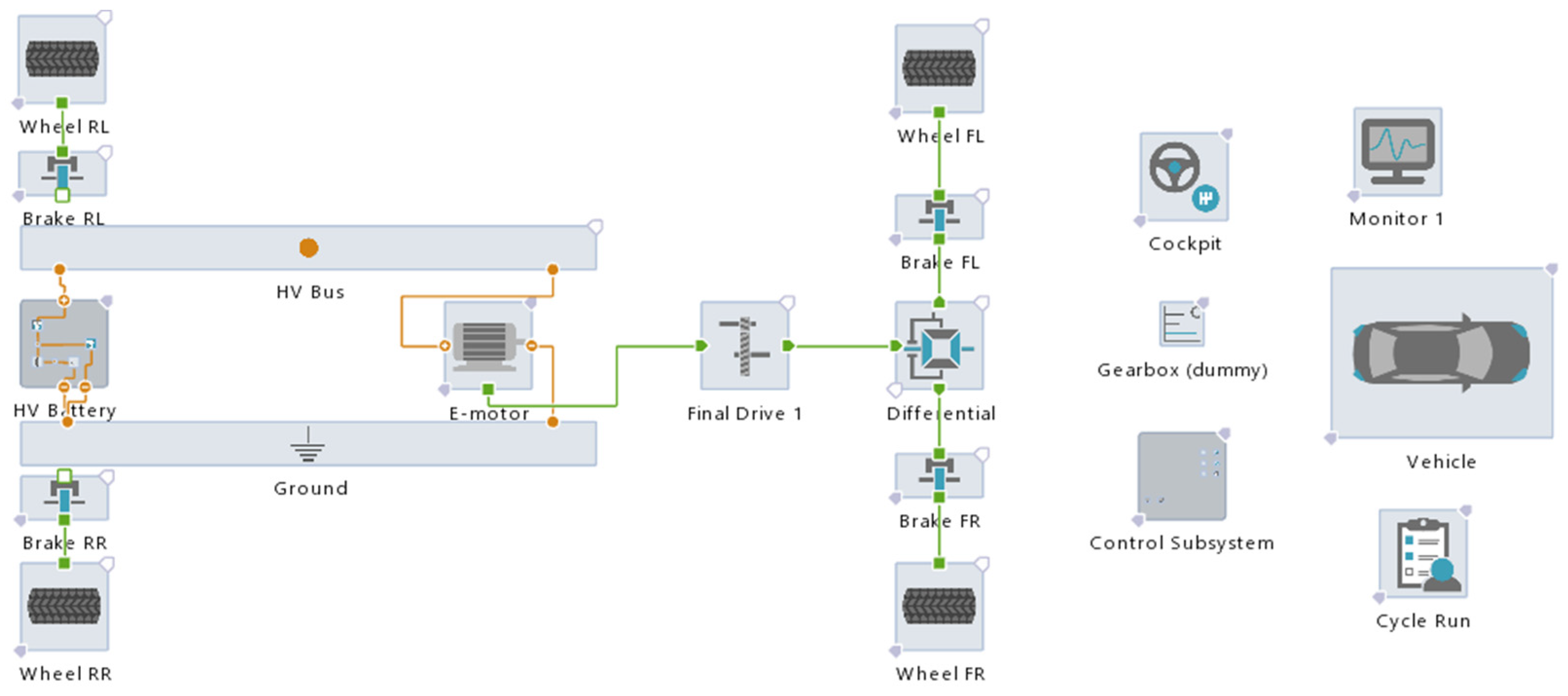
The multi-physics electric vehicle model developed in this work serves as a fundamental building block within the digital model layer of the proposed digital twin architecture. Specifically, the validated AVL CRUISE™ M model operates as a specialized component of the computational engine that can process real-time data streams from the physical layer and generates predictive insights for the application service layer. The EV model functions primarily as a tool for effective energy consumption evaluation of electric vehicles over real use profiles, providing the essential foundation for AI-driven energy management algorithms.
The integration mechanism works as follows: (1) Real-time vehicle sensor data (battery voltage, current, temperature, GPS coordinates) are collected through the communication and data acquisition layer; (2) These data streams are fed into the digital model layer where our multi-physics model performs parameter adaptation and state estimation; (3) The model executes forward simulations to predict energy consumption, optimal charging strategies, and grid interaction opportunities; (4) Results are propagated to the application service layer where AI algorithms utilize these predictions for V2G optimization decisions.
This tight integration ensures that the digital twin maintains synchronization with the physical vehicle while providing the computational fidelity necessary for sophisticated energy management algorithms. The 1.28% RMSE accuracy demonstrated in our validation directly translates to reliable state estimation within the digital twin framework, enabling confident decision-making in real-world V2G applications.

2.2. Real-Time Data Integration and Processing

The effectiveness of digital twins fundamentally depends upon data integration mechanisms that can process heterogeneous data streams while maintaining temporal consistency and ensuring quality. For EV digital twins, this involves managing data from multiple sources, including onboard vehicle sensors, charging infrastructure systems, grid monitoring devices, weather stations, and traffic management systems.
The data integration framework must address several critical challenges: temporal synchronization between different data sources operating at varying sampling rates, data quality assurance through validation and filtering algorithms, and scalability to accommodate large-scale fleet operations. Advanced filtering techniques, including Kalman filters and machine learning-based anomaly detection, can be essential for maintaining data integrity in noisy operational environments.
On the other hand, adaptive model calibration represents a crucial aspect of real-time data integration, where model parameters can be continuously adjusted based on observed vehicle behaviour. This process involves comparing predicted vs. actual performance metrics and implementing feedback mechanisms to minimize prediction errors. The optimization of demand-response and load balancing in smart EV charging networks using AI-integrated blockchain frameworks has demonstrated significant improvements in handling these complex calibration processes [35]. The calibration algorithms must be computationally efficient to enable real-time operation while maintaining model accuracy across diverse operating conditions.
In the specific case considered here, a straightforward implementation can employ Extended Kalman Filters for state estimation, particularly for battery state-of-charge estimation where sensor accuracy is compromised during dynamic driving conditions. Battery SoC sensors are notoriously imprecise during acceleration and braking events when current fluctuations affect measurement accuracy. The Extended Kalman Filter addresses this limitation by combining the validated multi-physics model predictions with real sensor data, weighing physical model predictions more heavily than unreliable sensor readings during transient conditions, then continuously adjusting the state estimate as conditions stabilize. This model–sensor fusion approach provides accurate and stable SoC estimation, which is crucial for determining optimal timing for charging and discharging energy to the grid in V2G applications.

2.3. Predictive Analytics and Optimization Capabilities

Digital twin platforms for electric mobility may leverage advanced predictive analytics to enable proactive system management and optimization. These capabilities extend beyond simple data visualization to provide business insights for energy management, maintenance planning, and operational optimization.
Generally speaking, energy consumption prediction for EV utilizes historical data patterns, route information, and environmental conditions to forecast future energy requirements. This prediction can be used for intelligent pre-conditioning of battery systems, optimal route planning, and strategic charging schedule optimization. Machine learning algorithms, particularly recurrent neural networks and time series analysis methods, prove particularly effective for capturing the complex relationships between energy consumption data collected under real driving patterns and environmental conditions. As an alternative, the model-based approach presented here can be used for battery discharge calculations over real use profiles, offering high-fidelity predictions that may also complement data-driven methods.
On the other hand, grid interaction optimization represents a critical application area where digital twins can analyse grid conditions, electricity pricing and vehicle availability to overall optimize V2G operations. This involves complex multi-objective optimization considering factors such as grid stability requirements, user mobility needs, energy consumptions and costs and battery health preservation. Digital twins for future power systems indicate substantial potential for transforming electrical grid operations, with particular emphasis on sustainability and security enhancements [36]. These can therefore play a fundamental role in V2G deployment.
The here presented multi-physics model can be utilized in two complementary ways for AI optimization of V2G systems, both in the design phase and in the digital twin real-world implementation as in the following:
  • For neural network training, the model generates high-fidelity simulation data through thousands of diverse operational scenarios, enabling networks to learn complex relationships between driving conditions and energy consumption. Once trained, these networks can provide real-time predictions with millisecond response times, although they may require periodic retraining if vehicle characteristics change or evolve (such as due to battery deterioration).
  • Alternatively, the model can serve as a simulation environment for reinforcement learning algorithms, where virtual agents experiment with different charging and discharging strategies while receiving performance feedback. This approach offers adaptive learning capabilities that can automatically adjust to changes in vehicle characteristics but require computationally intensive training periods.
The model accuracy is crucial for both modalities, ensuring that both training data for neural networks and feedback for reinforcement learning are sufficiently reliable to develop robust optimization strategies for V2G optimisation.

2.4. Integration with Smart Grid Infrastructure

The integration of EV digital twins with smart grid infrastructure creates opportunities for coordinated energy management that benefits both individual vehicle owners and the broader electrical system. This integration requires sophisticated communication protocols and standardized interfaces to enable seamless data exchange between vehicle systems and grid management platforms.
Distributed energy resource management enables electric vehicles to participate in grid services such as frequency regulation, voltage support, and peak load management. Digital twins provide the necessary real-time modelling capabilities to predict vehicle availability, energy capacity, and optimal participation strategies for different grid services. This participation can provide economic benefits to vehicle owners while contributing to grid stability and renewable energy integration.
Demand response optimization utilizes digital twin predictions to coordinate charging activities across vehicle fleets, minimizing grid stress during peak demand periods while ensuring vehicle availability for transportation needs. Advanced optimization algorithms consider factors such as time-of-use electricity pricing, renewable energy availability, and individual user preferences to develop optimal charging strategies.
Renewable energy integration is facilitated through digital twin platforms that can predict renewable energy generation patterns and coordinate vehicle charging to maximize utilization of clean energy resources. This capability is particularly valuable for integrating intermittent renewable sources such as solar and wind power into the transportation sector. The role of AI in advancing smart, sustainable, and secure energy systems has positioned digital twins as fundamental components for next-generation grid management [37]. In addition, researchers are exploring advanced energy management strategies within electricity markets, leveraging game-theoretical methods as discussed by Cheng et al. [38] to model strategic interactions between EVs and the grid, optimizing energy flow and grid stability.
The digital twin framework, therefore, can have a broad applicability since it provides the necessary modelling and prediction capabilities to enable these advanced integration scenarios while maintaining system reliability and user satisfaction.

3. Multi-Physics Electric Vehicle Modelling and Validation

3.1. AVL CRUISE™ M Vehicle Simulation Platform

AVL CRUISE™ M is an advanced multi-physics simulation platform developed by AVL for the analysis and optimization of mobile systems, specifically vehicles. It has been primarily utilized in the automotive sector to model, simulate, and validate conventional, electric, hybrid, and fuel cell propulsion systems (otherwise referred to as powertrains). The software adopts a modular approach based on an extensive library of physical and logical components (batteries, motors—both electric and internal combustion engines—brakes, wheels, differentials, cockpit, controllers, etc.) that can be easily combined to construct customized mobile system architectures.
CRUISE M is useful for conducting continuous-time dynamic simulations, accounting for mechanical, thermal, electrical, and environmental signals. It supports the integration of custom functions in C programming language and enables interactions between physical models and control strategies. It is compatible with co-simulation environments (e.g., MATLAB/Simulink), Hardware-in-Loop (HiL) and Safety Integrity Loop (SiL) systems. The utilization of AVL CRUISETM M software (v. 2024 R2) lends itself optimally to vehicle representation due to the flexibility offered by its components, which can be characterized at various levels of complexity based on available data.
The following presents the vehicle model developed within the framework of the SmartDP4Move project. More specifically, the main components selected for representing the different constituent elements of the vehicle’s mechanical and electrical architecture are presented, highlighting their mechanical, electrical, and logical connections.

3.2. Vehicle Model Development

Vehicle modelling is accomplished through the physical, mechanical (shown in green in Figure 1) and/or electrical (shown in orange in Figure 1) connection of the main components (hereinafter defined as “types”) that characterize the vehicle’s physical structure. Figure 1 presents the main schematic of the developed vehicle model.
It is possible to distinguish different elements—subdivided into different groups—including those necessary for the constitution of the vehicle model, understood as a set of mechanical and electrical elements (hereinafter defined as “physical vehicle types”) and elements useful for managing its operation from a logical and actuative perspective (hereinafter defined as “functional types”), as well as elements useful for describing environmental variables (e.g., the path followed through speed and altitude) and input elements (hereinafter defined as “input types”).
The following is a list of elements according to the three categories just described.
  • Group of “Physical vehicle types”:
    • n°1 type representative of the vehicle—defined as “Vehicle”;
    • n°4 types representative of the wheel—defined as “Wheel”; the additional characteristic (“FL”, “FR”, “RL”, “RR”) identifies the wheel position relative to the vehicle’s view (e.g., “FL” stands for “Front Left”);
    • n°4 types representative of brakes—defined as “Brake”. As for wheels, the subsequent designation identifies the position relative to the vehicle’s view;
    • n°1 type representative of the differential—defined as “Differential”;
    • n°1 type representative of motion transmission—defined as “Final driver 1”;
    • n°1 type representative of the electric motor—defined as “E-Motor”;
    • n°1 subgroup representative of the battery element—defined as “HV Battery”, within which other types appear, including the type representative of the battery—defined as “Module 1”.
  • Group of “Functional types”:
    • n°1 type representative of driver behaviour during driving and the gear change method, whether manual or automatic—defined as “Cockpit”;
    • n°1 subgroup representative of all functional controls and operating modes integrated within the vehicle model, such as regenerative braking. This subgroup is defined as “Control Subsystem”, and within this there are various elements useful for defining the operating conditions of different components through specific maps or performance curves.
  • Group of “Input types”:
    • n°1 subgroup representative of the driving cycle, namely the driver’s behaviour during driving, the path followed, and the environment in which it moves. The subgroup consists of a type representative of driver behaviour within the cockpit, more precisely the management of brake and accelerator pedals—defined as “Driver”; a type representative of the mission profile, namely the simulated path—defined as “Profile” and a type representative of the surrounding environment—defined as “Environment”.
Within the project, several other types defined as “Monitor” can be found, which are useful for visualizing different quantities during dynamic regime simulations.

3.2.1. Description of Types

This section presents a concise description of the main components that compose the vehicle’s physical and functional architecture. The component description will be useful for understanding the general operation of the model and comprehending its results from the perspective of actuation, trends, and quality.
Vehicle type—“vehicle”
This component allows for defining all the main quantities and characteristics of the vehicle. This component has the characteristic of having no physical connections, neither mechanical nor electrical, but only functional ones. It is also possible to characterize the calculation method of the vehicle’s overall resistance. The selected method is physics-based, which establishes the resistance dependence on the friction resistance coefficient and rolling resistance coefficient. The parameters characterizing this type are geometric and mass relevant, particularly the distance between wheels, the distance of the vehicle’s centre of gravity from the front wheel axis and the height of the centre of gravity; the vehicle’s overall mass; the exposed frontal surface; and the friction coefficient, on which the motion resistance calculation is based.
Wheel type—“wheel”
This component schematizes the behaviour of the vehicle wheel in contact with the road. It is possible to characterize wheel behaviour through the definition of moment of inertia, the friction coefficient between tire and road, the reference load acting on the wheel, as well as a correction coefficient to account for wheel slip on the road surface. Another characterizing element is the dynamic rolling radius, evaluated as the static rolling radius for wheel speed. These quantities serve to evaluate the resistant moment given by wheel motion.
Brake type—“brake”
With this component, it is possible to represent brake operation as a function of the pressure exerted or the torque provided during braking. The parameters characterizing this component are the brake contact surface, the friction coefficient, the effective radius for which the braking torque given by brake action is applied, efficiency, and moment of inertia. All these quantities, entered as parameters, contribute to determining the braking torque.
MB = PB × SB × ηB × CFb × RB × FB
where MB is the braking torque, PB is the pressure exerted on the brake, SB is the brake surface, ηB is the brake efficiency, CFb is the friction coefficient, RB is the brake friction radius, and FB is the specific braking factor. This resistant torque is transmitted through transmission organs to the “e-motor” motor shaft, which, in relation to appropriate controls, acts as a current generator for charging the “Module 1” battery.
Electric motor type—“e-motor”
This type allows representation of two electric motor typologies: asynchronous machine or permanent magnet machine. Regardless of these two modalities, which represent two different objects, with this type it is possible to reproduce the behaviour of an electric motor in two operating modes: motor and/or generator. Component operation is regulated by resistant torque in both operating modes as shown in Figure 2. The characterization of the two operating conditions (motor and/or generator) occurs through operating curves that, as the number of revolutions (rpm) varies, return the value of resistant torque in Nm.
The possibility of operation in both conditions is activatable through an appropriate section within the parameters section of the “e-motor” object. The basic Equation (2) that describes its operation in both motor and generator modes is as follows:
(a) T = f(ω) for generator mode (b) T = f(ω) for motor mode
where condition (a) describes generator behaviour while condition (b) describes the motor behaviour.
Just as it is possible to define the operating condition in terms of torque, it is possible to define machine efficiency in both operating conditions. In this case, the function is described through a curve that links torque to machine efficiency. The “e-motor” type is also characterizable with “with inverter” or “without inverter” mode. In the first mode, it is possible to insert, within the type, an inverter efficiency curve as a function of the torque acting on the component. The second mode does not provide for inverter representation within the “e-motor” type, which must be schematized as a separate type.
Battery type—“module 1”
This type allows simulation of battery behaviour for electric energy storage according to two main schematizations: equivalent circuit model (ECM) or with a semi-empirical model. In modelling using the ECM method, the battery is represented through a controlled voltage generator and an ohmic resistance, used to describe the voltage response to current input—which is therefore the input variable to the object. It is possible to define the internal resistance relationship of the model through a characteristic curve that, as SoC varies, returns the circuit resistance values to current flow. It should be emphasized that the characteristic curve trend, with which battery behaviour is defined, is determined by cell typology (e.g., LiFePO4 or Li-ion etc.). The basic ECM model schematization, defined as Rint, can be further complicated through the addition of various (resistor–capacitor (RC) elements to simulate voltage behaviour in transients—obviously always as the current varies. The complication arising from adding RC “loops” obviously weighs on the simulation computational times, as well as on the degree of detail that best suits the type of study underway.
The other possible method within the selected software is a semi-empirical one, based on characteristic curves defined through characteristic coefficients evaluated from field experiences. Having defined the battery behaviour representation method, it is possible to enter the number of cells in series and parallel that compose it, as well as the initial state of charge and allowable voltage limits.
Functional Types
The types that have been defined as functional are a set of objects that allow for defining the fixed elements of a simulation, namely parameters, as well as particular functions—typically performance curves or performance maps—that are sent as input to other types that compose the model, regulating and characterizing their behaviour. Within these elements, it is also possible to write control and regulation functions for the model’s energy flows. The connections of these objects are exclusively functional and, therefore, are not characterized by green connections (mechanical connections) or orange connections (electrical connections). Within this project, these objects have been used for various purposes, including “regenerative braking” management.
Input Types
Within this group of types, as seen previously, objects capable of simulating driving behaviour, the simulated road path characterized by the speed profile and possible presence of an altitude profile in which the vehicle moves, and the surrounding environment fall within this category. Driving behaviour is simulated through the “Driver” type, which is characterized by actions on the accelerator and brake pedals. Receiving a speed signal as input, it acts as a PI controller, namely an element capable of reacting in a controlled manner on two action levels, proportional and integrative, in response to the error that occurs between the input and output speed signals. The “Profile” type is the one through which it is possible to set a speed profile—and therefore a distance that coincides with the simulation end—with which to test the realized model. Standardized profiles already present in the software libraries exist, but it is also possible to import speed and distance profiles measured with appropriate instruments, software, or apps. In the “Environment” type, it is possible to describe the surrounding environment in which the vehicle model moves virtually. In this type, it is possible to define the ambient temperature as well as the altitude profile annexed to the speed and distance travelled profile. All these elements participate in vehicle dynamics simulation, including regenerative braking.
To enhance clarity and provide a holistic view of the modelled vehicle system, Figure 3 illustrates the structural architecture of the full-electric powertrain implemented in AVL CRUISETM M. The simulation is driven by the Drive profile module, which defines time-correlated values of speed, distance, and road slope. This information feeds the Driver, a PI controller that computes the required acceleration or brake signals based on the tracking error with respect to the reference speed. These signals are interpreted by the Cockpit, which emulates the physical behaviour of the pedals, providing acceleration and brake commands to the rest of the system. The e-Motor block receives the acceleration input and generates the required torque moment, working either in motor or generator mode depending on the sign and magnitude of the requested torque. The resulting electrical current is managed by the Inverter, which regulates charge and discharge operations and exchanges power with the Battery. A real-time control loop verifies that the estimated current complies with the operational constraints, enforcing the Ibatt,limit condition to prevent overcurrent in charge or discharge. During deceleration, if braking is required, the Cockpit sends a brake signal that triggers the Brakes block. A brake blending logic distributes the required braking effort between regenerative braking (via the e-Motor in generator mode) and mechanical braking. The regenerative torque is converted into current and routed back through the inverter to recharge the battery. If the regeneration is insufficient, the remaining braking force is applied mechanically. This architecture is integrated into a longitudinal vehicle model that accounts for resistive forces such as aerodynamic drag, rolling resistance, and gravitational loads, enabling accurate simulation of speed, position, and energy consumption along a given route.

3.2.2. Description of Operating Logics

Having introduced the fundamental concepts necessary to understand the operation of types employed in the vehicle simulation model, the main controls and management logics that regulate their operation are now presented.
The vehicle is set up to operate in “full-electric” mode, namely without using an internal combustion engine. Therefore, the central element through which the electric energy flow (therefore power) necessary to move the vehicle is regulated is the “e-motor”, or electric motor. This regulation is performed as a function of the load required by the vehicle, which depends on the driving conditions that are imparted by the “Cockpit” type (the functional type category), namely the one designed to reproduce accelerator and brake pedal behaviour. The Driver block plays a central role in managing the interaction between the driving profile and the vehicle response. It acts as a closed-loop controller, continuously comparing the current vehicle speed with the reference speed provided by the Drive Profile block. Based on this comparison, the Driver adjusts the accelerator and brake pedal positions to reduce the error between the actual and desired speed. This dynamic adjustment translates into appropriate signals toward the Cockpit type: a positive load signal for acceleration or a braking request when deceleration is needed. The model is designed to emulate a realistic driver behaviour, by modulating the reaction intensity and time constants, and ensuring a smooth transition between the acceleration and braking phases. The Driver block implements a PI controller to determine the required pedal input based on the difference between the desired and actual speed and acceleration. The driver’s behavior is emulated using the following equation:
α ˙ = I   d v + P   d a   1 D  
where dv is the difference between the actual velocity and the target velocity, da is the difference between the actual acceleration and the target one, and D is the logical flag (1 if the vehicle is in acceleration condition and 0 if is braking). The two elements I and P are the two tuning parameters for the type employed to simulate the driver.
This logic allows the simulation to reproduce realistic driving dynamics based on externally imposed speed profiles.
Traction: If conditions derived from the driving profile involve accelerator pedal activation, this establishes a load request signal “load signal” (ls—with positive sign) (in the functional types category), which acts on the control function that regulates the “e-motor” type behaviour, activating its motor mode (Equation (2b) according to the equation reported in the following flowchart (Figure 3):
T · ω + Ploss = V · I
where Ploss represents the internal loss, V is the voltage of the battery, and I is the resulting current. This current is drawn from the battery if it does not exceed the battery’s discharge current limit Ibatt,limit. The control logic continuously compares the estimated current Iestimated with the battery constrains Iestimated ≤ Ibatt,limit.
This means that, as a function of the required load, the motor develops a torque (T), which translates into a current (I) to be requested from the battery type. The control system is set up to evaluate whether the current requested from the battery respects the discharge limits dictated by its operating conditions.
Regenerative braking: If conditions derived from the driving profile involve brake pedal activation, the operating logic first provides for evaluating the braking torque equivalent to that required by the driver, calculated as a function of brake pedal pressure.
T = f (brakepressure)
b r a k e p r e s s u r e = ( 1 α ) · b r a k e   p r e s s u r e   d r i v e r · ( k r e a r + k f r o n t ) k r e a r
where α is the front axle braking contribution ratio; krear and kfront are the braking factors of the rear and front axles, respectively; and brake pressure driver is the pressure estimated from the driver input. The actual regenerative contribution of the electric motor is then evaluated by estimating an equivalent brake pressure recuperation from the torque that the e-motor can deliver in generator mode (with torque T < 0).
b r a k e   p r e s s u r e r e c u p e r a t i o n = ( 1 α ) · T · i F D · i T R 2 · k r e a r
where T is the torque moment, iFD is the differential ratio and iTR is the transmission ratio. The final value of the brake pressure is evaluated with the next equation:
brakepressure = max (0, brakepressurebrake pressurerecuperation)
This value is then compared with the regenerative torque that the electric motor can provide in generator mode. The available regenerative power, in fact, depends on the product between torque and angular velocity of the machine (P = T × ω), and is translated into electric current according to the following equation:
T · ω = V · I + Ploss
The system therefore verifies whether the estimated current necessary to absorb that torque is compatible with the limits imposed by the battery and inverter. If regenerative braking is sufficient to entirely satisfy the request, then the mechanical brake does not intervene, and all deceleration occurs through energy recovery (the battery is recharged with an electric power input equal to the product of voltage times the current value derived from torque calculation). Conversely, if the available regenerative torque is insufficient, the difference is compensated by mechanical brakes. This logic is managed by a “brake blending” function, which calculates the residual mechanical braking pressure necessary to complete deceleration, ensuring a smooth transition between regeneration and conventional braking. The logics presented in this paragraph are illustrated in Figure 4.

3.3. Description of the Detected and Simulated Driving Profile

In order to test the quality of the developed model, both from the component perspective and from the control logics and energy flow management perspective, it is necessary to conduct simulations on speed and altitude profiles in accordance with the typology of types used to define dynamic inputs to the model. The acquisition of this data was performed using an appropriate app that, exploiting the GPS signal of a mobile device, is capable of recording both the speed maintained by the vehicle during data collection along the route and the altitude profile followed. From this perspective, the app in question is equipped with an altimetric profile correction model that exploits a model defined as a Digital Elevation Model (DEM): through the use of a digital model capable of reproducing the Earth’s surface, it corrects the position detected by the GPS signal of the employed mobile device. A speed and altitude profile of an urban route taken in the city of Naples was detected and is reported in Figure 5.
To further explore the dynamic behaviour of the vehicle model, a second driving profile was also acquired and simulated. This additional profile represents the return path along the same urban route previously covered. While the geographical layout is mirrored, the return trip features a different duration compared to the outbound segment due to variations in real-world driving conditions, such as traffic congestion, stop frequency, and vehicle acceleration patterns. The corresponding data—speed and altitude profile—were similarly processed and integrated into the simulation environment. The return route is presented in Figure 6, showing the GPS trace, speed profile, and road gradient, as was done for the first segment.
To contextualize the results obtained and to underscore the strengths of the proposed simulation approach, a comparison with recent modelling strategies available in the literature is presented. Recent studies in the literature have addressed the modelling of electric vehicles through simulation tools, with differing levels of complexity and fidelity. For instance, ref. [39] proposed a MATLAB/Simulink-based model to analyse energy consumption and battery performance of an electric two-axle vehicle. While the simulation captures basic vehicle dynamics and SoC evolution, the model architecture relies on simplified representations of traction and braking phenomena, with limited consideration of regenerative braking and component constraints such as battery or inverter limits. Similarly, in the study [40], the authors implemented a model focusing on optimal power flow management in electric vehicles, integrating driving cycles and basic efficiency maps. Although the framework is structured and informative from an energy management standpoint, the vehicle dynamics are treated in a lumped-parameter approach, and detailed interactions among driver behaviour, electric powertrain control, and longitudinal dynamics are not extensively resolved. The model developed in [41] follows a comparable approach, utilizing Simulink for assessing vehicle energy performance under predefined conditions. Regenerative braking is considered, but its implementation remains largely idealized and does not include blended braking strategies or real-time current constraints imposed by the electric components. Even in the study [42], the integration of regenerative braking is described as a system feature, without an in-depth focus on dynamics and regulation. In contrast, the simulation framework proposed in the present study is characterized by a higher level of realism and integration. Developed in AVL CRUISETM M, the model includes a digital driver based on a PI control loop, a cockpit module simulating real pedal behaviour, and a bidirectional e-motor connected to a battery system subject to voltage and current operating limits, also based on real input data like velocity, road’s slope and distance. The regenerative braking logic explicitly models the transition between electric and mechanical braking through a brake blending function, ensuring continuity and physical plausibility of the deceleration process. Most importantly, the entire model has been validated against experimental data collected from a real-world test using a Citroën Ami, reinforcing its predictive capability. RMSE, MAE and R2 were evaluated to support the quality of the developed model and validate the method applied to structure the interaction between the components and the energy flow management logic.

4. Results

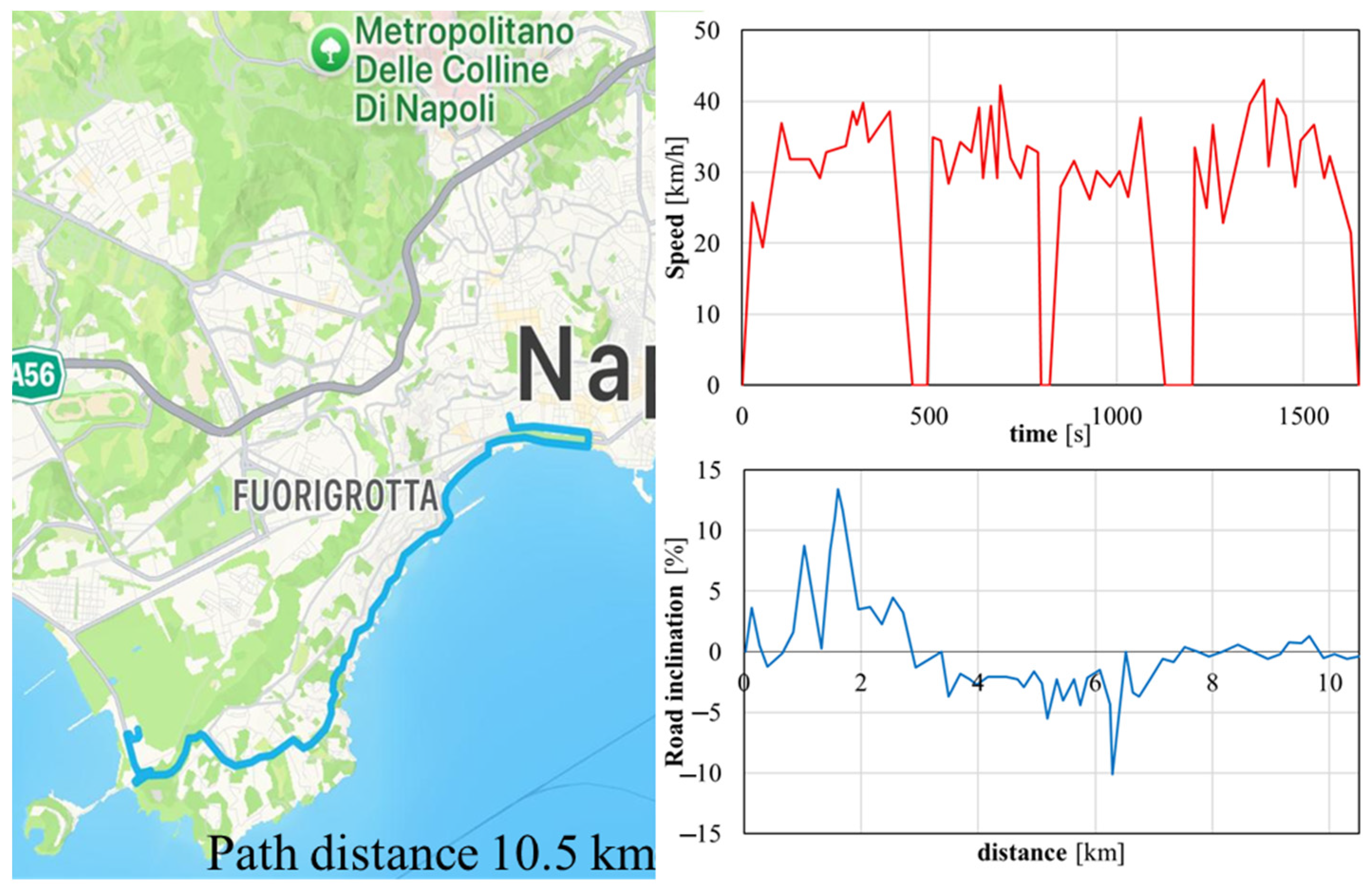
This section reports the results of simulations conducted on the developed electric vehicle model. The simulations were conducted based on the urban route detected and shown in Figure 5, executed in the city of Naples. The detected route, as presented in the previous section, is characterized by a speed profile and an altitude profile, the two input elements required by the model to simulate vehicle dynamics during its operation. The vehicle with which the experimental survey was carried out is the Citroen Ami; based on the surveys conducted, validation of the vehicle dynamics model was performed with respect to the State of Charge (SoC) variable, comparing experimental data with simulated data and quantifying the model’s goodness through evaluation of root mean square error (RMSE). Before showing the results obtained in the validation process, some of the main data of the Citroen Ami are reported. Table 1 reports the main data in terms of arrangement of elements that compose the battery (number of elements in series and parallel), the allowable voltage range on the single element, and the overall capacity of the entire battery.
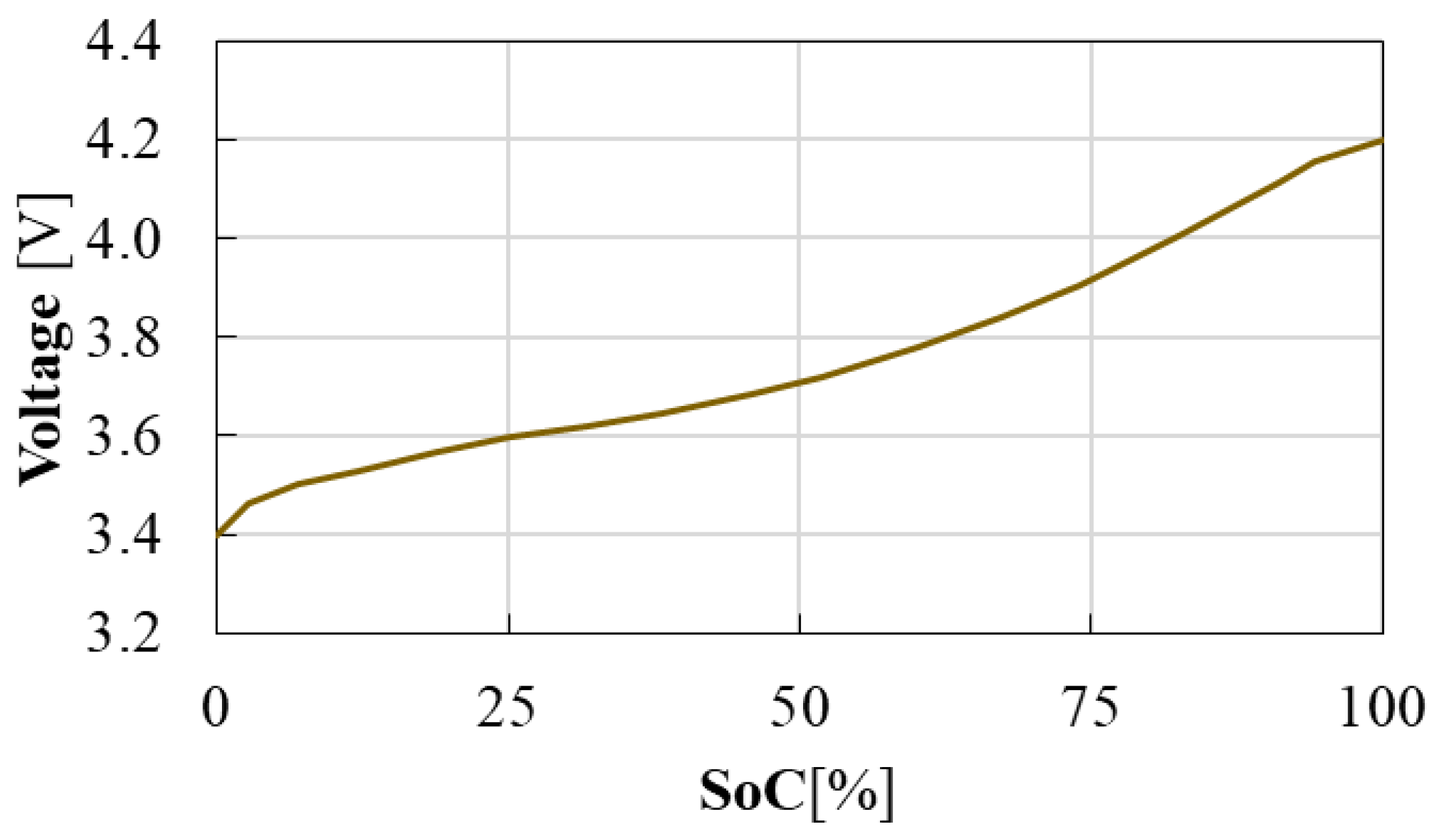
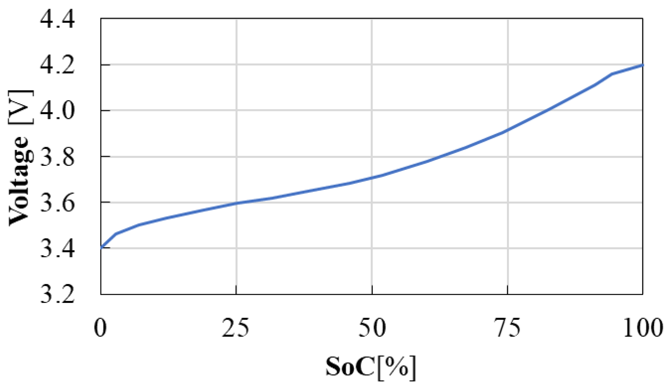
Figure 7 reports the curve defined as OCV, namely open circuit voltage, relative to the single cell that composes the battery.
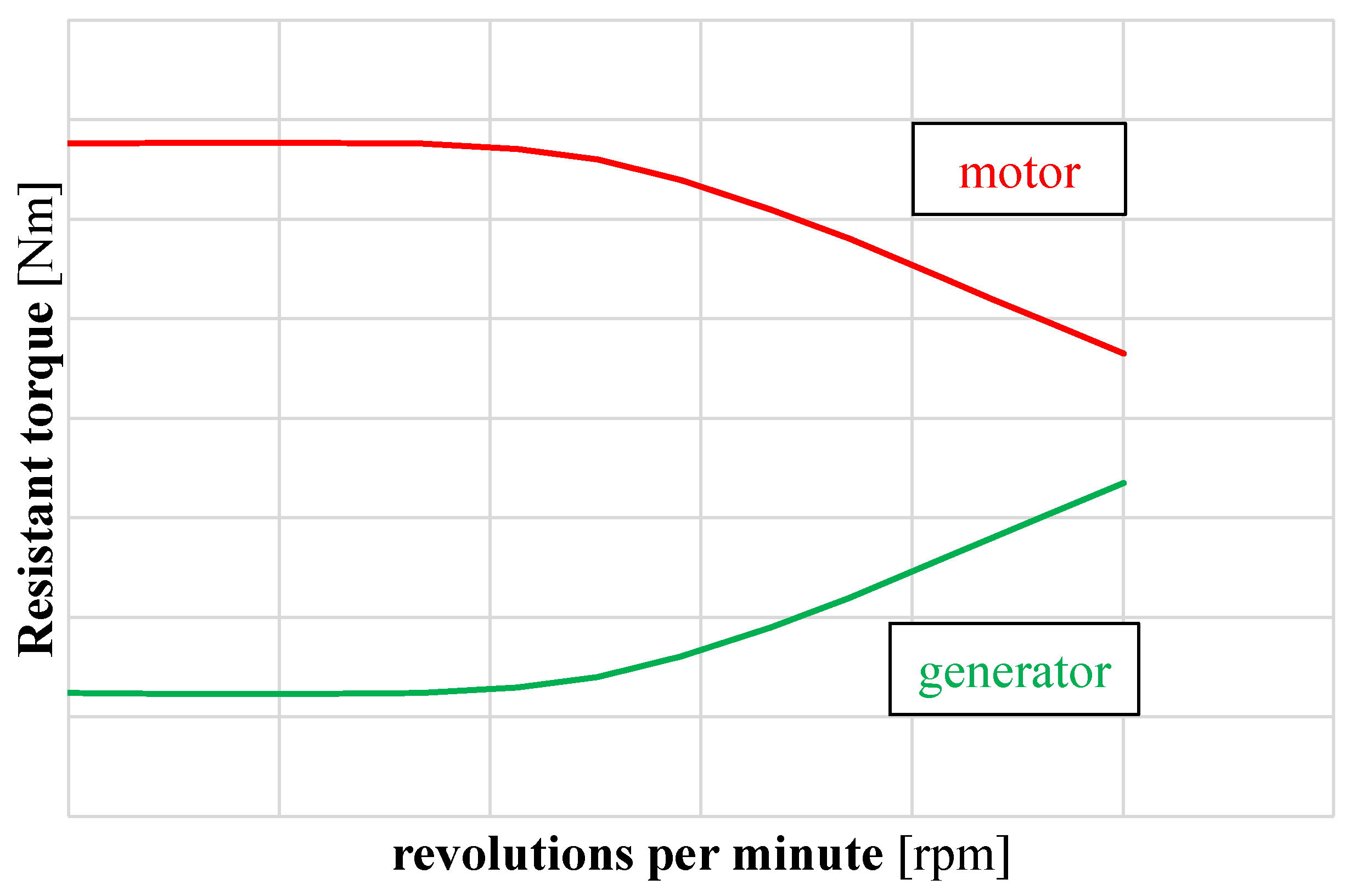
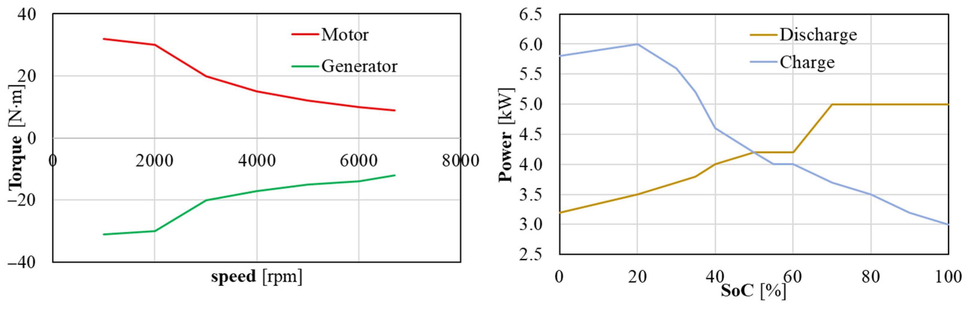
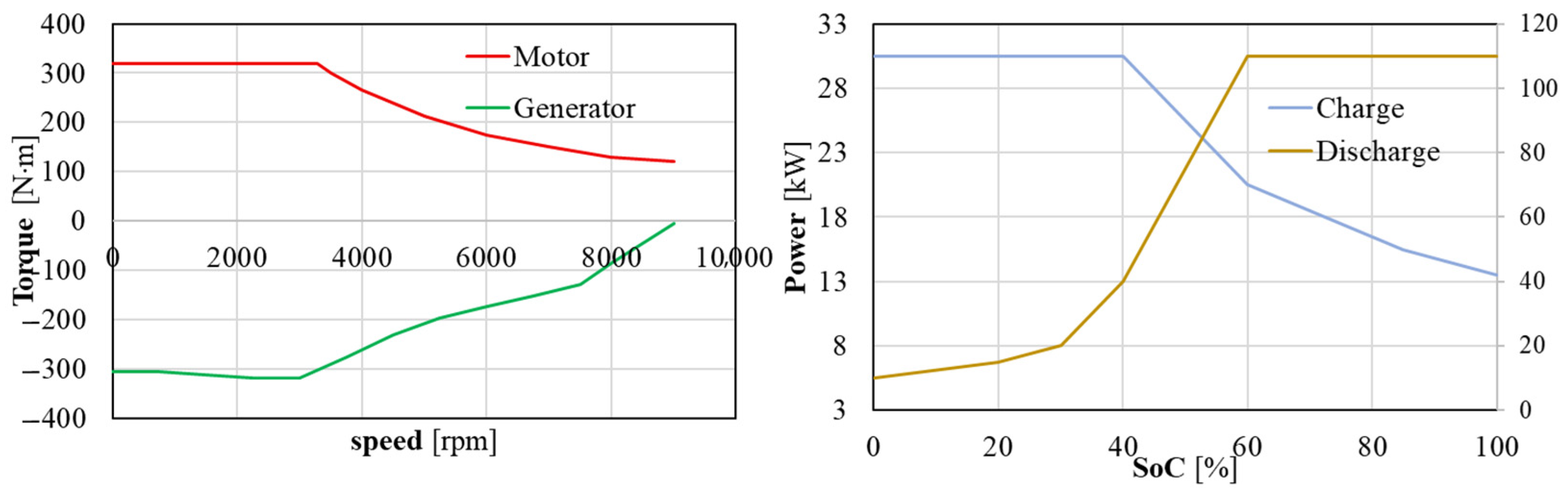
Furthermore, Figure 8 reports two key performance maps characterizing the electric motor and battery system adopted for the Citroën Ami, which served as a reference vehicle in this study. The left-hand plot illustrates the torque versus speed behaviour of the e-motor in both motoring (positive torque) and generating (negative torque) modes. It can be observed that maximum torque is available at low rotational speeds and gradually decreases with increasing speed, consistent with the typical behaviour of small permanent magnet electric motors. The right-hand plot shows the power limits during battery charge and discharge as a function of the state of charge. The discharge power capability increases with SoC until a saturation threshold is reached, while the charging power progressively decreases as the battery approaches full charge. This mapping plays a crucial role in defining the dynamic limits imposed by the battery management system and is integrated into the AVL CRUISETM M simulation to ensure realistic energy flow calculations.
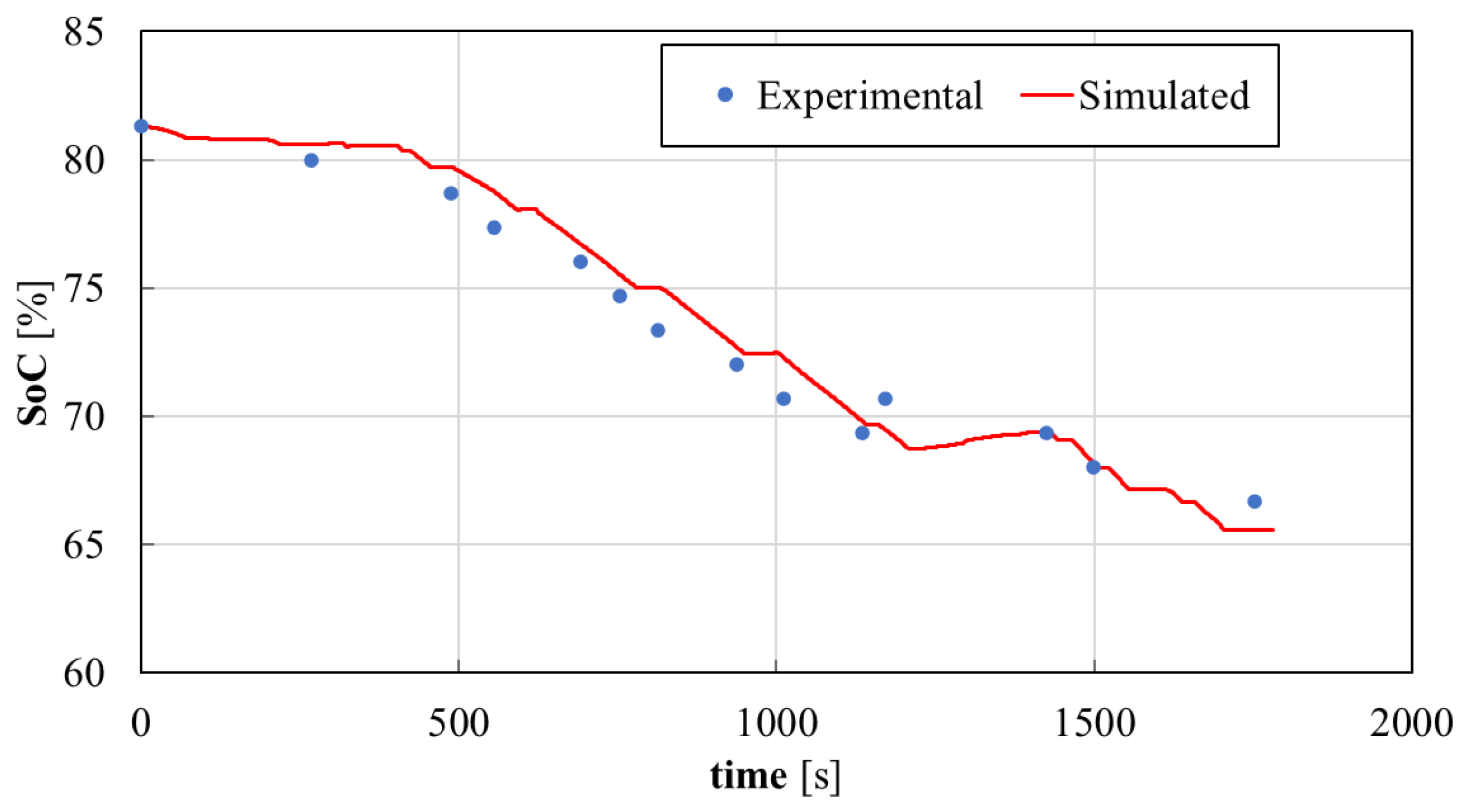
The validation process was conducted by comparing SoC values monitored during the route performed with the Citroen Ami and the values obtained from simulation of the same route on the vehicle dynamics model. Figure 9 reports the graph of the state of charge detected experimentally and that simulated. The comparison between experimental and simulated SoC values highlights excellent adherence of the model to the vehicle’s real behaviour. The root mean square error (RMSE) value of 1.28%, along with the man absolute error (MAE) of 0.82 and the coefficient of determination (R2) equal to 0.97, confirms the good capacity of the model developed in AVL CRUISETM M to reproduce the system’s energy dynamics. The discrepancy observed starting from approximately 1000 s can be attributed not so much to a modelling deficiency but to dynamic vehicle conditions that prevent regeneration activation. In this time interval, in fact, despite the route slope being negative (downhill), the vehicle shows an increasing speed profile and infrequently engages in actual braking, which indicates that the electric motor continues to work in motor mode, absorbing energy from the battery, rather than in regeneration. Additionally, the absence of detailed experimental information on the braking system characteristics has limited the possibility of precisely calibrating the transition logic between regenerative and mechanical braking. The integration of this data represents a natural margin for model improvement.
To further assess the robustness of the model, the same comparison was carried out on the return route along the same road segment. Although this second profile presents a different duration and slightly different dynamics, the simulation results remain consistent with the real measurements. As shown in Figure 10, the RMSE, MAE and R2 values for the return segment were 1.50%, 0.82, and 0.96, respectively. These results confirm the model’s ability to generalize under varying conditions and validate its reliability in replicating energy dynamics even in slightly different scenarios.
The model’s behaviour results are consistent with the system’s physical reality and the residual discrepancies are justified and technically interpretable.
During the model development and validation process, sensitivity analyses were conducted on critical parameters to ensure robust performance across varying operational conditions. Key parameters investigated included brake pedal pressure calibration and regenerative braking percentage tuning, which directly affect the energy recovery efficiency and overall vehicle energy consumption patterns.
The model demonstrated stable behaviour across the range of driving conditions encountered in the experimental validation, including varying speed profiles (0–50 km/h), diverse braking intensities, and road gradient changes (−5% to +3%) present in the urban Naples route. The brake blending logic successfully adapted to different deceleration requirements, while the regenerative braking system responded appropriately to varying road conditions and driver inputs.
While comprehensive sensitivity analysis results are beyond the scope of this foundational modelling work, the consistent accuracy achieved across both outbound and return journeys (RMSE of 1.28% and 1.50% respectively) with different driving dynamics demonstrates the model’s inherent robustness to operational parameter variations. Future work will focus on systematic sensitivity studies across broader parameter ranges to further characterize model behaviour for diverse fleet applications.
The validation conducted on the Citroen AMI, based on a comparison between experimental and simulated data in terms of state of charge (SoC), has confirmed the reliability of integrated logics within the model. This result represents a fundamental step, as it allows for considering the developed model as a reliable tool for analysing further case studies related to other electric vehicles. Therefore, based on this validation, further results referring to another electric vehicle, namely the Nissan Leaf, will be presented. In Figure 11 and Table 2 the main characteristics of a Nissan Leaf’s battery are shown.
Figure 12 presents the performance characteristics of the electric powertrain for the Nissan Leaf, used as a secondary reference for comparison.
On the left, the torque-speed map highlights the broader operating envelope of the Leaf’s electric motor, which delivers a maximum torque of approximately 320 N·m at low rotational speeds, with a gradual decrease beyond 3000 rpm. The regenerative (generator) torque follows a similar profile, reaching a peak of about −300 N·m. This behaviour reflects the vehicle’s higher power class and more robust motor design, capable of sustaining high torque over an extended speed range. The right-hand graph illustrates the charge and discharge power limits of the battery as a function of SoC. Notably, the battery supports significantly higher power rates—up to 30 kW for charging and 120 kW for discharging—compared to the Citroën Ami. These characteristics confirm the Leaf’s suitability for high-performance applications and justify the higher current thresholds included in the simulation constraints. As in the previous case, these maps were integrated into the AVL CRUISE MTM environment to model the energy flow accurately and replicate realistic powertrain behaviour. The developed model, characterized with Nissan Leaf data, was therefore tested on the same driving profile detected with the Citroen Ami in order to find coherence in logic operation based on a known profile.
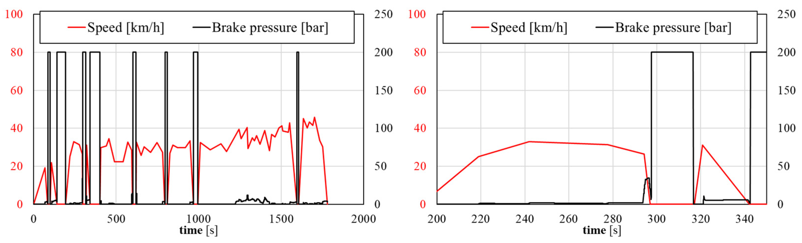
The first pair of graphs shows the trend of pressure exerted by the driver on the brake pedal, reproduced by the “Cockpit” type (which in AVL CRUISE™ M represents the cockpit and characteristics of the brake and accelerator pedals). An ordinary urban route can be characterized by different conditions (e.g., slowdowns due to traffic, traffic lights, etc.); however, from the graphs shown in Figure 13, it is possible to appreciate how as speed decreases, brake action is more or less incisive (in terms of numerical pressure value) and a function of the desired deceleration of the vehicle. In the right panel of Figure 13, it is possible to appreciate how, between 280 s–300 s, as pressure increases, the speed maintained by the vehicle decreases, progressively passing from about 35 km/h until a complete stop around 300 s.
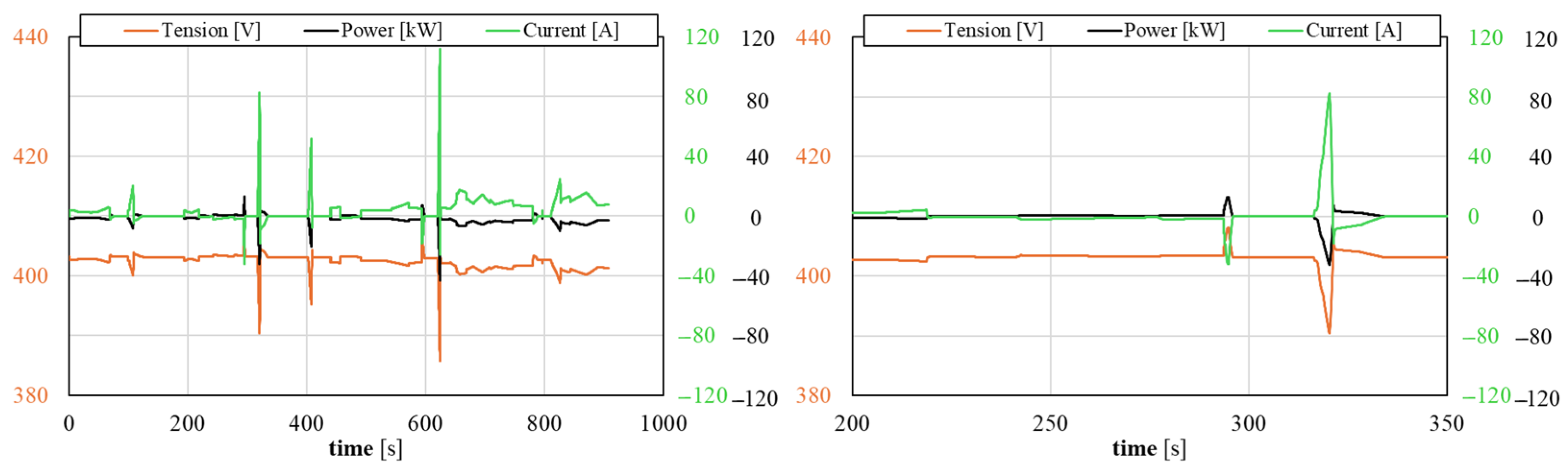
In the two subsequent graphs (Figure 14), voltage, current, and power trends of the onboard battery are proposed. Negative trends are useful for describing the operating logic (they are therefore a convention). In fact, when quantities assume negative values, it means the battery is delivering power, and therefore, the vehicle is operating in traction. In the right panel, it is possible to better appreciate the differences between the power delivery phase by the battery and the accumulation phase during braking, which bes regenerative. In fact, recalling the previously analysed trends, reported in Figure 13, corresponding to brake pedal actuation between 280 s and 300 s, a positive power trend of about 10 kW is recorded. The positive sign, in this case, suggests a power input into the battery due precisely to “regenerative braking.” Conversely, power delivery by the battery for traction purposes involves negative power trends. Around 320 s, this trend is clearly visible, corresponding to increasing speed trends (as reported in Figure 10) as the power is delivered by the battery with values significantly higher (about 20 kW) compared to those of the accumulation phase.
Finally, the SoC trend throughout the entire route (Figure 15), with the relative focus on the same time interval of the previous graphs. The simulation was conducted starting from a state of charge equal to 100%. Consistent with what is shown in the previous graphs, the state of charge trend shows an evident reduction of charge present within the battery with various moments in which this is restored thanks to the modelled regenerative braking integrated in the electric vehicle model. In the right graph, as for the previous ones, it is interesting to note how the state of charge increases during regenerative braking, therefore managed by the onboard electric motor in generator drive, which is interrupted when mechanical braking intervenes, leading to a complete vehicle stop. In this situation, in fact, the state of charge remains constant for the entire duration of the stop (from about 290 s to 315 s), decreasing significantly upon restart (about 320 s).
Based on the results obtained and the consistency observed between the simulated and experimental data, further considerations can be drawn regarding the reliability and potential applicability of the developed digital model. The vehicle dynamics model developed in this work demonstrates a high level of accuracy in reproducing the energy behaviour of the electric powertrain, as confirmed by the strong agreement between the simulated and experimental SoC profiles. The low values of RMSE and MAE, together with a high R2, reflect the model’s ability to reliably capture the essential dynamics of real-world operation, even under varying road slope and braking conditions. While the present study focuses on simulation-based validation, the consistency between simulation and experimental data reinforces the credibility of the model and its suitability as a digital twin for predictive applications. The modular structure and the physical soundness of the modelling framework make it well-suited for future integration into real-time control systems, such as Hardware-in-the-Loop (HiL) platforms or embedded prototypes. To enable full experimental validation of the entire system—including real-time energy management and brake blending logic—additional steps would involve the implementation of real-time interfaces, acquisition of high-frequency sensor data, and actuator feedback. However, thanks to the quality and robustness of the digital model already demonstrated in this work, the transition toward such experimental integration is technically feasible and represents a natural extension of the present study.
While direct comparative validation against a broad spectrum of external models presents inherent challenges due to differing scopes, abstraction levels, and data availability, the significance of our proposed multi-physics EV model lies in its unique combination of high-fidelity representation and comprehensive validation against real-world operational data. This level of detail and empirical grounding, specifically tailored for integration within a digital twin framework, provides a precision for dynamic V2G energy management that simpler, generalized models often cannot achieve. The model’s verified accuracy under diverse driving conditions highlights its reliability as a foundational tool for developing intelligent, AI-driven V2G solutions.

5. Conclusions

This research presents a comprehensive framework for digital twin-enabled Vehicle-to-Grid systems through the development and validation of a high-fidelity multi-physics electric vehicle model that serves as a fundamental building block for AI-driven energy management applications in novel power systems.
The developed multi-physics electric vehicle model demonstrates exceptional accuracy with an RMSE between 1.28% (outbound path) and 1.50% (return path) for state of charge prediction, validated through experimental data from real-world urban driving conditions in Naples, Italy. This precision provides the data quality necessary for training machine learning algorithms that can optimize V2G operations in real-time. The model’s transferability across different vehicle platforms (Citroën Ami and Nissan Leaf) establishes its versatility for fleet-scale AI implementations.
The validated digital twin framework addresses critical challenges in applying artificial intelligence to novel power systems by providing high-fidelity training data for machine learning algorithms, real-time simulation capabilities for testing AI optimization strategies, and scalable architecture supporting both individual vehicle and fleet-level AI applications.

AI Algorithm Implementation Example

To demonstrate the model’s AI integration capabilities, consider a reinforcement learning algorithm for optimal charging scheduling. The digital twin model serves as the environment where an AI agent learns to optimize charging decisions based on real-time grid conditions, electricity pricing, and user mobility patterns. The agent receives state information including current SoC, grid load, energy prices, and predicted trip requirements from the validated multi-physics model. Through trial-and-error learning, the AI algorithm discovers optimal policies that minimize charging costs while ensuring vehicle availability. The 1.28% RMSE accuracy ensures the AI agent learns from reliable state representations, leading to robust charging strategies that can be deployed in real-world V2G systems. The validated model provides the necessary simulation fidelity for the AI algorithm to generalize effectively from training to actual deployment scenarios.
This work significantly advances artificial intelligence applications in power systems by establishing the foundational modelling infrastructure required for intelligent V2G implementations. The validated model enables AI algorithms to optimize complex multi-objective problems including energy demand forecasting, intelligent charging scheduling, and automated grid balancing strategies. This research demonstrates how digital twin technology serves as a critical enabler of AI applications in decentralized energy systems, where electric vehicles function as distributed energy storage resources supporting grid resilience through AI-coordinated participation in ancillary services.
Future research directions include implementing deep reinforcement learning algorithms for V2G optimization using the validated model as the training environment, developing federated learning approaches for privacy-preserving AI coordination across distributed vehicle fleets, and scaling the digital twin framework to accommodate large EV fleets with distributed AI processing capabilities. Advanced applications encompass integrating weather forecasting and renewable energy prediction models for enhanced AI-driven energy management and developing explainable AI frameworks for transparent V2G decision-making processes.
This research contributes significantly to the evolution of intelligent power systems by providing validated tools for AI-driven optimization of EV-grid interactions. The demonstrated capability to accurately predict vehicle energy consumption enables more efficient AI-coordinated utilization of renewable energy resources while reducing the environmental impact of transportation systems. The successful integration of digital twin technology with AI-based optimization algorithms represents a significant advancement in smart grid systems, providing a robust foundation for widespread deployment of intelligent V2G systems that leverage artificial intelligence for optimal performance and reliability.
Future work will extend our validated multi-physics EV model for V2G systems by focusing on optimizing computational efficiency for large-scale fleet deployment and real-time operations. Privacy issues will be considered, although not directly by the authors. We will also explore applications to advanced grid services, so to develop robust frameworks for seamless integration with smart grid infrastructure and energy markets and enhance the model’s adaptability for diverse EV configurations and grid conditions.

Author Contributions

Conceptualization, M.C.; methodology, M.C.; software, G.D.P.; validation, G.D.P.; formal analysis, M.C. and G.D.P.; investigation, G.D.P.; resources, M.C.; data curation, G.D.P.; writing—original draft preparation, M.C.; writing—review and editing, M.C.; visualization, G.D.P.; supervision, M.C.; project administration, M.C.; funding acquisition, M.C. All authors have read and agreed to the published version of the manuscript.

Funding

Activities described within the paper are self-funded.

Institutional Review Board Statement

Not applicable.

Informed Consent Statement

Not applicable.

Data Availability Statement

The data presented in this study are available on request from the corresponding author. The data are not publicly available due to privacy restrictions.

Conflicts of Interest

Author Michela Costa was employed by the company DG Twin S.r.l. The remaining authors declare that the research was conducted in the absence of any commercial or financial relationships that could be construed as a potential conflict of interest.

Abbreviations

The following abbreviations are used in this manuscript:
AIArtificial Intelligence
BESSBattery Energy Storage Systems
DEMDigital Elevation Model
DSRCDedicated Short-Range Communications
ECMEquivalent Circuit Model
EVElectric Vehicle
G2VGrid-to-Vehicle
GPSGlobal Positioning System
HiLHardware-in-Loop
OCVOpen Circuit Voltage
PIProportional-Integral
RCResistor-Capacitor
RMSERoot Mean Square Error
SiLSafety Integrity Loop
SoCState of Charge
V2GVehicle-to-Grid
V2XVehicle-to-Everything
WiFiWireless Fidelity

References

  1. Yang, D.; Lv, Y.; Ji, M.; Zhao, F. Evaluation and economic analysis of battery energy storage in smart grids with wind–photovoltaic. Int. J. Low-Carbon Technol. 2024, 19, 18–23. [Google Scholar] [CrossRef]
  2. Dall-Orsoletta, A.; Ferreira, P.; Dranka, G.G. Low-carbon technologies and just energy transition: Prospects for electric vehicles. Energy Convers. Manag. X 2022, 16, 100271. [Google Scholar] [CrossRef]
  3. Tan, K.M.; Ramachandaramurthy, V.K.; Yong, J.Y. Integration of electric vehicles in smart grid: A review on vehicle to grid technologies and optimization techniques. Renew. Sustain. Energy Rev. 2016, 53, 720–732. [Google Scholar] [CrossRef]
  4. İnci, M.; Savrun, M.M.; Çelik, Ö. Integrating electric vehicles as virtual power plants: A comprehensive review on vehicle-to-grid (V2G) concepts, interface topologies, marketing and future prospects. J. Energy Storage 2022, 55, 105579. [Google Scholar] [CrossRef]
  5. Sultan, V.; Aryal, A.; Chang, H.; Kral, J. Integration of EVs into the smart grid: A systematic literature review. Energy Inform. 2022, 5, 65. [Google Scholar] [CrossRef]
  6. Liu, M.; Fang, S.; Dong, H.; Xu, C. Review of digital twin about concepts, technologies, and industrial applications. J. Manuf. Syst. 2021, 58, 346–361. [Google Scholar] [CrossRef]
  7. PLATOON H2020 EU Project. Digital Platform and Analytics Technologies for Optimized Operations Along the Energy Value Chain. Available online: https://platoon-project.eu/ (accessed on 5 June 2025).
  8. Costa, M.; Coppola, A.; Marra, F.S.; Piazzullo, D. Simulated Database and AI Modelling Support for the Development of Biomass-Based Hybrid micro Power Grids. In Proceedings of the Symposium SUM 2025, Naples, Italy, 21–23 May 2025. [Google Scholar]
  9. Mchirgui, N.; Quadar, N.; Kraiem, H.; Lakhssassi, A. The applications and challenges of digital twin technology in smart grids: A comprehensive review. Appl. Sci. 2024, 14, 10933. [Google Scholar] [CrossRef]
  10. Ali, W.A.; Fanti, M.P.; Roccotelli, M.; Ranieri, L. A review of digital twin technology for electric and autonomous vehicles. Appl. Sci. 2023, 13, 5871. [Google Scholar] [CrossRef]
  11. Grieves, M.W. Digital twins: Past, present, and future. In The Digital Twin 2023; Springer International Publishing: Cham, Switzerland, 2023; pp. 97–121. [Google Scholar]
  12. Ahmad, T.; Zhang, H.; Yan, B. A review on renewable energy and electricity requirement forecasting models for smart grid and buildings. Sustain. Cities Soc. 2020, 55, 102052. [Google Scholar] [CrossRef]
  13. Hashmi, S.A.; Ali, C.F.; Zafar, S. Internet of things and cloud computing-based energy management system for demand side management in smart grid. Int. J. Energy Res. 2021, 45, 1007–1022. [Google Scholar] [CrossRef]
  14. Shaukat, N.; Khan, B.; Ali, S.; Mehmood, C.; Khan, J.; Farid, U.; Majid, M.; Anwar, S.; Jawad, M.; Ullah, Z. A survey on electric vehicle transportation within smart grid system. Renew. Sustain. Energy Rev. 2018, 81, 1329–1349. [Google Scholar] [CrossRef]
  15. Sevdari, K.; Calearo, L.; Andersen, P.B.; Marinelli, M. Ancillary services and electric vehicles: An overview from charging clusters and chargers technology perspectives. Renew. Sustain. Energy Rev. 2022, 167, 112666. [Google Scholar] [CrossRef]
  16. Barman, P.; Dutta, L.; Bordoloi, S.; Kalita, A.; Buragohain, P.; Bharali, S.; Azzopardi, B. Renewable energy integration with electric vehicle technology: A review of the existing smart charging approaches. Renew. Sustain. Energy Rev. 2023, 183, 113518. [Google Scholar] [CrossRef]
  17. Deng, R.; Xiang, Y.; Huo, D.; Liu, Y.; Huang, Y.; Huang, C.; Liu, J. Exploring flexibility of electric vehicle aggregators as energy reserve. Electr. Power Syst. Res. 2020, 184, 106305. [Google Scholar] [CrossRef]
  18. Hota, A.R.; Juvvanapudi, M.; Bajpai, P. Issues and solution approaches in PHEV integration to smart grid. Renew. Sustain. Energy Rev. 2014, 30, 217–229. [Google Scholar] [CrossRef]
  19. Liu, L.S.; Kong, F.X.; Liu, X.; Peng, Y.; Wang, Q.L. A review on electric vehicles interacting with renewable energy in smart grid. Renew. Sustain. Energy Rev. 2015, 51, 648–661. [Google Scholar] [CrossRef]
  20. Assad, U.; Hassan, M.A.S.; Farooq, U.; Kabir, A.; Khan, M.Z.; Bukhari, S.S.H.; Jaffri, Z.u.A.; Oláh, J.; Popp, J. Smart Grid, Demand Response and Optimization: A Critical Review of Computational Methods. Energies 2022, 15, 2003. [Google Scholar] [CrossRef]
  21. Luo, X.; Shi, W.; Jiang, Y.; Liu, Y.; Xia, J. Distributed peer-to-peer energy trading based on game theory in a community microgrid considering ownership complexity of distributed energy resources. J. Clean. Prod. 2022, 351, 131573. [Google Scholar] [CrossRef]
  22. Wazirali, R.; Yaghoubi, E.; Abujazar, M.S.; Ahmad, R.; Vakili, A.H. State-of-the-art review on energy and load forecasting in microgrids using artificial neural networks, machine learning, and deep learning techniques. Electr. Power Syst. Res. 2023, 225, 109792. [Google Scholar] [CrossRef]
  23. Bhatti, G.; Mohan, H.; Singh, R.R. Towards the future of smart electric vehicles: Digital twin technology. Renew. Sustain. Energy Rev. 2021, 141, 110801. [Google Scholar] [CrossRef]
  24. Mojumder, M.R.H.; Ahmed Antara, F.; Hasanuzzaman, M.; Alamri, B.; Alsharef, M. Electric vehicle-to-grid (V2G) technologies: Impact on the power grid and battery. Sustainability 2022, 14, 13856. [Google Scholar] [CrossRef]
  25. Mwasilu, F.; Justo, J.J.; Kim, E.K.; Do, T.D.; Jung, J.W. Electric vehicles and smart grid interaction: A review on vehicle to grid and renewable energy sources integration. Renew. Sustain. Energy Rev. 2014, 34, 501–516. [Google Scholar] [CrossRef]
  26. Xiang, Y.; Hu, S.; Liu, Y.; Zhang, X.; Liu, J. Electric vehicles in smart grid: A survey on charging load modelling. IET Smart Grid 2019, 2, 25–33. [Google Scholar] [CrossRef]
  27. Rathor, S.K.; Saxena, D. Energy management system for smart grid: An overview and key issues. Int. J. Energy Res. 2020, 44, 4067–4109. [Google Scholar] [CrossRef]
  28. Fu, J.; Li, H.; Sun, X.; He, T.; Zhang, G.; Wei, C. Multi-physics simulation modelling and energy flow characterization of thermal management system for a sport utility vehicle under high-temperature conditions. Energy 2025, 316, 134653. [Google Scholar] [CrossRef]
  29. Beatrice, C.; Capasso, C.; Costa, M.; Di Blasio, G.; Di Luca, G.; Iantorno, F.; Martoriello, G. Model based optimal management of a hybrid propulsion system for leisure boats. J. Energy Storage 2022, 46, 103896. [Google Scholar] [CrossRef]
  30. Escoto, M.; Guerrero, A.; Ghorbani, E.; Juan, A.A. Optimization challenges in vehicle-to-grid (V2G) systems and artificial intelligence solving methods. Appl. Sci. 2024, 14, 5211. [Google Scholar] [CrossRef]
  31. Khaleghian, S. AI-Driven Smart Cities: Digital Twin Simulation, V2X Communication, and EV Infrastructure Optimization. Available online: https://scholar.utc.edu/cgi/viewcontent.cgi?article=2178&context=theses (accessed on 31 May 2025).
  32. Yang, Z.; Li, K.; Foley, A. Computational scheduling methods for integrating plug-in electric vehicles with power systems: A review. Renew. Sustain. Energy Rev. 2015, 51, 396–416. [Google Scholar] [CrossRef]
  33. Kumar, S.; Dwivedi, S.; Singh, R. Impact of Artificial Intelligence on the Planning and Operation of Distributed Energy Systems in Smart Grids. Energies 2024, 17, 4501. [Google Scholar] [CrossRef]
  34. Srihari, G.; Krishnam Naidu, R.S.R.; Falkowski-Gilski, P.; Bidare Divakarachari, P.; Kiran Varma Penmatsa, R. Integration of electric vehicle into smart grid: A meta heuristic algorithm for energy management between V2G and G2V. Front. Energy Res. 2024, 12, 1357863. [Google Scholar] [CrossRef]
  35. Kumar, A.; Singh, P.; Sharma, R. Optimizing demand response and load balancing in smart EV charging networks using AI integrated blockchain framework. Sci. Rep. 2024, 14, 82257. [Google Scholar] [CrossRef] [PubMed]
  36. Arrano-Vargas, F.; Konstantinou, G. Digital Twins for the Future Power System: An Overview and a Future Perspective. Sustainability 2023, 15, 5259. [Google Scholar] [CrossRef]
  37. Zhang, Y.; Wang, L.; Chen, M. Transforming the electrical grid: The role of AI in advancing smart, sustainable, and secure energy systems. Energy Inform. 2024, 7, 461. [Google Scholar]
  38. Cheng, L.; Huang, P.; Zhang, M.; Yang, R.; Wang, Y. Optimizing Electricity Markets Through Game-Theoretical Methods: Strategic and Policy Implications for Power Purchasing and Generation Enterprises. Mathematics 2025, 13, 373. [Google Scholar] [CrossRef]
  39. Sharmila, B.; Srinivasan, K.; Devasena, D.; Suresh, M.; Panchal, H.; Ashokkumar, R.; Meenakumari, R.; Sadasivuni, K.K.; Shah, R.R. Modelling and performance analysis of electric vehicle. Int. J. Ambient. Energy 2022, 43, 5034–5040. [Google Scholar] [CrossRef]
  40. Yu, Q.; Li, J.; Feng, D.; Liu, X.; Yuan, J.; Zhang, H.; Wang, X. Modeling electric vehicle behavior: Insights from long-term charging and energy consumption patterns through empirical trajectory data. Appl. Energy. 2025, 380, 125066. [Google Scholar] [CrossRef]
  41. Adegbohun, F.; von Jouanne, A.; Phillips, B.; Agamloh, E.; Yokochi, A. High Performance Electric Vehicle Powertrain Modeling, Simulation and Validation. Energies 2021, 14, 1493. [Google Scholar] [CrossRef]
  42. de Carvalho Pinheiro, H. PerfECT Design Tool: Electric Vehicle Modelling and Experimental Validation. World Electr. Veh. J. 2023, 14, 337. [Google Scholar] [CrossRef]
Figure 1. Vehicle model developed with details of its main components, whether related to the physical architecture of the artifact, functional (e.g., Cycle Run), or useful for result visualization.
Applsci 15 08214 g001
Figure 2. Representative curves of torque on the electric motor in motor operation (red) and generator (green).
Applsci 15 08214 g002
Figure 3. Overall system and logical architecture of the e-vehicle model.
Applsci 15 08214 g003
Figure 4. Flow chart of control logics integrated in the vehicle dynamics model for energy flow management.
Applsci 15 08214 g004
Figure 5. Map of the city of Naples with the GPS route detected during the driving test and the detected profiles: speed in the upper right and road inclination in the lower right (outbound path).
Applsci 15 08214 g005
Figure 6. Map of the city of Naples with the GPS route with speed profile in the upper right and road inclination in the lower right (return path).
Applsci 15 08214 g006
Figure 7. Open circuit voltage (OCV) curve of the cell that composes the battery installed on the Citroen Ami.
Applsci 15 08214 g007
Figure 8. Left: Motor/generator torque vs. speed map for the Citroën Ami. Right: Battery charge/discharge power as a function of the state of charge (SoC).
Applsci 15 08214 g008
Figure 9. Validation of the electric vehicle simulation model: comparison of SoC detected in the field (blue points) on the Citroen Ami and simulated profile (red curve)—outbound path.
Applsci 15 08214 g009
Figure 10. Comparison of the experimental state (blue point) of charge of the return path and the simulated scenario (red line).
Applsci 15 08214 g010
Figure 11. Open circuit voltage (OCV) curve of the cell that composes the battery installed on the Nissan Leaf.
Applsci 15 08214 g011
Figure 12. (Left): Motor/generator torque vs speed map for the Nissan Leaf. (Right): Battery charge/discharge power limits versus SoC.
Applsci 15 08214 g012
Figure 13. Simulated trend of pressure exerted on the vehicle brake (black) as a function of the detected speed profile (red).
Applsci 15 08214 g013
Figure 14. Trend of voltage, current couple and power exchanged on the Nissan Leaf electric vehicle battery.
Applsci 15 08214 g014
Figure 15. Nissan Leaf battery state of charge trend on the simulated route.
Applsci 15 08214 g015
Table 1. Citroen Ami battery characteristics.
ElementsNserie12[-]
Nparallel1
VoltageMin3.4[V]
Max4.2
Capacity-120[Ah]
Table 2. Nissan Leaf battery characteristics.
ElementsNserie96[-]
Nparallel2
VoltageMin3.4[V]
Max4.2
Capacity-50[Ah]
Disclaimer/Publisher’s Note: The statements, opinions and data contained in all publications are solely those of the individual author(s) and contributor(s) and not of MDPI and/or the editor(s). MDPI and/or the editor(s) disclaim responsibility for any injury to people or property resulting from any ideas, methods, instructions or products referred to in the content.

