You are currently viewing a new version of our website. To view the old version click .
Applied Sciences
  • Article
  • Open Access

22 July 2025

Friction Stir Welding Process Using a Manual Tool on Polylactic Acid Structures Manufactured by Additive Techniques

,
,
,
and
1
Teaching and Research Laboratories of the Central Research Support Services (SCAI), University of Jaen, A2 Building—Campus Las Lagunillas, s/n, 23071 Jaen, Spain
2
Department of Manufacturing Engineering, Industrial Engineering School, Universidad Nacional de Educación a Distancia (UNED), St/Juan del Rosal 12, 28040 Madrid, Spain
3
Department of Mechanical and Mining Engineering, University of Jaen, A3 Building—Campus Las Lagunillas, s/n, 23071 Jaen, Spain
*
Author to whom correspondence should be addressed.
This article belongs to the Special Issue Recent Advances in Manufacturing and Machining Processes

Abstract

This study analyses the application of the Friction Stir Welding (FSW) process on polymeric materials manufactured by additive manufacturing (AM), specifically with polylactic acid (PLA). FSW is a solid-state welding process characterized by its low heat input and minimal distortion, which makes it ideal for the assembly of complex or large components made by additive manufacturing. To evaluate its effectiveness, a portable FSW device was developed for the purpose of joining PLA specimens made by AM using different filler densities (15% and 100%). Two tool geometries (a cylindrical and truncated cone) were utilized by varying the parameters of rotational speed, tilt angle, and feed rate. The results revealed two different process stages, transient and steady-state, and showed differences in weld quality depending on the material density, tool type, and material addition. The study confirms the viability of FSW for joining PLA parts made by AM and suggests potential applications in industries that require robust and precise joints in plastic parts, thereby helping hybrid manufacturing to progress.

1. Introduction

The development of effective methods for joining metal components has played a key role in enabling industrial manufacturing and production. Despite significant advancements in the knowledge and development of new materials, the need for joining techniques remains crucial for the fabrication, repair, and maintenance of machinery, tools, and structures [1,2,3]. Although new joining techniques have emerged alongside novel materials, the general classification of joining methods has remained relatively unchanged. These methods fall into two primary categories: non-permanent joints, such as mechanical fasteners (screws, rivets, and bolts), and permanent joints, including adhesive bonding and welding [4,5,6].
Welding is a fundamental process used to permanently join two or more solid components. Welding processes can be categorized into soft and hard soldering (where only filler material melts), fusion welding (where the base metal melts, often with filler material), and solid-state welding (where no melting occurs) [4,7]. Friction Stir Welding (FSW) belongs to the solid-state category and was developed by The Welding Institute (TWI) in the UK in 1991 [4,5,7]. Initially created for joining aluminum alloys, FSW has gained significant industrial popularity, especially for welding composite and polymeric materials [8,9,10,11,12]. Today, FSW is widely used in aerospace, marine, automotive, and railway industries, and more recently, in parts manufactured by additive manufacturing (AM) [13]. FSW can be implemented using a range of equipment, from modified CNC milling machines to purpose-built FSW platforms and robotic arms. The process can be implemented in manual, semi-automatic, and fully automatic modes [9,11], depending on the production requirements. The manual method is cost-effective, straightforward, and offers flexibility, making it well suited for research and prototyping. However, it falls short in terms of the precision, repeatability, and scalability needed for industrial applications. Automated systems, on the other hand, provide better accuracy, process control, and consistent quality, which are essential for mass production, though they tend to be more expensive and less adaptable to quick changes during experimentation [14]. To carry out this project, a novel manual and portable friction welding device, with and without filler material, was designed and patented, as described in detail in the Section 2.
Additive manufacturing (AM) has grown rapidly in recent years, partly due to the expiration of key related patents. AM involves creating three-dimensional objects by adding the material layer by layer [15,16,17,18]. This process allows for design flexibility, customization, and the production of complex geometries that are difficult or impossible to achieve with traditional methods. AM has applications across various industries, including the automotive, aerospace, medical, and fashion sectors. Welding plays a significant role in the context of AM, particularly for post-processing, repairs, and part assembly. For instance, welding allows for the joining of large parts that exceed the build volume of AM machines [19], the combination of different materials manufactured separately, or the repair of damaged or defective sections without remanufacturing the entire part. These capabilities expand the practical applicability of AM and make solid-state welding techniques like Friction Stir Welding (FSW) especially attractive due to their low heat input and ability to produce high-integrity joints with minimal distortion, when the appropriate tool is chosen [20,21]. Additively manufactured (AM) components typically exhibit a high degree of anisotropy due to the layer-by-layer deposition of the material, particularly in filament-based processes [22], even with 100% infill density [22]. Other AM techniques, such as those using powder beds, also present a certain level of anisotropy [23]. When Friction Stir Welding (FSW) is applied to join AM components, the degree of anisotropy is often significantly reduced as a result of the intense material stirring and plastic deformation that promotes microstructural homogenization across the weld zone [24,25].
The literature analysis shows that many works have focused on welding components manufactured by AM using different plastics, evaluating the mechanical response of the welded parts. Petousis et al. [26] investigated the optimum welding parameters to join PMMA-welded and extruded specimens, producing favorable results in terms of mechanical properties. Similarly, Afshari et al. optimized the FSW parameters for 3D-printed polypropylene/graphene (PP/GNP) nanocomposites. Some studies have focused on the weldability of ABS-printed parts [27,28]. Tiwary et al. performed an optimization in the joint between ABS and PETG [19] without material addition. For PLA, some studies have been performed without material addition [29].
Therefore, studying FSW on AM components is crucial for advancing hybrid manufacturing techniques and ensuring the structural reliability of critical components [30,31,32].
The goal of this study is to analyze the prototype’s functionality on AM-manufactured components in PLA (polylactic acid), the quality of the welds, the process parameters, and the device’s performance. To address these gaps, the current work aims to apply and characterize the Friction Stir Welding (FSW) process on polymeric materials, specifically PLA, produced through additive manufacturing [13,31,33,34,35,36]. Test specimens with varying characteristics were fabricated and joined using FSW. Visual inspections were conducted to assess the feasibility of welds, as the use of different colors in the base parts allows them to be evaluated easily. Additionally, this work optimized the process parameters to achieve high-quality welds in polymeric materials. This research contributes to the broader field of advanced manufacturing by combining two innovative technologies—Friction Stir Welding and additive manufacturing—and exploring their synergistic potential. The outcomes are particularly relevant for industries seeking efficient, high-quality joining solutions for polymer-based components.

2. Materials and Methods

The novel FSW device, designed to join components produced by AM technologies, has been patented (ES2952553 Portable Welding Device) [37]. The equipment consists of two main components: the manual tool, which is held by the operator during the process, and the control box, where the operator can adjust the welding parameters, such as the head rotation speed and the feed rate of the filler material.
Then, the portable, custom-designed hand-operated Friction Stir Welding (FSW) device shown in Figure 1a,b was used to carry out the welding tests [37]. To enhance process control and ensure reproducibility, the device was mounted on a custom-designed vertical milling machine with Cartesian axes (Figure 2). It allowed the fixation of process parameters such as the tool’s vertical position, tilt angle, and welding speed, in order to study the influence of these parameters on the Friction Stir Welding process of thermoplastic material. Other parameters, such as the feeding and rotational speeds, were controlled by the FWS device controller.
Figure 1. (a) Friction Stir Welding equipment; (b) portable package.
Figure 2. (a) The Friction Stir Welding device mounted on a Cartesian vertical milling machine; (b) the details of the fixation.
The material used in the experimental analysis was polylactic acid (PLA), a biodegradable thermoplastic polymer, obtained from the supplier SmartMaterials3D (Alcalá la Real, Spain) [38]. The PLA filaments, with a diameter of 1.75 mm, were used in different colors (white, black, pink, and blue) to make visual inspection easier during the welding process. The variants exhibited highly similar mechanical and thermal properties. PLA’s glass transition temperature is 60 °C [30].
To evaluate the welded joints, a Ninyoon 4K WiFi microscope (Ninyoon, Shenzhen, China) was used, offering magnification from 50× to 1000×. This microscope was used to observe the most relevant areas of the weld joint, which, when combined with the weighing of the specimens, provided information about the amount of material added or lost during the welding process. For weighing, a Gram Lite FS scale (GRAM PRECISION S.L., Barcelona, Spain) with a resolution of 0.1 mg was used.

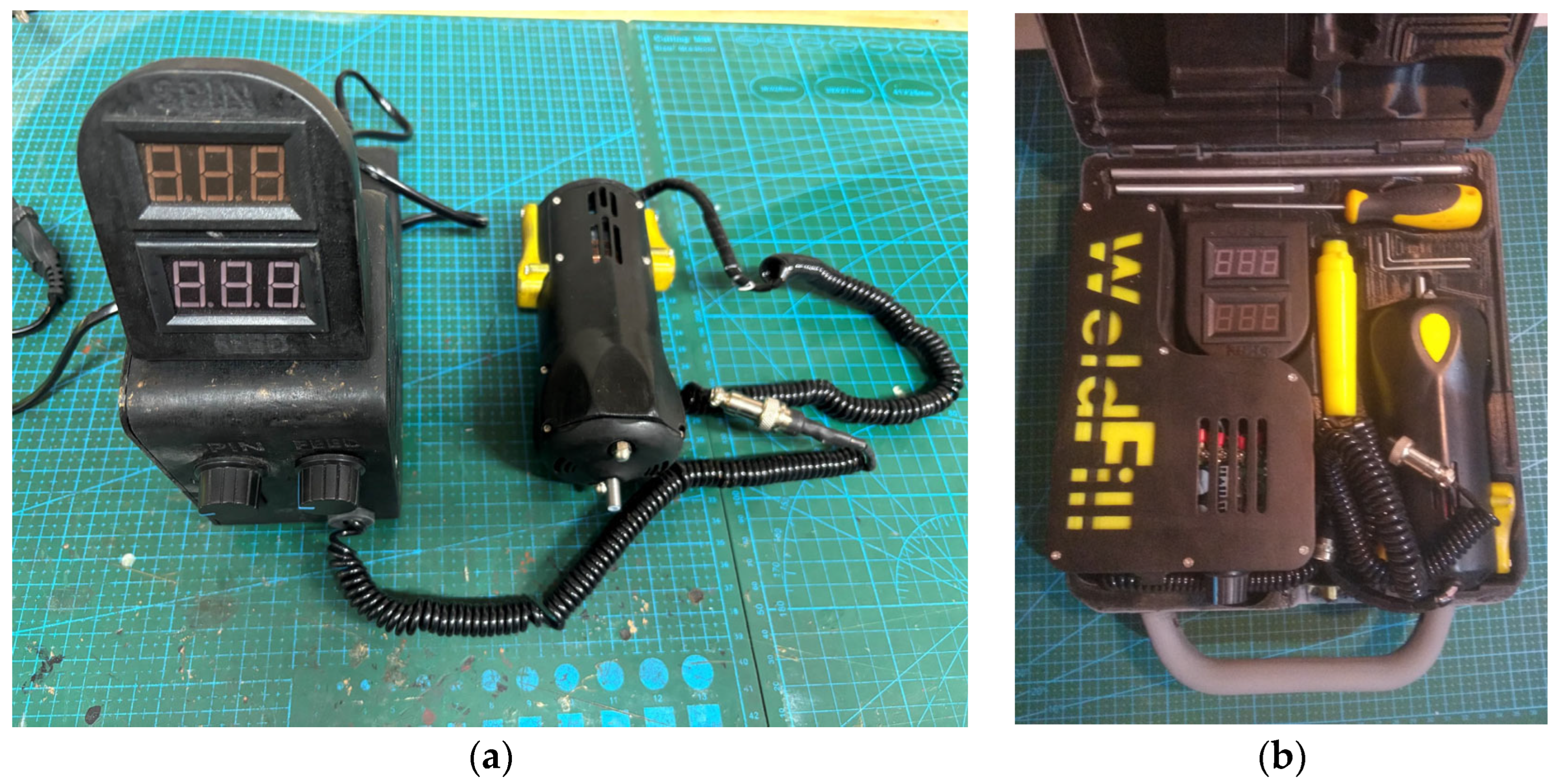
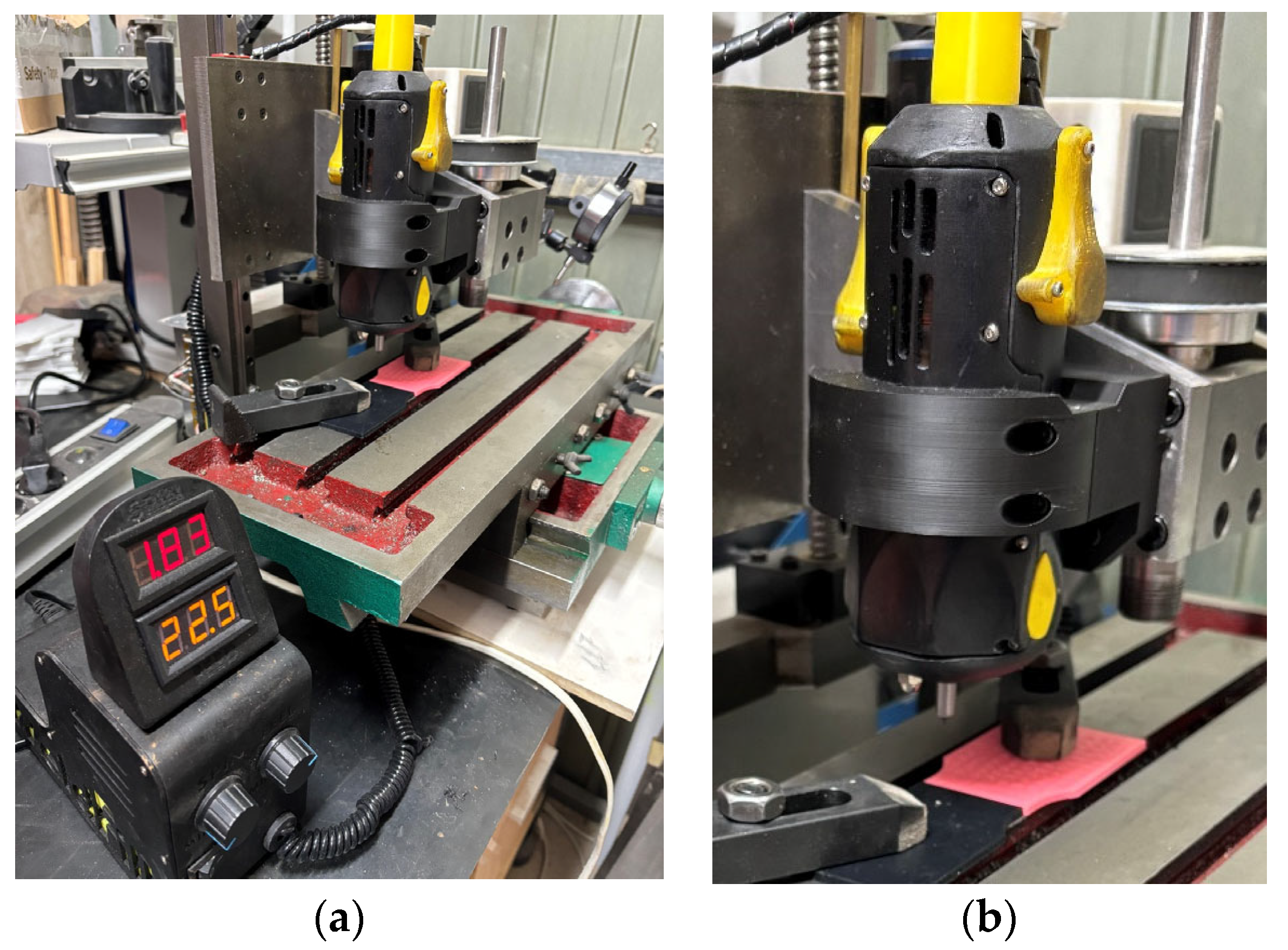
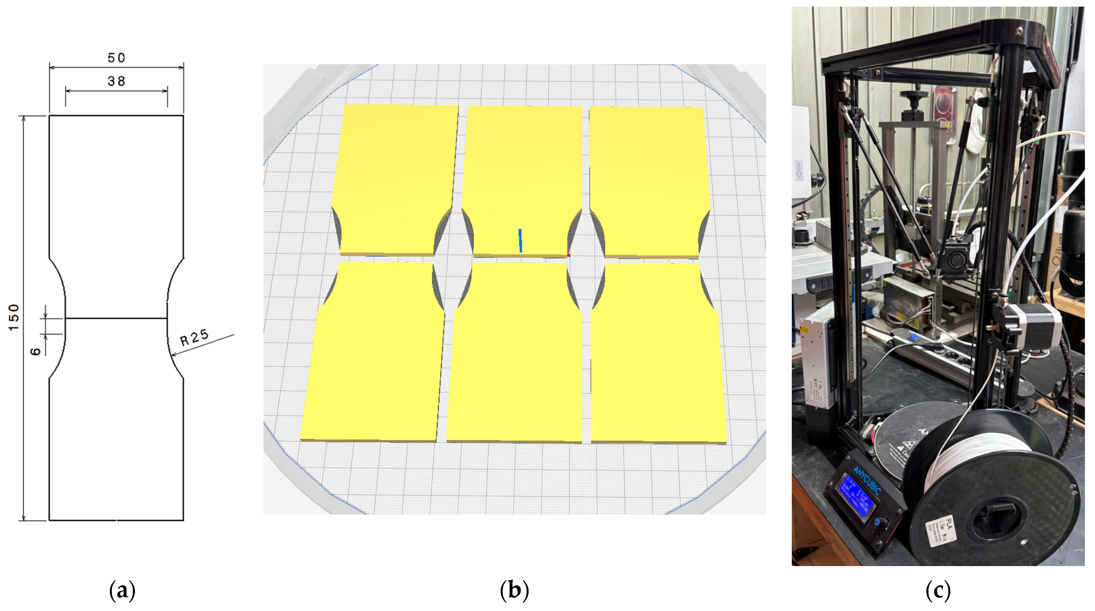
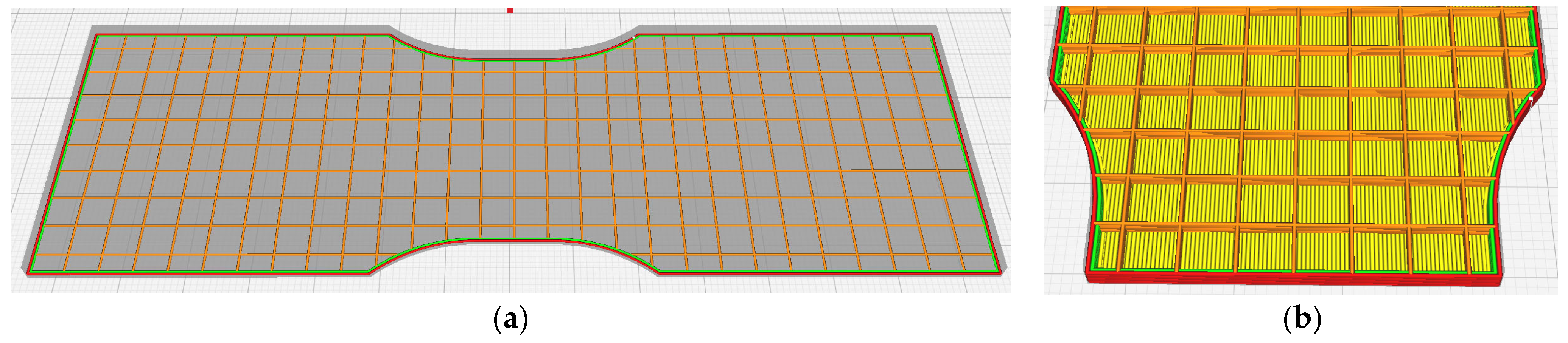
2.1. Welding Process Setup

The setup allowed the precise control of rotational speed, the tool’s tilt angle, and welding speed. For the cases with added material, the portable FSW device utilized a 3 mm diameter PLA rod as a filler material, from SmartMaterials3D (Alcalá la Real, Spain). The filler material was driven through a hole in the welding head, which rotated at a programmable speed, while the operator manually guided the tool along the joint line to form the weld.
Two tool geometries were used (Figure 3a): one with a cylindrical pin and constant cross-section, 3.4 mm in diameter, and another with a truncated conical pin, featuring a 2.2 mm tip diameter and a 4 mm base radius. Both tools were made from 6082 T6 aluminum and mounted on the FSW device (Figure 3b).
Figure 3. (a) The geometries and dimensions of the tool with a cylindrical pin (Tool 1) and with a truncated conical pin (Tool 2), respectively. (b) The tool with a cylindrical pin mounted on the welding equipment.
The fabrication parameters were configured according to supplier recommendations and the specimen’s geometry (Figure 4a) following the AWS B4.0:2016 standard [39]. The specimens were manufactured using Fused Deposition Modeling (FDM) technology and arranged as shown in Figure 4b. For this, a delta-architecture 3D printer, specifically the Anycubic Kossel Linear Plus (ANYCUBIC Technology Co., Ltd., Shenzhen, Guangdong, China) (Figure 4c), was used. To study the effect of the filling percentage on the welding process, the internal structure was printed using a grid infill pattern with two different densities: 15% and 100% [39]. Each specimen was 3 mm thick, and the edges were prepared to ensure proper alignment for butt joint welding. During the test, the tool temperature was manually measured using an infrared thermometer, Fluke 566 (Washington DC, USA).
Figure 4. (a) Specimen geometry dimensions; (b) half-specimens arranged in groups of six units on the working surface; and (c) Anycubic printer (ANYCUBIC Technology Co., Ltd., Shenzhen, China).
Figure 5 shows the internal structure of the specimens (grid infill pattern), displayed in orange (grid), oriented in perpendicular directions (0–90°) with a mesh spacing of 5.33 mm. The unwelded specimen is shown in Figure 5a, while Figure 5b shows the half specimen. Although the highest strength of the specimens is achieved with a ±45° grid, the 0–90° configuration was chosen to make the analysis of the results easier, as performed by other researchers [40,41]. Also, in Figure 5b, the inner perimeter is highlighted in green, the outer perimeter in red, and the entire specimen is represented in shaded gray, with a total thickness of 3 mm.
Figure 5. (a) The structure of an internal layer (orange) of a complete specimen with two perimeters: 15% infill density, 0–90° orientation, and a layer height of 0.2 mm. (b). The internal structure (orange) of a specimen processed with 15% infill in a 0–90° orientation.
Additionally, Table 1 shows the main parameters used during the manufacturing of the specimens using FDM.
Table 1. The main parameters for specimen printing. Each parameter group is highlighted in bold, with the corresponding values listed below for 15% and 100% infill.

2.2. Welding Parameters

The welding process of the test specimens was organized into six groups. Two of them (groups P0 and P3) were selected due to parameter variability and discrepancies found in the literature and were used to evaluate how different process conditions affect the weld. Although most of the reviewed literature suggests a tilt angle on the tool, this study also tested welding with a tilt angle of 0°, as an extreme case, in order to observe the resulting effects. Therefore, group P0 consisted of parameter tests for material addition in specimens with 15% infill and a tool tilt angle of 0°, whereas group P3 included specimens with 100% infill and a tool tilt angle of 8°.
In groups P1 and P2, the welding process was performed on specimens with 15% infill density using tool tilt angles of 0° and 8°, respectively, while varying the feed rate. Groups P0, P1, P2, and P3 were welded without a tool pin. In these cases, the filler material rod itself generated the necessary friction and heat.
The welding tests for groups P4 and P5 were performed without material addition on specimens with 100% infill, using Tool 1 and Tool 2 geometries, respectively.
The variables considered and measured during the tests are as follows:
  • Rotational speed, measured in rpm.
  • Welding speed, measured in mm/min.
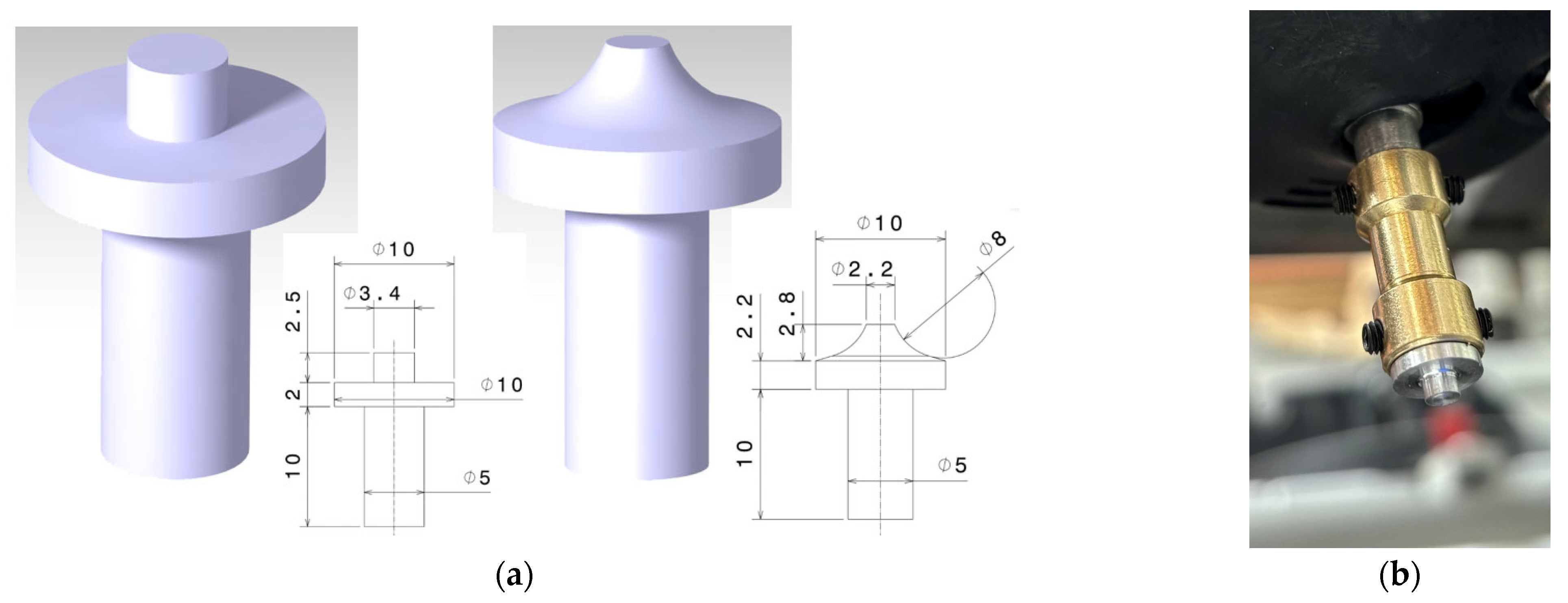
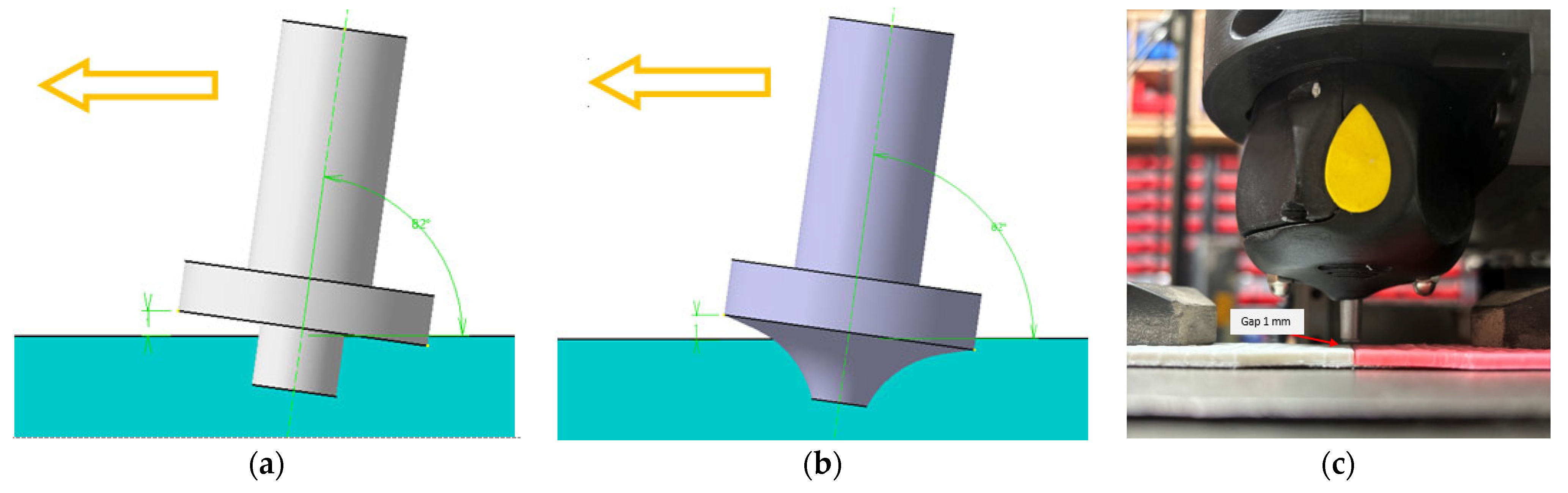
  • Tool tilt angle, measured in degrees, as shown in Figure 6a,b.
    Figure 6. (a) Tool positioning relative to the material to be welded, indicating the forward welding direction, stand-off distance (SOD), and tilt angle for (a) Tool 1 and (b) Tool 2. (c) Stand-off distance (SOD) showing a 1 mm gap.
  • Material feed speed, measured in mm/min.
  • Welding direction (forward or backward).
  • Tool temperature (only in the case of Tool 1 and Tool 2), measured in °C.
  • Stand-off distance (SOD), defined as the distance from the nozzle to the surface when material is added, measured in millimeters. A 1 mm gauge was used to determine SOD, as shown in Figure 6c.
A summary of all the variables is described in Table 2.
Table 2. A summary of the variables in the welding of test specimens. Each test group (P0 to P5) is highlighted in bold, with the corresponding specimen name and parameters listed below. Rotation speed, welding speed, tilt angle, material feed, stand-off distance (SOD), and welding direction were selected to analyze their effects on the welding process.

3. Results and Discussion

This section presents the main findings from the welding tests. The analysis begins by addressing the presence of entry and exit burrs, the degree of weld penetration, and the variation in specimen mass. We then describe the different zones identified in the welds, distinguishing between stable and transient regions. Images of the welded specimens are included to illustrate the observations.

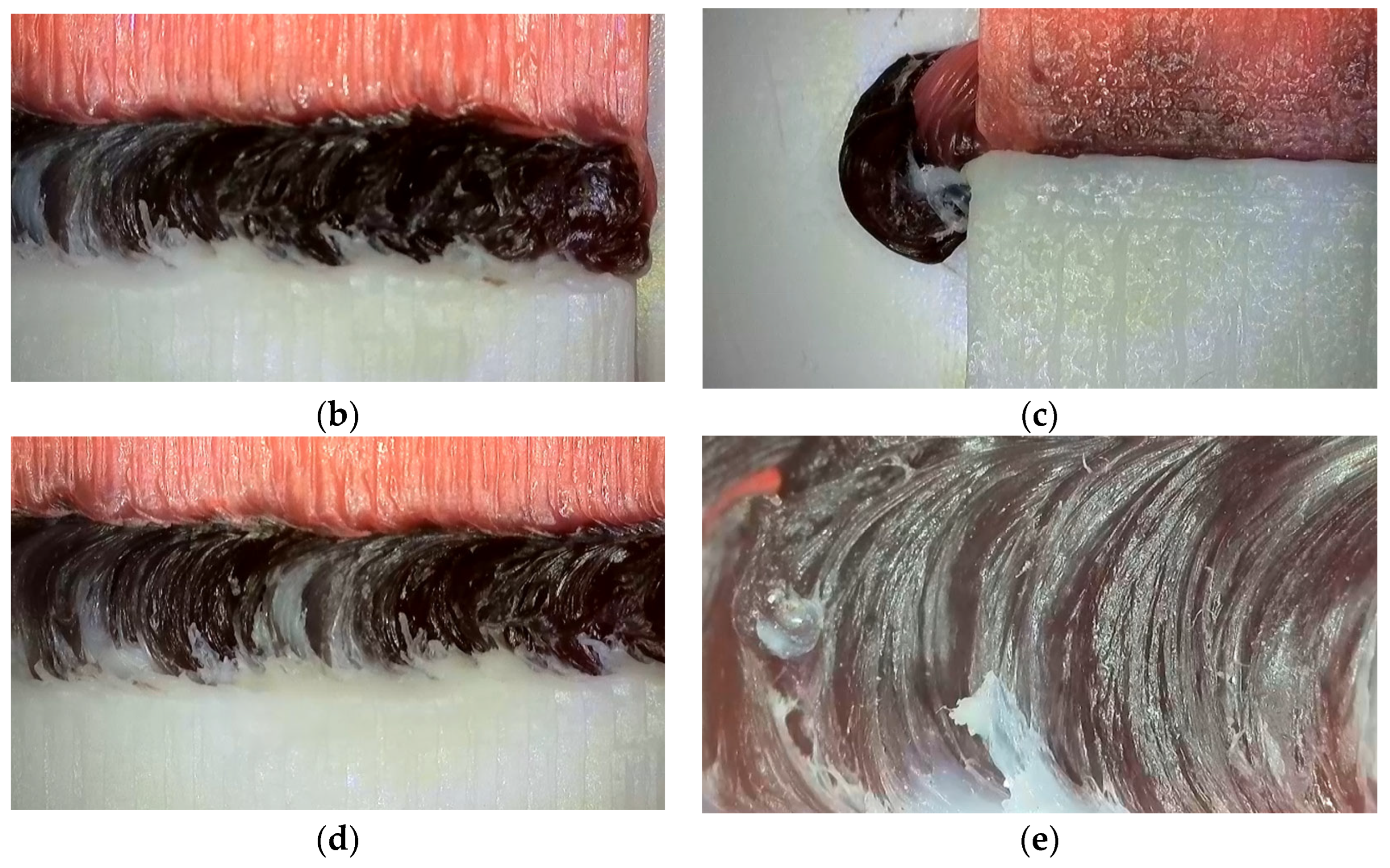
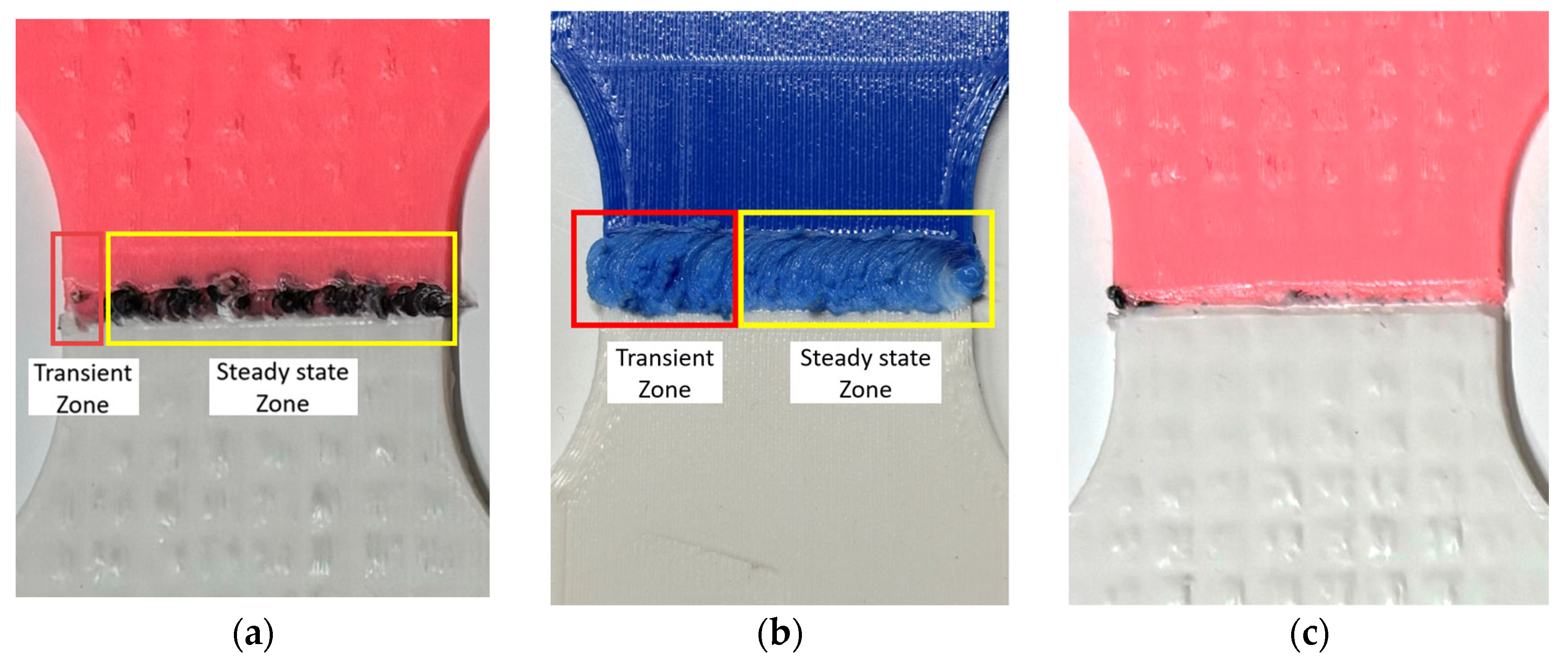
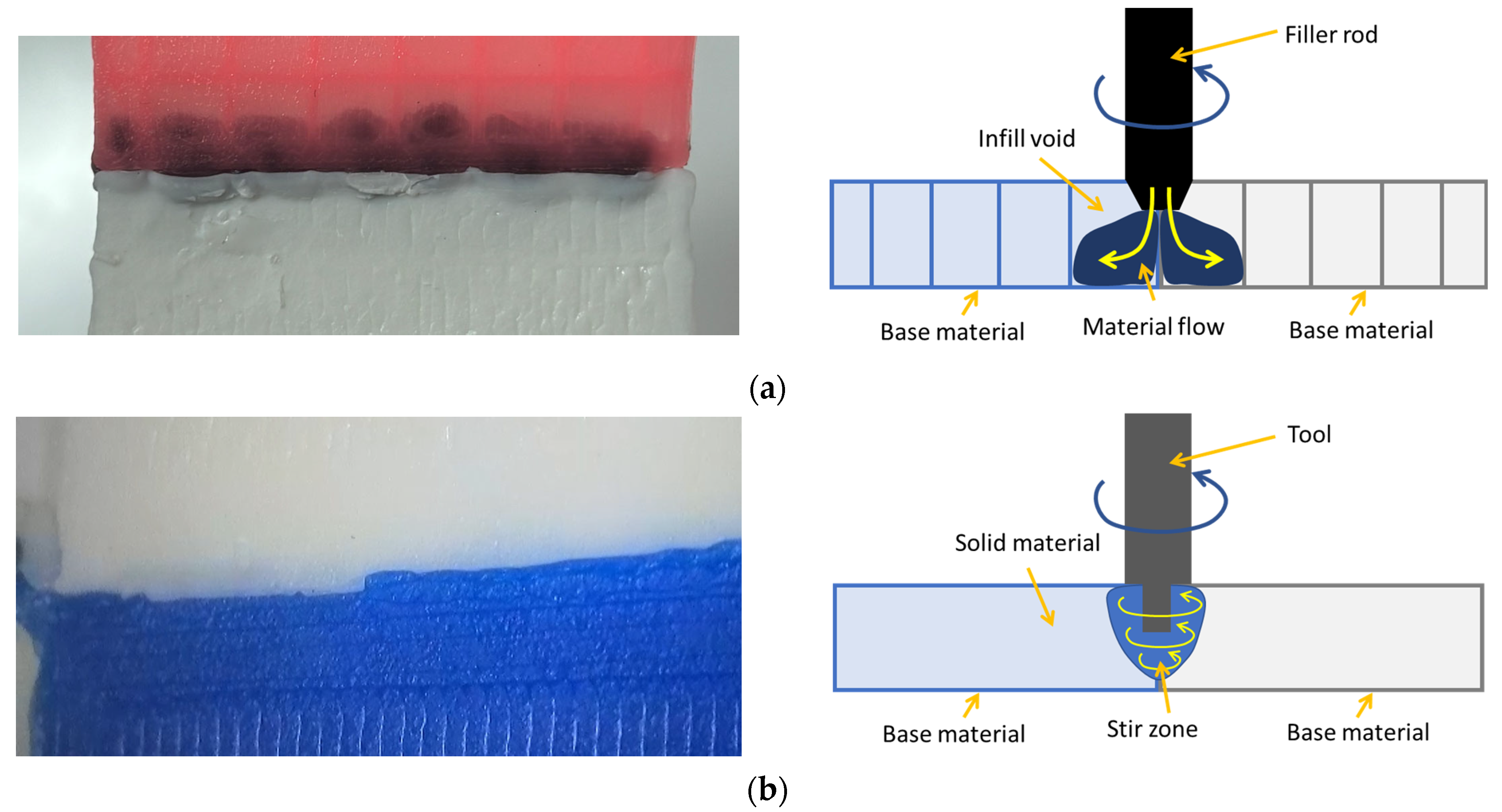
3.1. Zones, Flash, and Material Stirring

A common feature observed in all welded joints, except for the non-tilted condition, is the almost complete absence of entry flash (as shown in Figure 7a,b), while exit flash is clearly visible, as illustrated in Figure 7a,c, for a specimen from the P1 group with filler material and a tilted tool.
Figure 7. Specimen P1_2. (a) The front and bottom views of the welded specimen. (b) The absence of an entry flash on the front side. (c) The exit flash observed from the bottom side. (d) Homogeneous mixing in the central weld zone. (e) The details of the central weld zone.
Figure 7c shows an intermediate zone of the weld. Additionally, Figure 7d,e show the detail of the intermediate zone. The material mixing in this zone is noticeable, where the different colors are clearly stirred. Figure 7a shows that, on the side opposite the weld, material built up in internal areas that were not fully filled. Then, the joint is mainly composed of filler material (black), creating a clearly defined and sharp transition between the two parts. This happens because the high porosity in those regions allows the filler material to gather there. As a result, the weld zone likely ends up with less porosity than the surrounding material, which could lead to better mechanical behavior.
Two distinct stages were identified during the welding process in all the joints produced:
  • The first stage began at the start of welding and continued until the tool reached a stable temperature. During this stage, material flow was inconsistent and irregular, with no clearly defined pattern. This behavior is highlighted in red in Figure 8a,b.
    Figure 8. Transient (red) and steady-state (yellow) regime zones in (a) P2 specimens (15% infill with filler); (b) P4 specimens (100% infill without filler); and (c) P0 specimens (15% infill with filler and a non-tilted tool) showing very poor material mixing.
  • The second stage corresponded to a steady-state regime (the yellow zone in Figure 8), during which the tool temperature remained nearly constant throughout the process. At this point, the material flow became homogeneous and predictable.
Both stages were observed regardless of the specimen’s infill percentage. Figure 8a,b show a detailed view of the unstable and stable stages in 100%-filled and 15%-filled specimens, respectively. These stages were also evident in the welding equipment’s behavior. During the transient regime, a slight drop in the main motor’s rotation speed was observed, caused by the increased energy demand needed to heat the tool. Once the steady-state regime was reached, the tool operated at a slightly higher and more stable speed.
Then, the length of the first stage was longer for specimens with a higher infill density, as these required more energy to initiate material flow due to the higher temperatures reached.
Regarding the non-tilted welding condition (P0 specimens), very poor material mixing was found, as shown in Figure 8c. Although the filler rod heated and plasticized the weld zone, the plastic material flow was enough to create the joint. These findings were also reported in ref. [42], where low angles were associated with insufficient material flow, and a void was created.
It was observed that the specimens that were welded at slower welding speeds showed shorter transient regime zones. Therefore, it was found that the temperature in the tool reached stable values faster at lower welding speeds. This can be explained by considering that a lower speed implies a longer tool-material friction time, which generates the preheating of the tool and the welding zones.
Then, the transient zone could be shortened by reducing the feed rate during the initial welding phase, or in other words, when the travel speed is delayed until the tool reaches a stable temperature. Otherwise, to achieve a homogeneous result along the entire seam, a preheating phase should be conducted. This can be performed by significantly reducing the feed rate at the start of the process until the tool reaches a stable working temperature.
In group P3 (100% infill with filler), the analysis of the three rotational speeds allowed us to conclude that the highest value gave the best results. Figure 9 shows the results of the increasing rotational speeds: 2000 rpm (left), 2300 rpm (center), and 2500 rpm (right). As the rotational speed increases, the weld quality tends to improve. This is likely due to the more intense stirring of the material, driven by greater frictional forces, which, in turn, generate more heat during the process. In the same group, the analysis of the welding direction highlighted the fact that the welding direction must be set forward. The test performed with a negative inclination in the movement direction results in poor-quality welds with a significant cross-sectional reduction, as shown in Figure 10a,b, respectively. According to other researchers, the forward direction increases friction and heat generation, and consequently enhances material stirring [43].
Figure 9. Specimens from group P3 with increasing rotational speeds, 2000 rpm (left), 2300 rpm (center), and 2500 rpm (right), showing a progressive improvement in weld quality.
Figure 10. The results of setting the welding in the backward direction, with a high number of burrs (a) and an important cross-section reduction (b).

3.2. Penetration

Regarding weld penetration, there was a noticeable difference between the 15%-infilled specimens and the 100%-infilled specimens. Figure 11a (left) shows the effect of stirring on the underside of the specimen in the dark areas inside the base materials. The material, compressed by the tool’s pressure, flowed downward and laterally, penetrating both sides of the weld, which is slightly visible to the naked eye, as illustrated in Figure 11a (right). Once the specimen walls were stirred, the material tended to flow and fill the voids in the base material.
Figure 11. (a) The bottom view of the specimen P2_3 (left) and a schematic representation of the material flow from the filler rod to the material voids, which is visible from the bottom side; (b) the bottom view of the specimen P5_3 (left) and a schematic representation of the stir zone, which is visible from the bottom side.
This effect was not observed in the welding of solid specimens without filler material (Figure 11b, left) because the transversal flow was restricted, and there were no empty regions within the material to accommodate the displaced mass (Figure 11b, right). However, near the weld seam, a deep fusion zone is clearly visible from the bottom view. This is noticeable in the white area where bluish tones appear, indicating that the blue material has been mixed into the white region (Figure 11b, right). Therefore, for low-density base materials, additional material must be supplied to achieve a good result, whereas it may not be necessary for high-density materials.

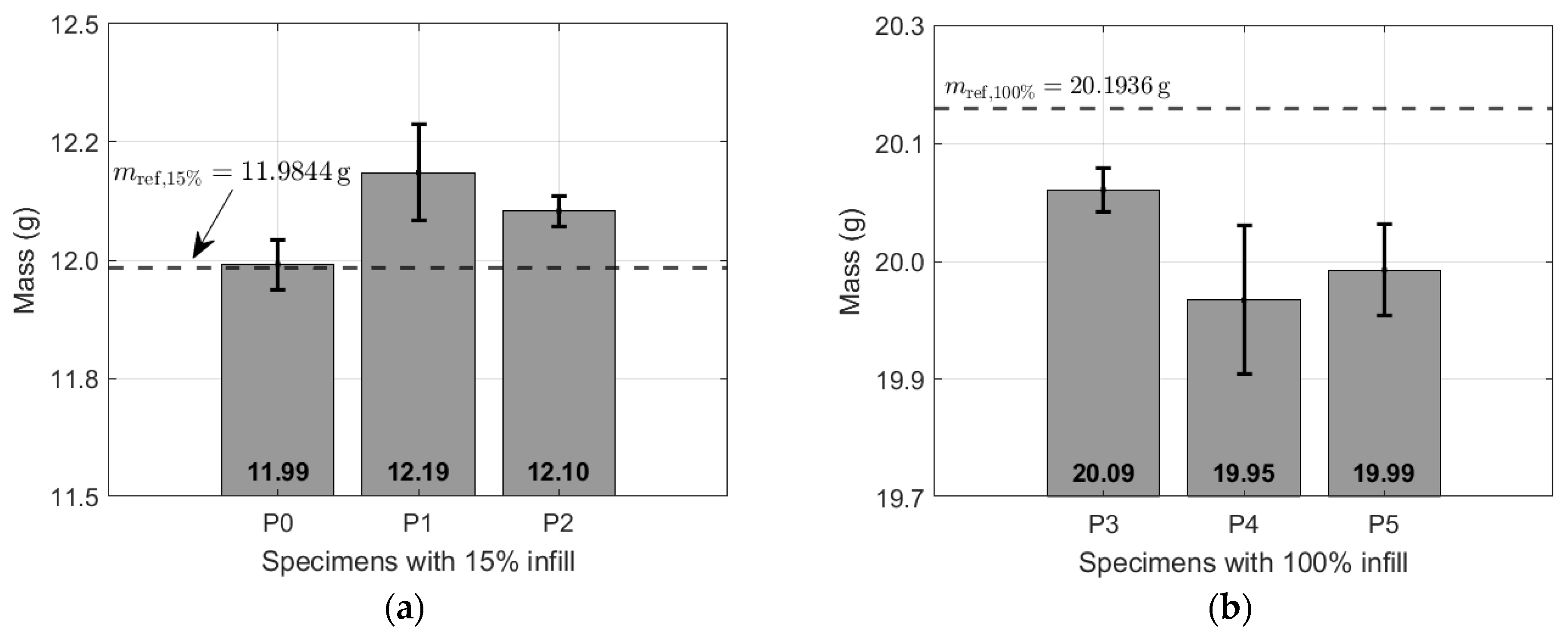
3.3. Mass Determination and Material Loss

The mass of the specimens was measured before and after welding in order to determine the amount of filler material added and the material loss in the form of chips. The mass of all specimens was measured before welding in pairs. Then, the reference unwelded masses were 11.9844 ± 0.0355 g and 20.1936 ± 0.0363 g for the 15% and 100% infill percentages, respectively. The results of the masses for each pair are shown in Table 3. Data comparison with the reference is also shown in Figure 12a,b in a bar and box-and-whisker plot.
Table 3. The mass of test specimens across different groups. Each group of specimens is highlighted in bold. The mass of each specimen is listed, along with the average and standard deviation below. The table includes specimens with both 15% and 100% infill.
Figure 12. The mass of the specimen with (a) 15% infill with filler material and (b) 100% infill with filler material (P3) and without filler material (P4 and P5).
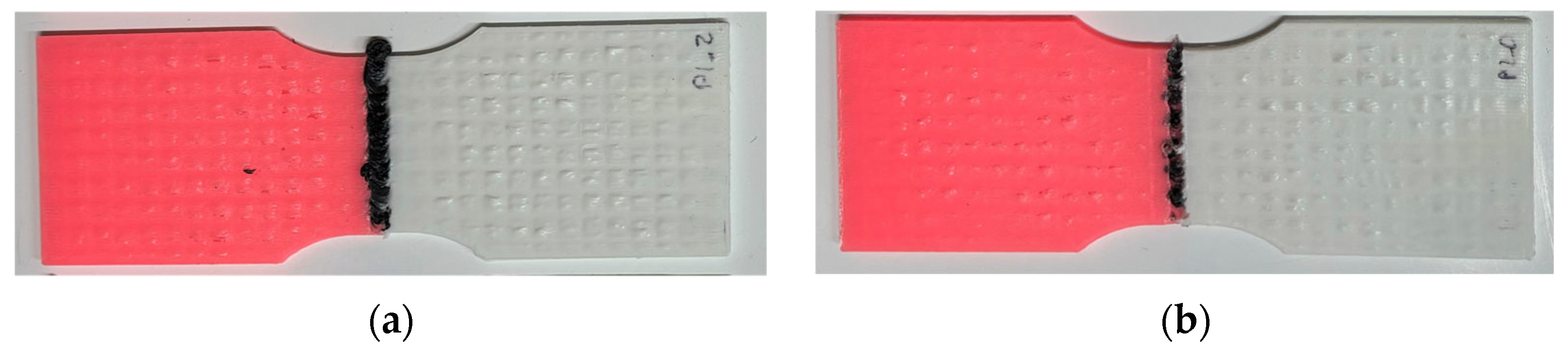
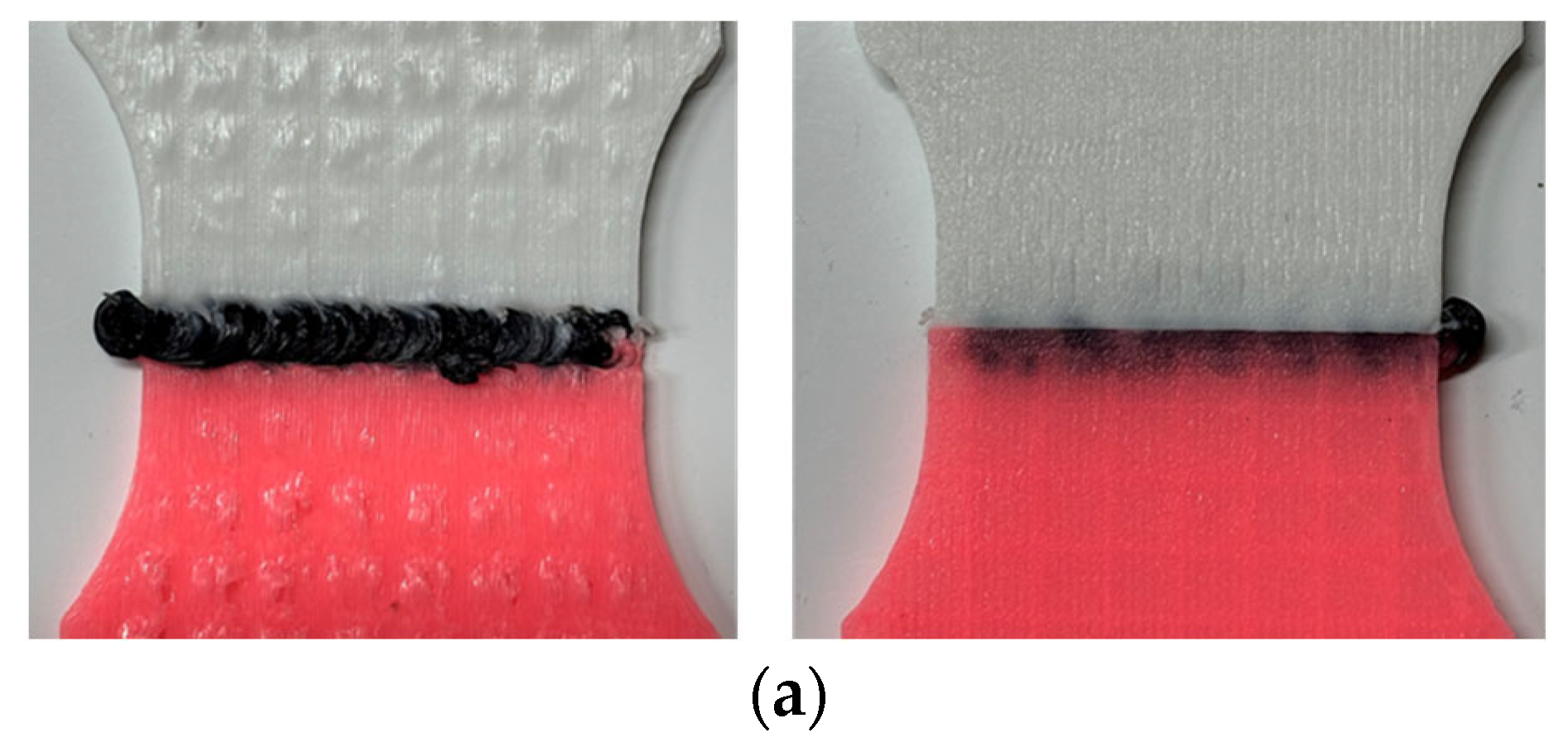
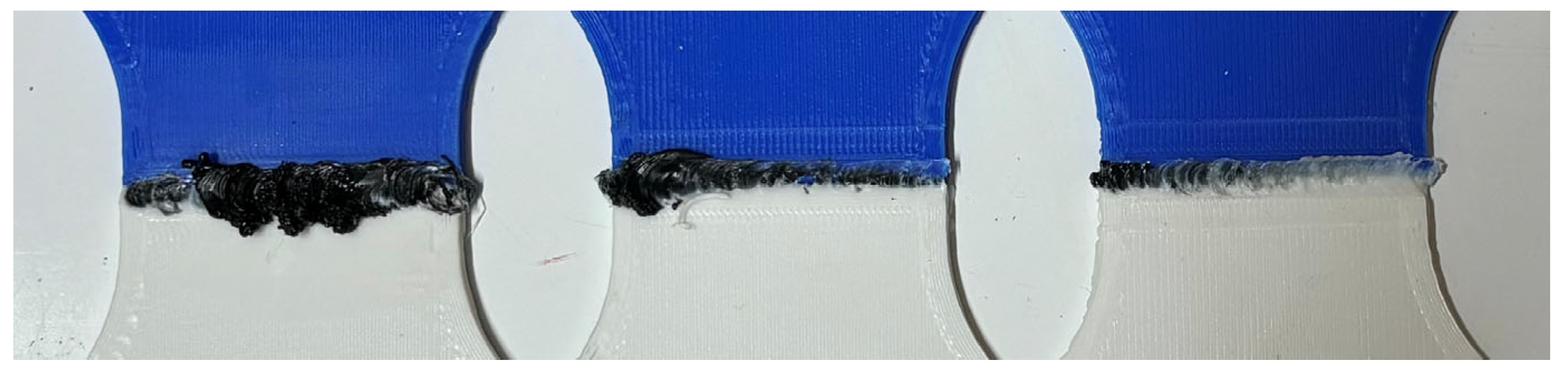
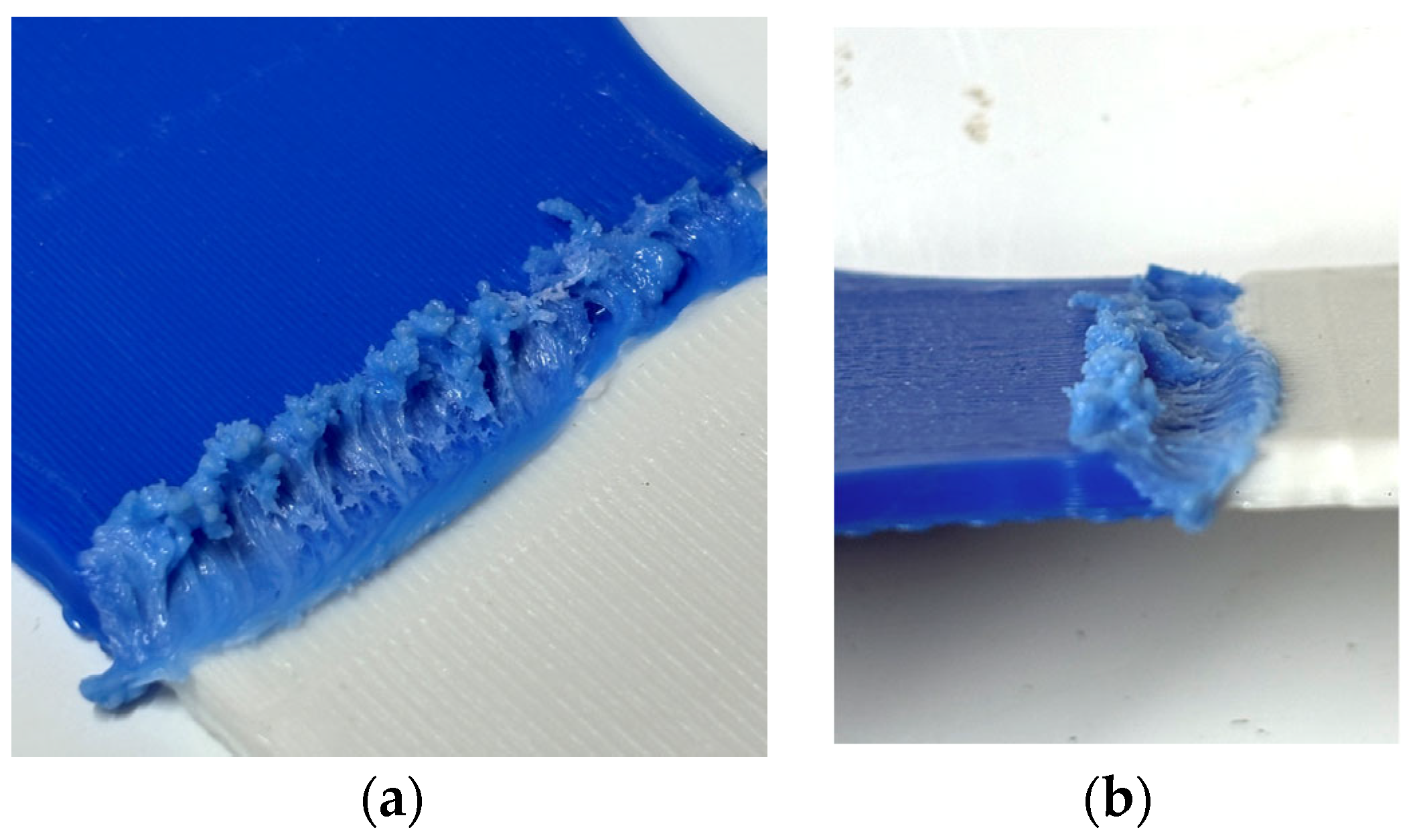
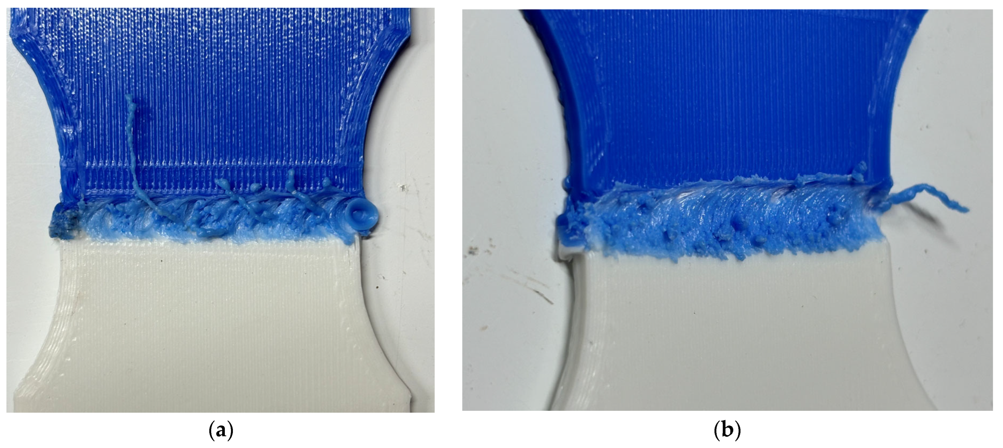
  • In Figure 12a, the dashed line indicates the reference value, confirming that in the P0 specimen group, very little filler material was added, as the lack of tool inclination prevented the flow of the filler material, as previously shown in Figure 8c. In the P1 specimens, with 15% infill and filler rod, a noticeable mass increment was reported. In the P2 specimens, the amount of filler material added was slightly less than that in the P1 group, which was due to the narrower weld caused by the increased travel speed. The mean width of the weld for low and high welding speeds was 5.42 and 3.22 mm, respectively. This effect is clearly visible in Figure 13a,b, where the black weld lines highlight the width differences. When the filler material flow rate was kept constant, higher welding speeds produced narrower weld lines to distribute the total added mass. ANOVA analysis on the specimen mass revealed statistically significant differences between the three groups (p < 0.05).
Figure 13. Specimens with 15% infill density from groups P1 (a) and P2 (b) welded at low and high speeds, respectively, showing a visible difference in weld width.
Similarly, for the specimens with 100% infill density, the results are shown in Figure 12b. As expected, the mass of the specimens where filler material was added (test P3) was slightly higher, but still less than the base material mass. This means that during welding, more material was lost than gained. Significant differences were observed between P3 and the other two groups (p < 0.05), P4 and P5. In cases without filler, groups P4 and P5, using cylindrical and conical tools, respectively, it initially seemed that the cylindrical pin tool caused more chips to be ejected outside the weld. However, the results suggest that this assumption cannot be confirmed, given the close values and high variability observed (p > 0.05). Additionally, many of the chips (burrs) produced by the cylindrical pin tool remained attached to the weld on the retreat side, but outside the weld bead, meaning that they did not contribute to joint strength and worsened the surface’s finish (Figure 14a). In the case of a truncated cone tool, the number of burrs is lower (Figure 14b). Although no significant differences in mass variation were found between the two tools (p > 0.05), differences in weld homogeneity were evident. The truncated cone tool produced more uniform welds and achieved better mixing of the material. In Figure 14b, the white material can be seen inside the blue part.
Figure 14. Weld surface and chips generation observed in specimens (a) P5_0 and (b) P5_2.
Although this work aimed to provide a general understanding of the behavior of the most relevant parameters in the welding process, based on the literature, it is important to further explore and expand on the scope of its application. In this context, the potential implementation of the FSW system in an automated setup, such as a general-purpose robotic arm or a tool specifically designed to weld a particular component, stands out as particularly relevant. This can expand the range of applications and facilitate its transfer to the industrial sector, allowing for tighter control over various parameters and weld quality. Additionally, integrating different sensors and process monitoring could provide valuable insights into the complex phenomena involved, including heat transfer, rheological behavior, and defect formation.

4. Conclusions

The study shows the technical and operational feasibility of a portable Friction Stir Welding device developed specifically for joining components manufactured by additive manufacturing (AM). Specifically, using thermoplastic polymers of the polylactic acid (PLA) type. After carrying out the tests and analyzing the results, the main findings from this study are as follows:
  • The combination of FSW and AM technologies for thermoplastics could be an efficient alternative for joining AM parts with complex geometries and in situ repairs.
  • During the welding, the FSW process revealed two different phases: a transient stage and a steady-state stage. The latter is characterized by a homogeneous and predictable material flow, while the former shows irregular material distribution. The length of the transient stage was longer for specimens with higher infill densities.
  • In samples with a lower infill (15%) and added filler, the weld zone was mostly composed of filler material, with only minimal melting of the base material. In these cases, the internal voids were easily occupied by the filler material flowing into them. In contrast, in the samples with 100% infill, the stirred material flowed more homogeneously, and no filler was required. Therefore, for low-density base materials, additional material must be supplied to achieve a good result, whereas it may not be necessary for high-density materials.
  • In the Friction Stir Welding process of PLA components without material addition, a reduction in the total component mass occurred due to the formation of burrs.
  • Increasing the feed rate resulted in a narrower welded joint. When the filler material flow rate was kept constant, higher welding speeds produced narrower weld lines to distribute the total added mass.
  • Tool inclination plays a key role in the process, as confirmed by both the results obtained in this study and other researchers.
  • The analysis of the welding direction highlighted that the welding direction must be set forward. The test performed with a negative inclination in the movement direction resulted in poor-quality welds with significant cross-sectional reduction. The forward direction increases friction and heat generation and consequently enhances material stirring.
  • When the cylindrical pin and the truncated conical welding tool were compared, the truncated conical tool resulted in fewer burrs, reduced mass loss, and fewer defects, producing a more homogeneous weld line. Visual inspection also indicated a higher level of material stirring with the truncated conical tool, which presumably contributes to improved weld quality.
  • The analysis of rotational speed showed that increasing it from 2000 rpm to 2500 rpm led to a noticeable improvement in weld quality.
  • Overall, the results suggest that this portable device holds great promise for industrial applications that demand mobility, flexible operation, and strong, reliable welds on 3D-printed polymer parts. This is particularly relevant in fields like aerospace, automotive, and medical industries, where the integration of additive manufacturing and solid-state joining technologies is becoming increasingly important.
  • Future work should focus on automating the FSW process for additive manufacturing polymers, which would improve control over welding parameters and quality. Additionally, integrating sensors for in situ monitoring could provide deeper insight into heat transfer, material behavior, and defect formation during welding.
In conclusion, these findings highlight the potential of using FSW as a feasible joining method for polymer parts made via AM. This study lays the groundwork for future research aimed at industrial scale-up and the exploration of other types of polymers and processing conditions.

5. Patents

The novel Friction Stir Welding (FSW) device is protected by patent ES2952553.

Author Contributions

Conceptualization, M.Á.A.; methodology, M.Á.A.; validation, M.M., E.M.R., and J.A.A.; formal analysis, M.Á.A.; investigation, M.Á.A.; resources, M.Á.A., M.M., J.A.A., A.G.-D., and E.M.R.; data curation, M.Á.A., M.M., J.A.A., A.G.-D., and E.M.R.; writing—original draft preparation, M.Á.A.; writing—review and editing, M.Á.A., M.M., J.A.A., A.G.-D., and E.M.R.; visualization, M.Á.A.; supervision, M.M. and E.M.R.; project administration, M.M. and E.M.R. All authors have read and agreed to the published version of the manuscript.

Funding

This research received no external funding.

Data Availability Statement

The raw data supporting the conclusions of this article will be made available by the authors on request.

Acknowledgments

The authors are grateful for the support of the Industrial Production and Manufacturing Engineering (IPME) Research Group, the Innovation and Teaching Group for Industrial Technologies in Productive Environments (TIA Plus UNED), and the Master of Manufacturing Advanced Engineering.

Conflicts of Interest

The authors declare no conflicts of interest.

References

  1. Groover, M.P. Fundamentals of Modern Manufacturing: Material, Processes, and Systems, 7th ed.; John Wiley and Sons: Hoboken, NJ, USA, 2016. [Google Scholar]
  2. Porras, P. Análisis y Estudio Del Proceso de Soldadura Por Fricción y Agitación; Universidad Nacional de Estudios a Distancia (UNED): Madrid, Spain, 2018. [Google Scholar]
  3. Zhou, L.; Liu, D.; Nakata, K.; Tsumura, T.; Fujii, H.; Ikeuchi, K.; Michishita, Y.; Fujiya, Y.; Morimoto, M. New Technique of Self-Refilling Friction Stir Welding to Repair Keyhole. Sci. Technol. Weld. Join. 2012, 17, 649–655. [Google Scholar] [CrossRef]
  4. Shravan, C.; Radhika, N.; Kumar, N.H.D.; Sivasailam, B. A Review on Welding Techniques: Properties, Characterisations and Engineering Applications. Adv. Mater. Process. Technol. 2024, 10, 1126–1181. [Google Scholar] [CrossRef]
  5. Bohnart, E.R. Welding Principles and Practices, 6th ed.; Mc Graw Hill: New York, NY, USA, 2024. [Google Scholar]
  6. Mishra, R.S.; Ma, Z.Y. Friction Stir Welding and Processing. Mater. Sci. Eng. R Rep. 2005, 50, 1–78. [Google Scholar] [CrossRef]
  7. Houldcroft, P.T.; Feng; Fim; Fweldi. Welding Process Developments and Future Trends. Mater. Des. 1986, 7, 162–169. [Google Scholar] [CrossRef]
  8. Elatharasan, G.; Kumar, V.S.S. An Experimental Analysis and Optimization of Process Parameter on Friction Stir Welding of AA 6061-T6 Aluminum Alloy Using RSM. Procedia Eng. 2013, 64, 1227–1234. [Google Scholar] [CrossRef]
  9. Lambiase, F.; Derazkola, H.A.; Simchi, A. Friction Stir Welding and Friction Spot Stir Welding Processes of Polymers—State of the Art. Materials 2020, 13, 2291. [Google Scholar] [CrossRef] [PubMed]
  10. Kiss, Z. Microscopic Analysis of the Morphology of Seams in Friction Stir Welded Polypropylene. Express Polym. Lett. 2011, 6, 54–62. [Google Scholar] [CrossRef]
  11. Cai, W.; Daehn, G.; Vivek, A.; Li, J.; Khan, H.; Mishra, R.S.; Komarasamy, M. A State-of-the-Art Review on Solid-State Metal Joining. J. Manuf. Sci. Eng. 2019, 141, 031012. [Google Scholar] [CrossRef]
  12. Verma, S.; Misra, J.P. A Critical Review of Friction Stir Welding Process. In DAAAM International Scientific Book; DAAAM International: Vienna, Austria, 2015; pp. 249–266. ISBN 9783902734051. [Google Scholar]
  13. Sharma, A.K.R.; Roy Choudhury, M.; Debnath, K. Experimental Investigation of Friction Stir Welding of PLA. Weld. World 2020, 64, 1011–1021. [Google Scholar] [CrossRef]
  14. Mendes, N.; Neto, P.; Loureiro, A.; Moreira, A.P. Machines and Control Systems for Friction Stir Welding: A Review. Mater. Des. 2016, 90, 256–265. [Google Scholar] [CrossRef]
  15. Gebhardt, A. Understanding Additive Manufacturing; Hanser: München, Germany, 2011; ISBN 978-3-446-42552-1. [Google Scholar]
  16. Gibson, I.; Rosen, D.; Stucker, B. Additive Manufacturing Technologies: 3D Printing, Rapid Prototyping, and Direct Digital Manufacturing, 2nd ed.; Springer: New York, NY, USA, 2015; ISBN 9781493921133. [Google Scholar]
  17. Azlin, M.N.M.; Ilyas, R.A.; Zuhri, M.Y.M.; Sapuan, S.M.; Harussani, M.M.; Sharma, S.; Nordin, A.H.; Nurazzi, N.M.; Afiqah, A.N. 3D Printing and Shaping Polymers, Composites, and Nanocomposites: A Review. Polymers 2022, 14, 180. [Google Scholar] [CrossRef] [PubMed]
  18. Lee, J.W.; Kim, J.Y.; Cho, D.W. Solid Free-Form Fabrication Technology and Its Application to Bone Tissue Engineering. Int. J. Stem Cells 2010, 3, 85–95. [Google Scholar] [CrossRef] [PubMed]
  19. Tiwary, V.; Ravi, N.; Arunkumar, P.; Shivamurthy, S.; Deshpande, A.; Malik, V. Investigations on Friction Stir Joining of 3D Printed Parts to Overcome Bed Size Limitation and Enhance Joint Quality for Unmanned Aircraft Systems. Proc. Inst. Mech. Eng. C J. Mech. Eng. Sci. 2020, 234, 4857–4871. [Google Scholar] [CrossRef]
  20. Stephen Leon, J.; Jayakumar, V. Effect of Tool Shoulder and Pin Cone Angles in Friction Stir Welding Using Non-Circular Tool Pin. J. Appl. Comput. Mech. 2020, 6, 554–563. [Google Scholar] [CrossRef]
  21. Bilici, M.K.; Yükler, A.İ. Influence of Tool Geometry and Process Parameters on Macrostructure and Static Strength in Friction Stir Spot Welded Polyethylene Sheets. Mater. Des. 2012, 33, 145–152. [Google Scholar] [CrossRef]
  22. Estefani, A.; Távara, L. Numerical Multiscale Analysis of 3D Printed Short Fiber Composites Parts: Filament Anisotropy and Toolpath Effects. Eng. Rep. 2024, 6, e12799. [Google Scholar] [CrossRef]
  23. Wang, X.; Hua, Z.; Chen, G. Research on the Anisotropy of Mechanical Properties of Powder-Based 3D Printed Models After Dipping. In Advances in Graphic Communication, Printing and Packaging Technology and Materials: Proceedings of 2020 11th China Academic Conference on Printing and Packaging; Zhao, P., Ye, Z., Xu, M., Yang, L., Zhang, L., Zhu, R., Eds.; Springer: Singapore, 2021; pp. 352–357. [Google Scholar]
  24. Liu, J.; Zhou, Y.; Chen, S.; Ren, S.; Zou, J. Effects of Friction Stir Welding on the Mechanical Behaviors of Extrusion-Based Additive Manufactured Polymer Parts. Polymers 2023, 15, 3288. [Google Scholar] [CrossRef] [PubMed]
  25. Pereira, M.A.R.; Amaro, A.M.; Reis, P.N.B.; Loureiro, A. Effect of Friction Stir Welding Techniques and Parameters on Polymers Joint Efficiency—A Critical Review. Polymers 2021, 13, 2056. [Google Scholar] [CrossRef] [PubMed]
  26. Petousis, M.; Mountakis, N.; Vidakis, N. Optimization of Hybrid Friction Stir Welding of PMMA: 3D-Printed Parts and Conventional Sheets Welding Efficiency in Single- and Two-Axis Welding Traces. Int. J. Adv. Manuf. Technol. 2023, 127, 2401–2423. [Google Scholar] [CrossRef]
  27. Vidakis, N.; Petousis, M.; Korlos, A.; Mountakis, N.; Kechagias, J.D. Friction Stir Welding Optimization of 3D-Printed Acrylonitrile Butadiene Styrene in Hybrid Additive Manufacturing. Polymers 2022, 14, 2474. [Google Scholar] [CrossRef] [PubMed]
  28. Javadi, M.S.; Ehteshamfar, M.V.; Adibi, H. A Comprehensive Analysis and Prediction of the Effect of Groove Shape and Volume Fraction of Multi-Walled Carbon Nanotubes on the Polymer 3D-Printed Parts in the Friction Stir Welding Process. Polym. Test. 2023, 117, 107844. [Google Scholar] [CrossRef]
  29. Rendas, P.; Figueiredo, L.; Melo, P.; Galhano, C.; Vidal, C.; Soares, B.A.R. Investigation of Friction Stir Welding of Additively Manufactured Biocompatible Thermoplastics Using Stationary Shoulder and Assisted Heating. Polymers 2024, 16, 1897. [Google Scholar] [CrossRef] [PubMed]
  30. Koçar, O.; Anaç, N.; Baysal, E. A New Approach in Part Design for Friction Stir Welding of 3D-Printed Parts with Different Infill Ratios and Colors. Polymers 2024, 16, 1790. [Google Scholar] [CrossRef] [PubMed]
  31. Vidakis, N.; David, C.; Petousis, M.; Sagris, D.; Mountakis, N. Optimization of Key Quality Indicators in Material Extrusion 3D Printing of Acrylonitrile Butadiene Styrene: The Impact of Critical Process Control Parameters on the Surface Roughness, Dimensional Accuracy, and Porosity. Mater. Today Commun. 2023, 34, 105171. [Google Scholar] [CrossRef]
  32. Moochani, A.; Omidvar, H.; Ghaffarian, S.R.; Goushegir, S.M. Friction Stir Welding of Thermoplastics with a New Heat-Assisted Tool Design: Mechanical Properties and Microstructure. Weld. World 2019, 63, 181–190. [Google Scholar] [CrossRef]
  33. Anaç, N.; Koçar, O.; Altuok, C. Investigation of The Weldability of PLA Plus Sheets with Different Infill Ratios by Friction Stir Welding. Gazi Üniversitesi Fen Bilim. Derg. Part C Tasarım Ve Teknol. 2024, 12, 282–296. [Google Scholar] [CrossRef]
  34. Kumar, R.; Ranjan, N.; Kumar, V.; Kumar, R.; Chohan, J.S.; Yadav, A.; Piyush; Sharma, S.; Prakash, C.; Singh, S.; et al. Characterization of Friction Stir-Welded Polylactic Acid/Aluminum Composite Primed through Fused Filament Fabrication. J. Mater. Eng. Perform. 2022, 31, 2391–2409. [Google Scholar] [CrossRef]
  35. Senthil, S.M.; Bhuvanesh Kumar, M. Effect of Tool Rotational Speed and Traverse Speed on Friction Stir Welding of 3D-Printed Polylactic Acid Material. Appl. Sci. Eng. Prog. 2021, 15, 1. [Google Scholar] [CrossRef]
  36. Valerga, A.; Batista Ponce, M.; Salguero, J.; Girot, F. Influence of PLA Filament Conditions on Characteristics of FDM Parts. Materials 2018, 11, 1322. [Google Scholar] [CrossRef] [PubMed]
  37. López-Alba, E.; Almazán-Lázaro, J.-A.; Díaz-Garrido, F.-A.; Almazán-Lázaro, M.-Á. Dispositivo Portátil de Soldadura. Spanish Patent No. ES2952553B2, 27 June 2024. [Google Scholar]
  38. Smart Materials 3D. Available online: https://www.smartmaterials3d.com/ (accessed on 24 October 2024).
  39. ANSI-AWS B4.0:2016; Standard Methods for Mechanical Testing of Welds. American National Standards Institute: Washington, DC, USA, 2016.
  40. Kocar, O.; Anaç, N.; Palaniappan, S.; Doğan, M.; Siengchin, S. Effect of Process Parameters on the Mechanical Behavior of Additively Manufactured and FSW Joined PLA Wood Sheets. Polym. Compos. 2023, 45, 1568–1584. [Google Scholar] [CrossRef]
  41. Vosynek, P.; Navrat, T.; Krejbychova, A.; Palousek, D. Influence of Process Parameters.of Printing on Mechanical Properties of Plastic Parts Produced by FDM 3D Printing Technology. MATEC Web Conf. 2018, 237, 02014. [Google Scholar] [CrossRef]
  42. Wang, X.; Xiao, Y.; Shi, L.; Zhai, M.; Wu, C.; Chen, G. Revealing the Mechanism of Tool Tilting on Suppressing the Formation of Void Defects in Friction Stir Welding. J. Mater. Res. Technol. 2023, 25, 38–54. [Google Scholar] [CrossRef]
  43. Zadpoor, A.A.; Sinke, J.; Benedictus, R. Global and Local Mechanical Properties and Microstructure of Friction Stir Welds with Dissimilar Materials and/or Thicknesses. Metall. Mater. Trans. A 2010, 41, 3365–3378. [Google Scholar] [CrossRef]
Disclaimer/Publisher’s Note: The statements, opinions and data contained in all publications are solely those of the individual author(s) and contributor(s) and not of MDPI and/or the editor(s). MDPI and/or the editor(s) disclaim responsibility for any injury to people or property resulting from any ideas, methods, instructions or products referred to in the content.

Article Metrics

Citations

Article Access Statistics

Multiple requests from the same IP address are counted as one view.