Article

Establishing Linearity of the MOSkin Detector for Ultra-High Dose-per-Pulse, Very-High-Energy Electron Radiotherapy Using Dose-Rate-Corrected EBT-XD Film

1
Centre for Medical Radiation Physics, University of Wollongong, Wollongong, NSW 2522, Australia
2
Australian Synchrotron, Australian Nuclear Science and Technology Organisation, Melbourne, VIC 3168, Australia
3
Department of Physical Sciences, Peter MacCallum Cancer Centre, East Bentleigh, VIC 3165, Australia
4
Cancer Care Centre, Department of Medical Physics, St. George Hospital, Kogarah, NSW 2217, Australia
5
Australian Centre for Neutron Scattering, Australian Nuclear Science and Technology Organisation, Lucas Heights, NSW 2234, Australia
6
Australian Radiation Protection and Nuclear Safety Agency, Yallambie, VIC 3085, Australia
*
Authors to whom correspondence should be addressed.
These authors contributed equally to this work.
Appl. Sci. 2025, 15(14), 8101; https://doi.org/10.3390/app15148101
Submission received: 6 June 2025 / Revised: 14 July 2025 / Accepted: 17 July 2025 / Published: 21 July 2025

Abstract

Very-high-energy electrons, coupled with ultra-high dose rates, are being explored for their potential use in radiotherapy to treat deep-seated tumours. The dose per pulse needed to achieve ultra-high dose rates far exceeds the limit of current medical linear accelerator capabilities. A high dose per pulse has been observed as the limiting factor for many existing dosimeters, resulting in saturation at doses far below what is required. The MOSkin, an existing clinical quality assurance dosimeter, has previously been demonstrated as dose rate independent but has not been subjected to a high dose per pulse. Within this study, the MOSkins dose-per-pulse response was tested for linearity, with a dose per pulse as high as 23 Gy within 200 ns at the ANSTO Australian Synchrotron’s Pulsed Energetic Electrons for Research facility. While using EBT-XD film as a reference dosimeter, a dose rate dependence of the EBT-XD was discovered. Once confirmed and a correction factor established, EBT-XD was used as an independent reference measurement. This work presents confirmation of the MOSkin suitability for ultra-high dose-rate environments with an electron energy of 100 MeV, and a theoretical discussion of its dose-rate and dose-per-pulse independence; the MOSkin is the only detector suitable for both clinical quality assurance, and ultra-high dose-rate measurements in its standard, unmodified form.

1. Introduction

The FLASH effect, first observed in 1969 and demonstrated further over the following decade [1,2,3,4], was rediscovered in 2014 [5]. It has since been heavily investigated due to its potential for tissue sparing, while maintaining effective tumour control [6,7,8,9,10]. Using ultra-high dose rates (UHDRs), many teams have managed to reproduce the FLASH effect with protons, electrons, and X-rays [11,12,13,14]. As early as 2000, the use of very-high-energy electrons (VHEEs, electrons above 50 MeV) was suggested as a potential solution to treating deep-seated tumours [15]. More recent work has investigated this property, as well as delivering the FLASH effect, as VHEE linacs, while not designed for the purpose of radiotherapy, are generally operated with parameters that place their output firmly within the UHDR regime [16,17,18,19,20]. Currently, there are only a few facilities available to users globally. Facilities that have been made available to external research groups include the CERN Linear Electron Accelerator for Research (CLEAR) at CERN, Switzerland [21], the Accelerator Research Experiment at SINBAD (ARES) at DESY Hamburg, Germany [22], the Sources for Plasma Accelerators and Radiation Compton with Lasers and Beams (SPARC) at INFN-LNF Italy [23], the Next Linear Collider Test Accelerator (NLCTA) at SLAC in the United States [24], and, most recently, the Pulsed Energetic Electrons for Research (PEER) facility at the ANSTO Australian Synchrotron [25]. These facilities feature state-of-the-art VHEE accelerators, and have facilitated significant advances towards dosimetry capable of characterising an UHDR electron beam, as well as diagnostic tools such as current transformers [26], parameter optimisation [27], and Faraday cups [28]. However, accurate dosimetry featuring real-time measurements suitable for on-patient quality assurance is currently lacking.
There has been a consensus on the importance of reporting the temporal structure of a beam to advance understanding of the FLASH effect [29]. Most VHEE accelerators provide beams consisting of an underlying bunch structure, where bunches of charged particles delivered sequentially are referred to as a pulse, or a bunch-train [30,31], though some facilities accelerate single bunches with varied bunch repetition frequency [22]. Pulses can be delivered in either a single pulse mode, or with a pulse repetition. To realize an in vivo FLASH effect, studies have shown that two of the most important parameters are the pulse dose rate (also referred to as instantaneous dose rate, though we believe this term should be reserved for the bunch dose rate) and the average dose rate, which is related to the total time of irradiation [12,29,32,33]. While this is important for positive biological outcomes, delivering radiation at the frontiers of what is possible places strenuous demands on dosimetry and the diagnostics required for eventual, successful clinical implementation of FLASH radiotherapy. Many studies have shown that dose per pulse (DPP), rather than dose rate, may be the limiting factor for existing detectors [34,35,36,37]. As pulsed electrons consist of a bunched sub-structure on timescales orders of magnitude smaller than the pulse, the dose rate within the bunch is greater than that of the pulse. These parameters may affect not only the biological response to UHDR irradiations but also the response of detectors exposed to these extreme environments. While the radio-biological community is yet to agree on the exact parameters to induce the FLASH effect, detectors are being tested at ultra-high DPP. If a detector produces valid results within both clinical and ultra-high DPP environments, it is reasonable to expect that its performance will be equivalent within an intermediate regime if required.
Metal oxide semiconductor field-effect transistors (MOSFETs) with thin gate oxides have long been accepted as suitable devices to produce dose-rate-independent radiation detectors, confirmed by early investigations over a range of dose rates spanning 11 orders of magnitude [38]. The investigation of MOSFET detectors with thicker gate oxides is still to occur within UHDR fields, however, and is a subject of this paper. The MOSkin detector, developed by the Centre for Medical Radiation Physics (CMRP), is a MOSFET detector constructed with unique, patented technology to allow it to accurately measure the skin dose during radiotherapy [39,40,41,42,43,44,45,46,47,48,49], defined by the International Commission on Radiological Protection as the radio-sensitive basal cell layer situated at an average depth of 70 μ m [50]. Not only is the skin dose itself an important radiotherapy metric but it can also be used, if accurately measured, to assess the efficacy of the delivered treatment plans. This is an increasingly important requirement within clinical facilities; many European countries are now mandated to perform in vivo dosimetry according to the Medical Exposure Directive [51]. By adjusting the location of the detector, the MOSkin can also measure dose at any depth within a phantom or in vivo [52,53,54,55,56]. Including packaging, the entire device is approximately 300 μ m in thickness, available with a gate oxide thickness ranging from 0.55   μ m to 1.0   μ m . The thickness of the sensitive volume is used to control the sensitivity of the device. Due to its small size, the MOSkin can be attached to a patient during treatment, without impacting upon the delivered field [40,47,57]. Despite being established as dose rate independent within clinical environments [41,42] (though as with all solid-state devices, sensitivity varies with beam quality [39]), the MOSkin was later assessed for dose rate independence within an UHDR, VHEE field at the PEER beamline. Pulse dose rates spanning three orders of magnitude were delivered, and the MOSkin response was found to be independent of the dose rate [58]. However, during that period of the PEER beamline development, only low pulse charges were available to ensure the stability of the linac. Therefore, although estimated pulse dose rates were as high as 10 7 Gy/s, the maximum dose delivered in a single pulse was approximately 40 cGy, lower than what is required for eventual UHDR VHEE treatments, and not of sufficient magnitude to assess DPP independence.
While the total charge delivered within a pulse is accurately controlled at PEER, to assess the DPP independence of the MOSkin, a suitable form of energy- and dose-rate-independent reference dosimetry is required. Gafchromic film, in particular, EBT-XD [59], has been used for dosimetry in electron FLASH investigations at clinical energies [60]. The manufacturer states a <5% variance in response over an energy range of 100 keV to 18 MeV [61]. Although VHEE lies well outside this range, it is often used during VHEE dosimetric studies [62,63,64,65]. For this investigation, EBT-XD was chosen, as it is suitable for doses up to 40 Gy, covering the range of expected doses for this study. While other dosimeters have been shown to produce accurate results during VHEE studies [30,35,66,67,68], access to these devices is not readily available outside of their respective research groups. Further, the use of EBT-XD provides a means of consistency with other work in this field. However, during the course of this investigation, EBT-XD exhibited an apparent DPP dependence relative to the charge delivered by the linac. This was in contrast to the previous literature concerning its use within electron irradiations, though a slight dependence has been shown during investigation with UHDR protons [69]. A complimentary experiment was conducted to confirm this result and allow for a correction curve to be applied to all film results. Notably, during the preparation of this manuscript, independent confirmation of this effect was reported after a systematic investigation of EBT-XD performance under varying DPP and dose-rate electron fields, confirming that the film does possess the dependence observed within this study [70].
In this paper, we present further evidence of the DPP and dose rate dependence of EBT-XD film within VHEE UHDR fields. Once corrected, the film results are used to assess the DPP independence of the MOSkin detector and its linear response to increasing DPP in the 100 MeV, UHDR field at PEER. An existing model is used to present why DPP independence is an intrinsic quality of the MOSkin, within the necessary range of doses for FLASH radiotherapy, and to predict when such a dependence may occur. This work also represents further evolution of the PEER beamline, showing that accurate, repeatable irradiations can be delivered and quantified, a critical step for future VHEE experiments, from detector studies through to biological trials required for eventual clinical VHEE radiotherapy.

2. Theory and Methods

2.1. Theoretical Framework for MOSFET Detectors

We first present a brief summary of the physics behind MOSFET response to ionizing radiation and the effects of total absorbed dose upon a device. As a common electrical component, MOSFETs can also be used to detect ionizing radiation. Interested readers are referred to [71,72,73] for further information on the general operation and background of MOSFET devices. The MOSkin utilizes a p-channel MOSFET, whereby electron–hole (e-h) pairs are generated within the gate oxide when exposed to ionizing radiation. As an active dosimeter, a bias is applied to the gate during irradiation causing the holes to drift towards the Si / SiO 2 interface, where they become trapped within interface defect centres. This causes a shift in the gate threshold voltage ( Δ V ) required to pass a constant current between the source and drain terminals of the MOSFET. This shift in Δ V is proportional to the absorbed dose; the sensitivity of the device is expressed as Δ V / 1 cGy . During prolonged exposure, the accumulation of holes at the interface may lead to a decrease in sensitivity, proportional to the total accumulated dose. This decrease in sensitivity, although minimal, can be corrected if exhibited by increasing the positive bias on the gate, or by the introduction of a factor calculated from a linear fit to the decreasing sensitivity within a given beam quality [74].
The response of MOSFET detectors to ionising radiation can be modelled in two ways. The first is the columnar model for high linear energy transfer (LET) particles. For low LET particles such as megavoltage electrons, the Geminate recombination model is used and describes the probability of an electron escaping initial recombination [73]. In fact, for such particles, the initial recombination is considered to be restricted to electrons and holes created from the same atom [75], occurring over timescales as low as a few picoseconds [73]. To understand the independence of the MOSkin to dose rate and DPP for UHDR VHEE fields, the model should be considered under these conditions. First solved by Onsager [71,72,73], the work of Ausman [76] further showed that at low electric fields, the probability that an electron escapes initial recombination within the gate oxide is proportional to the two terms shown in Equation (1):
P r , E = exp r c r 1 + β r c 1 + cos θ
where r is the initial separation of an electron and hole following ionisation (also known as the thermalisation distance), r c = e 2 / ϵ k T , β = e E / 2 k T , and θ is the angle between the electric field and the line joining an e-h pair. Further, r c is known as the Onsager critical radius, determining a sphere with a hole at its centre. The spherical surface defined by r c represents the separation distance at which an isolated e-h pair are considered likely to escape initial recombination. The average value of the thermalisation distance, r, has been determined to be approximately 8 nm in SiO2 by curve fitting to experimental data [71,73]. As an incident particle travels along its track, more e-h pairs are created; although not true in reality, the model assumes a separation distance between stochastically generated consecutive e-h pairs large enough that neighbouring pairs do not interfere with each other. As a two-term model, with no representation of dose rate, the probability that an isolated e-h pair escape recombination depends upon the value of r, and the strength of the electric field. This solution was originally presented for a range of low electric fields, whereas the MOSkin is operated with an electric field higher than the linear region within which Equation (1) can be used for calculations [76]. However, it highlights a geometric perspective of MOSkin detector response, as the electric field is fixed and only the electron beam fluence is varied in this investigation. The Geminate model has successfully explained the experimental results for electrons, and X-rays, and while further refinements have been made [77,78], Ausman’s solution is sufficient to describe the concepts presented in this work, where we consider e-h pair separations in only the longitudinal and transverse planes.
Figure 1 describes the single e-h pair considered by the Geminate model. To confirm the applicability of this model to 100 MeV electrons, first, the longitudinal spacing of e-h pairs along the track must be larger than 2 r , ∼16 nm. Dividing the e-h pair creation energy by the collisional stopping power of 100 MeV electrons in SiO2 allows estimation of the spacing between e–hole pairs. Using a stopping power of 1.923 Mev cm2/g from the NIST E-Star database [79,80,81] and an e-h pair generation energy of 17 eV [71], results in a spacing of 38.94 nm. As 38.94 nm is more than double the 16 nm requirement, the e-h pairs can be considered isolated along the track, and the Geminate model is, therefore, a suitable representation of the conditions within which initial recombination will occur. In the case of the current clinical radiotherapy dose rates, the DPP and, hence, the fluence, is low enough such that the separation of e-h pairs in the transverse plane will also be much greater than twice the average thermalization radius. Hence, the Geminate model should remain applicable, and the total dose will, therefore, be proportional to the number of tracks passing through the gate oxide. Delivering ultra-high DPP, however, requires a fluence that is sufficiently high such that the probability of overlap of the ejected electrons between neighbouring tracks could increase. If this behaviour, illustrated in Figure 1 were to occur, the spatial separation of an electron and its corresponding hole could be impacted upon by e-h pairs of another track, causing a decrease in the probability that an electron escapes initial recombination within the gate oxide. A reduction in the escape probability would decrease the number of holes trapped at the Si/SiO2 interface, resulting in a saturation limit upon which the measurement of Δ V is no longer directly proportional to the absorbed dose and the response will plateau with increasing fluence.
While this is a simplification of an incredibly complex system and track structure, the effect of such overlap behaviour on the charge yield of MOS devices has been previously studied [82,83], with custom Monte Carlo codes developed to model this phenomenon for other radiation types [84], though this is the first discussion of Geminate sphere overlap in the context of DPP independence for FLASH radiotherapy. Such a situation would lead to a DPP dependence of the MOSkin; hence, we consider the dose at which the distance between neighbouring e-h pairs produced by different electron tracks decreases to a point at which the probability of initial recombination could be impacted upon.
To estimate the limiting case, the spheres of the Geminate model can be arranged using a square lattice distribution. At an instant in time, where the dose rate is infinite as t 0 , the fluence is distributed across the transverse plane. The dose is delivered to a medium by electrons according to D = Φ 1 ρ d E d x , where Φ is the fluence, and 1 ρ d E d x is the mass collision stopping power. This relation can be used to calculate the required fluence for any dose. From there, it follows that the spacing between tracks entering from the surrounding material can be calculated as
Φ = D 1 ρ d E d x
Spacing = 1 Φ
For a dose of 1 Gy as t 0 in a polymethyl methacrylate (PMMA) phantom due to 100 MeV electrons, for instance, the lateral spacing between tracks entering the MOSkin is 188 nm. To reduce the track spacing to 16 nm where guaranteed overlap of Geminate spheres will occur (though, of course, some overlap behaviour may exist prior to this spacing) would require a dose of 133 Gy; such a dose is nearly a threefold increase in the limit for a total absorbed dose of MOSFET devices, and well in excess of any current or envisioned clinical fractionation. The consequence of considering a situation where t 0 is the presence of an infinite dose rate, which cannot be true in reality. As the timescale of initial recombination is in the order of picoseconds, the dose per bunch (DPB) at PEER (100 ps) will be used to compare the experimental results to these theoretical predictions. Provided the DPB is lower than the limiting case above, the average spacing between incident particle tracks will remain larger than 16 nm and the initial recombination of the Geminate model can still be considered restricted to a single e-h pair. At a DPB upon which the track spacing is equal to, or less than this distance, the Geminate model may be invalidated, and it is expected that a DPP dependence could occur. In the absence of other phenomena, the MOSkin should remain DPP and dose rate independent if e-h pair overlap does not occur, in accordance with predictions of the Geminate model.

2.2. Film Calibrations and Scanning

To assess the DPP independence of the MOSkin within the constraints discussed above, a suitable form of reference dosimetry is required. Gafchromic EBT-XD film was used for FLASH investigations at clinical energies [60]. The EBT-XD film used in this experiment was calibrated at the Imaging and Medical Beamline (IMBL) at the ANSTO Austalian Synchrotron, adjacent to PEER. A 31022 PinPoint ionisation chamber (PTW Freiburg, Breisgau, Germany) was used to confirm the dose to water at reference conditions of 2 cm depth within a 10 cm × 10 cm × 10 cm cube of Solid Water® HE (Gammex-RMI, Middleton, WI, USA) using a beam with a mean energy of 137.63 keV and a dose rate of 110 Gy/s. The EBT-XD films were then placed at the same 2 cm depth and exposed to doses from 0.8 Gy, to 40 Gy. After 24 h, the films were scanned using the central region of an Epson V850 at 150 DPI, as per manufacturer recommendations. The pixel values for each dose were then extracted, and curve fitting was performed using the manufacturer’s recommended function D = a + b x c , where x is the red channel pixel value, D is the dose, and a, b and c are fitting constants. Previous research has shown that for EBT3 and EBT4 film, calibrations at low keV energies may lead to misrepresentation of the dose delivered by MeV beams by as high as 12% [85,86]. To confirm this effect is not present for EBT-XD film calibrated at IMBL, a second calibration was performed at the Australian Radiation Protection and Nuclear Safety Agency (ARPANSA) using 15 MeV electrons. Using Plastic Water (CIRS, Norfolk, VA, USA), the doses delivered with a 14 cm × 14 cm electron applicator were first confirmed at a 3.4 cm depth using a 34001 Roos® (PTW Freiburg, Germany) ionisation chamber. Once the monitor units required for a range of doses up to 40 Gy had been confirmed, the film was placed at the same depth and irradiated. Scanning and curve fitting was performed in the same manner as the IMBL calibrations.

2.3. MOSkin Characterisation

To begin the experiment, first, a Faraday cup (FC) [28] was used to confirm the required linac settings to produce a wide range of stable charge delivery. Charge is delivered at PEER in 100 ps bunches, with an inter-bunch spacing of 2 ns. For the following work, all doses were delivered within a single pulse consisting of 100 bunches, resulting in a pulse length of 200 ns. The total charge and, therefore, dose were varied by controlling the charge within the bunches. Transverse beam profiles were measured with a scintillating screen, and these measurements were combined with previous knowledge to estimate the parameters required for a dose of 1 Gy. FC readings at PEER are used to calibrate a fast current transformer (FCT) for diagnostic purposes during a beamtime, and can be used afterwards during data analysis for a confirmation of the relative charge delivered during the experiment. To mount film, as well as three MOSkins within the linac tunnel, a phantom was designed and manufactured from PMMA, with dimensions sufficiently large to ensure no overlap of beam spots will occur on the film. The location of the MOSkin sensitive volumes were marked on the surface of the phantom to allow for precise alignment within the beam. As VHEE beams are generally small (relative to clinical beams) and Gaussian, with steep dose gradients, both the EBT-XD and MOSkins were positioned at 20 mm depth to ensure some flattening of the beam in the form of decreased amplitude and increased σ . Positioning at this depth is also more clinically relevant than the surface, or in-air as sometimes seen in other studies. The phantom was positioned on a set of linear stages with the scintillating screen fixed to the top right corner, shown in Figure 2.
The scintillator was imaged with a fixed camera, and the resulting images were used to find the centre of the beam, shown in Figure 2. Once known, the coordinates were marked within the camera software and the marks on the phantom representing the sensitive volume of the MOSkins could be aligned to these coordinates. The beam alignment was checked repeatedly throughout the experiment to confirm its transverse position had not changed. The linear stages at PEER have a position accuracy of 65 μ m and repeatability better than 5 μ m . After exposure of the MOSkins, the positions of the film exposures were easily found due to the geometry of the phantom, allowing a grid of nine positions to be accurately reproduced during each iteration of the experiment. The use of a grid also provided secondary confirmation of the beam’s transverse positioning stability throughout the experiments, as any substantial deviations from the grid would be visible on the scanned films.
The readout system used to apply the threshold voltage to the MOSkin is limited to 28 V, allowing for approximately 50 Gy of the absorbed dose to be measured in clinical settings. This value is, of course, different for varying beam qualities. To ensure the MOSkin was used within this range, an estimated dose of 1 Gy was delivered first, followed by increasing doses until the limit was reached. This was repeated for three MOSkins. A further three MOSkins received the same doses in reverse order to rule out the presence of any total absorbed dose effects that may appear as DPP effects. Due to the reader limit, higher doses had to be delivered singularly, to new MOSkins, so for higher levels of pulse charge, three unirradiated MOSkins were mounted in the phantom for each set of exposures. Each time, a new piece of EBT-XD film was also mounted. The individual doses were delivered to film three times.
The value of Δ V for each MOSkin irradiation was measured and compared to the dose recorded on the EBT-XD film. The average central-axis-dose within a circular area of 0.91   m m 2 (chosen due to allowable pixel selection determined by the scanning resolution) was extracted from the film. The sensitive volume of the MOSkin is represented by a ring with a diameter of 250 μ m and width of 20 μ m , and will experience a slightly higher point dose if positioned with perfect accuracy, centrally within the beam. However, attempting to extract information from a small region of the film, corresponding to the MOSkin sensitive volume may lead to biased data, as this scale is in the order of single pixels when film is scanned at typical clinical settings of 150 DPI. Instead, the peak dose can be calculated using a fitted Gaussian, if required. The MOSkin results were plotted against the total absorbed dose measured with the EBT-XD and the sensitivity within the irradiation field at PEER determined as the slope of a linear fit.
Due to the inherent difficulties performing dosimetry of a novel field, the same batch of MOSkins were calibrated within a clinical 20 MeV electron field at St George Hospital, Sydney, Australia using a Varian Truebeam. This allowed the assessment of the validity of the determined sensitivity in the 100 MeV field at PEER. If there were drastic, unexpected changes relative to clinical energies, it could suggest an error in the measurements at PEER. Three MOSkins were mounted at a depth of 2 cm in Solid Water RMI457 (Gammex-RMI, Middleton, WI, USA) and irradiated with a 10 cm × 10 cm field size and 10 cm × 10 cm electron applicator. A dose of 2 Gy was repeatedly delivered. Again, the MOSkin results were plotted against the total dose, and the sensitivity determined using a linear fit. The estimated pair separation distance along the track for 20 MeV electrons is 42.10 nm. As this is larger than for 100 MeV electrons, the amount of initial recombination will reduce, so the MOSkin sensitivity to 20 MeV electrons should increase, in the absence of other effects. The ratio of spacings, 100 Mev / 20 Mev is proportional to the ratio of stopping powers, about 8%, so the ratio of sensitivities is expected to be within a similar range.

2.4. EBT-XD Apparent Dose-Rate Dependence

When analysing the film response to PEER exposures, a super-linear response to increasing charge was found. As previously stated, D = Φ 1 ρ d E d x . Hence, as the electron energy is unchanged during the experiment, the dose should scale linearly with increasing fluence. Deviation from this behaviour could only occur due to a change in the transverse distribution of the field. If the transverse distribution is unchanged, then this suggests that the super-linear response of the film must be a dose rate or DPP dependence. To confirm this, a complimentary experiment was conducted, whereby three levels of charge were delivered to films, over three different temporal profiles corresponding to a single pulse delivery, 2 pulse delivery, and 20 pulse delivery, at a 1 Hz pulse repetition frequency (PRF). This was repeated three times. The central-axis-dose was extracted from the scanned films, normalised to charge measurements, and plotted. It is expected that if the dose rate is the true cause of the super-linear response, then the results for each level of charge delivery should converge for the 20 pulse delivery where DPP is at its lowest and the average dose rates are within the realm of clinical applications that the EBT-XD is primarily designed for.
However, as the PEER energy of 100 MeV is outside the manufacturers usable energy range, a Monte Carlo simulation was used to estimate the validity of the range of film responses. The Geant4 toolkit [87,88] (Version 11.00p03, with the G4EmStandardPhysics_option4 physics list) was used to produce a beam with a transverse Gaussian distribution representative of that at PEER. The experimental geometry was created within Geant4, including a slice of EBT-XD film (with the central layer sensitive volume set to water) within a PMMA phantom to score the dose in a region corresponding to that of the experimental procedure. The dose was then normalised to charge to evaluate the experimental response of EBT-XD film.

3. Results

3.1. EBT-XD Film Calibration and Correction

The EBT-XD film calibration curves, shown in Figure 3, show no difference whether exposed to low energy X-rays at IMBL, or 15 MeV electrons at ARPANSA.
As increasing pulse charge was delivered throughout the experiments, the beam size was found to be very stable, with an average σ x of 2.58 ± 0.08 mm and σ y of 2.38 ± 0.03 mm. With a relatively unchanged spot size, the dose should scale proportional to the charge, as the distribution is unchanged. When analysing the response of EBT-XD films, this was not found to occur. Instead, a super-linear response to charge was found. These results are presented in Figure 4, and it can be seen that this effect becomes pronounced as pulse charge increases above 1000 pC, corresponding to doses of approximately 4 Gy.
This effect was investigated further by delivering three levels of charge over three different timescales, achieved by varying the charge within a bunch, the number of bunches in a pulse, and the number of pulses within the total irradiation. This allowed a range of DPP and dose rates from ultra-high, to conventional. Figure 5 provides the response normalised to charge. A clear trend is established, showing a lower response for low pulse charge, and most importantly, the responses for all three levels of charge converge for the 20 pulse deliveries. To complement this finding, Geant4 simulations were used to predict the response to ensure the range of film responses were not significantly over- or underrepresenting the true absorbed dose. A normalised response of 0.0042 Gy/pC was predicted by the simulation, about 7.7% higher than the point of convergence in Figure 5. This result validates the range of the EBT-XD normalised responses, confirming the dependence upon the DPP and dose rate.
Although the EBT-XD film was confirmed to exhibit a DPP and dose-rate dependence, reference dosimetry at the same depth as the MOSkin was still required to validate the detector response to increasing DPP. To compensate for the super-linear response of the EBT-XD and allow its use as a reference dosimeter, a correction curve was established. The expected dose for a given charge was calculated using the average of the normalised responses of the film to the 20 pulse deliveries. This was then plotted against the measured EBT-XD response to allow fitting of the correction curve, the equation for which was then used to correct all EBT-XD results across the MOSkin experiments. The plot is provided in Figure 6, where the fitted polynomial takes the form D = 0.005 x 2 + 0.9627 x + 0.1228 with an R2 value of 0.9986.

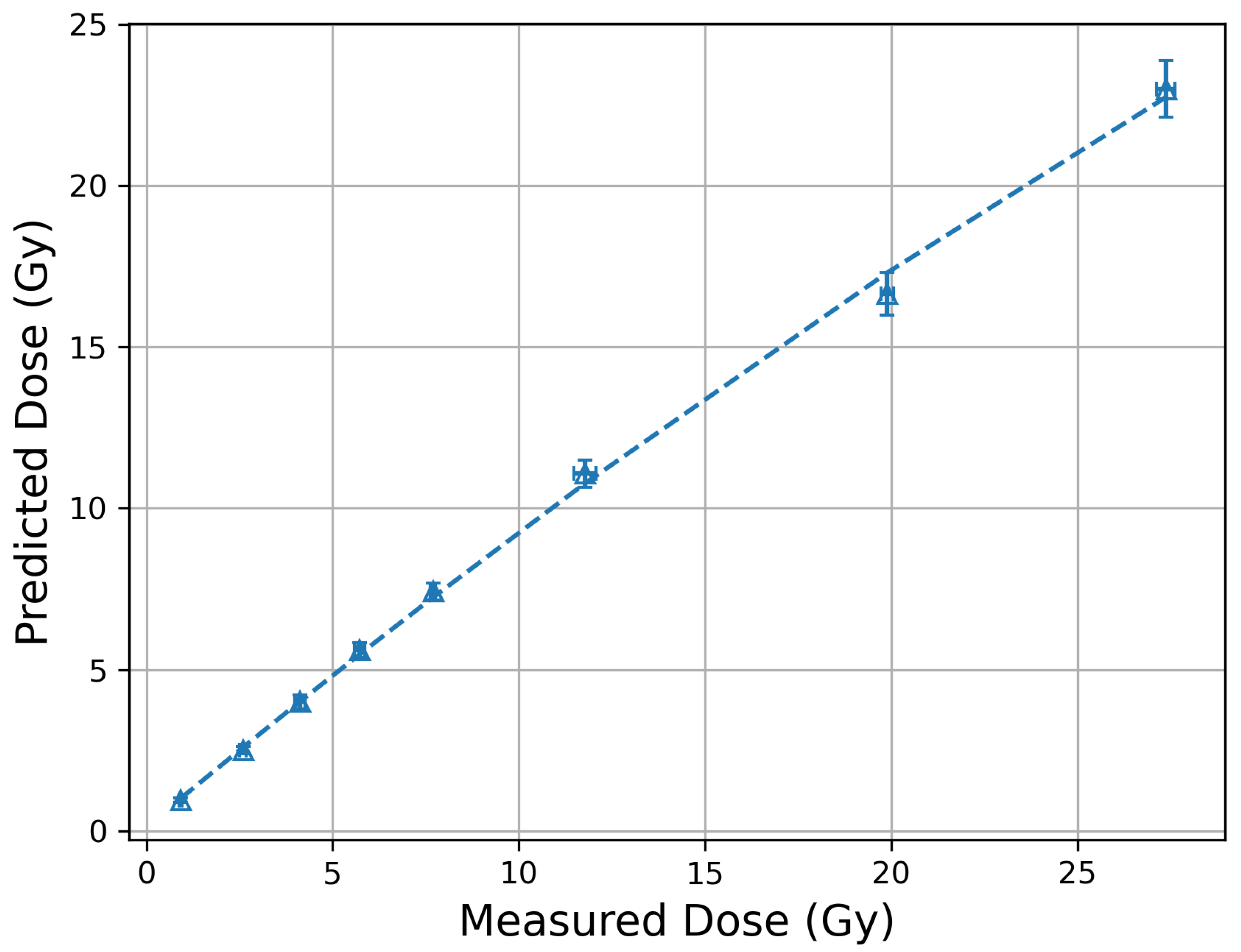
3.2. MOSkin Linearity and Track Spacing

With corrected film measurements, the MOSkin exhibits a linear response to total absorbed dose with increasing DPP, as well as large doses delivered within a single pulse. Shown in Figure 7, the slope of the fitted line, 3.386 ± 0.022 mV/cGy, corresponds to the sensitivity of the MOSkins within the 100 MeV electron irradiation environment at PEER. This is in the vicinity of other results in the literature when the incident field is electrons in the MeV range [41,45]. The magnitude is higher; however, the MOSkins used in this study have a thicker gate oxide than those of other studies. The MOSkin sensitivity is proportional to the square of the gate oxide thickness and applying this factor to the results of this study places the sensitivity in the expected range. To confirm the MOSkin response is valid, the sensitivity was also checked in a 20 MeV electron field using a Varian Truebeam linac at St. George Hospital in Sydney, Australia. The temporal structure of the linac pulses are orders of magnitude different from that of PEER and are summarised in Table 1. The results of the calibration are also seen in Figure 7. The slope of the linear fit is 3.761 ± 0.003 mV/cGy, an increase in sensitivity of about 11%, within the expectations relative to PEER.
The highest single pulse delivery was 22.73 Gy, consisting of 100 bunches, at an instantaneous dose rate within a bunch of 2.273 × 10 9 Gy/s, and average dose rate of 1.14 × 10 8 Gy/s. A single bunch is delivered in 100 ps, and hence, we consider the DPB for comparison against the Geminate model, as this is the shortest structure of the PEER beam. At 0.23 Gy/bunch, well below the limiting case for the Geminate model, the spacing between the incident tracks calculated using Equation (3) is 385 nm. At a factor of 24 greater than 16 nm, the required separation for 100 MeV electrons, it can be assumed that the overlap of electrons between neighbouring tracks has not invalidated the application of the Geminate model. Therefore, the absorbed dose remains proportional to the number of incident tracks, and the linear response of the MOSkin to increasing DPP is, therefore, as expected.

4. Discussion

The film sensitivity was unchanged between IMBL and ARPANSA, confirming its energy independence and allowing for the future use of on-site facilities for film calibration requirements at PEER. However, the results presented in this paper demonstrate that the DPP and dose-rate dependence of EBT-XD at UHDR must be checked and accounted for if they are to be used for reference dosimetry. With a stable beam and accurate charge diagnostics, this dependence can be corrected for, allowing for reference dose measurements at depth within a phantom, something that a charge measurement cannot truly provide in isolation. The normalised response of the film to a 20 pulse delivery corresponds to the clinical average dose rates that it was designed for, and the range of responses agree well with the Geant4 simulations, confirming that the corrected film provides a true representation of the absorbed dose. While other forms of reference dosimetry exist, such as calorimetry, they also require corrections and may not be immediately suitable for a small, diverging Gaussian beam. Hence, in the absence of suitable reference dosimetry, EBT-XD provides a reference measurement that may not be easily attainable through other available means. The use of EBT-XD with correction factors will, much like dose calibration curves, require evaluation of their ongoing suitability, due to time-based darkening, as well as intra-batch variation. It is not expected that the correction curve will hold over time and across batches. Though this effect was not known prior to the experiment, further reviews of the available literature uncovered a similar observation with the use of UHDR protons and EBT-XD at 7500 Gy/s [69], and recently, a thorough investigation within UHDR electron fields [70]. This work extended the range of DPP and dose rates within which EBT-XD was evaluated. Together, these works confirm that the observed dependence may not be confined to a single batch. It should be restated for clarity, however, that the use of EBT-XD within these novel fields is orders of magnitude outside of the manufacturer’s intended use. In hindsight, the existence of a dependence should be rather unsurprising.
Comparing the MOSkin response to the total absorbed dose revealed a linear response as expected; the Geminate model allows for this expectation. The MOSkin threshold voltage is measured before and after exposure to radiation, and the change in threshold voltage is essentially a measure of radiation damage. A simple explanation, therefore, is that in the absence of e-h pair overlap, the level of radiation damage is not proportional to the duration of radiation exposure, only to the total dose. The linearity of the device over its lifetime was also demonstrated, with consecutive irradiations and build up of dose, as well as single-pulse irradiations adhering to the same linear trend line with a slope of 3.386 ± 0.022 mV/cGy, representing the sensitivity of the device to the 100 MeV electron field. When the sensitivity was determined in a clinical 20 MeV field, an increase of 11.1% was found relative to the 100 MeV measurements. As the pair spacing along the track is larger for 20 MeV electrons, recombination is expected to be lower, and therefore an increase in sensitivity is expected. The ratio of stopping powers (and e-h pair spacing along a track) predicted an approximately 8% increase in sensitivity would occur. To model the exact value of such an increase requires significant further investigation, including the effect of perturbations of the MOSkin electric field due to the moving charges of different energies. Such work is beyond the scope of this paper. However, a difference of only 3% between the observed and predicted change in sensitivity is considered very minor, and the results are certainly within the expectations, considering a difference of 80 MeV between the two electron energies investigated, and the non-uniform fluence distribution of the PEER electron beam.
Track spacing calculations shown in Equation (3) were used to estimate the track spacing during these experiments, as well as the dose required to induce DPP dependence in the MOSkin. The calculations provided in this study consider the dose delivered within a single bunch, as it is the shortest structure of the PEER beam, at 100 ps in length. However, the initial recombination is said to occur over timescales as low as 10 ps or less. The assumption is made that all of the charge is delivered in the transverse plane to facilitate these calculations. At 100 ps, of course this cannot be true in reality. This leads to the suggestion that the MOSkin can actually experience a higher DPB than the estimated 133 Gy while retaining DPP independence. However, the calculations produce an average track spacing, by considering a homogeneous distribution of incident tracks and infinite dose rate. The track structure could be investigated further with the use of Monte Carlo simulations, but the possibility that a track directly follows the existing path of another cannot be completely ignored. Hole transport in MOS devices is in the order of seconds, so it could be assumed that delivering large total doses over extremely small timescales may actually reduce this phenomena, compared to clinical deliveries occurring over minutes. While the Geminate model assumes that sufficient separation renders e-h pairs isolated, of course, some charge overlap may occur prior to the required separation of 16 nm used in the calculations; these values are calculated based upon assumptions and simplifications that are unlikely to truly represent the physical system. To increase the dose high enough to test these predictions will require ultra-short bunches and likely the use of focused beams to achieve the orders-of-magnitude-higher dose required.
Table 1 shows the typical parameters defining the pulse structure of Varian Truebeam accelerators as well as PEER. It is clearly evident that these are vastly different irradiation fields. This, as well as the large changes in energy between clinical and VHEE regimes, has created the challenge for dosimetry and diagnostics within UHDR VHEE investigations. Many advances have been made toward devices capable of characterising these beams, with great success. However, no existing device suitable for UHDR VHEE dosimetry is also utilised clinically. The MOSkin has proven to be the first device capable of providing accurate measurements for quality assurance within both clinical X-ray/electron, and UHDR VHEE environments, with no changes to either the detector or the readout system. This is a substantial leap toward meeting the critical requirements for eventual pre-clinical, and clinical trials of VHEE radiotherapy.

5. Conclusions

EBT-XD is a commonly used dosimetry film in UHDR investigations, and within this study it was shown to exhibit a dependence upon DPP, becoming pronounced above 4 Gy. While the film was not designed to be used at either the energies, or the dose rates used within this study and other VHEE studies, with careful consideration and properly applied correction factors, it still provides an adequate response suitable for such measurements. By using it as an independent reference measurement, the MOSkin was able to be investigated for DPP independence, having previously been shown to exhibit a response independent of dose rate in both clinical and UHDR environments. When subjected to increasing DPP at PEER, the linearity of the MOSkin response was retained, demonstrating its applicability for dose measurements within UHDR VHEE fields. While this linearity is a significant result in and of itself, the MOSkin is the only device that is currently utilised clinically, whilst also being suitable for on-patient quality assurance dosimetry as the field of VHEE radiotherapy progresses towards animal and human trials.

Author Contributions

Conceptualisation, J.C., M.L. and A.R.; Data curation, J.C. and E.E.; Formal analysis, J.C. and M.L.; Funding acquisition, Y.-R.E.T. and M.L.; Investigation, J.C., E.E., T.C., P.B., M.C., J.P. (Joel Poder), D.B. and Y.-R.E.T.; Methodology, J.C., E.E., J.P. (Jason Paino) and Y.-R.E.T.; Project administration, J.C. and Y.-R.E.T.; Resources, J.P. (Joel Poder), D.H., D.B., D.C., M.P. and Y.-R.E.T.; Software, P.B. and Y.-R.E.T.; Supervision, D.C., M.P., A.R., Y.-R.E.T. and M.L.; Validation, J.C.; Writing—original draft, J.C.; Writing—review and editing, J.C., E.E., T.C., P.B., M.C., J.P. (Joel Poder), D.H., J.P. (Jason Paino), D.B., D.C., M.P., A.R., Y.-R.E.T. and M.L. All authors have read and agreed to the published version of the manuscript.

Funding

J.C. receives Australian Government RTP scholarship APP505948 and was supported by an AINSE Ltd. Postgraduate Research Award (PGRA).

Institutional Review Board Statement

Not applicable.

Informed Consent Statement

Not applicable.

Data Availability Statement

The raw data supporting the conclusions of this article will be made available by the authors on request.

Acknowledgments

This research was undertaken on the PEER and IMBL beamlines, Australian Synchrotron, part of ANSTO. The authors would like to thank Craig Davis from the Faculty of Information and Engineering Sciences, University of Wollongong for his significant contributions towards manufacturing of experimental apparatus.

Conflicts of Interest

M.L., A.R., M.P., and D.C. declare consulting with Electrogenics Laboratories Ltd., which is commercializing the MOSkin detector. Electrogenics Laboratories Ltd. had no role in the design of the study, in the collection, analyses, or interpretation of data, in the writing of the manuscript, or in the decision to publish the results.

Abbreviations

The following abbreviations are used in this manuscript:
UHDRUltra-high dose rate
VHEEVery-high-energy electrons
PEERPulsed Energetic Electrons for Research
DPPDose per pulse
MOSFETMetal oxide semiconductor field-effect transistor
CMRPCentre for Medical Radiation Physics
CTFast current transformer
Δ V Shift in threshold voltage
PMMAPolymethyl methacrylate
DPBDose per bunch
FCFaraday cup
FCTFast current transformer
PRFPulse repetition frequency

References

  1. Dewey, D.L.; Boag, J.W. Modification of the Oxygen Effect when Bacteria are given Large Pulses of Radiation. Nature 1959, 183, 1450–1451. [Google Scholar] [CrossRef] [PubMed]
  2. Field, S.; Bewley, D. Effects of Dose-rate on the Radiation Response of Rat Skin. Int. J. Radiat. Biol. Relat. Stud. Phys. Chem. Med. 1974, 26, 259–267. [Google Scholar] [CrossRef] [PubMed]
  3. Hendry, J.H.; Moore, J.V.; Hodgson, B.W.; Keene, J.P. The Constant Low Oxygen Concentration in All the Target Cells for Mouse Tail Radionecrosis. Radiat. Res. 1982, 92, 172–181. [Google Scholar] [CrossRef] [PubMed]
  4. Hornsey, S.; Alper, T. Unexpected Dose-rate Effect in the Killing of Mice by Radiation. Nature 1966, 210, 212–213. [Google Scholar] [CrossRef] [PubMed]
  5. Favaudon, V.; Caplier, L.; Monceau, V.; Pouzoulet, F.; Sayarath, M.; Fouillade, C.; Poupon, M.F.; Brito, I.; Hupé, P.; Bourhis, J.; et al. Ultrahigh dose-rate FLASH irradiation increases the differential response between normal and tumor tissue in mice. Sci. Transl. Med. 2014, 6, 245ra93. [Google Scholar] [CrossRef] [PubMed]
  6. Bourhis, J.; Montay-Gruel, P.; Gonçalves Jorge, P.; Bailat, C.; Petit, B.; Ollivier, J.; Jeanneret-Sozzi, W.; Ozsahin, M.; Bochud, F.; Moeckli, R.; et al. Clinical translation of FLASH radiotherapy: Why and how? Radiother. Oncol. 2019, 139, 11–17. [Google Scholar] [CrossRef] [PubMed]
  7. Montay-Gruel, P.; Acharya, M.M.; Gonçalves Jorge, P.; Petit, B.; Petridis, I.G.; Fuchs, P.; Leavitt, R.; Petersson, K.; Gondré, M.; Ollivier, J.; et al. Hypofractionated FLASH-RT as an Effective Treatment against Glioblastoma that Reduces Neurocognitive Side Effects in Mice. Clin. Cancer Res. 2021, 27, 775–784. [Google Scholar] [CrossRef] [PubMed]
  8. Chabi, S.; To, T.H.V.; Leavitt, R.; Poglio, S.; Jorge, P.G.; Jaccard, M.; Petersson, K.; Petit, B.; Roméo, P.H.; Pflumio, F.; et al. Ultra-high-dose-rate FLASH and Conventional-Dose-Rate Irradiation Differentially Affect Human Acute Lymphoblastic Leukemia and Normal Hematopoiesis. Int. J. Radiat. Oncol. 2021, 109, 819–829. [Google Scholar] [CrossRef] [PubMed]
  9. Simmons, D.A.; Lartey, F.M.; Schüler, E.; Rafat, M.; King, G.; Kim, A.; Ko, R.; Semaan, S.; Gonzalez, S.; Jenkins, M.; et al. Reduced cognitive deficits after FLASH irradiation of whole mouse brain are associated with less hippocampal dendritic spine loss and neuroinflammation. FLASH Radiother. Int. Workshop 2019, 139, 4–10. [Google Scholar] [CrossRef] [PubMed]
  10. Vozenin, M.C.; De Fornel, P.; Petersson, K.; Favaudon, V.; Jaccard, M.; Germond, J.F.; Petit, B.; Burki, M.; Ferrand, G.; Patin, D.; et al. The Advantage of FLASH Radiotherapy Confirmed in Mini-pig and Cat-cancer Patients. Clin. Cancer Res. 2019, 25, 35–42. [Google Scholar] [CrossRef] [PubMed]
  11. Montay-Gruel, P.; Corde, S.; Laissue, J.A.; Bazalova-Carter, M. FLASH radiotherapy with photon beams. Med. Phys. 2022, 49, 2055–2067. [Google Scholar] [CrossRef] [PubMed]
  12. Schüler, E.; Acharya, M.; Montay-Gruel, P.; Loo, B.W., Jr.; Vozenin, M.C.; Maxim, P.G. Ultra-high dose rate electron beams and the FLASH effect: From preclinical evidence to a new radiotherapy paradigm. Med. Phys. 2022, 49, 2082–2095. [Google Scholar] [CrossRef] [PubMed]
  13. Atkinson, J.; Bezak, E.; Le, H.; Kempson, I. The current status of FLASH particle therapy: A systematic review. Phys. Eng. Sci. Med. 2023, 46, 529–560. [Google Scholar] [CrossRef] [PubMed]
  14. Lin, B.; Gao, F.; Yang, Y.; Wu, D.; Zhang, Y.; Feng, G.; Dai, T.; Du, X. FLASH Radiotherapy: History and Future. Front. Oncol. 2021, 11, 644400. [Google Scholar] [CrossRef] [PubMed]
  15. DesRosiers, C.; Moskvin, V.; Bielajew, A.F.; Papiez, L. 150–250 MeV Electron Beams in Radiation Therapy. Phys. Med. Biol. 2000, 45, 1781. [Google Scholar] [CrossRef] [PubMed]
  16. Sarti, A.; De Maria, P.; Battistoni, G.; De Simoni, M.; Di Felice, C.; Dong, Y.; Fischetti, M.; Franciosini, G.; Marafini, M.; Marampon, F.; et al. Deep Seated Tumour Treatments With Electrons of High Energy Delivered at FLASH Rates: The Example of Prostate Cancer. Front. Oncol. 2021, 11. [Google Scholar] [CrossRef] [PubMed]
  17. Böhlen, T.T.; Germond, J.F.; Traneus, E.; Bourhis, J.; Vozenin, M.C.; Bailat, C.; Bochud, F.; Moeckli, R. Characteristics of very high-energy electron beams for the irradiation of deep-seated targets. Med. Phys. 2021, 48, 3958–3967. [Google Scholar] [CrossRef] [PubMed]
  18. Ronga, M.G.; Cavallone, M.; Patriarca, A.; Leite, A.M.; Loap, P.; Favaudon, V.; Créhange, G.; De Marzi, L. Back to the Future: Very High-Energy Electrons (VHEEs) and Their Potential Application in Radiation Therapy. Cancers 2021, 13, 4942. [Google Scholar] [CrossRef] [PubMed]
  19. Bazalova-Carter, M.; Qu, B.; Palma, B.; Hårdemark, B.; Hynning, E.; Jensen, C.; Maxim, P.G.; Loo Jr., B.W. Treatment planning for radiotherapy with very high-energy electron beams and comparison of VHEE and VMAT plans. Med. Phys. 2015, 42, 2615–2625. [Google Scholar] [CrossRef] [PubMed]
  20. Fischer, J.; Whitmore, L.; Desrosiers, C.; Sheehy, S.; Bazalova-Carter, M. Very high-energy electrons as radiotherapy opportunity. Eur. Phys. J. Plus 2024, 139, 728. [Google Scholar] [CrossRef]
  21. Corsini, R.; Aksoy, A.; Farabolini, W.; Gilardi, A.; Malyzhenkov, A.; Bateman, J.; Dosanjh, M.; Korysko, P.; Robertson, C.; Rieker, V. Medical activites in CLEAR: Studies towards radiotherapy using very high energy electrons (VHEE) in the FLSH regime. In Proceedings of the LINAC2024, Chicago, IL, USA, 25–30 August 2024; pp. 674–677. [Google Scholar] [CrossRef]
  22. Burkart, F.; Aßmann, R.; Dinter, H.; Jaster-Merz, S.; Kuropka, W.; Mayet, F.; Vinatier, T. The ARES Linac at DESY. In Proceedings of the 31st International Linear Accelerator Conference, LINAC2022, Liverpool, UK, 28 August–2 September 2022. [Google Scholar] [CrossRef]
  23. Subiel, A.; Moskvin, V.; Welsh, G.H.; Cipiccia, S.; Reboredo, D.; Evans, P.; Partridge, M.; DesRosiers, C.; Anania, M.P.; Cianchi, A.; et al. Dosimetry of Very High Energy Electrons (VHEE) for Radiotherapy Applications: Using Radiochromic Film Measurements and Monte Carlo Simulations. Phys. Med. Biol. 2014, 59, 5811. [Google Scholar] [CrossRef] [PubMed]
  24. Bazalova-Carter, M.; Liu, M.; Palma, B.; Dunning, M.; McCormick, D.; Hemsing, E.; Nelson, J.; Jobe, K.; Colby, E.; Koong, A.C.; et al. Comparison of Film Measurements and Monte Carlo Simulations of Dose Delivered with Very High-Energy Electron Beams in a Polystyrene Phantom. Med. Phys. 2015, 42, 1606–1613. [Google Scholar] [CrossRef] [PubMed]
  25. Butler, D.J.; Barnes, M.; McEwen, M.R.; Lerch, M.L.F.; Sheehy, S.L.; Tan, Y.R.E.; Williams, I.M.; Yap, J.S.L. Dosimetry for FLASH and other non-standard radiotherapy sources. Radiat. Meas. 2025, 180, 107330. [Google Scholar] [CrossRef]
  26. Gonçalves Jorge, P.; Grilj, V.; Bourhis, J.; Vozenin, M.C.; Germond, J.F.; Bochud, F.; Bailat, C.; Moeckli, R. Technical note: Validation of an ultrahigh dose rate pulsed electron beam monitoring system using a current transformer for FLASH preclinical studies. Med. Phys. 2022, 49, 1831–1838. [Google Scholar] [CrossRef] [PubMed]
  27. Jain, S.; Cetnar, A.; Woollard, J.; Gupta, N.; Blakaj, D.; Chakravarti, A.; Ayan, A.S. Pulse parameter optimizer: An efficient tool for achieving prescribed dose and dose rate with electron FLASH platforms. Phys. Med. Biol. 2023, 68. [Google Scholar] [CrossRef] [PubMed]
  28. Cayley, J.; Paino, J.; Guatelli, S.; Rosenfeld, A.; Lerch, M.; Tan, Y.R.E. Simulation and commissioning of a Faraday cup for absolute charge measurements of very high-energy electrons in-air at PEER. Front. Phys. 2024, 12. [Google Scholar] [CrossRef]
  29. Vozenin, M.C.; Montay-Gruel, P.; Limoli, C.; Germond, J.F. All Irradiations that are Ultra-High Dose Rate may not be FLASH: The Critical Importance of Beam Parameter Characterization and In Vivo Validation of the FLASH Effect. Radiat. Res. 2020, 194, 571–572. [Google Scholar] [CrossRef] [PubMed]
  30. Bateman, J.J.; Buchanan, E.; Corsini, R.; Farabolini, W.; Korysko, P.; Garbrecht Larsen, R.; Malyzhenkov, A.; Ortega Ruiz, I.; Rieker, V.; Gerbershagen, A.; et al. Development of a novel fibre optic beam profile and dose monitor for very high energy electron radiotherapy at ultrahigh dose rates. Phys. Med. Biol. 2024, 69, 085006. [Google Scholar] [CrossRef] [PubMed]
  31. Clements, N.; Esplen, N.; Bateman, J.; Robertson, C.; Dosanjh, M.; Korysko, P.; Farabolini, W.; Corsini, R.; Bazalova-Carter, M. Mini-GRID radiotherapy on the CLEAR very-high-energy electron beamline: Collimator optimization, film dosimetry, and Monte Carlo simulations. Phys. Med. Biol. 2024, 69. [Google Scholar] [CrossRef] [PubMed]
  32. Ashraf, M.R.; Melemenidis, S.; Liu, K.; Grilj, V.; Jansen, J.; Velasquez, B.; Connell, L.; Schulz, J.B.; Bailat, C.; Libed, A.; et al. Multi-Institutional Audit of FLASH and Conventional Dosimetry With a 3D Printed Anatomically Realistic Mouse Phantom. Int. J. Radiat. Oncol. 2024, 120, 287–300. [Google Scholar] [CrossRef] [PubMed]
  33. Almeida, A.; Togno, M.; Ballesteros-Zebadua, P.; Franco-Perez, J.; Geyer, R.; Schaefer, R.; Petit, B.; Grilj, V.; Meer, D.; Safai, S.; et al. Dosimetric and biologic intercomparison between electron and proton FLASH beams. Radiother. Oncol. J. Eur. Soc. Ther. Radiol. Oncol. 2024, 190, 109953. [Google Scholar] [CrossRef] [PubMed]
  34. Kranzer, R.; Schüller, A.; Bourgouin, A.; Hackel, T.; Poppinga, D.; Lapp, M.; Looe, H.K.; Poppe, B. Response of diamond detectors in ultra-high dose-per-pulse electron beams for dosimetry at FLASH radiotherapy. Phys. Med. Biol. 2022, 67, 075002. [Google Scholar] [CrossRef] [PubMed]
  35. Gómez, F.; Gonzalez-Castaño, D.M.; Fernández, N.G.; Pardo-Montero, J.; Schüller, A.; Gasparini, A.; Vanreusel, V.; Verellen, D.; Felici, G.; Kranzer, R.; et al. Development of an ultra-thin parallel plate ionization chamber for dosimetry in FLASH radiotherapy. Med. Phys. 2022, 49, 4705–4714. [Google Scholar] [CrossRef] [PubMed]
  36. Di Martino, F.; Barca, P.; Barone, S.; Bortoli, E.; Borgheresi, R.; De Stefano, S.; Di Francesco, M.; Faillace, L.; Giuliano, L.; Grasso, L.; et al. FLASH Radiotherapy With Electrons: Issues Related to the Production, Monitoring, and Dosimetric Characterization of the Beam. Front. Phys. 2020, 8. [Google Scholar] [CrossRef]
  37. Di Martino, F.; Giannelli, M.; Traino, A.C.; Lazzeri, M. Ion recombination correction for very high dose-per-pulse high-energy electron beams. Med. Phys. 2005, 32, 2204–2210. [Google Scholar] [CrossRef] [PubMed]
  38. Fleetwood, D.; Winokur, P.; Schwank, J. Using laboratory X-ray and cobalt-60 irradiations to predict CMOS device response in strategic and space environments. IEEE Trans. Nucl. Sci. 1988, 35, 1497–1505. [Google Scholar] [CrossRef]
  39. Su, F.Y.; Biasi, G.; Tran, L.T.; Pan, V.; Hill, D.; Lielkajis, M.; Cutajar, D.; Petasecca, M.; Lerch, M.; Pastuovic, Z.; et al. Characterization of MOSFET Dosimeters for Alpha Particle Therapy. IEEE Trans. Nucl. Sci. 2022, 69, 925–931. [Google Scholar] [CrossRef]
  40. Alnawaf, H.; Butson, M.; Yu, P.K.N. Measurement and effects of MOSKIN detectors on skin dose during high energy radiotherapy treatment. Australas. Phys. Eng. Sci. Med. 2012, 35, 321–328. [Google Scholar] [CrossRef] [PubMed]
  41. Choi, J.H.; Cutajar, D.; Metcalfe, P.; Downes, S. Application of MOSkin detector for in vivo dosimetry on total skin electron therapy (TSET). Biomed. Phys. Eng. Express 2018, 4, 024002. [Google Scholar] [CrossRef]
  42. Jong, W.; Ung, N.; Tiong, A.; Rosenfeld, A.; Wong, J. Characterisation of a MOSFET-based detector for dose measurement under megavoltage electron beam radiotherapy. Radiat. Phys. Chem. 2018, 144, 76–84. [Google Scholar] [CrossRef]
  43. Jong, W.L.; Wong, J.; Ung, N.M.; Kh, N.; Ho, G.; Cutajar, D.; Rosenfeld, A. Characterization of MOSkin detector for in vivo skin dose measurement during megavoltage radiotherapy. J. Appl. Clin. Med. Phys. Am. Coll. Med. Phys. 2014, 15, 4869. [Google Scholar] [CrossRef] [PubMed]
  44. Kwan, I.; Rosenfeld, A.; Qi, Z.; Wilkinson, D.; Lerch, M.; Cutajar, D.; Safavi-Naeni, M.; Butson, M.; Bucci, J.; Chin, Y.; et al. Skin dosimetry with new MOSFET detectors. Radiat. Meas. 2008, 43, 929–932. [Google Scholar] [CrossRef]
  45. Patterson, E.; Stokes, P.; Cutajar, D.; Rosenfeld, A.; Baines, J.; Metcalfe, P.; Powers, M. High-resolution entry and exit surface dosimetry in a 1.5 T MR-linac. Phys. Eng. Sci. Med. 2023, 46, 787–800. [Google Scholar] [CrossRef] [PubMed]
  46. Tai, M.; Patterson, E.; Metcalfe, P.E.; Rosenfeld, A.; Oborn, B.M. Skin Dose Modeling and Measurement in a High Field In-Line MRI-Linac System. Front. Phys. 2022, 10. [Google Scholar] [CrossRef]
  47. Thorpe, N.K.; Cutajar, D.; Lian, C.; Pitney, M.; Friedman, D.; Perevertaylo, V.; Rosenfeld, A. A comparison of entrance skin dose delivered by clinical angiographic c-arms using the real-time dosimeter: The MOSkin. Australas. Phys. Eng. Sci. Med. 2016, 39, 423–430. [Google Scholar] [CrossRef] [PubMed]
  48. Lian, C.P.L.; Othman, M.A.R.; Cutajar, D.; Butson, M.; Guatelli, S.; Rosenfeld, A.B. Monte Carlo study of the energy response and depth dose water equivalence of the MOSkin radiation dosimeter at clinical kilovoltage photon energies. Australas. Phys. Eng. Sci. Med. 2011, 34, 273–279. [Google Scholar] [CrossRef] [PubMed]
  49. Patterson, E.; Powers, M.; Metcalfe, P.E.; Cutajar, D.; Oborn, B.M.; Baines, J.A. Electron streaming dose measurements and calculations on a 1.5 T MR-Linac. J. Appl. Clin. Med. Phys. 2024, 25, e14370. [Google Scholar] [CrossRef] [PubMed]
  50. Valentin, J. Basic anatomical and physiological data for use in radiological protection: Reference values: ICRP Publication 89. Ann. ICRP 2002, 32, 1–277. [Google Scholar] [CrossRef]
  51. Council Directive 2013/59/Euratom of 5 December 2013 Laying Down Basic Safety Standards for Protection Against the Dangers Arising from Exposure to Ionising Radiation, and Repealing Directives 89/618/Euratom, 90/641/Euratom, 96/29/Euratom, 97/43/Euratom and 2003/122/Euratom. 2013. Available online: http://data.europa.eu/eli/dir/2013/59/oj/eng (accessed on 3 February 2025).
  52. Safari, M.J.; Wong, J.H.D.; Ng, K.H.; Jong, W.L.; Cutajar, D.L.; Rosenfeld, A.B. Characterization of a MOSkin detector for in vivo skin dose measurements during interventional radiology procedures. Med. Phys. 2015, 42, 2550–2559. [Google Scholar] [CrossRef] [PubMed]
  53. Carrara, M.; Romanyukha, A.; Tenconi, C.; Mazzeo, D.; Cerrotta, A.; Borroni, M.; Cutajar, D.; Petasecca, M.; Lerch, M.; Bucci, J.; et al. Clinical application of MOSkin dosimeters to rectal wall in vivo dosimetry in gynecological HDR brachytherapy. Phys. Medica 2017, 41, 5–12. [Google Scholar] [CrossRef] [PubMed]
  54. Legge, K.; Cutajar, D.; Wilfert, A.; Martin, J.; Rozenfeld, A.; O’Connor, D.J.; Greer, P. SU-F-T-328: Real-Time in Vivo Dosimetry of Prostate SBRT Boost Treatments Using MOSkin Detectors. Med. Phys. 2016, 43, 3538. [Google Scholar] [CrossRef]
  55. Poder, J.; Howie, A.; Brown, R.; Bucci, J.; Rosenfeld, A.; Enari, K.; Schreiber, K.; Carrara, M.; Bece, A.; Malouf, D.; et al. Towards real time in-vivo rectal dosimetry during trans-rectal ultrasound based high dose rate prostate brachytherapy using MOSkin dosimeters. Radiother. Oncol. 2020, 151, 273–279. [Google Scholar] [CrossRef] [PubMed]
  56. Jong, W.; Ung, N.; Wong, J.; Ng, K.; Wan Ishak, W.; Abdul Malik, R.; Phua, V.; Cutajar, D.; Metcalfe, P.; Rosenfeld, A.; et al. In vivo skin dose measurement using MOSkin detectors in tangential breast radiotherapy. Phys. Medica 2016, 32, 1466–1474. [Google Scholar] [CrossRef] [PubMed]
  57. Souris, J.S.; Cheng, S.H.; Pelizzari, C.; Chen, N.T.; La Riviere, P.; Chen, C.T.; Lo, L.W. Radioluminescence characterization of in situ x-ray nanodosimeters: Potential real-time monitors and modulators of external beam radiation therapy. Appl. Phys. Lett. 2014, 105, 203110. [Google Scholar] [CrossRef] [PubMed]
  58. Cayley, J.; Tan, Y.R.E.; Petasecca, M.; Cutajar, D.; Breslin, T.; Rosenfeld, A.; Lerch, M. MOSkin dosimetry for an ultra-high dose-rate, very high-energy electron irradiation environment at PEER. Front. Phys. 2024, 12. [Google Scholar] [CrossRef]
  59. Smyth, L.; Alves, A.; Collins, K.; Beveridge, S. Gafchromic EBT3 Film Provides Equivalent Dosimetric Performance to EBT-XD Film for Stereotactic Radiosurgery Dosimetry. Phys. Eng. Sci. Med. 2024, 47, 1095–1106. [Google Scholar] [CrossRef] [PubMed]
  60. Szpala, S.; Huang, V.; Zhao, Y.; Kyle, A.; Minchinton, A.; Karan, T.; Kohli, K. Dosimetry with a clinical linac adapted to FLASH electron beams. J. Appl. Clin. Med. Phys. 2021, 22, 50–59. [Google Scholar] [CrossRef] [PubMed]
  61. Ashland. Ashland EBT-XD Datasheet. Available online: https://www.ashland.com/file_source/Ashland/Documents/PHA21-011_Gafchromic%20EBT-XD%20Protocol.pdf (accessed on 12 May 2024).
  62. Wanstall, H.C.; Korysko, P.; Farabolini, W.; Corsini, R.; Bateman, J.J.; Rieker, V.; Hemming, A.; Henthorn, N.T.; Merchant, M.J.; Santina, E.; et al. VHEE FLASH sparing effect measured at CLEAR, CERN with DNA damage of pBR322 plasmid as a biological endpoint. Sci. Rep. 2024, 14, 14803. [Google Scholar] [CrossRef] [PubMed]
  63. Whitmore, L.; Mackay, R.I.; van Herk, M.; Korysko, P.; Farabolini, W.; Malyzhenkov, A.; Corsini, R.; Jones, R.M. CERN-based experiments and Monte-Carlo studies on focused dose delivery with very high energy electron (VHEE) beams for radiotherapy applications. Sci. Rep. 2024, 14, 11120. [Google Scholar] [CrossRef] [PubMed]
  64. Lagzda, A.; Angal-Kalinin, D.; Jones, J.; Aitkenhead, A.; Kirkby, K.J.; MacKay, R.; Van Herk, M.; Farabolini, W.; Zeeshan, S.; Jones, R.M. Influence of heterogeneous media on Very High Energy Electron (VHEE) dose penetration and a Monte Carlo-based comparison with existing radiotherapy modalities. Nucl. Instruments Methods Phys. Res. Sect. B Beam Interact. Mater. Atoms 2020, 482, 70–81. [Google Scholar] [CrossRef]
  65. Small, K.L.; Henthorn, N.T.; Angal-Kalinin, D.; Chadwick, A.L.; Santina, E.; Aitkenhead, A.; Kirkby, K.J.; Smith, R.J.; Surman, M.; Jones, J.; et al. Evaluating very high energy electron RBE from nanodosimetric pBR322 plasmid DNA damage. Sci. Rep. 2021, 11, 3341. [Google Scholar] [CrossRef] [PubMed]
  66. Verona Rinati, G.; Felici, G.; Galante, F.; Gasparini, A.; Kranzer, R.; Mariani, G.; Pacitti, M.; Prestopino, G.; Schüller, A.; Vanreusel, V.; et al. Application of a Novel Diamond Detector for Commissioning of FLASH Radiotherapy Electron Beams. Med. Phys. 2022, 49, 5513–5522. [Google Scholar] [CrossRef] [PubMed]
  67. Bourgouin, A.; Schüller, A.; Hackel, T.; Kranzer, R.; Poppinga, D.; Kapsch, R.P.; McEwen, M. Calorimeter for Real-Time Dosimetry of Pulsed Ultra-High Dose Rate Electron Beams. Front. Phys. 2020, 8. [Google Scholar] [CrossRef]
  68. Medina, E.; Ferro, A.; Abujami, M.; Camperi, A.; Centis Vignali, M.; Data, E.; Del Sarto, D.; Deut, U.; Di Martino, F.; Fadavi Mazinani, M.; et al. First Experimental Validation of Silicon-Based Sensors for Monitoring Ultra-High Dose Rate Electron Beams. Front. Phys. 2024, 12. [Google Scholar] [CrossRef]
  69. Villoing, D.; Koumeir, C.; Bongrand, A.; Guertin, A.; Haddad, F.; Métivier, V.; Poirier, F.; Potiron, V.; Servagent, N.; Supiot, S.; et al. Technical note: Proton beam dosimetry at ultra-high dose rates (FLASH): Evaluation of GAFchromic™ (EBT3, EBT-XD) and OrthoChromic (OC-1) film performances. Med. Phys. 2022, 49, 2732–2745. [Google Scholar] [CrossRef] [PubMed]
  70. Del Sarto, D.; Masturzo, L.; Cavalieri, A.; Celentano, M.; Fuentes, T.; Gadducci, G.; Giannini, N.; Gonnelli, A.; Milluzzo, G.; Paiar, F.; et al. A systematic investigation on the response of EBT-XD gafchromic films to varying dose-per-pulse, average dose-rate and instantaneous dose-rate in electron flash beams. Front. Phys. 2025, 13. [Google Scholar] [CrossRef]
  71. Oldham, T.R. Ionizing Radiation Effects in MOS Oxides; International Series on Advances in Solid State Electronics and Technology; World Scientific: Singapore, 2000. [Google Scholar] [CrossRef]
  72. Oldham, T.R. Basic Mechanisms of TID and DDD Response in MOS and Bipolar Microelectronics; NASA: Washington, DC, USA, 2012.
  73. Ma, T.; Dressendorfer, P. Ionizing Radiation Effects in MOS Devices and Circuits; INIS Reference Number: 21087484; John Wiley and Sons Inc.: Hoboken, NJ, USA, 1989. [Google Scholar]
  74. Zilio, V.O.; Joneja, O.P.; Popowski, Y.; Rosenfeld, A.; Chawla, R. Absolute depth-dose-rate measurements for an 192Ir HDR brachytherapy source in water using MOSFET detectors. Med. Phys. 2006, 33, 1532–1539. [Google Scholar] [CrossRef] [PubMed]
  75. Kattner, K. Modelling the effects of heavy charged particles on MOSFETs. Air Force Inst. Technol. 1988. [Google Scholar]
  76. Ausman, G. Field Dependence of Geminate Recombination in a Dielectric Medium; Defense Technical Information Center: Fort Belvoir, VI, USA, 1987. [Google Scholar]
  77. Wojcik, M.; Tachiya, M. Geminate charge recombination with distance-dependent intrinsic reaction rate: Escape probability and its electric field effect. Radiat. Phys. Chem. 2005, 74, 132–138. [Google Scholar] [CrossRef]
  78. Tachiya, M. Breakdown of the Onsager theory of geminate ion recombination. J. Chem. Phys. 1988, 89, 6929–6935. [Google Scholar] [CrossRef]
  79. The International Commission on Radiation Units and Measurements (ICRU). Stopping Powers for Electrons and Positrons; Technical Report 0-913394-31-9—ICRU–37 INIS Reference Number: 24031395; ICRU: Bethesda, MA, USA, 1984. [Google Scholar]
  80. Bichsel, H. Stopping Power of Fast Charged Particles in Heavy Elements; National Institute of Standards and Technology: Gaithersburg, MD, USA, 1991.
  81. NIST. NIST E-Star Database. Available online: https://physics.nist.gov/PhysRefData/Star/Text/ESTAR.html (accessed on 27 June 2024).
  82. Hughes, R.C. High field electronic properties of SiO2. Solid-State Electron. 1978, 21, 251–258. [Google Scholar] [CrossRef]
  83. Brown, D.B.; Dozier, C.M. Electron-Hole Recombination in Irradiated SiO2 from a Microdosimetry Viewpoint. IEEE Trans. Nucl. Sci. 1981, 28, 4142–4144. [Google Scholar] [CrossRef]
  84. Murat, M.; Akkerman, A.; Barak, J. Spatial distribution of electron-hole pairs induced by electrons and protons in SiO/sub 2/. IEEE Trans. Nucl. Sci. 2004, 51, 3211–3218. [Google Scholar] [CrossRef]
  85. Chan, M.F.; Park, J.; Aydin, R.; Lim, S.B. Technical note: Energy dependence of the Gafchromic EBT4 film: Dose-response curves for 70 kV, 6 MV, 6 MV FFF, 10 MV FFF, and 15 MV x-ray beams. Med. Phys. 2023, 50, 3738–3745. [Google Scholar] [CrossRef] [PubMed]
  86. Massillon-Jl, G.; Chiu-Tsao, S.T.; Muñoz, I. Energy Dependence of the New Gafchromic EBT3 Film: Dose Response Curves for 50 kV, 6 and 15 MV X-Ray Beams. Int. J. Med. Physics, Clin. Eng. Radiat. Oncol. 2012, 1, 60–65. [Google Scholar] [CrossRef]
  87. Arce, P.; Bolst, D.; Bordage, M.C.; Brown, J.M.C.; Cirrone, P.; Cortés-Giraldo, M.A.; Cutajar, D.; Cuttone, G.; Desorgher, L.; Dondero, P.; et al. Report on G4-Med, a Geant4 benchmarking system for medical physics applications developed by the Geant4 Medical Simulation Benchmarking Group. Med. Phys. 2021, 48, 19–56. [Google Scholar] [CrossRef] [PubMed]
  88. Agostinelli, S.; Allison, J.; Amako, K.; Apostolakis, J.; Araujo, H.; Arce, P.; Asai, M.; Axen, D.; Banerjee, S.; Barrand, G.; et al. Geant4—a simulation toolkit. Nucl. Instruments Methods Phys. Res. Sect. A Accel. Spectrometers Detect. Assoc. Equip. 2003, 506, 250–303. [Google Scholar] [CrossRef]
  89. Filipev, I.; Alnaghy, S.; Carolan, M.; Paino, J.; Petasecca, M.; Cutajar, D.; Poder, J.; Davies, J.B.; Oborn, B.M.; Hardcastle, N.; et al. High Spatial Resolution Dosimetry for Radiation Oncology with “MagicPlates”, a New 976-pixel Monolithic Silicon Detector. J. Appl. Clin. Med. Phys. 2025, 26, e70015. [Google Scholar] [CrossRef] [PubMed]
Figure 1. The applicability of the Geminate recombination model rests upon a critical assumption of large separation distances between electron–hole pairs. Top: When the centre-to-centre spacing is greater than twice the length of r, initial recombination can be considered restricted to a single pair. Bottom: The limiting case, whereby increased initial recombination will occur due to decreased separation distances between neighbouring electron–hole pairs.
Applsci 15 08101 g001
Figure 2. Top left and top right: The PMMA phantom holding unexposed EBT-XD film with a scintillator attached for beam alignment, as well as three MOSkins. Also displayed is the post-irradiation grid of nine film exposures, which allows the assessment of transverse beam stability. Clear separation of the exposures is evident. Bottom: Imaging of the scintillator to align targets with the centre of the PEER beam. The central axis of the scintillation spot is marked and locked in thesoftware, then the targets are moved into the centre of the field and irradiated. The scale markers on the scintillator are in millimetres.
Applsci 15 08101 g002
Figure 3. The EBT-XD film calibration curves performed at the Imaging and Medical Beamline of the ANSTO Australian Synchrotron, adjacent to PEER, as well as at the Australian Radiation Protection and Nuclear Safety Agency. The presence of energy dependence impacting upon calibrations, as reported in the literature for other types of dosimetry film, is not evident for EBT-XD used in this investigation. Uncertainty is within markers.
Applsci 15 08101 g003
Figure 4. A super-linear response of the EBT-XD relative to charge measurements was observed, prompting the investigation of potential DPP or dose-rate dependence within the UHDR field at PEER. The data plotted in red is a linear series scaled to the first data point ratio of Gy/pC. The maximum deviation observed is for the highest charge measurement, where the reported dose from EBT-XD film is 20% higher than expected.
Applsci 15 08101 g004
Figure 5. To investigate the presence of DPP or dose-rate effects, EBT-XD film was exposed to three levels of charge, each delivered over three sets of temporal structures; a single pulse as used during the rest of this paper, 2 pulses, to halve the DPP and halve the average dose rate, and 20 pulses, to reduce the DPP by a factor of 20 and create dose rates of less than 1 Gy/s. Due to the non-standard operation of the linac, the charge delivery was not as stable as during the normal, single-pulse operation that PEER is optimised for (though this can be improved for future work). The baseline of the film exhibited some uneven darkening, giving rise to larger than usual uncertainties, shown as one standard error of the mean. However, the dependence upon DPP is evident, especially for single and two pulse deliveries. The trend against average dose rate is much clearer, and the normalised response for all levels of charge converges for the twenty-pulse delivery, confirming the presence of a large dose-rate dependence within the UHDR used in this study.
Applsci 15 08101 g005
Figure 6. The correction curve established for the EBT-XD film. The mean normalised response of the 20 pulse deliveries, 0.003997 Gy/pC shown in Figure 5, was used to calculate the predicted dose for the measured charge during each film exposure.
Applsci 15 08101 g006
Figure 7. The MOSkin exhibited a linear response across all levels of DPP, whether accumulated during increasing levels of dose, or through large, single pulses. The slope of the linear fit, representing the sensitivity of the MOSkin within the PEER field is 3.386 ± 0.022 mV/cGy. Ratios of electron–hole pair spacing between 20 MeV and 100 MeV fields predicted an 8% increase in sensitivity. The sensitivity of the MOSkin within the 20 MeV clinical field is 3.761 ± 0.003 mV/cGy, approximately 11.1%. All MOSkin uncertainties are one standard deviation. The dose uncertainty for the VHEE exposure propagates with the correction curves and is applied to the standard deviation of raw film measurements. Clinical dose deliveries are highly regulated, uncertainties are 1% of the prescribed dose.
Applsci 15 08101 g007
Table 1. Comparison of typical Varian Truebeam pulse structures and dose rates against PEER. Clinical values adapted from [89]. The DPP stated for PEER reflects the values used in this investigation. It is envisioned however, that an increase of at least twice is feasible in the current configuration with varied delivery parameters.
Varian TruebeamPEER
Bunch LengthUnknown100 ps
Pulse Length3–5 μ s 20–400 ns
DPP 10 3 Gy1–23 Gy
Max Average Dose rates 10 1 Gy/s 10 8 Gy/s
Disclaimer/Publisher’s Note: The statements, opinions and data contained in all publications are solely those of the individual author(s) and contributor(s) and not of MDPI and/or the editor(s). MDPI and/or the editor(s) disclaim responsibility for any injury to people or property resulting from any ideas, methods, instructions or products referred to in the content.

