Article

A Hierarchically Structured Ni-NOF@ZIF-L Heterojunction Using Van Der Waals Interactions for Electrocatalytic Reduction of CO2 to HCOOH

School of Chemistry and Chemical Engineering, Anhui University of Technology, Maanshan 243002, China
*
Author to whom correspondence should be addressed.
Appl. Sci. 2025, 15(14), 8095; https://doi.org/10.3390/app15148095
Submission received: 19 May 2025 / Revised: 18 June 2025 / Accepted: 22 June 2025 / Published: 21 July 2025

Abstract

The electrocatalytic CO2 reduction reaction (CO2RR) offers an energy-saving and environmentally friendly approach to producing hydrocarbon fuels. The use of a gas diffusion electrode (GDE) flow cell has generally improved the rate of CO2RR, while the gas diffusion layer (GDL) remains a significant challenge. In this study, we successfully engineered a novel metal–organic framework (MOF) heterojunction through the controlled coating of zeolitic imidazolate framework (ZIF-L) on ultrathin nickel—metal–organic framework (Ni-MOF) nanosheets. This innovative architecture simultaneously integrates GDL functionality and exposes abundant solid–liquid–gas triple-phase boundaries. The resulting Ni-MOF@ZIF-L heterostructure demonstrates exceptional performance, achieving a formate Faradaic efficiency of 92.4% while suppressing the hydrogen evolution reaction (HER) to 6.7%. Through computational modeling of the optimized heterojunction configuration, we further elucidated its competitive adsorption behavior and electronic modulation effects. The experimental and theoretical results demonstrate an improvement in electrochemical CO2 reduction activity with suppressed hydrogen evolution for the heterojunction because of its hydrophobic interface, good electron transfer capability, and high CO2 adsorption at the catalyst interface. This work provides a new insight into the rational design of porous crystalline materials in electrocatalytic CO2RR.

1. Introduction

Since the Industrial Revolution, fossil fuels have underpinned global energy infrastructure. Due to excessive reliance on these fossil fuels, atmospheric CO2 concentrations have risen dramatically, making them a key driver of global warming [1,2,3,4,5]. Consequently, the fixation and conversion of CO2 into high-value hydrocarbon fuels represent a promising strategy to address both energy sustainability and climate change. Recently, the electrocatalytic CO2RR has garnered significant interest owing to its environmentally benign process and efficient conversion into value-added products, including gaseous species (e.g., carbon monoxide, methane) and liquid fuels (e.g., formic acid, ethanol, methanol) [6,7,8,9,10]. However, the extremely low CO2-to-H2O molar ratio (~1:1300 at 1 atm) in aqueous electrolytes, coupled with the slow diffusion kinetics of CO2, severely limits the reaction activity. To overcome these mass transport constraints, flow cell systems incorporating gas diffusion electrodes (GDEs) have been widely adopted, enabling high-rate CO2 electrolysis [11,12]. A typical GDE comprises three layers: a porous carbon fiber paper (CFP), a microporous layer (MPL), and a catalyst layer. This architecture facilitates gaseous CO2 transport while restricting liquid permeation [13,14,15]. Nevertheless, weak interfacial contact between the MPL and catalyst often compromises electrical conductivity and long-term stability. Moreover, liquid flooding of the pores obstructs CO2 access to active sites and prolongs diffusion pathways, ultimately deactivating the GDE during CO2RR. Thus, designing GDEs with high efficiency, selectivity, and durability remains a critical yet formidable challenge in electrocatalytic CO2RR.
Metal–organic frameworks (MOFs) have demonstrated distinctive advantages in the electrochemical CO2 reduction reaction (CO2RR) owing to their tunable pore structures and abundant metal active sites. The porous architecture of these materials enables efficient CO2 adsorption and enrichment, while their metal nodes serve as active centers to facilitate the reaction process, thereby significantly enhancing the local CO2 concentration around catalytic sites [16,17,18,19]. For instance, the In-BDC MOF developed by Shu’s team achieved a formate Faradaic efficiency of 88% at a potential of −0.669 V [20]. In another study, Yang’s group employed a microwave-assisted method to rapidly construct bimetallic Bi-M MOFs (M = Zn/Sn/In), among which the BiZn-MOF exhibited a remarkable formate Faradaic efficiency of 92% at −0.9 V (vs. RHE) while maintaining a stable current density for 13 h of continuous electrolysis [21]. Nevertheless, current MOF-based catalysts still face critical challenges, including insufficient electron conductivity and competitive hydrogen evolution reaction (HER), resulting in ineffective activation of adsorbed CO2 and consequently limiting the overall catalytic performance [22,23,24,25].
This study proposes a novel strategy for fabricating GDEs with tailored properties by integrating two or more distinct MOFs into a sophisticated MOF hybrid material. Specifically, Ni-MOF (CCDC-638866, from the Cambridge Crystallographic Data Centre) [26] was selected as the catalytic substrate due to its high-density nickel active sites, exceptional electron conductivity, and moderate redox potential [27,28,29,30,31], which collectively ensure efficient electron transfer while selectively promoting CO2 reduction over the competing HER. Concurrently, ZIF materials demonstrate outstanding performance in suppressing HER owing to their inherent chemical stability, tunable hydrophobicity, and superior CO2 adsorption capacity [12,32,33,34,35,36,37]. A representative example is the work by Li’s team, where precisely engineered ZIF-8 with 3.4 Å molecular sieve channels achieved selective exclusion of 2.8 Å water molecules, thereby dramatically reducing the HER Faradaic efficiency from 30% to 8% [38].
Building upon this foundation, we innovatively constructed a MOF-on-MOF heterostructure by coating ZIF-L {Zn(mim)2·(Hmim)1/2·(H2O)3/2, Hmim = 2-methylimidazole} onto Ni-MOF {Ni2(OH)2(BDC), BDC = 1,4-benzenedicarboxylate} (Figure 1), which capitalizes on the synergistic effects between the two materials: Ni-MOF provides active sites and conductive pathways, while ZIF-L enhances CO2 adsorption and utilizes its hydrophobic properties to suppress HER. The resulting heterostructure achieved a remarkable formate Faradaic efficiency of 92.4% while suppressing the HER to 6.7%, surpassing existing systems in both selectivity and stability. Density functional theory (DFT) calculations revealed intense interfacial electron transfer within the heterojunction, which effectively promotes CO2 adsorption and activation. This discovery provides crucial theoretical insights for advancing CO2RR technologies through MOF heterostructure engineering.

2. Materials and Methods

2.1. Synthesis of Samples

Preparation of Ni-MOF arrays: A homogeneous green solution was first prepared by dissolving 2.24 mmol (372 mg) of terephthalic acid (Aladdin, Shanghai, China) and 1.39 mmol (330 mg) of NiCl2·6H2O (Aladdin) in 32 mL of N,N-dimethylformamide (DMF) (Aladdin) under continuous stirring. To this solution, 2 mL of deionized water and 2 mL of ethanol (Aladdin) were added, followed by thorough mixing to ensure uniformity. The resulting mixture was then transferred into a Teflon-lined autoclave, into which a carbon paper (CP) (Macklin, Shanghai, China) substrate was immersed to facilitate the growth of the nanorod arrays. The autoclave was sealed and heated in an oven at 120 °C for 12 h. After the reaction, the system was allowed to cool naturally to room temperature. The product was collected and repeatedly washed with DMF and ethanol to remove residual organic species. Finally, the obtained green powder was dried at 60 °C for 1 h, yielding well-defined Ni-MOF arrays.
Preparation of Ni-MOF@ZIF-L arrays: A ZIF-L suspension was first prepared by separately dissolving 11.76 mmol (0.966 g) of 2-methylimidazole (Aladdin) and 1.24 mmol (0.36 g) of Zn(NO3)2·6H2O (Aladdin) in 50 mL of deionized water each, followed by thorough mixing of the two solutions. The as-synthesized Ni-MOF was then immersed into the ZIF-L suspension and allowed to react at room temperature for 24 h under continuous stirring. After completion of the reaction, the resulting light green product was collected and washed repeatedly with deionized water and ethanol to remove unreacted species and impurities. Finally, the purified sample was dried under vacuum at 60 °C for 1 h to obtain the Ni-MOF@ZIF-L composite material.

2.2. Materials Characterization

The scanning electron microscopy (SEM) images were acquired using a JSM-6700F (JEOL, Akishima, Tokyo, Japan) field-emission system at an accelerating voltage of 10 kV. Transmission electron microscopy (TEM) characterization was performed on an HF-3300 microscope (Hitachi High-Technologies Corp., Chiyoda, Tokyo, Japan) equipped with an energy-dispersive X-ray spectroscopy (EDS) system operating at 200 kV. The crystallographic properties of the catalysts were examined using a Bruker D8 Advanced X-ray powder diffractometer (Bruker, MA, USA and Karlsruhe, Germany,) with Cu Kα radiation (λ = 0.15418 nm) at 40 kV and 40 mA. The surface chemical states were analyzed by X-ray photoelectron spectroscopy (XPS) measurements conducted on a Thermo Scientific ESCALAB 250Xi (Thermo Fisher Scientific, East Grinstead, West Sussex, UK) system with Al Kα radiation (hv = 1486.6 eV). The X-ray absorption spectroscopy measurements at the Ni/Co K-edges were performed on beamline BL14W1 at the Shanghai Synchrotron Radiation Facility (SSRF, 3.5 GeV storage ring), Shanghai Advanced Research Institute, Chinese Academy of Sciences, Shanghai, China, where both ex situ X-ray absorption near-edge structure (XANES) spectra and extended X-ray absorption fine structure (EXAFS) spectra were collected for the Ni-MOF/ZIF-L material and its corresponding heterojunction.
All calculations were performed using spin-polarized density functional theory (DFT) within the projector augmented wave (PAW) method, as implemented in the Vienna Ab Initio Simulation Package (VASP). The wave functions of valence electrons (Ni: 3d84s2, Co: 3d74s2, O: 2s22p4, S: 3s23p4) were expanded using a plane-wave basis set with a kinetic energy cutoff of 450 eV. The exchange–correlation interactions were treated by the generalized gradient approximation (GGA) with the Perdew–Burke–Ernzerhof (PBE) functional. Structural relaxations were performed until reaching convergence criteria of 10−4 eV for total energy and 0.02 eV/Å for Hellmann–Feynman forces. A 3 × 3 × 1 Gamma-centered Monkhorst-Pack k-point mesh was used for Brillouin-zone integration during geometry optimizations. Atomic charges were analyzed using the Bader charge partitioning scheme [39].

2.3. Electrochemical Measurements

All electrochemical measurements were conducted at room temperature using an H-type electrolytic cell. The cathode and anode compartments were separated by a proton exchange membrane. The volumes of 0.5 M KHCO3 electrolyte in both the cathode and anode compartments were measured separately. A three-electrode system was employed, with a platinum sheet as the counter electrode, an Ag/AgCl (saturated KCl) reference electrode, and catalyst-coated carbon paper as the working electrode. Subsequently, all three electrodes were maintained at the same height. During the electrochemical tests, a constant CO2 supply was maintained by continuous purging at a flow rate of 10 sccm, with the CO2-saturated electrolyte exhibiting a pH of 7.2. The calculation formulas are as follows:
E R H E = E A g / A g c l + 0.059 × P H + 0.210
Electrochemical impedance spectroscopy (EIS) was recorded at open-circuit potentials over a frequency range of 105 Hz to 10−2 Hz.

2.4. Product Analysis

The gaseous products were directly analyzed by gas chromatography (GC7900) after exiting the gas outlet of the H-type electrolytic cell, while the liquid products were characterized using high-performance liquid chromatography (HPLC, EClassical3200). The Faradaic efficiency (FE) of gaseous products was calculated as follows:
F E = ν × C × N × F 60 × 24,500 × I × 100 %
where ν represents the supplied CO2 gas flow rate(10 sccm), C is the gaseous product relative concentration measured by GC, N(2) is the number of electrons transferred to form one-mol carbon monoxide (CO) or hydrogen (H2), F stands for Faraday efficiency (96,485 C mol−1), and I is current.
F E = n f o r m a t e × N × F I × t × 100 %
where nformate is the amount of formate, N(2) is the number of electrons transferred to form one mol formate, F stands for Faraday efficiency (96,485 C mol−1), I is the current, and t stands for reaction time (120 min). The partial current density of formate is obtained by multiplying the total current density with their corresponding FE.

3. Results and Discussion

It was found that Ni atoms are octahedrally coordinated by six O atoms, and the resulting pseudo-octahedra are interconnected to form a metal layer. The adjacent Ni layers are separated by terephthalic acids, with an interlayer distance of 3.5 Å on the (200) facet. Meanwhile, Co adopts a regular [CoN4] tetrahedral geometry to form ZIF-L, which contains a large zero-dimensional pore (cavity) well-suited for accommodating CO2 molecules. Powder X-ray diffraction (PXRD) analysis (scan range: 5–70°, step size: 5°/min) confirms that the pure Ni-MOF nanoarray shares an identical crystalline structure with the previously reported monoclinic Ni2(OH)2BDC MOF [40] As shown in Figure 2a, the four diffraction peaks can be indexed to the (200) and (001) crystallographic planes. After growing ZIF-L onto Ni-MOF, additional peaks corresponding to the (112), (220), and (004) lattice planes of ZIF-L appear in the heterojunction, further demonstrating the high crystallinity of both Ni-MOF and ZIF-L [41]. TEM images reveal that the Ni-MOF nanoarray is grown vertically on carbon paper, with a thickness of ~10 nm and a diameter of ~1.2 μm (not mm). As shown in Figure 2b, rod-like ZIF-L with a diameter of ~50 nm is grown on the Ni-MOF surface, forming the Ni-MOF@ZIF-L heterojunction. The ZIF-L grows preferentially along the (001) direction on the (200) plane of Ni-MOF, consistent with the XRD results. The hierarchical structure, composed of sheet-like Ni-MOF and rod-like ZIF-L, is clearly visible in the TEM image (Figure 2c). High-resolution TEM further reveals distinct lattice fringes corresponding to the Ni-MOF (001) plane and the ZIF-L (004) plane, with a sharp interface between them [42,43]. Elemental mapping analysis shows homogeneous distributions of Ni and O in the Ni-MOF core and Co and N in the ZIF-L shell, confirming the uniform coating of ZIF-L on the Ni-MOF surface (Figure 2d). Energy-dispersive EDS and inductively coupled plasma optical emission spectrometry (ICP-OES) reveal a Ni:Co atomic ratio of ~3:2, further verifying the successful formation of the Ni-MOF@ZIF-L heterojunction.
The porous structure of the heterojunction was evaluated by N2 adsorption–desorption measurements. As shown in Figure 2e, N2 adsorption–desorption tests indicate that the excellent porous properties of ZIF-L itself (with a BET-specific surface area of 231.5 cm3 g−1) are inherited by the heterojunction (the BET-specific surface area of Ni-MOF@ZIF-L is 185.7 cm3 g−1). The pore-size distributions are predominantly in the range of 2–4 nm (Figure 2d, inset), further confirming the hierarchically micro- and mesoporous structure of the heterojunction, which provides ample storage spaces and active contact sites for CO2. The soft cushion-type cavities in the ZIF-L shell can adaptively accommodate CO2 molecules, and the strong interactions (such as hydrogen bonds) between 2-methylimidazole ligands and CO2 can “anchor” CO2 to increase its concentration near the catalyst. Meanwhile, the heterojunction interface formed by Ni-MOF and ZIF-L generates a synergistic effect, optimizing active sites and promoting adsorption from multiple dimensions. As shown in Figure 2f, due to the highly dense metal layer structure, Ni-MOF has almost no porosity, resulting in low CO2 adsorption capacity, which significantly limits CO2 adsorption. In contrast, Ni-MOF@ZIF-L achieves more efficient CO2 adsorption and enrichment than Ni-MOF by virtue of its porous structure, shell function, and interfacial synergy. Figure 2g shows a typical photograph of carbon paper and these MOF arrays. It was found that ZIF-L and Ni-MOF@ZIF-L possess hydrophobic properties with external water contact angles of 138.7 and 132.3°, while the hydrophilic Ni-MOF shows a contact angle of only 26.3°. This hydrophobicity slows water diffusion, suppressing the competing hydrogen evolution reaction (HER), while the interconnected porous network ensures rapid CO2 transport to active sites. The hierarchical porosity, combining micropores and mesopores, balances high surface area for CO2 adsorption with efficient mass transfer, promoting enhanced CO2RR activity. The larger mesopores (>2 nm) mitigate diffusion limitations, while the smaller micropores enhance CO2 trapping near catalytic centers. Together, these structural features optimize CO2 enrichment near active sites, accelerate gas diffusion, and inhibit water-induced HER, leading to improved selectivity and reaction kinetics for CO2.
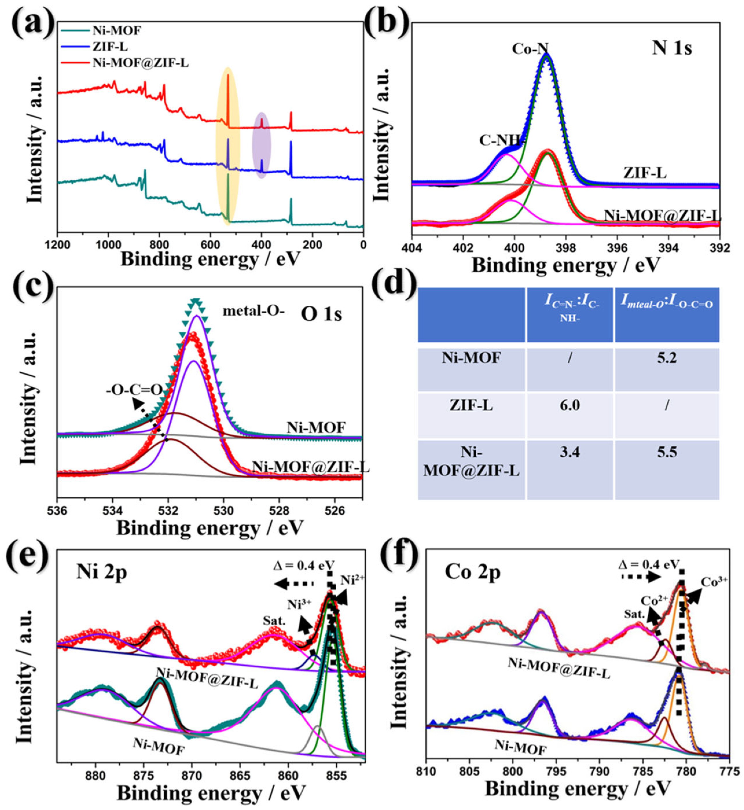
The as-prepared Ni-MOF@ZIF-L heterojunction was further characterized by X-ray photoelectron spectroscopy (XPS) and X-ray absorption spectroscopy (XAS) to probe the electronic interaction between Ni-MOF and ZIF-L. XPS survey and high-resolution spectra (Figure 3a–d) reveal the chemical states of nitrogen and oxygen, as well as their interactions in Ni-MOF, ZIF-L, and Ni-MOF@ZIF-L. In Ni-MOF@ZIF-L, the N 1s binding energy increases due to charge delocalization through Van der Waals interactions with ZIF-L methyl groups, while the IC-N/IC-NH-ratio decreases from 6.0 to 3.4, confirming nitrogen species redistribution. O 1s spectra show the Imenta-O/IO-C=O ratio increases from 5.2 to 5.5 after Ni-MOF compositing, indicating ZIF-L optimizes the oxygen coordination environment. As is shown in Figure 3e, the Ni 2p spectrum exhibits two fitting peaks at 872.3 and 854.4 eV, along with two shakeup satellites at 878.4 and 860.1 eV, being characteristic spin–orbit peaks of Ni2+ [44]. In the Co 2p region, peaks located at 782.8 and 781.5 eV are assigned to Co2+ and Co3+ species (Figure 3f). It is worthy of note the Ni 2p for this heterojunction apparently shifts to higher binding energy compared to pure Ni-MOF. In contrast, the Co 2p peaks for heterojunction are shifted to lower binding energy relative to the corresponding peaks of ZIF-L. Thus, the opposite shifts of ~0.4 eV for Ni and Co suggest the partial electron transfer from Ni to Co in this heterojunction through oxygen bridges between metal ions, leading to an increase in Ni2+ and Co3+.
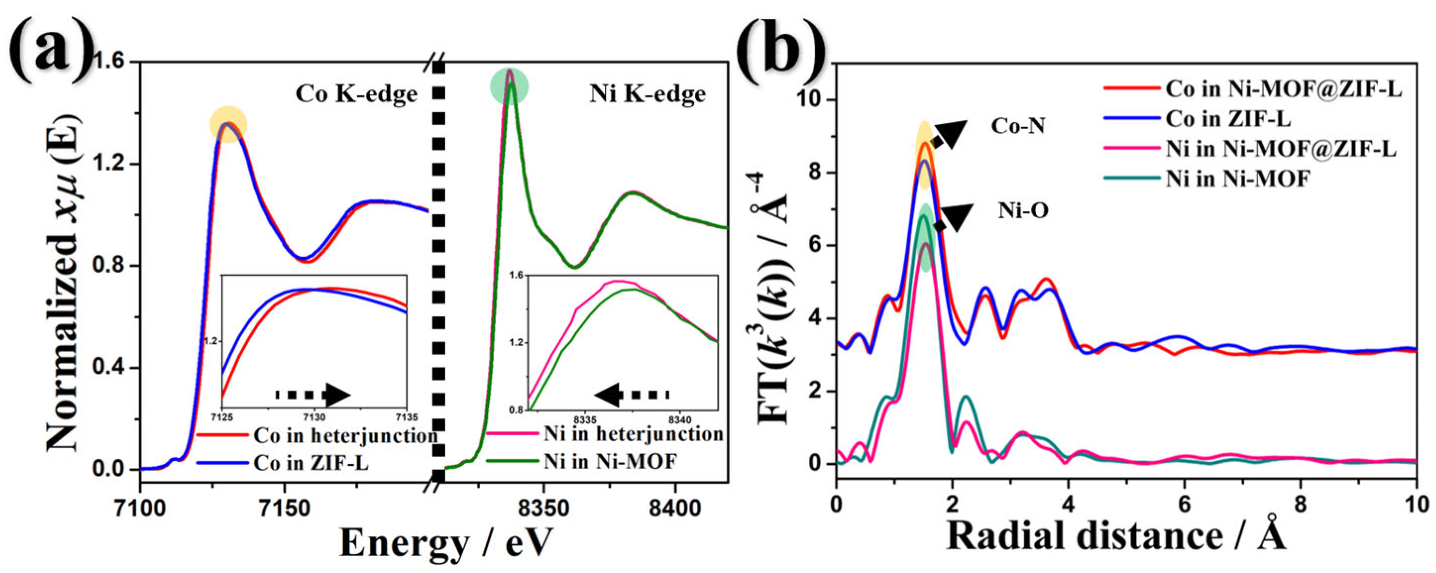
These speculations are further supported by the K-edge XANES spectra of Ni and Co in Figure 4a. Interestingly, compared with pure Ni-MOF and ZIF-L, the K-edge oscillation curves of Ni and Co in this heterojunction show significant differences, indicating the existence of different atomic arrangements. Compared with pure Ni-MOF, the introduced Co can enhance the K-edge peak of Ni, which suggests that there is a partial electron transfer from Ni to Co in this heterojunction. Conversely, compared with ZIF-L, the K-edge peak of Co in the heterojunction shifts to the right (towards the higher energy direction), and its intensity changes. The coordination information of Ni and Co atoms can be confirmed by the Fourier-transform (FT) k3-weighted EXAFS spectra (Figure 4b). Compared with the R-space of Ni in Ni-MOF (about 1.5 Å, Ni–O bond) and Co in ZIF-L (about 1.5 Å, Co–N bond), peaks appear at different positions in this heterojunction. For Ni in the heterojunction, the shift of the peak indicates the shortening of the Ni–O bond; for Co in the heterojunction, the shift of the peak indicates the elongation of the Co–N bond, which reflects the changes in the electron density around Ni and Co atoms. The results of XPS and XAF show that the strong interaction between these 3d metal ions in the heterojunction can synergistically regulate the electronic structure, which is crucial for the high electronic conductivity and activity in the electrocatalytic CO2RR.
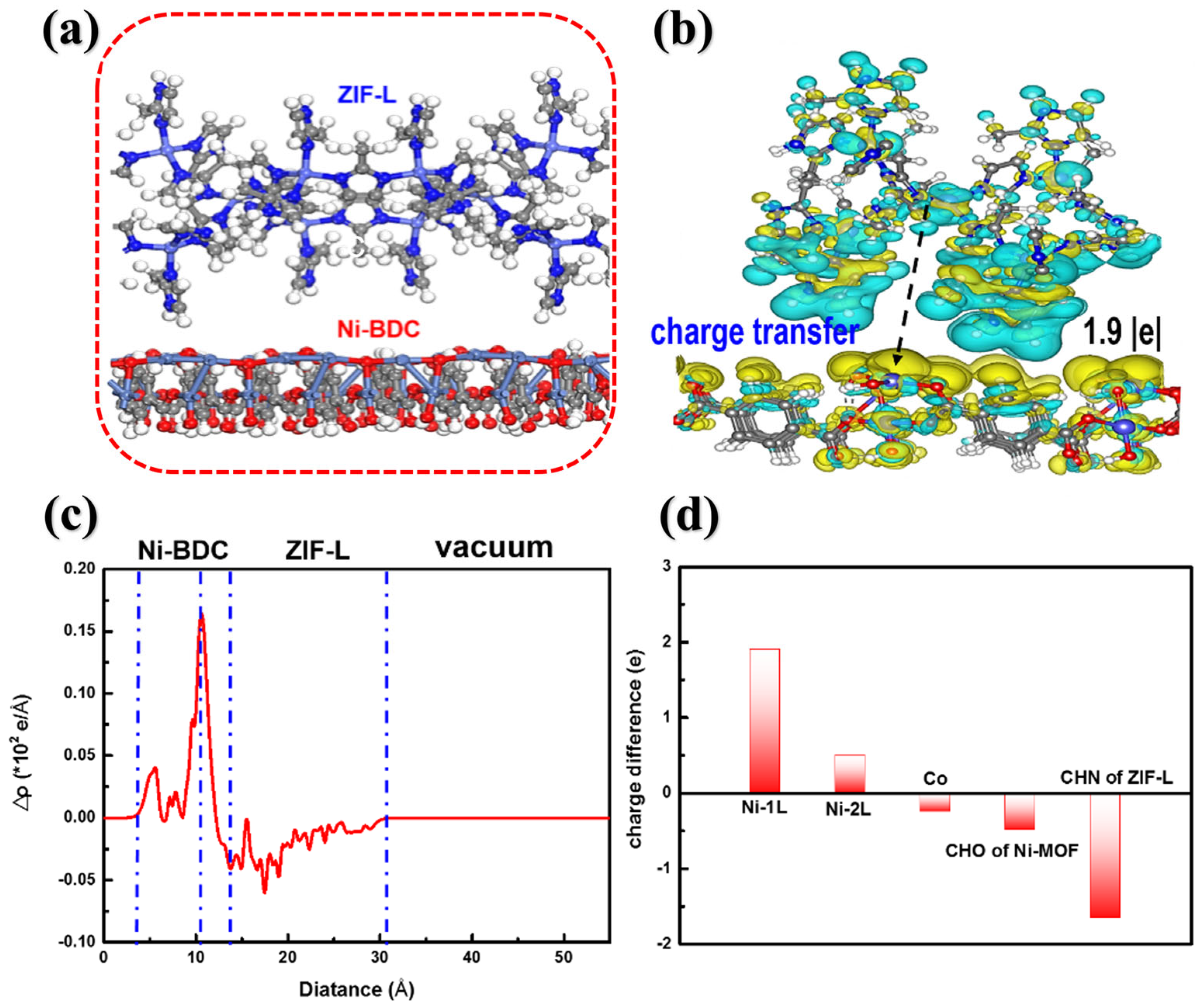
Furthermore, periodic DFT calculations are also carried out to understand the interfacial electronic properties and chemical interactions of the Ni-MOF@ZIF-L heterojunction. Figure 5a shows the optimized heterojunction model structure. At the interface, the imidazole groups of ZIF-L directly interact with the exposed Ni and O atoms of the Ni-MOF surface. The calculated interfacial NH···Ni and NH···O distances are 12.2 Å and 6.9 Å at the PBE level, respectively, indicating no chemical bond formation between ZIF-L and Ni-MOF surfaces. Nevertheless, these two surfaces exhibit strong interaction, with an adsorption energy of 18.4 eV at the PBE level. Electronic structure analysis reveals significant electron transfer at the interface upon heterojunction formation compared to isolated ZIF-L and Ni-MOF surfaces. Charge difference analysis clearly shows approximately 1.9|e| transferred from ZIF-L to Ni-MOF at the interface (evident from blue to yellow regions in Figure 5b). The charge reduction region is mainly located on the imidazole groups of the ZIF-L surface, while the charge accumulation is located on the Ni atoms of the Ni-MOF surface. Figure 5c further shows the plane-averaged charge density difference along the z direction, which is normal to the heterostructure. It is clear that the charge accumulation sharply takes place at the first layer of the Ni-MOF surface, though there is some small contribution at the second layer. In contrast, charge reduction occurs across a broader z-direction region. Further decomposition of the charge difference into the specific atoms reveals more interesting results, as shown in Figure 5d. The charge reduction mainly arises from the C, H, and O atoms of ZIF-L’s imidazole groups, with Co atoms also contributing slightly.
However, the charge accumulation preferentially localizes on the Ni atoms in the first layer of the Ni-MOF surface. These theoretical results are consistent with the XPS and EXAFS experimental data discussed previously. Moreover, we investigated the adsorption energies of CO2 and H2O molecules on this optimized structure to reveal its competitive adsorption capability. The heterojunction shows a markedly enhanced CO2 adsorption energy of 4.22 eV, significantly higher than the 0.34 eV of pure Ni-MOF. Notably, CO2 molecules preferentially adsorb on the ZIF-L side, in agreement with N2 adsorption results, which effectively increases CO2 concentration around the Co-active sites and promotes CO2 activation. Although the H2O adsorption energy on the heterojunction surface also increases substantially (from 1.86 eV to 5.99 eV), hydrogen bonding between H2O and the Ni-MOF surface causes H2O to accumulate predominantly on the Ni-MOF side. These results demonstrate that the heterojunction possesses both strong electron transfer capability and optimized chemical interactions with CO2 and H2O molecules.
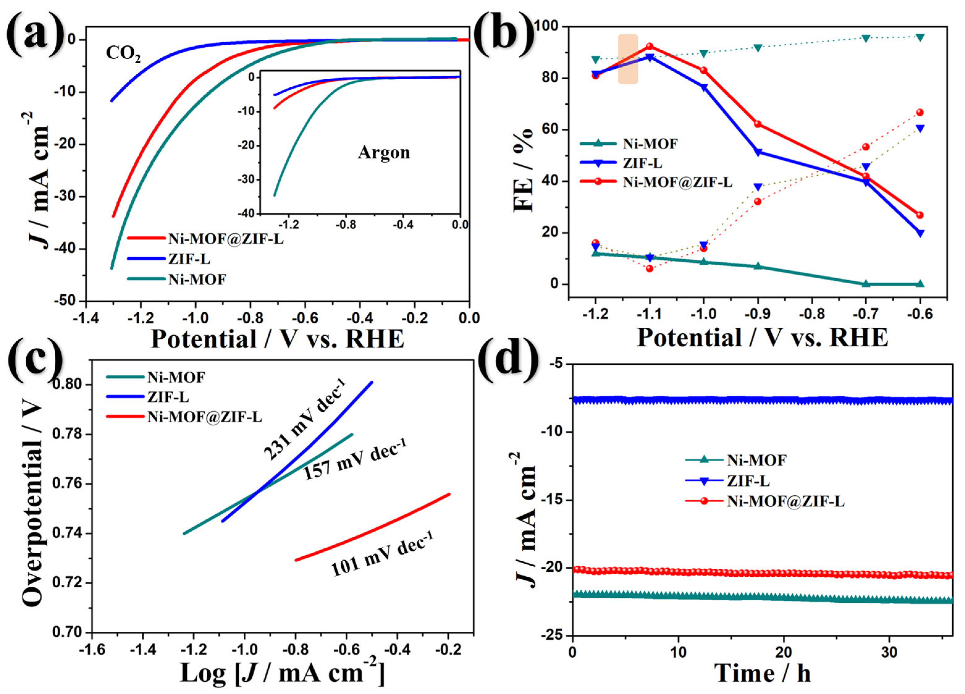
The catalytic performance of the synthesized catalysts was evaluated in a neutral electrolyte using an H-type cell. As shown in Figure 6a, the apparent cathodic currents of these catalysts remain very small in the potential range of 0 to −0.5 V, suggesting negligible CO2RR activity. When the potential shifts negatively beyond −0.6 V, the cathodic current increases with a characteristic hump peak, indicating significant CO2RR activation at sufficiently negative potentials. Notably, Ni-MOF exhibits higher current density in both Ar- and CO2-saturated NaHCO3 at low potentials compared to ZIF-L and the heterojunction, demonstrating its superior HER activity but poor CO2RR performance. Importantly, the Ni-MOF@ZIF-L heterojunction initiates CO2-to-HCOOH conversion at −0.5 V (vs. RHE), a significantly lower onset potential than pure MOFs (Figure 6b). The Faradaic efficiency (FE) of the heterojunction reaches 81.3% for HCOOH at −0.5 V and rapidly increases to 93.9% at −1.1 V, confirming its high activity and selectivity for CO2RR. Competitive HER is effectively suppressed with FEs below 20%, attributable to the material’s hydrophobic properties. The Tafel slope of Ni-MOF@ZIF-L (101 mV dec−1) is substantially lower than those of pure Ni-MOF (157 mV dec−1) and ZIF-L (231 mV dec−1) (Figure 6c), indicating enhanced reaction kinetics for HCOOH production. This improvement likely stems from optimized charge transfer and increased catalytic surface area during CO2RR. Furthermore, the heterojunction maintains stable operation for over 1600 min at 10 mA cm−2 with >90% HCOOH selectivity (Figure 6d), demonstrating exceptional electrocatalytic durability.
To further investigate the effect of the hydrophobicity on the electrocatalytic activity, the SEM and contact angle measurement of Ni-MOF@ZIF-L at different growth times were performed. As shown in Figure 7a, SEM images demonstrated the Ni-MOF can be coated by ZIF-L at different levels, assembling into Ni-MOF@ZIF-L 0.5 h, Ni-MOF@ZIF-L 1 h, and Ni-MOF@ZIF-L 2 h. After 2 h, it was found that ZIF-L completely covered the Ni-MOF, which leads to poor electron transfer capability and hinders the electrocatalytic process (Figure 7c,d). Moreover, the contact angle measurement further illustrates that pure Ni-MOF is hydrophilic, with a deposited water droplet sitting at a contact angle of 22°. After ZIF-L coating, these heterojunctions show significantly enhanced hydrophobicity, with drastically increased contact angles of 88°, 121°, 135°, and 153° (Figure 7b). This falls into the regime of hydrophobicity, where trapped gases are expected at both micro- and nanoscales [45]. The formate and H2 Faradaic efficiencies of pure Ni-MOF are only 23% and 81%, respectively, demonstrating that hydrophilicity restrains CO2RR activity. When Ni-MOF is partially covered by hydrophobic ZIF-L, the formate Faradaic efficiency shows gradual enhancement: Ni-MOF@ZIF-L 0.5 h, Ni-MOF@ZIF-L 1 h, Ni-MOF@ZIF-L 2 h, and Ni-MOF@ZIF-L 4 h exhibit Faradaic efficiencies of 58.6%, 91.9%, 82.7%, and 78.6%, respectively (Figure 7e). A significant decrease in formate Faradaic efficiency is observed for the Ni-MOF@ZIF-L 4 h catalyst, which can be attributed to ZIF-L’s lower conductivity compared to Ni-MOF. The high ZIF-L surface coverage likely compromises electrical conductivity. These results demonstrate that the correlation between ZIF coverage and Faradaic efficiency follows a “volcano curve” due to the competing effects of hydrophobicity and electronic conductivity [46]. Furthermore, investigation of the structure-reactivity relationship reveals that Ni-MOF (Figure 7f), which is initially susceptible to water molecule attack, undergoes surface property modification upon ZIF-L coating. This transformation yields hydrophobic Ni-MOF@ZIF-L, a structure more favorable for CO2 adsorption and reduction reactions.

4. Conclusions

In summary, we have novelly constructed a “MOF on MOF” heterojunction assembled by a conductive Ni-MOF core and a hydrophobic ZIF shell, which exhibits enhanced electrocatalytic CO2RR performance and suppressed HER activity. The XPS and EXAFS data demonstrate that the heterojunction induces strong electronic coupling between Ni-MOF and ZIF-L, facilitating fast kinetics in CO2RR. Furthermore, a volcano-like correlation between the coverage of ZIF-L on Ni-MOF and electrocatalytic performance was observed, attributed to the balance between conductivity, hydrophobicity, and CO2 adsorption. Based on the above results, we have constructed, for the first time, a “MOF on MOF” model structure by investigating the interface structure, adhesion energy, and chemical interactions at the Ni-MOF@ZIF-L interface. Interestingly, the heterojunction shows higher adhesion energy for CO2 and lower adhesion energy for H2O compared with that of pure Ni-MOF. It was found that the electron transfer at the interface is significantly strengthened, which is consistent with the experimental results. Our results thus provide new insights into the rational design of heterojunctions for efficient CO2RR over HER.

Author Contributions

Conceptualization, J.Z.; writing—original draft preparation, L.W.; supervision, X.H. All authors have read and agreed to the published version of the manuscript.

Funding

This work was partly supported by the Outstanding Scientific Research and Innovation Team Program of Higher Education Institutions of Anhui Province (No. 2023AH010015).

Institutional Review Board Statement

Not applicable.

Informed Consent Statement

Not applicable.

Data Availability Statement

The data presented in this study are available upon request from the corresponding author.

Conflicts of Interest

The authors declare no conflicts of interest.

References

  1. Keith, D.W.; Holmes, G.; St Angelo, D.; Heidel, K. Carbon capture and storage: A review. Environ. Sci. Technol. 2021, 55, 7660–7670. [Google Scholar]
  2. Friedlingstein, P.; Jones, M.W.; O’Sullivan, M.; Andrew, R.M.; Bakker, D.C.E.; Hauck, J.; Le Quéré, C.; Peters, G.P.; Peters, W.; Pongratz, J.; et al. Global carbon budget 2021. Nat. Rev. Earth Environ. 2022, 14, 1917–2005. [Google Scholar] [CrossRef]
  3. Santos, A.; Delgado, J.D.; Figueroa, J.D.; Pérez, A. CO2 reduction using Ni-MOF: A comparative study. Chem. Eng. J. 2023, 435, 1397–1412. [Google Scholar]
  4. Kortlever, R.; Shen, J.; Schouten, K.J.P.; Calle-Vallejo, F.; Koper, M.T.M. Electrocatalytic CO2 reduction at metal surfaces. J. Phys. Chem. Lett. 2015, 6, 4073–4082. [Google Scholar] [CrossRef]
  5. Cui, Y.; Cheng, Y.; Yang, C.; Su, Y.; Yao, D.; Liufu, B.; Li, J.; Fang, Y.; Liu, S.; Zhong, Z.; et al. High-performance electrocatalytic CO2 reduction. ACS Sustainable Chem. Eng. 2023, 11, 11229–11238. [Google Scholar] [CrossRef]
  6. Hod, I.; Sampson, M.D.; Deria, P.; Kubiak, C.P.; Farha, O.K.; Hupp, J.T. CO2 electroreduction in MOF-based electrocatalysts. ACS Catal. 2015, 5, 6302–6309. [Google Scholar] [CrossRef]
  7. Zhang, L.; Zhao, Z.J.; Gong, J. CO2 electroreduction: Mechanisms and materials. Angew. Chem. Int. Ed. 2017, 56, 11326–11353. [Google Scholar] [CrossRef]
  8. Xu, Y.; Zhao, Z.J.; Chen, S.; Liu, F.; Zhuang, T.T.; Sun, Q.; Zhang, J.; Chen, W.; Huang, Y.; Li, Y.; et al. Recent advances in CO2 electroreduction. Chem. Soc. Rev. 2021, 50, 2614–2631. [Google Scholar]
  9. Zhang, L.; Wang, J.; Xu, Z.; Liu, H.; Li, Y.; Zhang, J. Recent progress in CO2 reduction electrocatalysts. ACS Energy Lett. 2022, 7, 3225–3236. [Google Scholar]
  10. Wang, Y.; Zhao, L.; Wu, X.; Zhang, X.; Wei, W.; Sun, W. High-performance CO2 reduction catalysts. Catal. Sci. Technol. 2022, 12, 1234–1245. [Google Scholar]
  11. Yang, H.; Wang, X.; Hu, Q.; Chai, X.; Ren, X.; Zhang, Q.; Li, Y.; Liu, Z. New insights into CO2 electroreduction. Small Methods 2020, 4, 1900826. [Google Scholar]
  12. Xu, Z.; Li, H.; Zhang, X.; Liu, Z.; Chen, W. Gas diffusion in catalyst layer for CO2 electroreduction. Nano Res. 2023, 16, 3029–3038. [Google Scholar]
  13. Zhu, H.J.; Lu, M.; Wang, Y.R.; Yao, S.J.; Zhang, M.; Kan, Y.H.; Wang, X.F.; Yan, L.K.; Liu, Q.Y.; Li, S.L.; et al. CO2 electroreduction over metal-based catalysts. Nat. Commun. 2020, 11, 497. [Google Scholar] [CrossRef] [PubMed]
  14. Liu, H.; Chu, J.; Yin, Z.; Cai, X.; Zhuang, L.; Deng, H. Advances in CO2 reduction catalysts. Chem 2018, 4, 1696–1709. [Google Scholar] [CrossRef]
  15. Melchionna, P.; Fornasiero, P.; Finocchio, L.; Maggio, F.; Carboni, M.G.; Bolognese, R.B. CO2 reduction on metal catalysts. ACS Catal. 2022, 12, 5678–5686. [Google Scholar]
  16. Liu, M.; Pang, Y.; Zhang, B.; Luna, P.D.; Voznyy, O.; Xu, J.; Li, Z.H.; Nam, D.; Kim, Y.S.; Xu, T.; et al. CO2 electroreduction on Cu-based catalysts. Nature 2016, 537, 382–388. [Google Scholar] [CrossRef]
  17. Zhang, E.; Wang, T.; Yu, K.; Liu, J.; Chen, W.; Li, A.; Li, J.; Zhuang, X.; Chen, J.G.; Huang, Y.; et al. CO2 electrolysis over Cu-based catalysts. J. Am. Chem. Soc. 2019, 141, 16569–16573. [Google Scholar] [CrossRef]
  18. Feng, D.; Wang, K.; Zhang, Y.; Yang, Y.; Li, Y. Review of CO2 electroreduction: Challenges and opportunities. Chem. Soc. Rev. 2021, 50, 2614–2631. [Google Scholar]
  19. Zhao, Z.J.; Liu, Z.; Zhang, Y.; Ma, S.; Zhang, J. CO2 electroreduction: Catalysis and reaction pathways. Chem. Rev. 2022, 122, 11721–11744. [Google Scholar]
  20. Hou, S.Z.; Zhang, X.D.; Yuan, W.W.; Li, Y.X.; Gu, Z.Y. Indium-based metal–organic framework for high-performance electroreduction of CO2 to formate. Inorg. Chem. 2020, 59, 11298–11304. [Google Scholar] [CrossRef]
  21. Yang, R.; Huang, Q.; Sha, X.; Gao, B.; Peng, J. Regulation of Bimetallic Coordination Centers in MOF Catalyst for Electrochemical CO2 Reduction to Formate. Int. J. Mol. Sci. 2023, 24, 13838. [Google Scholar] [CrossRef] [PubMed]
  22. Liu, Y.; Shen, D.; Zhang, Q.; Lin, Y.; Peng, F. Electrochemical CO2 reduction using Ni-based catalysts. Appl. Catal. B: Environ. 2021, 283, 119630. [Google Scholar]
  23. Xing, Z.; Hu, L.; Ripatti, D.S.; Hu, X.; Feng, X. Bimetallic catalysts for CO2 reduction. Nat. Commun. 2021, 21, 136. [Google Scholar] [CrossRef]
  24. Shi, R.; Guo, J.; Zhang, X.; Waterhouse, G.I.N.; Han, Z.; Zhao, Y.; Shang, L.; Zhou, C.; Jiang, L.; Zhang, T. Efficient wettability-controlled electroreduction of CO2 to CO at Au/C interfaces. Nat. Commun. 2020, 11, 3028. [Google Scholar] [CrossRef]
  25. Pan, F.; Yang, Y. Electrocatalysts for CO2 reduction. Energy Environ. Sci. 2020, 13, 2275–2309. [Google Scholar] [CrossRef]
  26. Carton, A.; Mesbah, A.; Mazet, T.; Porcher, F.; François, M. Ab initio crystal structure of nickel(II) hydroxy-terephthalate by synchrotron powder diffraction and magnetic study. Solid State Sci. 2007, 9, 465–471. [Google Scholar] [CrossRef]
  27. Zhang, L.; Wang, X.; Li, Y. Electrocatalysts for CO2 reduction: Materials and mechanisms. Chem. Commun. 2020, 49, 7379–7421. [Google Scholar]
  28. Wang, X.; Li, Y.; Zhang, L. CO2 electroreduction catalysts and mechanisms. J. Am. Chem. Soc. 2021, 143, 1203–1211. [Google Scholar]
  29. Li, Y.; Zhang, L.; Wang, X. Recent advancements in CO2 electroreduction. ACS Catal. 2022, 12, 3341–3360. [Google Scholar]
  30. Curcio, M.; Vittorio, O.; Cirillo, G.; De Luca, C.; Morandi, M.; Carfagna, A.L.; Curcio, M.; Puoci, F.; Rossi, F. Catalytic CO2 reduction. Molecules. 2021, 26, 4194. [Google Scholar]
  31. Low, J.; Teo, T.Y.K.; Ghosh, S.K.; Cai, J.; Zhang, R.; Wei, W.; Sun, Y.; Yang, Q.; Niu, Z.; Huang, Y.; et al. CO2 electroreduction catalysts. ACS Appl. Mater. Interfaces 2021, 13, 17847–17858. [Google Scholar]
  32. Li, H.; Zhang, Y.; Wang, X.; Zhou, X.; Jiang, X. CO2 electroreduction on Ni-based catalysts. J. Am. Chem. Soc. 2022, 144, 342–349. [Google Scholar]
  33. Xu, J.; Liu, T.; Zhou, Y.; Zhang, Q.; Li, Z. Advancements in CO2 electroreduction electrocatalysts. Adv. Mater. 2023, 35, 2204925. [Google Scholar]
  34. Taialla, O.A.; Mustapha, U.; Abdullahi, A.H.S.; Kotob, E.; Awad, M.M.; Alhassan, A.M.; Hussain, I.; Omer, K.; Ganiyu, S.A.; Alhooshani, K. Unlocking the potential of ZIF-based electrocatalysts for electrochemical reduction of CO2: Recent advances, current trends, and machine learnings. Coord. Chem. Rev. 2024, 504, 215669. [Google Scholar]
  35. Feng, D.; Wang, K.; Zhang, Y.; Yang, Y.; Li, Y. Systematic screening of gas diffusion layers for CO2 electroreduction. Commun. Chem. 2023, 6, 108. [Google Scholar]
  36. Li, J.; Wang, L.; Zhang, T.; Liu, J.; Sun, Y. Electrolyte flooding in flexible gas diffusion electrodes for CO2 electrolysis. J. Mater. Chem. A 2024, 12, 420–429. [Google Scholar]
  37. Zhao, Y.; Li, Z.; Liu, H.; Zhang, L.; Wang, H. Bimetallic zeolitic imidazole frameworks for CO2 electroreduction. J. Phys. Chem. C 2023, 127, 6789–6797. [Google Scholar]
  38. Li, F.; Thevenon, A.; Rosas-Hernández, A.; Wang, Z.; Li, Y.; Gabardo, C.M.; Ozden, A.; Dinh, C.T.; Li, J.; Wang, Y.; et al. Molecular tuning of CO2-to-ethylene conversion. Science 2021, 372, 6524. [Google Scholar] [CrossRef]
  39. Henkelman, G.; Arnaldsson, A.; Jónsson, H. A Fast and Robust Algorithm for Bader Decomposition of Charge Density. Comput. Mater. Sci. 2006, 36, 254–258. [Google Scholar] [CrossRef]
  40. Zhang, Y.F.; Xu, Z.L.; Zhang, J.P.; Zheng, H.X. CO2 electroreduction using new catalysts. J. Am. Chem. Soc. 2017, 139, 8966–8972. [Google Scholar]
  41. Withers, A.J.C.; Chen, P.J.S.; Chen, L.M.M.; Liu, Y.F.Y. Nature materials for CO2 electroreduction. Nat. Mater. 2014, 13, 233–240. [Google Scholar]
  42. Li, Y.; Liu, Y.; Yang, X.; Wang, X.; Zhang, J.; Zhang, S.; Zhang, Q.; Gu, L.; Song, Y.; Xiao, J.; et al. Small materials for CO2 electroreduction. Small 2019, 15, 1804567. [Google Scholar]
  43. Motevalli, B.M.; Momeni, M.; Habibi-Yangjeh, A. CO2 electroreduction on metal catalysts. J. Phys. Chem. C 2017, 121, 25174–25181. [Google Scholar]
  44. Lee, S.H.; Kim, D.W.; Shin, H.C.; Joo, Y.S. Electrochemical CO2 reduction: New insights. J. Mater. Chem. A 2016, 4, 1559–1567. [Google Scholar]
  45. Zhang, Z.; Liu, L.; Li, Y.; Wang, X.; Zhang, S. New CO2 electroreduction catalysts. Small 2019, 15, 1900826. [Google Scholar]
  46. Qi, Y.; Yang, X.; Zhao, X.; Zhang, L.; Zhang, X.; Sun, X.; Sun, Y.; Xie, Y.; Xiong, Y. Electroreduction of CO2: Materials and mechanisms. Nat. Catal. 2020, 3, 383–390. [Google Scholar]
Figure 1. Schematic illustration of Ni-MOF@ZIF-L heterojunction.
Applsci 15 08095 g001
Figure 2. (a) XRD of Ni-MOF, ZIF-L, and Ni-MOF@ZIF-L. (b) SEM image of Ni-MOF@ZIF-L nanoarray. (c) TEM and (d) Mapping analysis images of Ni-MOF@ZIF-L heterojunction. (e) N2 adsorption/desorption (inset: pore size distribution) and (f) CO2 adsorption of Ni-MOF, ZIF-L, and Ni-MOF@ZIF-L at 298 K. (g) Photograph and contact angle of Ni-MOF and Ni-MOF@ZIF-L nanoarray.
Applsci 15 08095 g002
Figure 3. (a) Total XPS spectra of Ni-MOF, ZIF-L and Ni-MOF@ZIF-L. (b) N 1s XPS spectra of ZIF-L and Ni-MOF@ZIF-L. (c) O 1s XPS spectra of Ni-MOF and Ni-MOF@ZIF-L. (d) Bond energies of Ni-MOF, ZIF-L, and Ni-MOF@ZIF-L. (e) Ni 2p XPS of Ni-MOF and heterojunction. (f) Co 2p XPS of ZIF-L and heterojunction.
Applsci 15 08095 g003
Figure 4. (a) Ni/Co K-edge XANES spectra of Ni-MOF/ZIF-L and heterojunction. (b) Ni/Co K-edge EXAFS spectra of Ni-MOF/ZIF-L and heterojunction.
Applsci 15 08095 g004
Figure 5. (a) DFT-optimized heterojunction slab model. (b) Spatial charge difference distribution (isosurface: 0.0003; blue: charge reduction; yellow: charge accumulation). (c) Plane-averaged charge density difference along the z direction normal to the heterostructure. (d) Charge difference contribution decomposed to specific atoms.
Applsci 15 08095 g005
Figure 6. (a) Polarization curves of Ni-MOF, ZIF-L, and Ni-MOF@ZIF-L heterojunction in Ar- or CO2-saturated electrolyte. (b) Faradic efficiency of these catalysts for H2 (dot line) and HCOOH (solid line) generation. (c) Tafel slope of these catalysts in CO2-saturated electrolyte. (d) Long-term amperometric stability of these catalysts at the potential of 1.0 V.
Applsci 15 08095 g006
Figure 7. (a) SEM images; (b) contact angle images; (c) polarization curves in CO2-saturated or (d) Ar-saturated electrolytes; and (e) Faradaic efficiency as a function of growth time (0 h, 0.5 h, 1 h, 2 h, and 4 h) for the Ni-MOF@ZIF-L heterojunction. (f) Schematic illustration of the catalytic process of the Ni-MOF@ZIF-L heterojunction.
Applsci 15 08095 g007
Disclaimer/Publisher’s Note: The statements, opinions and data contained in all publications are solely those of the individual author(s) and contributor(s) and not of MDPI and/or the editor(s). MDPI and/or the editor(s) disclaim responsibility for any injury to people or property resulting from any ideas, methods, instructions or products referred to in the content.