Article

Effect of Water Content and Cementation on the Shear Characteristics of Remolded Fault Gouge

1
State Key Laboratory of Geomechanics and Geotechnical Engineering Safety, Institute of Rock and Soil Mechanics, Chinese Academy of Sciences, Wuhan 430071, China
2
University of Chinese Academy of Sciences, Beijing 100049, China
*
Author to whom correspondence should be addressed.
Appl. Sci. 2025, 15(14), 7933; https://doi.org/10.3390/app15147933
Submission received: 13 June 2025 / Revised: 10 July 2025 / Accepted: 15 July 2025 / Published: 16 July 2025

Abstract

The strength parameters of fault gouge are critical factors that influence sealing capacity and fault reactivation in underground gas storage reservoirs. This study investigates the shear characteristics of remolded fault gouge under varying hydro-mechanical conditions, focusing on the coupled influence of water content and cementation. Sixty fault gouge samples are prepared using a mineral mixture of quartz, montmorillonite, and kaolinite, with five levels of water content (10–30%) and three cementation degrees (0%, 1%, 3%). Direct shear tests are conducted under four normal stress levels (100–400 kPa), and microstructural characteristics are examined using SEM. The results show that shear strength and cohesion exhibit a non-monotonic trend with water content, increasing initially and then decreasing, while the internal friction angle decreases continuously. Higher cementation degrees not only enhance shear strength and reduce the softening effect caused by water but also shift the failure mode from ductile sliding to brittle, cliff-type rupture. Moreover, clay content is found to modulate the degree—but not the trend—of strength parameter responses to water and cementation variations. Based on the observed mechanical behavior, a semi-empirical shear strength prediction model is developed by extending the classical Mohr–Coulomb criterion with water–cementation coupling terms. The model accurately predicts cohesion and internal friction angle as functions of water content and cementation degree, achieving strong agreement with experimental results (R2 = 0.8309 for training and R2 = 0.8172 for testing). These findings provide a practical and interpretable framework for predicting the mechanical response of fault gouge under complex geological conditions.

1. Introduction

Fault sealing performance is critical for preventing fluid leakage and maintaining structural integrity in underground gas storage [1], CO2 geological sequestration [2], and oil and gas development [3,4]. Effective fluid-sealing fault zones commonly feature a zoned structure, generally comprising a damage zone, a fractured zone, and the host rocks, progressing outward from the fault core [5,6]. The characteristics of these zones depend significantly on the in situ stress conditions, rock properties, and regional tectonic activity [7].
Within the fault structure, fault gouge—a fine-grained, clay-rich material primarily found in the damage zone—greatly influences fault sealing and stability [8,9,10]. In brittle rock formations, damage and fractured zones are typically well-developed [11,12,13]. Conversely, in plastic rock formations, fracture zones are less developed, with clay-rich materials filling fractures through plastic deformation, enhancing fault sealing properties [14,15]. Additionally, fluids within the fractured zone can become supersaturated and precipitate cements, such as quartz and carbonates, which seal the fractures and thereby enhance the sealing capacity of the fractured zone as well [16,17].
Due to inherent structural complexities and weaknesses, faults are often susceptible to reactivation along pre-existing fault planes during subsequent tectonic movements. Moreover, fault sealing performance may vary significantly across different periods or different segments owing to variations in internal structural characteristics and interactions among various zones [18,19,20]. Such reactivations and ruptures are significantly influenced by the mechanical properties of fault gouge, characterized by low cementation strength and high frictional coefficients [21,22,23]. Therefore, comprehensive knowledge of fault gouge’s mechanical behavior is essential for predicting fault stability and ensuring geological storage safety.
Previous studies have extensively investigated both natural and remolded fault gouge. Geng et al. [24] systematically sampled fault gouge from five typical faults in China and measured key mechanical parameters, such as clay content, water content, and shear strength. Kenigsberg et al. [25] conducted double direct shear tests under a normal stress of 25 MPa on fault gouge composed of 50% montmorillonite and 50% quartz particles, demonstrating that porosity evolution controls the mechanical properties of fault gouge. Specifically, higher porosity corresponds to lower peak shear strength. Numeli et al. [26], as well as Ashman and Faulkner et al. [27], found that the frictional strength of fault gouge decreases as clay content increases through shear tests. Wang et al. [28] and Bao et al. [29] investigated the relationship between the strength parameters of remolded fault gouge, water content, and cementation degree. Morrow et al. [30] performed triaxial shear tests on 15 types of fault gouge to explore the relationship between frictional strength and water content. Qi et al. [31] conducted shear experiments on three types of remolded fault gouge with different fabrics, indicating that as water content increases, the softening characteristics of fault gouge initially strengthen and then weaken. Collectively, these studies underline structural characteristics, cementation, and water content as primary influencing factors on fault gouge strength [32,33,34].
Although previous studies investigated various factors influencing the strength of fault gouge, most of these studies focused on the effect of a single factor on the fault gouge’s mechanical properties. Furthermore, some studies, such as those by Wang et al. [28] and Morrow et al. [30], used natural fault gouge samples or natural fault gouge powders for their experiments. However, due to the inherent heterogeneity of natural rocks and the variability of sampling locations, these samples often suffer from limited reproducibility and consistency.
To address these limitations, this study employs a laboratory-based approach to produce remolded fault gouge using a mixture of quartz, montmorillonite, and kaolinite. The choice and proportion of minerals for the remolded fault gouge are based on the XRD composition of natural fault gouge and host rocks collected in this research. This approach ensures high consistency and close resemblance to natural gouge conditions. Direct shear tests are conducted on 60 remolded samples with five water contents (10–30%), three cementation degrees (0%, 1%, 3%), and four vertical stresses (100–400 kPa). The influence of water content and cementation degree on the strength parameters of fault gouge is systematically analyzed, and SEM analyses further elucidate associated microstructural characteristics. Finally, an empirical shear strength prediction formula incorporating water content and cementation degree is proposed based on the Mohr–Coulomb criterion and experimental data.
This study is expected to provide new insights and technical pathways for understanding the mechanical properties of fault gouge in complex geological environments, thereby contributing practically to fault stability assessment and engineering safety in disaster prevention applications.

2. Methods and Materials

2.1. Field Investigation and Component Analysis of Natural Fault Gouge

To provide a scientific basis for the laboratory preparation of remolded fault gouge, field investigations are conducted in clastic rock fault zones within the Liujiang Basin, located in North China. During the investigation, both fault gouge and the rocks from the hanging wall and footwall are sampled. X-ray diffraction (XRD) analysis is performed on these samples to determine their mineralogical compositions.
Field observations reveal that fault gouge occurs in both loose and cemented forms (see Figure 1). Notably, localized silicate cementation is observed in parts of the fault core, often filling the voids between the hanging wall and footwall. These cementation features are closely related to the saturation state of chemical fluids, the mineralogical composition of surrounding rocks, and ambient temperature–pressure conditions. However, consistent with previous studies [35,36,37], cementation is generally limited in scale and discontinuous in spatial distribution.
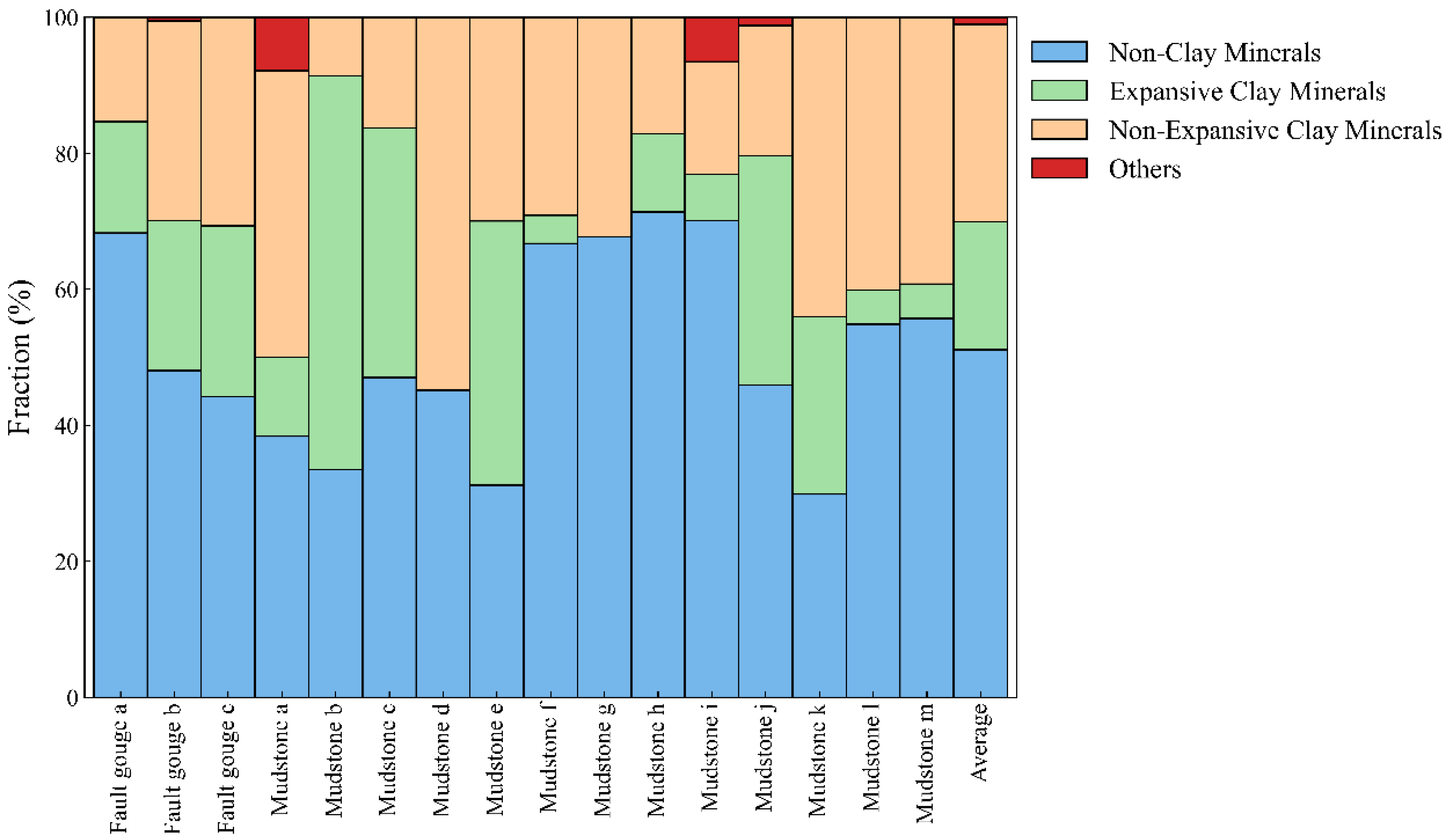
The XRD analysis results (Figure 2) indicate that the mineral composition of fault gouge is similar to that of adjacent mudstone. On average, non-clay minerals, primarily quartz, account for 51.86%; expansive clay minerals, mainly montmorillonite, for 18.11%; non-expansive clay minerals, predominantly kaolinite, for 28.91%; and other components for 1.11%. These results serve as the foundation for selecting and proportioning minerals in the laboratory preparation of remolded fault gouge samples. In addition to mineralogical composition, we refer to the classification framework of fault-related rocks proposed by Sibson [38]. He distinguished between cohesive fault rocks (e.g., cataclasites and mylonites) and incohesive fault materials such as clay-rich fault gouge. Based on field observations and sample texture, the collected fault gouge in this study shows weak cohesion and a very fine grain size, consistent with the characteristics of clay gouge, which typically forms in the shallow, brittle parts of fault zones. This supports the rationale for selecting clay minerals as the main constituents in our remolded experimental material.

2.2. Experimental Materials

Based on the analysis in Section 2.1, quartz, montmorillonite, and kaolinite are selected to prepare the simulated fault gouge for this study, with 425-grade Portland cement serving as the cementing material to simulate siliceous or calcareous cementation. The choice of Portland cement is supported by previous experimental studies, which have shown that its hydration products form interlocking crystalline structures resembling those in naturally cemented geomaterials. In particular, Portland cement has been widely used to simulate weak siliceous or calcareous bonding in soft rocks and soils, providing mechanical responses similar to natural fault gouge cementation [39]. Different degrees of cementation in the fault gouge are characterized by varying the cementing ratios. The cementing ratio is defined as the mass ratio of added cement to the mass of dried fault gouge, expressed as a percentage. Quartz particles represent the non-clay components, while montmorillonite and kaolinite represent expansive and non-expansive clays, respectively. To minimize the influence of particle size on the internal friction angle in the experimental results [40], quartz particles with sizes ranging from 250 and 380 μm are utilized. For montmorillonite and kaolinite, minerals with particle sizes of less than 45 μm are selected, ensuring their purity is above 90% to maintain the consistency and representativeness of the experimental materials. Although the grain size distribution of the natural fault gouge was not quantitatively measured, visual inspection during field sampling indicated a clay-rich matrix with dispersed silt-sized grains. The selected artificial materials and their particle sizes were chosen to approximate this observed texture as closely as possible under laboratory conditions.
Statistical analyses from previous studies indicate that the clay mineral content in natural fault gouge typically ranges from 20% to 80%, while the quartz content varies from approximately 10% to 70%. The contents of kaolinite and montmorillonite are generally within the range of 10% and 70%. These statistical ranges align well with the XRD analysis results of rock samples collected from the Liujiang Basin in North China.
By integrating the XRD data from field samples with existing literature, the mass proportions of the three minerals in the simulated fault gouge are determined to be 50% quartz, 20% montmorillonite, and 30% kaolinite. This proportion is comparable to that of the natural fault gouge or adjacent mudstone obtained from the studied profile located in Liujiang Basin, North China, as illustrated in Figure 2.

2.3. Experimental Design

To investigate the effects of water content and cementation degree on the shear characteristics of fault gouge, various parameter combinations are designed in the experiment. The water content is set at five levels: 10%, 15%, 20%, 25%, and 30%. Here, water content refers to the gravimetric water content, defined as the mass ratio of added water to the dry mineral mass. The cementation ratio, defined as the ratio of Portland cement mass to the total mineral mass, is established at 0%, 1%, and 3%. Normal pressures are applied at four levels: 100, 200, 300, and 400 kPa. Based on these parameters, a total of 60 fault gouge samples are prepared and subjected to direct shear tests. The experimental design is shown in Table 1. Additionally, to further understand the microstructural changes in fault gouge under varying conditions, scanning electron microscopy (SEM) analyses are performed on samples at different stages of the experiment to observe their microstructural characteristics under different water contents, cementation degrees, and normal pressures.

2.4. Experimental Procedure

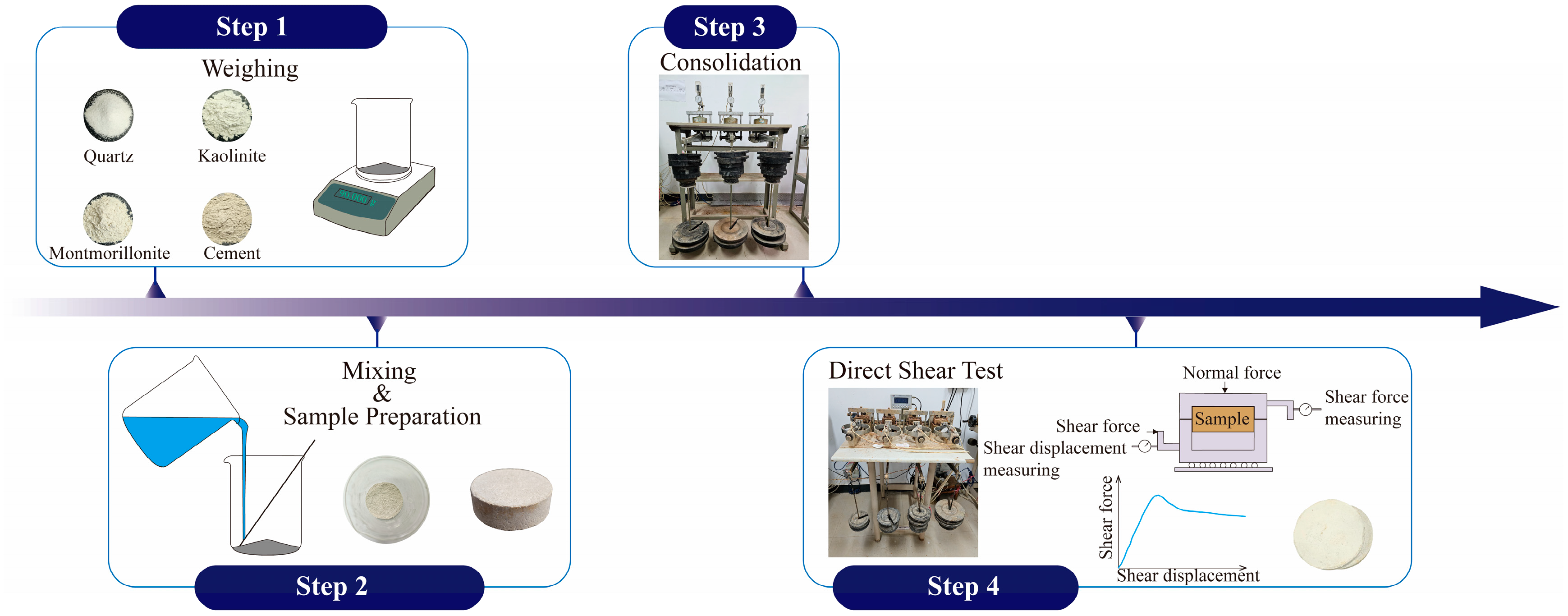
Figure 3 illustrates the shear testing procedure for the fault gouge samples. Prior to the experiments, all mineral samples used to prepare the fault gouge are placed in an oven at 70 °C and dried for 24 h to ensure complete dryness. After drying, the mineral samples are weighed together with Portland cement powder according to the predetermined mass ratios and degrees of cementation, followed by thorough mixing for at least 10 min to ensure uniform distribution of the dry components. The total mass of the dry components is calculated based on the fixed volume of the ring cutter mold (6.18 cm in diameter and 2 cm in height) to ensure a consistent dry density of 1.5 g/cm3 across all specimens.
Distilled water is then added to the mixture to achieve the specified water content levels, followed by further mixing using the same procedure to ensure consistent water distribution. The amount of added water is calculated so that the wet density matches the expected value based on the combined mass of solids and water. After uniform stirring, the mixture is molded into ring cutter samples. The total mass of each molded specimen is then measured to confirm that the actual wet density meets the target value.
The prepared ring cutter samples are placed in a consolidation apparatus and consolidated under a pressure of 400 kPa for 2 h to ensure the stability and consistency of the samples. Following consolidation, the samples undergo geotechnical direct shear tests using a ZJ-4 direct shear apparatus (Guodian Nanjing Automation Co., Ltd., Nanjing, China) under four normal pressures: 100, 200, 300, and 400 kPa. The horizontal shear displacement rate is set at 0.8 mm/min throughout the test. Each shear test is terminated once the horizontal displacement reaches 8 mm, which ensures full development of post-peak shear behavior.
Under these experimental conditions, shear stress–shear displacement curves are obtained for the fault gouge samples at each water content and degree of cementation. Shear strength parameters—cohesion (c) and internal friction angle (φ)—are determined based on the Mohr–Coulomb failure criterion. Specifically, the peak shear stress under each normal stress level (100, 200, 300, and 400 kPa) is plotted as the vertical axis against the corresponding normal stress as the horizontal axis. A linear regression is then performed on the peak points. The intercept of the best-fit line corresponds to the cohesion c, while the slope of the line determines the internal friction angle φ, calculated as φ = arctan (slope).
These experimental procedures are designed to systematically investigate the shear characteristics of fault gouge under varying physical conditions, providing experimental data and theoretical support for further exploration of the mechanical behavior and deformation mechanisms of fault gouge. The findings are expected to offer valuable insights for assessing fault stability, particularly in applications related to underground gas storage and geological sequestration.

3. Results

3.1. Shear Stress–Displacement Curves of Fault Gouge

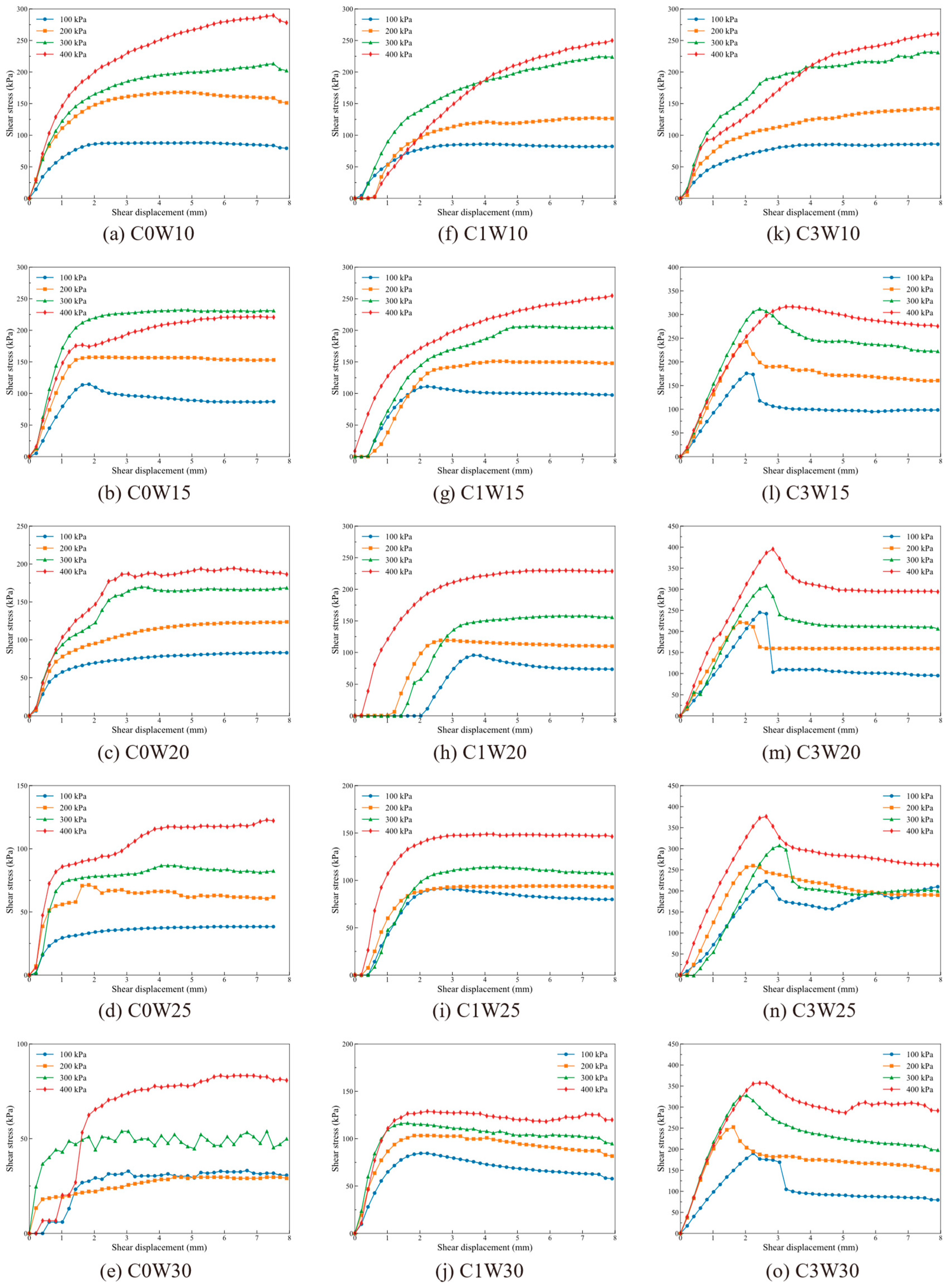
Figure 4 presents the shear stress–displacement curves of fault gouge under different degrees of cementation (C) and water content (W). Careful inspection shows two fundamental curve shapes. The first rises to a peak and then drops steeply—a “cliff-type” profile that occurs mainly in the highly-cemented C3 series, particularly at W20–W30, and signals a sudden loss of load-carrying capacity characteristic of brittle failure. The second shape, typical of the low- to moderate-cemented C0 and C1 series, slopes gently into a plateau or only mild softening after the peak, indicating ductile deformation governed by ongoing particle rearrangement.
The coexistence of these two curve families demonstrates that when cementation becomes sufficiently strong, the fault gouge as a whole evolves from a loose soil to a weakly cemented rock, and its failure mode shifts from ductile to brittle. This cementation-controlled ductile–brittle transition is consistent with the findings of Ismail et al. [39], who reported that increasing the amount of bonding in granular materials ultimately converts ductile yielding to brittle failure. Water content acts cooperatively: higher moisture lowers the effective normal stress along potential shear planes, so at the highest cementation level, the bonded skeleton collapses rapidly once peak strength is reached, producing the cliff-type drops seen in Figure 4m,n,o. In sum, abundant bonding together with pore water transforms fault gouge from a medium that can dissipate energy through plastic deformation into one that fractures abruptly upon reaching its peak strength.
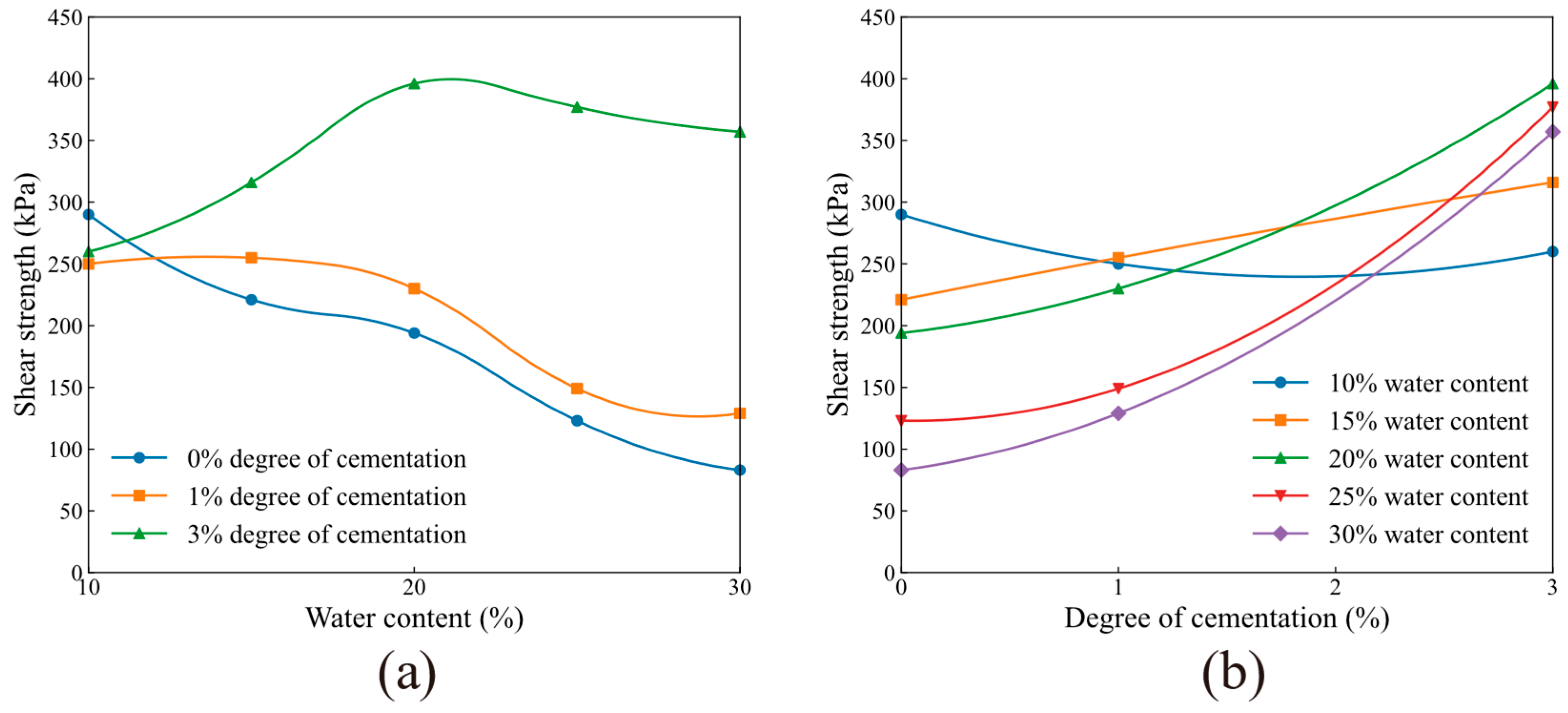
To facilitate a more intuitive analysis of the effects of water content and degree of cementation on the shear strength of fault gouge, the maximum shear stress under a normal pressure of 400 kPa is defined as the shear strength, and then the relationships between shear strength and water content as well as degree of cementation are plotted, as shown in Figure 5.
Figure 5a shows that the shear strength of fault gouge initially increases and then decreases with increasing water content. As the degree of cementation increases, the magnitude of the strength increase becomes larger, while the magnitude of the subsequent decrease becomes smaller. Specifically, at a cementation degree of 0%, there is no initial increase in shear strength (0% increase), but a significant decrease of 71% is observed at higher water contents. At 1% cementation, the strength increases by 2% before decreasing by 49%. At 3% cementation, the strength increases by 52% and then decreases by only 10%.
Figure 5b illustrates the variation in shear strength with the degree of cementation for fault gouge samples at different water contents. As the water content increases, the effect of increasing cementation degree on shear strength shifts from a decreasing to an increasing trend. The magnitude of the strength change progressively becomes larger with higher water content, showing percentage changes of −10%, +43%, +104%, +207%, and +330%, respectively.
These observations indicate that the two variables exert opposite first-order influences on shear strength: rising water content tends to weaken the gouge, whereas increasing cementation systematically strengthens it. The interplay of these opposing effects gives rise to the nonlinear dependence of shear strength on both water content and cementation degree. Mechanistically, initial pore water can enhance bond mobilization and promote slight dilative hardening in a well-cemented matrix, but once the voids become saturated, lubrication along nascent shear planes lowers effective normal stress and accelerates bond breakage, causing strength to decline. In essence, the balance between bond stiffening (from cement) and bond softening or slip facilitation (from water) controls the peak and post-peak strength response of the fault gouge [28].
In subsequent sections, an in-depth analysis of these influencing mechanisms will be conducted by considering factors such as cohesion, internal friction angle, and microstructure.

3.2. Cohesion

3.2.1. Relationship Between Cohesion and Water Content

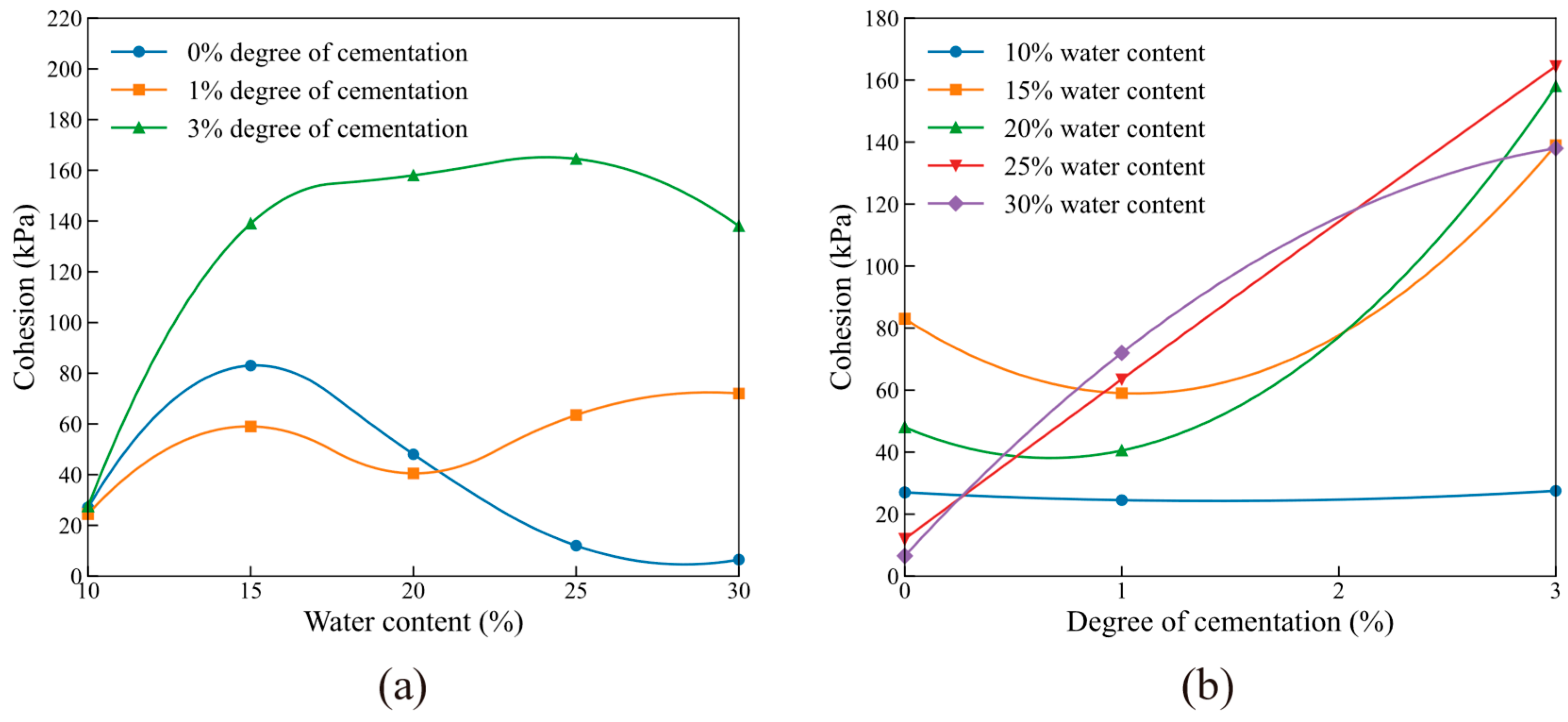
Figure 6a illustrates the relationship curves between the cohesion (c) of fault gouge and water content under different degrees of cementation. The experimental results indicate that, with increasing water content, the cohesion of fault gouge exhibits a “first increase, then decrease” trend at cementation degrees of 0% and 3%. Specifically, at a cementation degree of 0%, the cohesion increases from 27 kPa at 10% water content to 83 kPa at 15% water content but then sharply decreases to 6.5 kPa at 30% water content. For a cementation degree of 3%, the cohesion increases from 27.5 kPa at 10% water content to 164.5 kPa at 25% water content, before slightly decreasing to 138 kPa at 30% water content. The reason for this phenomenon is that with a moderate increase in water content, the adsorption of water enhances the bonding forces between particles, leading to an increase in cohesion. However, as water content continues to increase, excessive water fills the pores between particles. Additionally, the thickness of the adsorbed water layers on the surfaces of clay mineral particles and cementing substances in the fault gouge increases [41]. This weakens the connections between particles as well as between particles and cementing materials, resulting in a decrease in cohesion [42].
In contrast, the samples with a cementation degree of 1% exhibit a different trend in cohesion with increasing water content. As the water content increases, the cohesion increases from 24.5 kPa to an initial peak of 59 kPa. Instead of decreasing directly, it fluctuates within the range of 40–80 kPa. During this stage, the water, cementing materials, and clay particles within the sample appear to reach an equilibrium, maintaining the overall cohesion at a relatively stable level.

3.2.2. Relationship Between Cohesion and Degree of Cementation

Figure 6b illustrates the relationship between the cohesion (c) of fault gouge and the degree of cementation under varying water content conditions. Overall, as the degree of cementation increases, the cohesion of the fault gouge exhibits an increasing trend across different water contents. However, for samples with water contents of 10%, 15%, and 20%, the cohesion exhibits a slight decrease when the degree of cementation increases from 0% to 1%, decreasing by 9.3%, 28.9%, and 15.6%, respectively. It then begins to increase with further increases in cementation degree. This occurs because at a cementation degree of 1%, the amount of cementing material within the samples is relatively low. Additionally, at lower water contents, the cementing materials are not fully wetted, and their cementing effect is not fully developed. The presence of unwetted cementing materials may even increase the overall rigidity of the samples, thereby reducing the cohesion [28].
As the degree of cementation and water content continue to increase, the amount of cementing materials within the samples rises. The enhanced bonding effect of the cementing materials leads to an increase in cohesion. When the water content reaches 25% or 30%, the cohesion consistently increases with the degree of cementation, which indicates that the role of cementing materials becomes more significant under high-water-content conditions.

3.3. Internal Friction Angle

3.3.1. Relationship Between Internal Friction Angle and Water Content

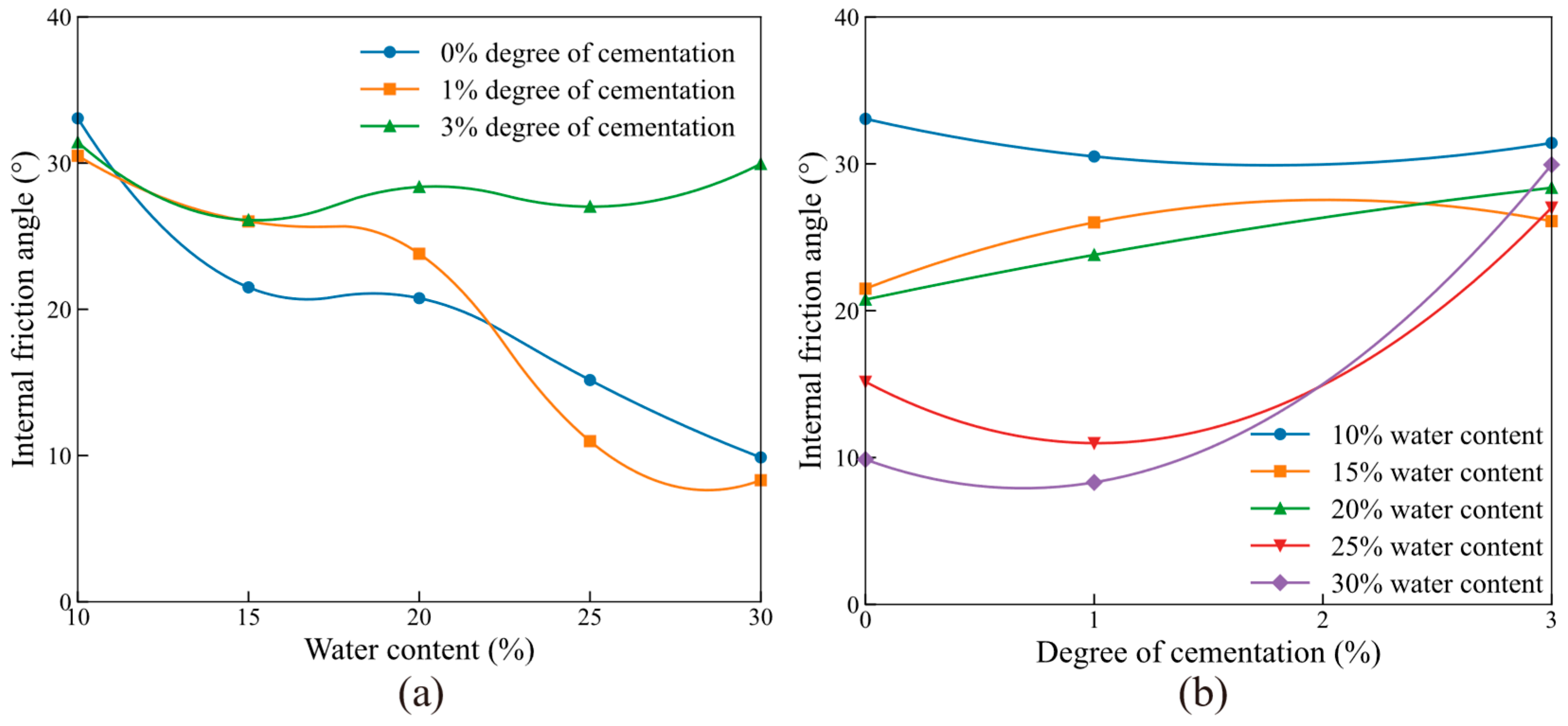
Figure 7a illustrates the variation in the internal friction angle of fault gouge with water content under varying degrees of cementation. The overall trend indicates that with increasing water content, the internal friction angle exhibits a significant decrease, demonstrating a negative correlation between water content and internal friction angle [31]. This suggests that the addition of water forms a thin film between the particles, leading to a reduction in the internal friction angle. This effect is particularly significant for fault gouge samples with low degrees of cementation [41].
In the case of a cementation degree of 0%, when the water content increases from 10% to 30%, the internal friction angle of the fault gouge significantly decreases from 33.06° to 9.87°, a reduction of up to 70.1%. This result indicates that under conditions without cementing materials, the increase in water greatly reduces the friction between particles.
For samples with a cementation degree of 3%, as the water content increases from 10% to 30%, the internal friction angle decreases from 31.42° to 29.94°, a reduction of only 4.7%. This shows that the increase in cementing materials offsets the lubrication effect brought about by the additional water to some extent, allowing the internal friction angle to remain at a relatively high level.

3.3.2. Relationship Between Internal Friction Angle and Degree of Cementation

Figure 7b illustrates the relationship between the internal friction angle of fault gouge and the degree of cementation under varying water content conditions. As the degree of cementation increases, the internal friction angle of the fault gouge gradually tends to converge. This indicates that the degree of cementation plays a dominant role in controlling the variation in the internal friction angle. For samples with a cementation degree of 0%, the internal friction angle exhibits a wide range of variation, distributed between 9.87° and 33.06°. However, with the increase in the degree of cementation—particularly when it reaches 3%—the variation range of the internal friction angle significantly narrows, concentrating between 28.37° and 31.42°.
This phenomenon occurs because the increase in the degree of cementation leads to a greater amount of cementing material within the fault gouge samples. The voids between particles are filled, interparticle contacts increase, and the cementation strength is enhanced. As a result, the negative impact of increased water content on the internal friction angle is mitigated [28].

4. Discussion

4.1. Microstructure Variation in Different Types of Remolded Fault Gouge

To further investigate the mechanisms underlying the differences in shear performance of fault gouge under varying water contents and degrees of cementation, scanning electron microscopy (SEM) analyses were performed on fault gouge samples subjected to a normal pressure of 200 kPa.
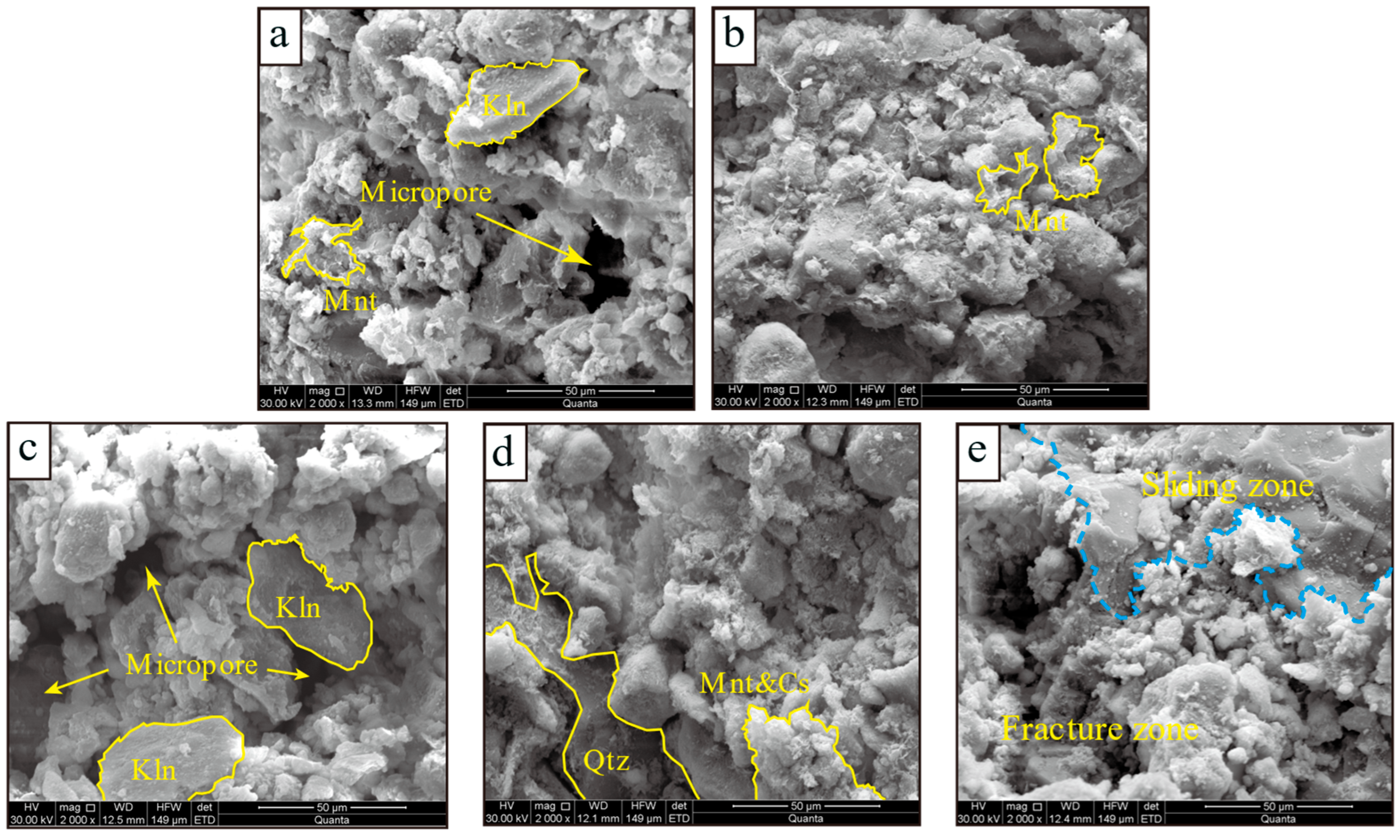
Figure 8a,b,d present scanning electron microscopy (SEM) images of fault gouge with 20% water content under three types of cementation degrees (0, 1%, 3%). At a cementation degree of 0%, large voids between particles were observed, indicating a loose structure with insufficient cementing material. This condition resulted in weak interparticle interactions and low shear strength. As the cementation degree increased from 0% to 3%, the amount of cementing substances formed by Portland cement gradually increased. These substances, together with montmorillonite, coated the surfaces of quartz and kaolinite particles, filling the interparticle voids and enhancing the bonding strength among them [43]. This change significantly improved the integrity of the fault gouge, reduced microcracking, and led to tighter interparticle connections. Macroscopically, both shear strength and cohesion increased with the cementation degree, as illustrated in Figure 5b and Figure 6b. This indicates that the presence of cementing substances not only markedly enhanced the shear resistance of the fault gouge but also altered its failure mode from particle sliding to the fracturing of the cementing material.
Figure 8c–e show SEM images of fault gouge with a cementation degree of 3% at varying water contents. At a low water content (10%), obvious microcracks were observed in the samples, attributed to the low plasticity and high rigidity resulting from insufficient water in kaolinite and montmorillonite. This further contributed to increased brittleness and reduced shear strength of the fault gouge (as shown in Figure 4 and Figure 5). With increasing water content, more network-like cementing substances formed due to the swelling of montmorillonite particles as they absorbed water [44]. Consequently, microcracks decreased, the pore structure became denser, and the overall integrity of the samples was enhanced, leading to higher shear strength values at this stage [45]. However, when the water content continued to increase to 30%, a significant sliding zone was observed on the shear surface of the fault gouge sample [46]. This indicates that excessive water filled the voids between particles and cementing substances, weakening the cementing effect of the cementing materials, reducing the friction between particles, and changing the failure mode of the fault gouge from fracturing of the cementing material to wet sliding between particles. This led to a significant decrease in shear strength. This phenomenon correlates with the trend observed in Figure 7a and Figure 8a, indicating that high water content diminishes the strength of the fault gouge to some extent.

4.2. Influence of Clay Content, Water Content, and Cementation on Shear Strength Parameters

While previous sections mentioned above focused on how variations in water content and cementation degree influence the shear strength parameters of fault gouge, it is equally important to consider the role of mineralogical composition—particularly clay content—in controlling these relationships. Clay minerals, due to their strong water absorption and plasticity, can significantly affect how fault gouge responds to changes in water content and cementation. Therefore, this section incorporates clay content as an additional variable and investigates its coupled influence with water content and cementation degree on cohesion and internal friction angle, based on a synthesis of previous studies [28,31,41] and this study’s results.

4.2.1. Cohesion with Variable Clay Content

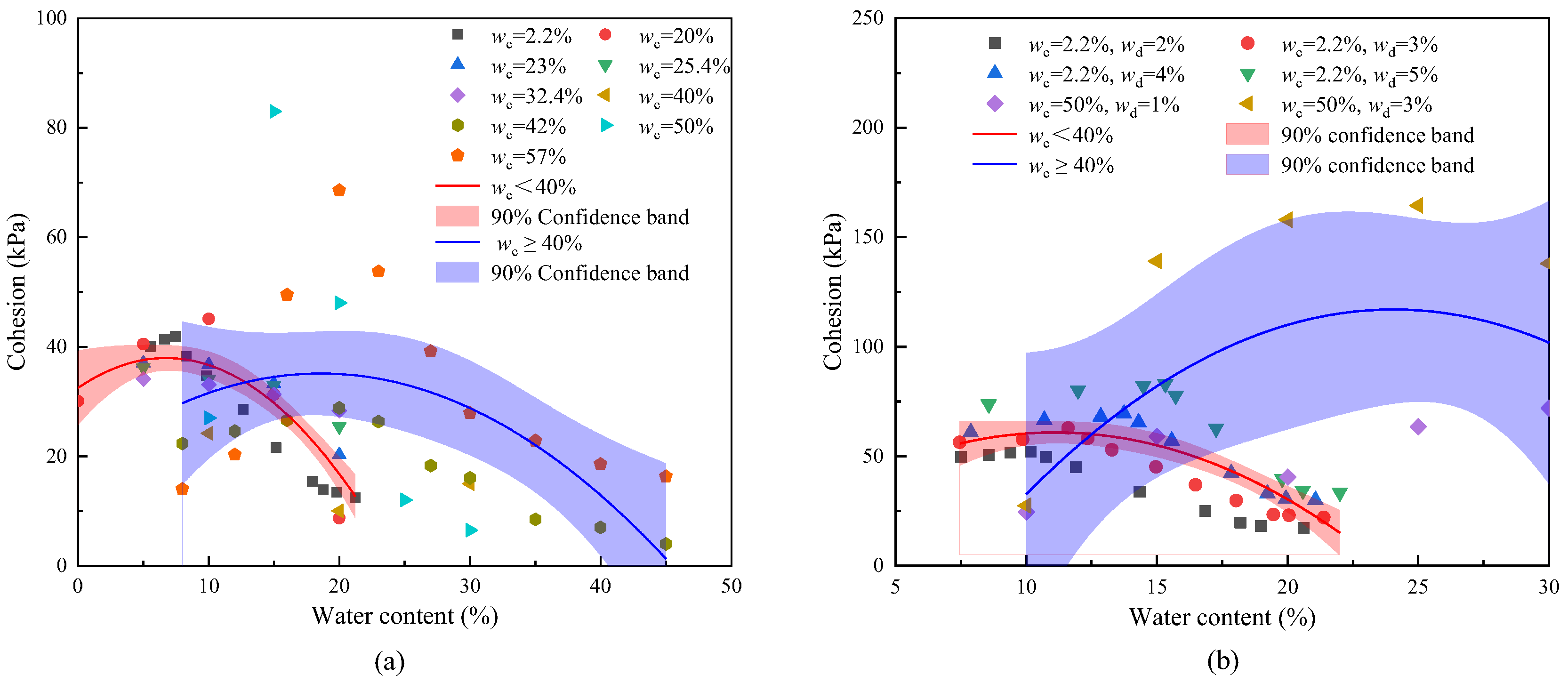
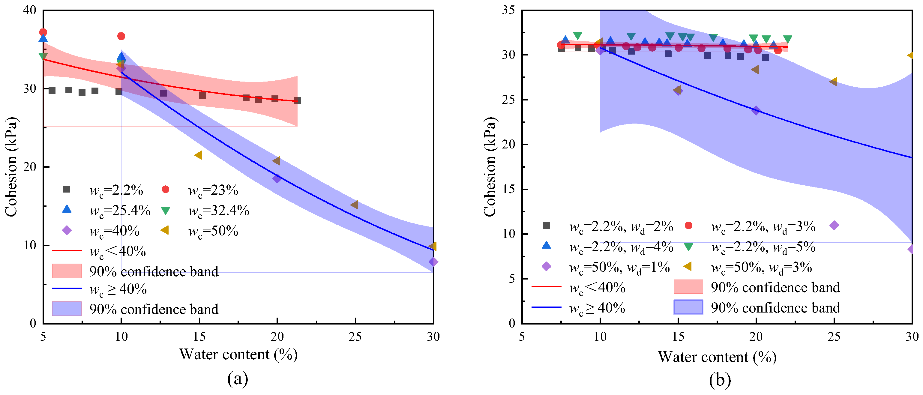
Figure 9 presents the relationship between water content and cohesion under different clay contents and cementation degrees. Both uncemented and cemented fault gouge samples show a similar trend: cohesion increases with water content initially, reaches a peak, and then declines as water content continues to rise. This pattern is consistent with the experimental results in Figure 6a.
The water content at which peak cohesion occurs is affected by clay content. As shown in Figure 9a, for samples with clay content below 40%, the cohesion peaks at a water content of approximately 6–8%. In contrast, for samples with higher clay content (>40%), the peak occurs at around 20–25%. Figure 9b indicates that this trend also holds true for samples with different cementation degrees, regardless of clay content. While increasing the cementation degree enhances the overall cohesion, it does not change the trend of cohesion with water content, nor the inflection point’s dependence on clay content.
This behavior is attributed to the effect of clay content on the liquid and plastic limits of the fault gouge [47]. Higher clay content corresponds to a higher capacity for water retention before reaching saturation. For low-clay-content samples, the liquid limit is relatively low, and the cohesion begins to decrease once particle surfaces become saturated and water starts acting as a lubricant [48,49]. For high-clay-content samples, the higher liquid limit allows for greater water absorption before cohesion begins to decline. Therefore, the peak cohesion point reflects the critical water content at which the material behavior transitions from brittle to plastic.

4.2.2. Internal Friction Angle with Variable Clay Content

Figure 10 shows the relationship between water content and internal friction angle under both uncemented and cemented conditions. Overall, the internal friction angle decreases with increasing water content. However, the rate of decrease varies with clay content. Samples with high clay content exhibit a more pronounced reduction in internal friction angle compared to low-clay-content samples [50].
For example, in Figure 10a, the internal friction angle of a sample with 2.2% clay content decreases only slightly—from 29.72° to 28.5°—as water content increases from 5% to 22%, a reduction of just 4.1%. In contrast, a sample with 50% clay content shows a dramatic decrease—from 33.06° to 9.87°—as water content rises from 10% to 30%, corresponding to a 70.1% reduction. This pattern is also evident in Figure 10b under cemented conditions. Similar to cohesion, increasing the degree of cementation raises the absolute value of the internal friction angle but does not alter its trend with respect to water content or its sensitivity to clay content.
This phenomenon can be explained by the fact that fine clay minerals, in contrast to coarse particles like quartz, absorb water more readily and become enveloped in water films. This reduces interparticle bonding and friction, especially under high-water-content conditions. Therefore, fault gouge with a higher clay content is more sensitive to increases in water content in terms of shear resistance reduction.

4.3. Shear Strength Model for High-Clay-Content Fault Gouge

The Mohr–Coulomb criterion is a widely accepted theoretical model for evaluating the shear strength of geomaterials, expressing shear strength τ as a function of cohesion c, internal friction angle φ, and normal stress σ, in the following form:
τ = c + σ tan φ
However, the classical Mohr–Coulomb model cannot be directly applied to fault gouge with variable water contents and cementation degrees because its parameters do not explicitly reflect the influence of these evolving hydro-mechanical conditions.
In recent years, several studies have attempted to incorporate such factors—particularly water content, suction, and stress—into empirical or extended formulations of the Mohr–Coulomb model, improving its applicability to unsaturated soils and soft rock materials [51,52,53,54,55]. Inspired by these developments, we introduce the effects of water content and cementation degree into the strength model for fault gouge, and the criterion is rewritten as
τ ( W , D ) = c ( W , D ) + σ tan [ φ ( W , D ) ]
where W (%) is water content and D (%) is degree of cementation. The experimental results presented in Section 3 and Section 4.2 demonstrate that cohesion exhibits a nonlinear response to water content, increasing initially and then decreasing, while increasing cementation degree leads to a monotonic enhancement of cohesion. In contrast, the internal friction angle tends to decrease as water content rises, but this softening effect becomes less pronounced under higher cementation conditions. These tendencies are captured by
c ( W , D ) = A W k 1 e λ 1 W + α D m  
φ ( W , D ) = C e k 2 W e λ 2 D tan [ φ ( W , D ) ]
where A, α, C, k1, λ1, m, k2, and λ2 are empirical constants. Because all measured friction angles lie between 10° and 40°, tan φ differs from φ (in radians) by <7%; the single function φ(W, D) therefore replaces tan φ(W, D) in Equation (2) without an appreciable loss of accuracy and keeps the parameter set compact. Substituting Equations (3) and (4) into Equation (2) gives the semi-empirical shear strength model
τ = A W k 1 e λ 1 W + α D m + σ C e k 2 W e λ 2 D
where τ (kPa) is the shear strength, and σ (kPa) is the applied normal stress. This model maintains the fundamental structure of the Mohr–Coulomb criterion while effectively capturing the nonlinear and coupled effects of water and cementation on shear strength.
To calibrate and verify the model, a total of 60 fault gouge samples obtained from the experiments described in Section 2 and Section 3 are used. The dataset is divided using a random seed in Python 3.11.7, with 40 samples used for training and parameter fitting, and the remaining 20 samples used for model testing. The empirical parameters in the model were obtained by nonlinear least-squares fitting using the curve_fit function in Python (SciPy library). The fitting process was conducted by minimizing the squared difference between the predicted and measured shear strength on the training set. Based on the training data, the fitted shear strength prediction model is expressed as follows:
τ = 10 6 W 9.496 e 0.524 W + 0.00540 D 8.840 + σ 0.603 e 0.0319 W e 0.740 D
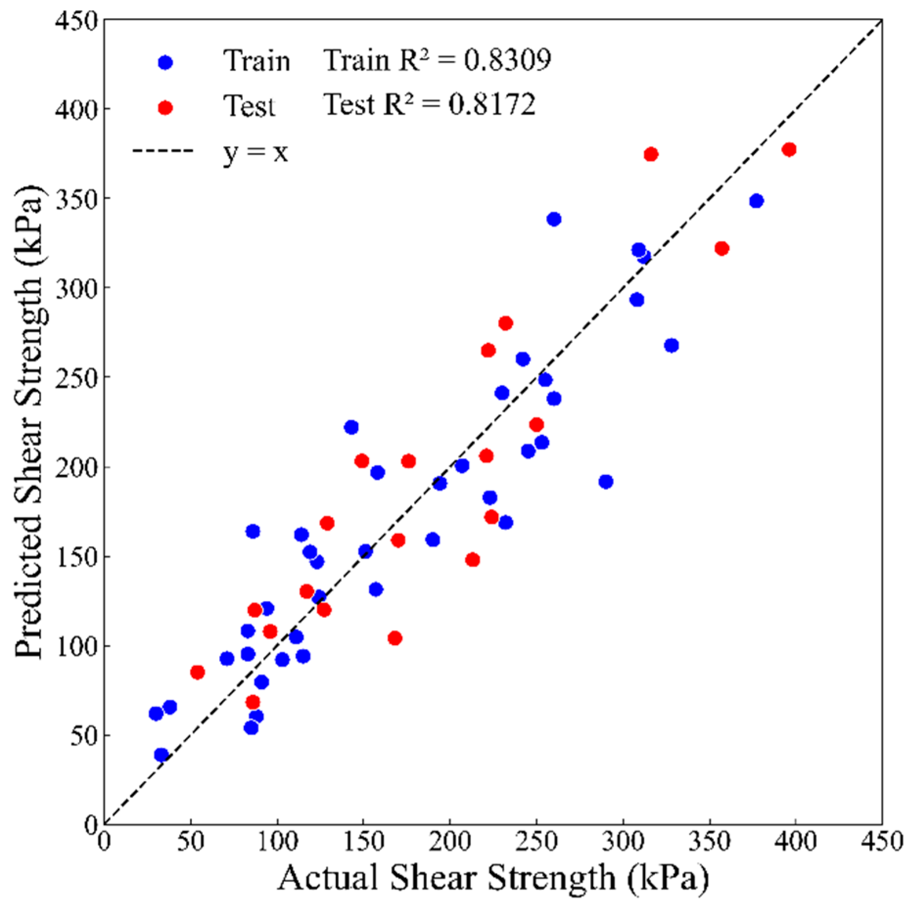
The comparison between predicted and measured shear strength is shown in Figure 11.
As illustrated in the figure, there is a strong correlation between predicted and actual values. It is generally accepted that a coefficient of determination R2 > 0.8 indicates good predictive reliability [56]. In this study, the model achieved R2 = 0.8309 on the training set and R2 = 0.8172 on the test set, demonstrating both strong fitting performance and generalization capability. Most data points lie near the y = x line, further confirming the model’s ability to accurately predict shear strength under diverse conditions. These results validate the applicability and robustness of the proposed model and provide a solid foundation for fast shear strength prediction under complex hydro-mechanical–cementation conditions, supporting future engineering applications and numerical simulation studies. It should be noted that this model is developed based on experimental results and supported by literature data (as show in Figure 9 and Figure 10). It is applicable to fault gouge with high clay content (typically >30%) under unsaturated conditions and with silicate-based cementation. While it extends the Mohr–Coulomb criterion, the model also incorporates the effect of weak cementation through the evolution of cohesion. Its applicability may be limited for materials with highly localized structural failure or complex degradation mechanisms beyond the scope of cohesion–friction description.

5. Conclusions

Through direct shear tests conducted on remolded fault gouge samples with varying water contents (10–30%) and cementation degrees (0%, 1%, 3%), key shear strength parameters—including shear strength, cohesion, and internal friction angle—are systematically analyzed. Coupled with correlation analysis and model development, the following conclusions are drawn:
(1) Shear Strength:
Higher water content reduces the shear strength of fault gouge, whereas a greater degree of cementation enhances it. When cementation becomes strong, the material’s failure mode shifts from ductile sliding to brittle, cliff-type rupture. Because these two factors act in opposition, their coupling produces a nonlinear response: at low cementation, water simply weakens the gouge, but at high cementation, a small amount of moisture can first mobilize additional bonding and raise the peak strength before further wetting lubricates the shear plane and triggering a sharp strength drop. Thus, cementation not only counteracts the softening imposed by water but also governs whether the gouge behaves like a ductile soil or a brittle, weakly cemented rock.
(2) Cohesion:
Cohesion exhibits a peak at intermediate water contents. As cementation degree increases, cohesion consistently rises, regardless of water content. The presence of cementing agents strengthens the bonding between particles, enhancing the material’s overall resistance to shear.
(3) Internal Friction Angle:
A clear inverse relationship exists between internal friction angle and water content. This decline is more significant in samples with low cementation. Under high cementation conditions, the internal friction angle shows minimal variation across different water contents, indicating that the added cementing materials stabilize the grain structure and reduce the water sensitivity of interparticle friction.
(4) Regulatory Role of Clay Content:
Clay content does not alter the overall trend of how shear strength parameters respond to changes in water content and cementation degree, but it significantly influences the magnitude of these responses. As clay content increases, the water content corresponding to peak cohesion and shear strength shifts to higher values, and the internal friction angle becomes more sensitive to moisture, showing a steeper decline. This indicates that fault gouge with a higher clay content tends to have higher plastic limits and exhibits stronger hydro-mechanical sensitivity.
(5) Development and Validation of Predictive Models:
A semi-empirical model is developed to quantify the shear strength of fault gouge as a function of water content and cementation degree by incorporating experimentally observed nonlinear and coupled effects into an extended Mohr–Coulomb framework. The proposed model accurately predicts both cohesion and internal friction angle and demonstrates strong agreement with experimental results (with R2 = 0.8309 for training and R2 = 0.8172 for testing). The model provides a practical and physically meaningful tool for estimating the shear strength behavior of fault gouge under variable hydro-mechanical conditions, offering valuable insights for fault stability assessment in geotechnical and geological engineering.

Author Contributions

Conceptualization, W.W., H.L., H.P. and S.B.; Methodology, W.W.; Validation, H.L.; Formal analysis, W.W.; Investigation, W.W. and S.B.; Resources, H.L.; Data curation, W.W.; Writing—original draft, W.W.; Writing—review & editing, W.W. and H.L.; Supervision, H.L.; Project administration, H.L.; Funding acquisition, H.L. All authors have read and agreed to the published version of the manuscript.

Funding

This research was funded by the National Natural Science Foundation (U22A20166), Excellent Young Scientists Fund Program of National Natural Science Foundation of China (No. 52122403), and Natural Science Foundation of Wuhan (No. 2024040701010062).

Institutional Review Board Statement

Not applicable.

Informed Consent Statement

Not applicable.

Data Availability Statement

The original contributions presented in this study are included in the article. Further inquiries can be directed to the corresponding author.

Conflicts of Interest

The authors declare no conflict of interest.

References

  1. Yang, S.; Hu, S.; Qi, Z.; Li, J.; Yan, W.; Huang, X.; Ao, X.; Yuan, Y. Stability evaluation of fault in hydrocarbon reservoir-based underground gas storage: A case study of W gas storage. Fuel 2024, 357, 129657. [Google Scholar] [CrossRef]
  2. Jing, J.; Yang, Y.; Tang, Z. Assessing the influence of injection temperature on CO2 storage efficiency and capacity in the sloping formation with fault. Energy 2021, 215, 119097. [Google Scholar] [CrossRef]
  3. Dong, D.-W.; Li, J.-Y.; Yang, Y.-H.; Wang, X.-L.; Liu, J. Improvements to the fuzzy mathematics comprehensive quantitative method for evaluating fault sealing. Pet. Sci. 2017, 14, 276–285. [Google Scholar] [CrossRef]
  4. Zhou, X.; Wang, D.; Yu, H.; Yang, H.; Li, L. Major controlling factors and hydrocarbon accumulation models of large-scale lithologic reservoirs in shallow strata around the Bozhong sag, Bohai Bay Basin, China. Pet. Explor. Dev. 2022, 49, 758–769. [Google Scholar] [CrossRef]
  5. Zhong, Z.; Xu, C.; Hu, Y.; Zhang, F.; Wu, F.; Li, B. Frictional strength and sliding behaviors of an analogue rock-fault structure: A laboratory study. Int. J. Rock Mech. Min. Sci. 2024, 174, 105665. [Google Scholar] [CrossRef]
  6. Bense, V.F.; Gleeson, T.; Loveless, S.E.; Bour, O.; Scibek, J. Fault zone hydrogeology. Earth-Sci. Rev. 2013, 127, 171–192. [Google Scholar] [CrossRef]
  7. Fletcher, J.M.; Teran, O.J.; Rockwell, T.K.; Oskin, M.E.; Hudnut, K.W.; Spelz, R.M.; Lacan, P.; Dorsey, M.T.; Ostermeijer, G.; Mitchell, T.M.; et al. An analysis of the factors that control fault zone architecture and the importance of fault orientation relative to regional stress. GSA Bull. 2020, 132, 2084–2104. [Google Scholar] [CrossRef]
  8. Hattori, I.; Yamamoto, H. Rock Fragmentation and Particle Size in Crushed Zones by Faulting. J. Geol. 1999, 107, 209–222. [Google Scholar] [CrossRef]
  9. Faulkner, D.R.; Mitchell, T.M.; Healy, D.; Heap, M.J. Slip on “weak” faults by the rotation of regional stress in the fracture damage zone. Nature 2006, 444, 922–925. [Google Scholar] [CrossRef]
  10. Williams, R.T.; Mozley, P.S.; Sharp, W.D.; Goodwin, L.B. U-Th Dating of Syntectonic Calcite Veins Reveals the Dynamic Nature of Fracture Cementation and Healing in Faults. Geophys. Res. Lett. 2019, 46, 12900–12908. [Google Scholar] [CrossRef]
  11. Choi, J.-H.; Edwards, P.; Ko, K.; Kim, Y.-S. Definition and classification of fault damage zones: A review and a new methodological approach. Earth-Sci. Rev. 2016, 152, 70–87. [Google Scholar] [CrossRef]
  12. Viola, G.; Scheiber, T.; Fredin, O.; Zwingmann, H.; Margreth, A.; Knies, J. Deconvoluting complex structural histories archived in brittle fault zones. Nat. Commun. 2016, 7, 13448. [Google Scholar] [CrossRef]
  13. Hassanbeigi, E.; Solgi, A.; Arian, M.; Uromeihy, A. Impact of Brittle Faults with Varying Geometrical Structures on Rock Mass Engineering Properties in the North Tehran and Pourkan Verdij Fault Zones, Iran. Geotech. Geol. Eng. 2024, 42, 3063–3082. [Google Scholar] [CrossRef]
  14. Rutter, E.H.; Faulkner, D.R.; Brodie, K.H.; Phillips, R.J.; Searle, M.P. Rock deformation processes in the Karakoram fault zone, Eastern Karakoram, Ladakh, NW India. J. Struct. Geol. 2007, 29, 1315–1326. [Google Scholar] [CrossRef]
  15. Verberne, B.A.; Chen, J.; Niemeijer, A.R.; De Bresser, J.H.P.; Pennock, G.M.; Drury, M.R.; Spiers, C.J. Microscale cavitation as a mechanism for nucleating earthquakes at the base of the seismogenic zone. Nat. Commun. 2017, 8, 1645. [Google Scholar] [CrossRef] [PubMed]
  16. Salomon, E.; Rotevatn, A.; Kristensen, T.B.; Grundvåg, S.-A.; Henstra, G.A. Microstructure and fluid flow in the vicinity of basin bounding faults in rifts—The Dombjerg Fault, NE Greenland rift system. J. Struct. Geol. 2021, 153, 104463. [Google Scholar] [CrossRef]
  17. Williams, R.T.; Fagereng, Å. The Role of Quartz Cementation in the Seismic Cycle: A Critical Review. Rev. Geophys. 2022, 60, e2021RG000768. [Google Scholar] [CrossRef]
  18. Doglioni, C.; Barba, S.; Carminati, E.; Riguzzi, F. Fault on–off versus coseismic fluids reaction. Geosci. Front. 2014, 5, 767–780. [Google Scholar] [CrossRef]
  19. Rathnaweera, T.D.; Wu, W.; Ji, Y.; Gamage, R.P. Understanding injection-induced seismicity in enhanced geothermal systems: From the coupled thermo-hydro-mechanical-chemical process to anthropogenic earthquake prediction. Earth-Sci. Rev. 2020, 205, 103182. [Google Scholar] [CrossRef]
  20. Ban, S.; Liu, H.; Mao, H.; Shi, X.; Qiu, X.; Liu, M.; Min, Z.; Song, Y.; Wei, X. Numerical Tracking of Natural Gas Migration in Underground Gas Storage with Multilayered Sandstone and Fault-Bearing Caprocks. Energies 2023, 16, 4936. [Google Scholar] [CrossRef]
  21. Ikari, M.J.; Marone, C.; Saffer, D.M. On the relation between fault strength and frictional stability. Geology 2011, 39, 83–86. [Google Scholar] [CrossRef]
  22. Scuderi, M.M.; Collettini, C.; Marone, C. Frictional stability and earthquake triggering during fluid pressure stimulation of an experimental fault. Earth Planet. Sci. Lett. 2017, 477, 84–96. [Google Scholar] [CrossRef]
  23. An, M.; Zhang, F.; Min, K.; Elsworth, D.; Marone, C.; He, C. The Potential for Low-Grade Metamorphism to Facilitate Fault Instability in a Geothermal Reservoir. Geophys. Res. Lett. 2021, 48, e2021GL093552. [Google Scholar] [CrossRef]
  24. Geng, N.; Yao, X.; Chen, Y. Primary study on mechanical properties of the gouge for five large faults in China. Earthq. Res. China 1985, 4, 62–67. Available online: https://www.istis.sh.cn/metadata/resource/did:8f296240adff66c9c21e0f64420e0d85 (accessed on 10 July 2025). (In Chinese).
  25. Kenigsberg, A.R.; Rivière, J.; Marone, C.; Saffer, D.M. The Effects of Shear Strain, Fabric, and Porosity Evolution on Elastic and Mechanical Properties of Clay-Rich Fault Gouge. J. Geophys. Res. Solid Earth 2019, 124, 10968–10982. [Google Scholar] [CrossRef]
  26. Numelin, T.; Marone, C.; Kirby, E. Frictional properties of natural fault gouge from a low-angle normal fault, Panamint Valley, California. Tectonics 2007, 26, TC2004. [Google Scholar] [CrossRef]
  27. Ashman, I.R.; Faulkner, D.R. The Effect of Clay Content on the Dilatancy and Frictional Properties of Fault Gouge. J. Geophys. Res. Solid Earth 2023, 128, e2022JB025878. [Google Scholar] [CrossRef]
  28. Wang, P.; Tan, W.; Ma, X.; Li, Z.; Liu, J.; Wu, Y. Relationship between strength parameter and water content of fault gouge with different degrees of consolidation. Rock Soil Mech. 2019, 40, 1657–1662. (In Chinese) [Google Scholar] [CrossRef]
  29. Bao, H.; Qi, Q.; Lan, H.; Yan, C.; Xu, W.; Liu, X.; Li, L. Shear Mechanical Behaviours and Multistrength Parameter Characteristics of Fault Gouge. Adv. Civ. Eng. 2019, 2019, 4208032. [Google Scholar] [CrossRef]
  30. Morrow, C.A.; Moore, D.E.; Lockner, D.A. The effect of mineral bond strength and adsorbed water on fault gouge frictional strength. Geophys. Res. Lett. 2000, 27, 815–818. [Google Scholar] [CrossRef]
  31. Qi, Q.; Bao, H.; Lan, H.; Yan, C.; Zhang, K. Behavior of shearing mechanics and characteristics of strain softening of fault gouge. J. Eng. Geol. 2019, 27, 1101–1109. (In Chinese) [Google Scholar] [CrossRef]
  32. Saffer, D.M.; Marone, C. Comparison of smectite- and illite-rich gouge frictional properties: Application to the updip limit of the seismogenic zone along subduction megathrusts. Earth Planet. Sci. Lett. 2003, 215, 219–235. [Google Scholar] [CrossRef]
  33. Billi, A.; Smeraglia, L.; Aldega, L.; Balsamo, F.; Barberio, M.D.; Boschi, C.; Caracausi, A.; Carminati, E.; Iannace, A.; Mercuri, M.; et al. Dolostone pulverization induced by coseismic rapid decompression of CO2-rich gas in nature (Matese, Apennines, Italy). Earth Planet. Sci. Lett. 2023, 604, 117996. [Google Scholar] [CrossRef]
  34. Gbaguidi, S.V.; Odunlami, N.E.G.; Zevounou, C.; Agbodjan, C.P. Variability of cohesion and angle of friction as a function of water content in fine soils in the municipality of Lalo (Benin). World J. Adv. Res. Rev. 2023, 20, 142–152. [Google Scholar] [CrossRef]
  35. Fisher, Q.J.; Knipe, R.J. Fault sealing processes in siliciclastic sediments. Geol. Soc. Lond. Spec. Publ. 1998, 147, 117–134. [Google Scholar] [CrossRef]
  36. Pei, Y.; Paton, D.A.; Knipe, R.J.; Wu, K. A review of fault sealing behaviour and its evaluation in siliciclastic rocks. Earth-Sci. Rev. 2015, 150, 121–138. [Google Scholar] [CrossRef]
  37. Ottesen Ellevset, S.; Knipe, R.J.; Svava Olsen, T.; Fisher, Q.J.; Jones, G. Fault controlled communication in the Sleipner Vest Field, Norwegian Continental Shelf; detailed, quantitative input for reservoir simulation and well planning. Geol. Soc. Lond. Spec. Publ. 1998, 147, 283–297. [Google Scholar] [CrossRef]
  38. Sibson, R.H. Fault rocks and fault mechanisms. J. Geol. Soc. Lond. 1977, 133, 191–213. [Google Scholar] [CrossRef]
  39. Ismail, M.A.; Joer, H.A.; Sim, W.H.; Randolph, M.F. Effect of Cement Type on Shear Behavior of Cemented Calcareous Soil. J. Geotech. Geoenviron. Eng. 2002, 128, 520–529. [Google Scholar] [CrossRef]
  40. Kim, K.Y.; Suh, H.S.; Yun, T.S.; Moon, S.-W.; Seo, Y.-S. Effect of particle shape on the shear strength of fault gouge. Geosci. J. 2016, 20, 351–359. [Google Scholar] [CrossRef]
  41. Kong, D.; Wan, R.; Zhao, C.; Dai, J.; Dong, T.; Ni, W.; Gao, J.; Wang, T. Effect of conglomeration gradation on loess shear strength with different water content. Sci. Prog. 2021, 104, 368504211010581. [Google Scholar] [CrossRef]
  42. Kang, Y.; Hou, C.; Liu, B.; Bai, W. Influence of Water Content on the Shear Strength of Rock Joints with Clay-Rich Fillings. Rock Mech. Rock Eng. 2023, 56, 1437–1449. [Google Scholar] [CrossRef]
  43. Hattab, M.; Hammad, T.; Fleureau, J.-M. Internal friction angle variation in a kaolin/montmorillonite clay mix and microstructural identification. Géotechnique 2015, 65, 1–11. [Google Scholar] [CrossRef]
  44. Hammad, T.; Fleureau, J.-M.; Hattab, M. Kaolin/montmorillonite mixtures behaviour on oedometric path and microstructural variations. Eur. J. Environ. Civ. Eng. 2013, 17, 826–840. [Google Scholar] [CrossRef]
  45. Xie, L.; Liu, H.; Ban, S.; Mao, H. Experimental study on shear properties of fault gouge with different mineral compositions. Rock Soil Mech. 2023, 44, 2545–2554. (In Chinese) [Google Scholar] [CrossRef]
  46. Guo, P.; Wang, Y.; Zhang, X.; Ma, X.; Deng, S.; Zhu, X.; Qiu, Y. Investigation on elastic–plastic deformation and mechanical failure of varied-moisture expansive soil subjected to dry–wet cycles. Environ. Earth Sci. 2024, 83, 433. [Google Scholar] [CrossRef]
  47. Liu, C.; Zhang, Q.; Zhao, C.; Deng, L.; Fang, Q. Assessment of strength development of soil stabilized with cement and nano SiO2. Constr. Build. Mater. 2023, 409, 133889. [Google Scholar] [CrossRef]
  48. Liu, B.; Nie, D. Study on relation between strength parameter and water content of gouge. Chin. J. Geotech. Eng. 2006, 28, 2164–2167. (In Chinese) [Google Scholar] [CrossRef]
  49. Zhang, Y.; Zhong, X.; Lin, J.; Zhao, D.; Jiang, F.; Wang, M.-K.; Ge, H.; Huang, Y. Effects of fractal dimension and water content on the shear strength of red soil in the hilly granitic region of southern China. Geomorphology 2020, 351, 106956. [Google Scholar] [CrossRef]
  50. Gong, W.; Quan, C.; Li, X.; Wang, L.; Zhao, C. Statistical analysis on the relationship between shear strength and water saturation of cohesive soils. Bull. Eng. Geol. Environ. 2022, 81, 337. [Google Scholar] [CrossRef]
  51. Siahkouhi, M.; Pletzer, C.; Marcher, T.; Schneider Muntau, B. Investigation on shear strength parameters of soil and soft rock material in the low stress range. Int. J. Geotech. Eng. 2024, 18, 66–74. [Google Scholar] [CrossRef]
  52. Wang, Q.; Qiu, S.; Zheng, H.; Zhang, R. Undrained shear strength prediction of clays using liquidity index. Acta Geotech. 2024, 19, 4325–4342. [Google Scholar] [CrossRef]
  53. Pham, T.A.; Sutman, M. An analytical model for predicting the shear strength of unsaturated soils. Proc. Inst. Civ. Eng. Geotech. Eng. 2022, 176, 369–387. [Google Scholar] [CrossRef]
  54. Pham, T.A.; Sutman, M.; Medero, G.M. Validation, reliability, and performance of shear strength models for unsaturated soils. Geotech. Geol. Eng. 2023, 41, 4271–4309. [Google Scholar] [CrossRef]
  55. Ravindran, S.; Gratchev, I. Effect of Water Content on Apparent Cohesion of Soils from Landslide Sites. Geotechnics 2022, 2, 385–394. [Google Scholar] [CrossRef]
  56. Chicco, D.; Warrens, M.J.; Jurman, G. The coefficient of determination R-squared is more informative than SMAPE, MAE, MAPE, MSE and RMSE in regression analysis evaluation. PeerJ Comput. Sci. 2021, 7, e623. [Google Scholar] [CrossRef]
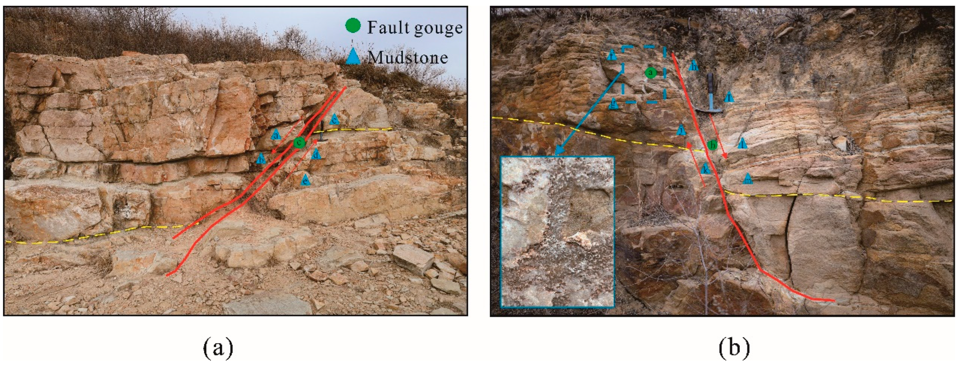
Figure 1. Fault gouge in clastic rocks and sampling locations: (a) infill type; (b) partially cemented type.
Applsci 15 07933 g001
Figure 2. Mineral composition of fault gouge and adjacent mudstone samples collected from the hanging wall and footwall. Note: The sample letters (e.g., A, B, C, ...) correspond to the sampling locations indicated in Figure 1.
Applsci 15 07933 g002
Figure 3. Flow chart of fault gouge direct shear test.
Applsci 15 07933 g003
Figure 4. Shear stress–shear displacement curves of remolded fault gouge.
Applsci 15 07933 g004
Figure 5. Shear strength relationship curves: (a) relationship between shear strength and water content; (b) relationship between shear strength and degree of cementation.
Applsci 15 07933 g005
Figure 6. Cohesion relationship curves: (a) relationship between cohesion and water content; (b) relationship between cohesion and degree of cementation.
Applsci 15 07933 g006
Figure 7. Internal friction angle relationship curves: (a) relationship between internal friction angle and water content; (b) relationship between internal friction angle and cementation degree.
Applsci 15 07933 g007
Figure 8. SEM images of some fault gouge specimens: (a) C0W20; (b) C1W20; (c) C3W10; (d) C3W20; (e) C3W30. Note: Qtz represents quartz particles; Mnt represents montmorillonite particles; Kln represents kaolinite particles; Cs represents cementing substance.
Applsci 15 07933 g008
Figure 9. Correlation between water content and cohesion of fault gouge with different clay contents under various cementation conditions: (a) 0% cementation degree; (b) 1–5% cementation degree (Data source: Wang et al. [28], Qi et al. [31], Kong et al. [41]). Note: wc represents the clay content, and wd represents the degree of cementation.
Applsci 15 07933 g009
Figure 10. Correlation between water content and internal friction angle of fault gouge with different clay contents under various cementation conditions: (a) 0% cementation degree; (b) 1–5% cementation degree (Data source: Wang et al. [28], Qi et al. [31], Kong et al. [41]).
Applsci 15 07933 g010
Figure 11. Relationship between predicted and measured values.
Applsci 15 07933 g011
Table 1. Shear test plan for remolded fault gouge with different cementation degrees and water contents.
SampleCementation Degree (%)Water Content (%)Normal Pressure (kPa)
C0W10010100/200/300/400
C0W1515100/200/300/400
C0W2020100/200/300/400
C0W2525100/200/300/400
C0W3030100/200/300/400
C1W10110100/200/300/400
C1W1515100/200/300/400
C1W2020100/200/300/400
C1W2525100/200/300/400
C1W3030100/200/300/400
C3W10310100/200/300/400
C3W1515100/200/300/400
C3W2020100/200/300/400
C3W2525100/200/300/400
C3W3030100/200/300/400
Note: C0W10—C represents the degree of cementation, and W represents the water content.
Disclaimer/Publisher’s Note: The statements, opinions and data contained in all publications are solely those of the individual author(s) and contributor(s) and not of MDPI and/or the editor(s). MDPI and/or the editor(s) disclaim responsibility for any injury to people or property resulting from any ideas, methods, instructions or products referred to in the content.