Review

Parallels Between Models of Gyrotron Physics and Some Famous Equations Used in Other Scientific Fields

by
Svilen Sabchevski
Institute of Electronics, Bulgarian Academy of Sciences, 1784 Sofia, Bulgaria
Appl. Sci. 2025, 15(14), 7920; https://doi.org/10.3390/app15147920
Submission received: 18 June 2025 / Revised: 8 July 2025 / Accepted: 12 July 2025 / Published: 16 July 2025
(This article belongs to the Section Applied Physics General)

Abstract

In this integrative review paper, we explore the parallels between the physical models of gyrotrons and some equations used in diverse and broad scientific fields. These include Adler’s famous equation, Van der Pol equation, the Lotka–Volterra equations and the Kuramoto model. The paper is written in the form of a pedagogical discourse and aims to provide additional insights into gyrotron physics through analogies and parallels to theoretical approaches used in other fields of research. For the first time, reachability analysis is used in the context of gyrotron physics as a modern tool for understanding the behavior of nonlinear dynamical systems.

1. Introduction

Theoretical models in different scientific disciplines often deal with similar underlying principles or phenomena, albeit from different perspectives. For example, models from physics that describe the behavior of waves can find parallels in biology when examining population dynamics using wave-like patterns of growth and decline. Recognizing these parallels allows scientists to apply insights gained from one field to another, improving our understanding of complex systems. When researchers recognize similarities between models from different fields, this promotes interdisciplinary collaboration. For example, concepts from statistical mechanics can be applied to understand social dynamics in sociology or economics. In other words, models developed in one field can offer valuable insights when applied to another field. This cross-fertilization of ideas encourages innovative approaches to problem-solving and can lead to breakthroughs that would not be possible within the confines of a single discipline. Guided by this conviction, in this paper we explore the parallels between the physical models of gyrotrons and some equations used in diverse and broad scientific fields. These include Adler’s famous equation, Van der Pol’s equation, the Lotka–Volterra equations and the Kuramoto model. An efficient and powerful method for studying and exploring the features of these equations, which we use in this paper, is reachability analysis [1,2,3,4]. Reachability analysis is a fundamental technique in control theory and formal methods that focuses on determining the set of all possible states that a dynamical system can reach from a given set of initial conditions under all admissible inputs and perturbations over a given time horizon (i.e., the time-limit duration over which the analysis is performed). This approach provides a deeper understanding of how a system evolves over time, allowing for better predictions and control strategies. Reachability analysis can also be used to optimize control parameters or design rules to achieve the desired system performance. This makesreachability analysis an important concept in oscillator theory, particularly concerning the behavior of oscillator systems under various conditions.
G.S. Nusinovich was the first to point out that mode interaction, especially the mode competition in the resonant cavity of a gyrotron, is similar to competition between various species in ecology, e.g., the predator–prey dynamics described by the Lotka–Volterra equation [5]. These analogies were then commented on in [6]. In the present paper, we discuss in more detail the parallels between the theoretical models of gyrotron physics and some prominent equations used in other sciences.
Gyro-devices such as gyrotron, gyro-backward oscillator (Gyro-BWO), gyro-traveling wave tube (Gyro-TWT), cyclotron auto-resonance maser (CARM), etc., are powerful sources of coherent electromagnetic radiation in a wide frequency range from millimeter to sub-millimeter wavelengths, which has recently been extended to the terahertz frequencies. They are used in numerous areas of fundamental physics research and in various advanced technologies. Various applications of gyrotrons are described in numerous recent review articles (see e.g., [7,8,9,10,11,12,13,14] and the references therein). The physics of their operation is presented in a large number of publications and monographs (see, e.g., [15,16,17,18,19,20,21,22]). The theory of gyrotrons comprises a rich hierarchy of physical models, beginning with simple analytical, linear, semi-self-consistent models and culminating in those formulated from first principles (Maxwell’s equation for the electromagnetic field combined with relativistic equations of electron motion). These models are implemented in a great number of dedicated problem-oriented, adequate numerical particle-in-cell (PIC) codes (see, for instance, [23,24,25,26,27,28,29,30,31]) that are used for modeling, simulation, computer-aided design (CAD), and optimization of gyrotrons for various applications. The evolution of these models, however, can be traced back to their genesis in some famous equations, which are explored in this paper.
The rest of the paper is organized as follows. In Section 2, we consider Adler’s equation in the context of phase locking and synchronization of gyrotrons. Next, in Section 3, we discuss the Van der Pol equation and its use for analyzing gyrotron oscillators. In Section 4, we explore some parallels between the Kuramoto model of synchronization and some physical mechanisms of gyrotron operation. The parallels between the models of mode interaction in gyrotrons and the models of population dynamics in ecological systems are pointed out in Section 5. Finally, the paper ends with a conclusion in Section 6.

2. Adler’s Equation and Phase Locking and Synchronization of Gyrotrons

For many applications (e.g., thermal processing of materials, plasma heating in fusion devices, etc.), the output parameters of gyrotron radiation that are of interest are the power and frequency, while the coherence and phase stability of the generated microwaves are not essential. In other applications, however, the phase coherence and spectral properties are of critical importance. These include advanced spectroscopic methods such as ESR and DNP-NMR spectroscopy, high-resolution radar imaging and deep-space communication. The latter applications require radiation sources that provide precise amplitude, frequency, and phase in a specified bandwidth with low noise. Phase stability is also a key performance criterion for high-gradient linear accelerators that require multiple phase-locked RF sources to ensure synchronization between the charged particles and the accelerating field.
The pioneering work on the synchronization of gyrotron oscillators was carried out at the Institute of Applied Physics in Gorky, USSR (now Nizhny Novgorod, Russian Federation) [32,33,34,35]. The general theory of synchronization of oscillations in the gyrotron was developed by Ergakov and Moiseev [33]. They analyzed two possible ways of synchronization, namely the use of an external signal injected into the interaction cavity or by pre-bunching the electron beam in an input cavity [34]. Later, they attracted much attention and interest from researchers in the US and other countries around the world [36,37,38,39,40,41]. In recent years, considerable progress has been made both in theory and in the implementation of various concepts for the synchronization of gyrotrons (see, e.g., [42,43,44,45,46,47,48,49,50]).
Over the years, a variety of approaches and sophisticated physical models for the synchronization and locking of gyrotrons have been developed, but they all share a common genealogy, as the idea of phase locking goes back to the seminal work of Robert Adler (best known as the co-inventor of the television remote control [51]), who formulated the famous equation describing the phenomenon of injection locking in nonlinear oscillators [52]. That is why below we discuss the Adler’s relation that was derived initially for oscillators with pentodes before applying it to many other classes of oscillators including the gyrotron.
To begin with, recollect that oscillatory systems are usually susceptible to injection locking or frequency pulling. Injection locking is a nonlinear phenomenon that can be observed in many natural and technical oscillators. It occurs when an oscillator is perturbed by a weak signal whose frequency is close to the free-running frequency of the oscillator. The Adler’s equation that describes the phenomenon of injection locking in nonlinear oscillators and allows us to estimate the frequency range around an oscillator’s natural frequency, where injection locking (syncing to an external signal) occurs, can be written in the following form [51,52]:
d θ d t = Δ ω 0 E 1 E ω 0 2 Q sin θ ,
where θ is the oscillator’s phase, Δ ω 0 = ω 0 ω 1 is the undisturbed beat frequency, ω 0 is the frequency of the free running oscillator, ω 1 and E 1 being the frequency and voltage of the applied signal, respectively, E is the voltage induced in the grid coil, and Q is the the quality factor of the load. Here the ratio E 1 / E is proportional to the square root of the ratio of the the powers of the external (priming) signal and the output signal. This equation is derived for the case when the condition Δ ω 0 ω 0 1 Q is satisfied. If the instantaneous beat frequency d θ d t 0 the oscillator is perturbed but not locked. When the oscillator locks to the external injection signal, the beat frequency vanishes, resulting in the locking condition
sin θ = 2 Q E E 1 Δ ω 0 ω 0 .
Since | sin θ | 1 , the maximum locking range of the oscillator is given by
| Δ ω 0 ω 0 |   < 1 2 Q E 1 E .
Analytical equations (analogous to Adler’s equation) and their solutions for predicting injection locking have been proposed in [53]. This method is very suitable for analyzing the injection-locking phenomenon in LC and ring oscillators because, unlike Adler’s equation, it does not require evaluation of the Q factor. The Adler’s equation can be used to analyze the injection pulling that occurs when the frequency of the injected signal falls slightly out of the lock range. Following [54], this equation can be solved by assuming that | Δ ω 0 |   > [ ω 0 / 2 Q ] ( E 1 / E ) = ω L and noting from Equation (1) that d θ / d t reaches a maximum of Δ ω 0 + ω L , which is a small value compared to ω 0 , i.e., θ varies slowly. Therefore, the Adler’s equation can be written as follows:
d θ Δ ω L sin θ = d t .
Integrating this equation (see [54]) gives
tan θ 2 = ω L Δ ω 0 + ω b Δ ω 0 tan ω b t 2 ,
where ω b = ( Δ ω 0 ) 2 ω L 2 .
Using the notations C = E 1 ω 0 / 2 Q E , α = Δ ω 0 / A , and τ = C t , the Adler’s equation (Equation (1)) can be written in the following dimensionless form:
θ = d θ d τ = α sin θ .
Depending on the value of the parameter α , three cases of phase dynamics are possible, as shown in Figure 1. The black and white circles represent stable and unstable fixed points, respectively. The arrows indicate the direction of the phase change towards or away from the fixed points if they exist. In this illustration, the phase-locked oscillator is represented by Figure 1b. This case is also referred to as entrainment, which is defined by a temporal locking process in which the frequency of one oscillator entrains the frequency of another oscillator. The situation when the oscillators are unlocked is illustrated by the phase portrait in Figure 1c.
Many studies and experimental measurements conclude that the estimation of the locking band roughly agrees with the predictions of Adler’s phase-locking equation (see e.g., [39]). However, in the search for a more accurate analysis, a number of advanced concepts and theoretical models have been developed to describe phase locking in gyrotrons [55]. Although a comprehensive overview of the advances in the implementation of phase locking in gyrotrons is beyond the scope of this article, at least given the limited space we have available here, some notable recent work should be mentioned here at the end of this section.
For example, in [56] it has been shown theoretically that during phase locking of the oscillations of a gyrotron with an output power of two megawatt and a frequency of 170 GHz by a relatively weak external monochromatic signal (about tens of kilowatts), the phase and frequency modulation of the gyrotron radiation due to the low-frequency fluctuations of the accelerating voltage and current decreases severalfold compared to the autonomous regime. This promises to open the way for developing a future complex of coherently radiating megawatt class gyrotrons. The window reflects radiation at the frequency of the operating mode and is transparent for the neighboring modes.
The possibility to stabilize the gyrotron frequency under the influence of a wave reflected from a remote output window during the competition of the operating mode with two neighboring modes, which have frequencies equally spaced from the frequency of the operating mode, has been studied in [57]. In this study, the influence of the shift of the reflector within the limits of several wavelengths on the frequency stabilization is considered. The frequency and phase fluctuations of the radiation caused by low-frequency technical noise of the accelerating voltage of the electron beam are compared in a stand-alone gyrotron and a gyrotron with a reflection.
The first experiments on frequency-locked operation of the 170 GHz/1 MW gyrotron have been reported in [50]. The “driver” gyrotron with a power of 20 kW was equipped with frequency stabilization by means of PLL control of the modulating anode voltage. The radiation was injected into the resonant cavity of the MW gyrotron via the specially designed transmission line and the quasi-optical mode converter for co- and counter-rotating modes. In the experiment, the frequency-locked operation of the 1 MW gyrotron was demonstrated in various operating regimes. The maximum output power was increased to 1.2 MW while the spectral width of the radiation of the powerful gyrotron was reduced to 30 kHz, limited by the pulse duration.
A theory of peer-to-peer locking of high-power gyrotron oscillators coupled with delay and operated in the regime of hard self-excitation that provides maximal efficiency has been presented in [58]. The developed approximate theory of phase locking in the case of a small delay is based on the generalized Adler’s equation, which allows for the treatment of in-phase and anti-phase locking modes. Also, in this paper, a more rigorous bifurcation analysis of phase locking is presented by using XPPAUT software 8.0. The simulations performed by the authors reveal various regimes, including peer-to-peer locking, the suppression of one gyrotron by another, as well as the excitation of one gyrotron by another.
In a recent experimental study [59] of a 170 GHz/1 MW gyrotron locked by a narrowband external signal, an extension of the operating zone by 2.4 times compared to a free-running gyrotron has been demonstrated. The locking signal with a power of less than 16 kW was provided by a gyrotron driver operating in a pulse mode (100 μ s/10 Hz) and stabilized by the phase-lock loop. The observed expansion of the operating zone of the operating mode ( T E 28 , 12 ) into a lower magnetic field region (compared to the free-running regime) was accompanied by an increase in the output power by 10% and the improvement of efficiency from 32.1% to 35.2% The significant expansion of the operating zone in the region of the larger magnetic field demonstrated the suppression of the excitation of parasitic modes. In the frequency-locked regime, the width of the gyrotron radiation spectrum was reduced to 20 kHz, which is defined by the locking signal from the stabilized gyrotron driver, compared to 2–4 MHz in standalone mode. The significance of these results stems from the fact that gyrotron oscillator locking allows for improved mode stability and precise phase and frequency control of the generated millimeter-wave signal.
In experiments for testing a medium-powered 170 GHz gyrotron, developed as a master oscillator for frequency locking of megawatt-level sources, output power of more than 25 kW with about 30% efficiency has been obtained in CW mode. Using a PLL system, the gyrotron frequency has been stabilized, and the spectrum width of less than 2 Hz has been measured, which corresponds to the relative value of about 10 11 [44].
A method providing megawatt-level output power in continuous wave (CW) or long-pulse second-harmonic (SH) gyrotrons using phase-locking by a weak external monochromatic signal has been proposed in [48]. Using a self-consistent multimode model, it was demonstrated that injection of a seeding signal at the operating second-harmonic mode (priming) can suppress the spurious generation at fundamental-harmonic modes during the startup process. The results of numerical simulation demonstrate the applicability of this approach to provide about 1 MW radiation power in a 230 GHz second-harmonic gyrotron with the high-order T E 34 , 14 operating mode, which is generally unattainable for harmonic operation without priming.
In all these studies on phase locking, the legacy of Adler’s equation is evident. Even though more sophisticated models are available today, the Adler’s relation still provides a great deal of insight and is easier to comprehend than its successors. Moreover, its predictions (albeit not precise) can serve as benchmarks when applying more complicated approaches.

3. Van der Pol Equation and the Analysis of Gyrotron Oscillators

Although the Van der Pol equation was initially developed to describe nonlinear oscillators with damping (also known as relaxation oscillators), it is now used in many scientific fields to study a variety of dynamical systems. Its fundamental nature makes it a building block for the development of the theory of various oscillators, including gyrotrons. This equation can be written in the following form [51]:
d 2 F d t 2 μ ( 1 F 2 ) d F d t + F = 0 ,
where F is the amplitude of the oscillating variable (signal), which is a function of time t, and μ is a parameter characterizing the nonlinearity (strength of the damping). For the case μ = 0 (no damping), Equation (7) reduces to the equation of harmonic oscillator. When μ > 0 , all initial conditions converge to a globally unique limit cycle. For electrical limit-cycle circuits (oscillators), there exists a closed trajectory in phase space that has the property that at least one other trajectory spirals into it as time approaches either infinity or negative infinity. When these circuits are driven near the limit cycle, they become entrained, i.e., the driving signal pulls the current along with it. Near the origin d F / d t = 0 , the system is unstable, and far from the origin the system is damped. The numerical integration of the Van der Pol equation is an example of a stiff problem for which certain numerical methods (solvers) are numerically unstable, unless the step size is taken to be extremely small. This complicates its analysis and requires more computing resources.
The qualitative analysis of this equation reveals some general features of the possible solutions [60]. If the solution F > > 1 , both the restoring and damping forces are large, so that | F ( t ) | should decrease with time. In this case the system behaves like a strongly damped oscillator and it disperses energy. On the contrary, if the solution is small | F | < < 1 , the damping force becomes negative, which should make | F ( t ) | tend to increase with time. Between these extreme cases, for typical parameters of the Van der Pol oscillators, as already mentioned, there exists a limit cycle (a unique periodic solution) with a “shape” that strongly depend on μ .
In order to plot the phase-space portrait of the Van der Pol oscillator and to perform the reachability analysis of particular cases with different values of the parameter μ , it is convenient to write this equation in the following two-dimensional form:
F ˙ = y ,
y ˙ = μ ( 1 F 2 ) y F ,
where the dot represents the differentiation with respect to time.
Before continuing the analysis of the above system using an advanced method—reachability analysis—it is instructive to point out that a similar system of equations was derived in [61] (see Equations (58) and (59) in [61]). It describes the pure amplitude interaction between two modes with closely spaced frequencies at the fundamental in the gyrotron cavity by averaging the governing equations of the physical model over fast phase beating. They show that in the case of “strong” coupling between the modes (depending on the initial conditions), the single-mode oscillations of any mode are stable. In the opposite case (“weak” coupling of the modes), when the self-saturation is stronger than the cross-saturation, the two-mode equilibrium is stable. In [62] a model, which describes the excitation of a gyrotron cavity, was developed using the Van der Pol equation. Similar parallels between theory of gyrotrons and Van der Pol oscillators are abundant (see e.g., [5,16,63,64]).
Reachability analysis makes it possible to find out which states a dynamical system can reach starting from a set of initial states and under the influence of a set of input trajectories and parameter values. We apply this approach to the Van der Pol equation to illustrate the form of the data it provides. The following examples were reproduced by us using the excellent open-source Julia ReachabilityAnalysis.jl library [3] and the packages in the JuliaReach [65] ecosystem, which can be used to implement reachability methods for linear, nonlinear, and hybrid ODEs.
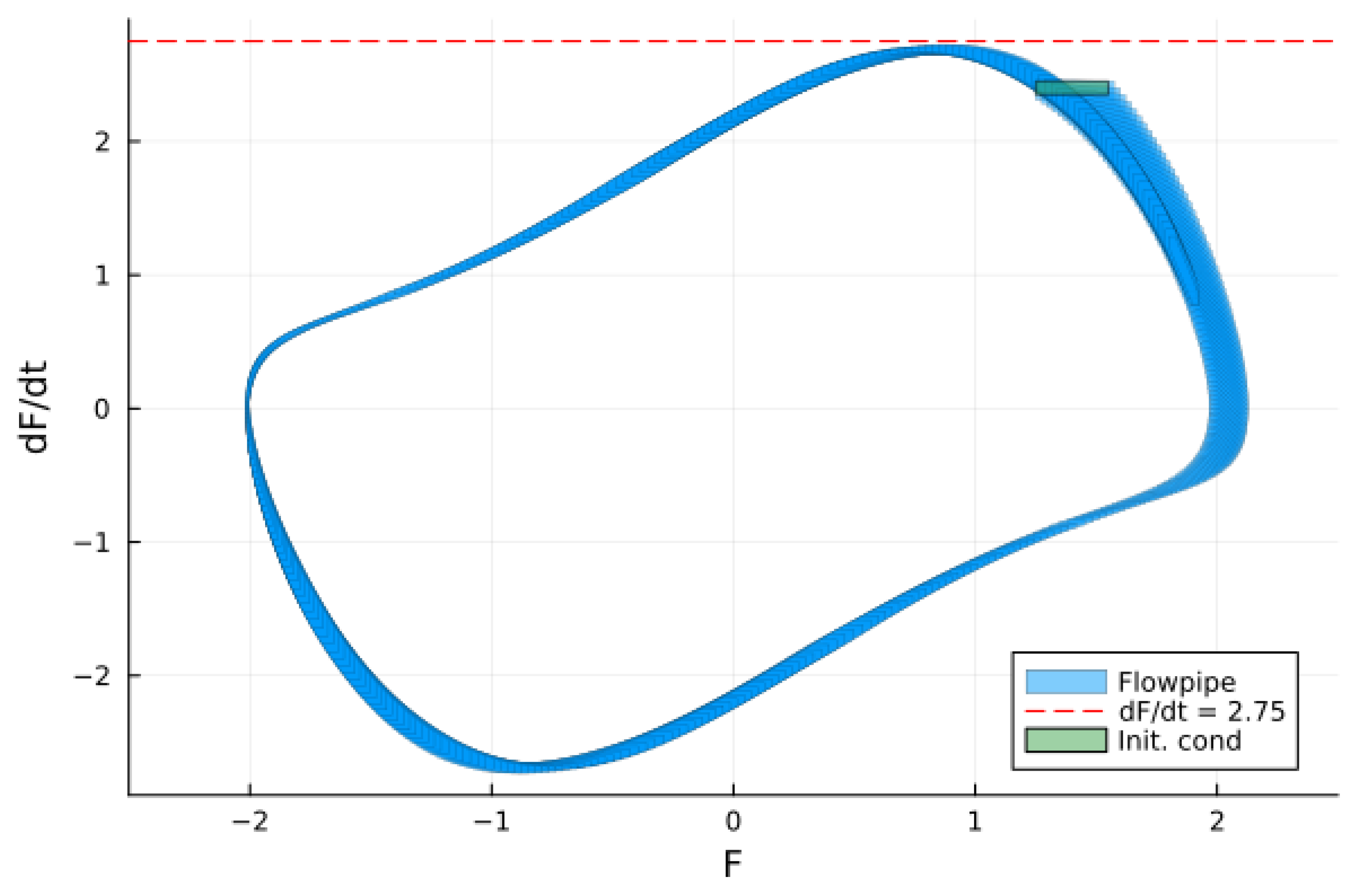
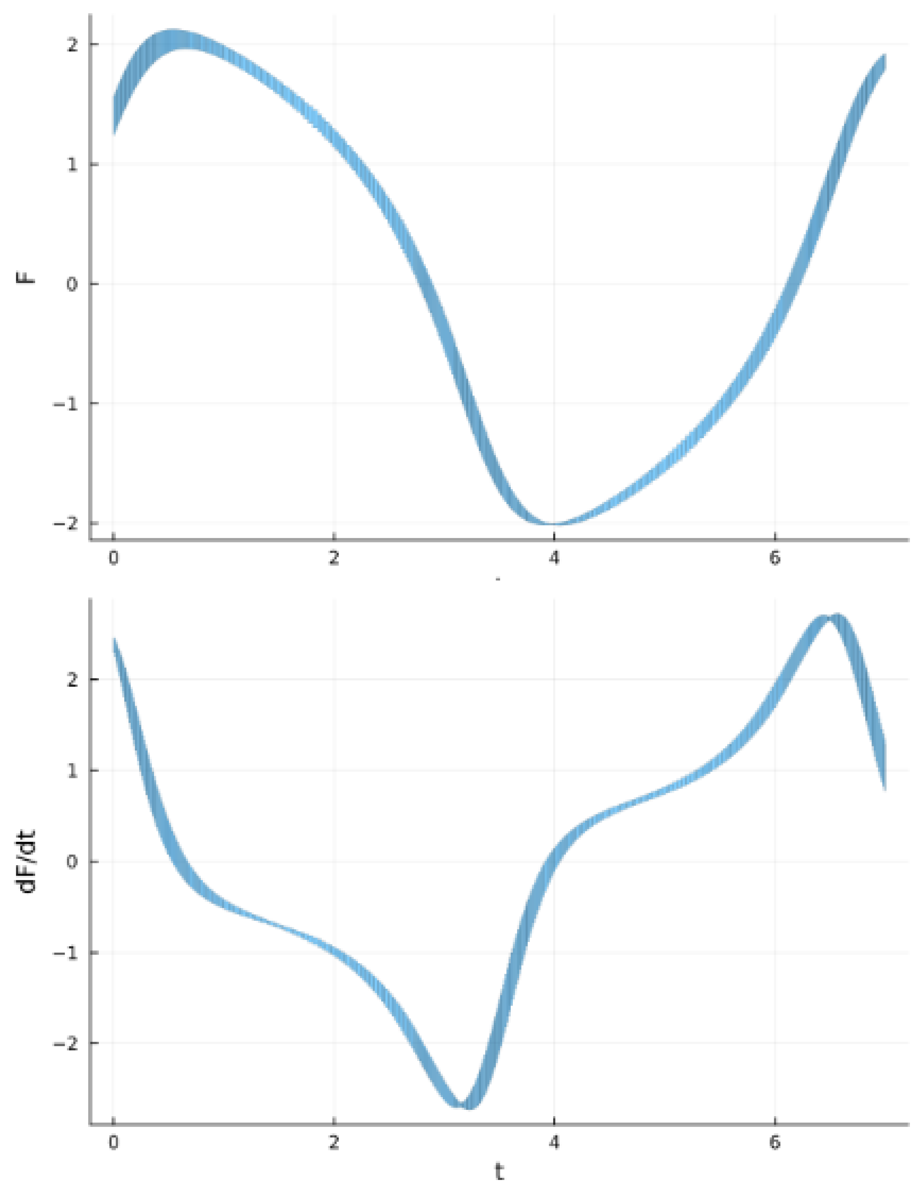
The results of the reachability analysis of the Van der Pol equation are shown in Figure 2, where the flowpipe of the problem is plotted. Recall that the solution obtained by set propagation consists of a flowpipe, which is just an array of reachable sets (reach-sets) and behaves like their set union. Figure 2 proves that there is no solution of the model with a F ˙ value which is greater than 2.75, for any initial condition from the domain selected for this illustrative example (see the caption of Figure 2). The time horizon T = 7 is chosen such that the oscillator can do at least one full cycle. Computing the reachable set allows one to verify that all the behaviors of the closed-loop system stay within a desired range of operation and do not reach a forbidden region of the state space [1]. The corresponding time variation of the state variables F ( t ) and F ˙ ( t ) of the above solution is shown in Figure 3.
The results of the reachability analysis of the Van der Pol oscillator can also be used to examine the existence of an invariant of the system. This is demonstrated in Figure 4, which proves that the flowpipe re-enters from where it started after one loop iteration. It can be seen that the reach set at index 388, corresponding to the time span [6.74967, 6.7599], is included in the union of reach sets with indices from 1 to 13 computed previously. Since all future trajectories starting from the 388th reach set are already covered by the flowpipe; this indicates the presence of an invariant set. In other words, such limit-cycle behavior means that the oscillator tends to converge to a stable limit cycle regardless of the initial conditions. Such a system can generate oscillations without an external periodic driving force due to its inherent nonlinear properties.
The Van der Pol equation can be used to study coupled oscillators. In the case of two such oscillators, the corresponding system is
F ˙ 1 = y 1 ,
y ˙ 1 = μ ( 1 F 1 2 ) y 1 2 F 1 + F 2 ,
F ˙ 2 = y 2 ,
y ˙ 2 = μ ( 1 F 2 2 ) y 2 2 F 2 + F 1 .
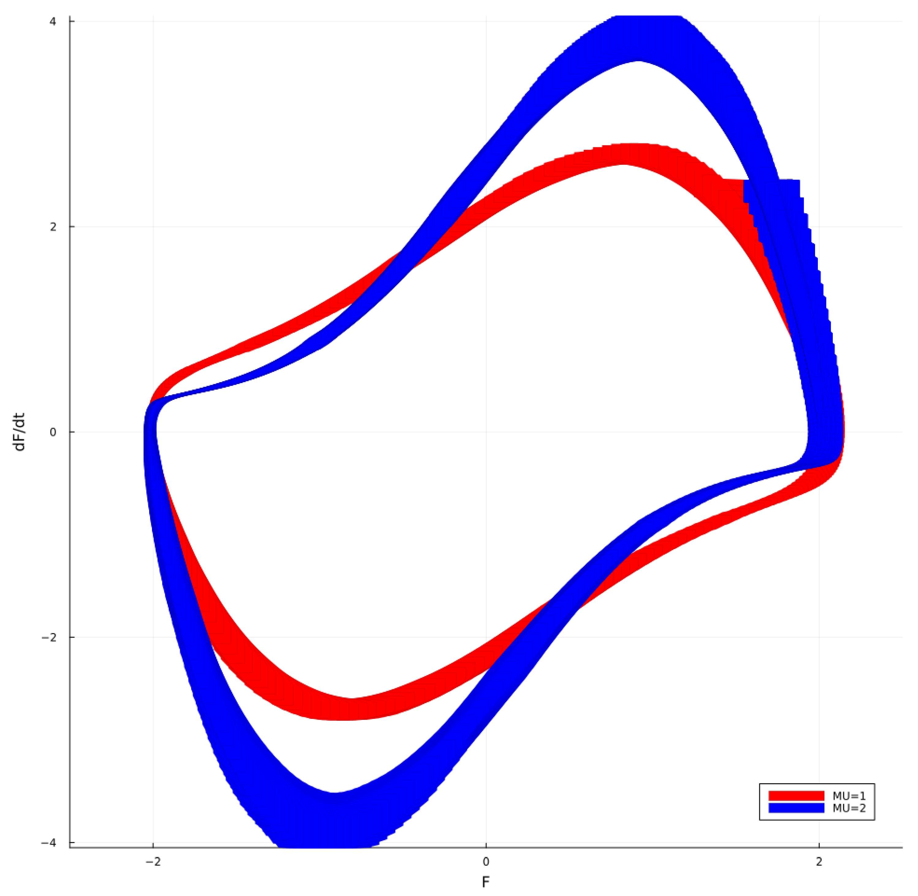
The results of the reachability analysis are shown in Figure 5. The system has a stable limit cycle, which becomes increasingly sharp for higher values of μ . The initial conditions for μ = 1.0 are F 1 , 2 ( 0 ) [ 1.25 ,   1.55 ] and d F 1 , 2 ( 0 ) / d t [ 2.35 ,   2.45 ] . The unsafe set is given by d F 1 , 2 / d t 2.75 in a time horizon of [0, 7]. In the second case ( limit cycle with μ = 2 ), the initial condition is F 1 , 2 ( 0 ) [ 1.55 ,   1.85 ] and d F 1 , 2 ( 0 ) / d t [ 2.35 ,   2.45 ] . The unsafe set is given by d F 1 , 2 / d t 4.05 for a time horizon of [0, 8]. In this case, the time horizon T = 8.0 is used because T = 7.0 is not sufficient for the oscillator to make a complete loop.
Without going into detail (due to the limited space here), it is important to point out that the forced Van der Pol oscillator (in this case, the right-hand side of Equation (7) contains a term corresponding to an external periodic driving force, e.g., A sin ( ω t ) ) exhibits a variety of behaviors, including synchronization, hysteresis, bifurcations, and chaotic dynamics (see e.g., [66,67]). A system of Van der Pol equations is often used for analyzing the interaction between coupled limit-cycle microwave oscillators taking into account the delay [68,69,70]. For example, in [71], a more general equation, namely the Van der Pol–Duffing equation, has been used to study the multistability and complex oscillatory regimes in a microwave generator with delayed reflection from the load. A detailed study of the phase dynamics and computer simulation of coupled Van der Pol and Van der Pol–Duffing oscillators is presented in [72].
The Duffing equation, which is used to model both damped and driven oscillators, is a second-order nonlinear differential equation with cubic nonlinearity of the following type (compare with the Van der Pol equation (Equation (7))):
d 2 F d t 2 δ d F d t + α F + β F 3 = γ cos ( ω t ) ,
where the signal is a function of time F = F ( t ) , δ , α , β and γ being constants (parameters of the model). More precisely, δ controls the amplitude of the damping, while α and β control the linear stiffness and the nonlinearity of the restoring force. Here, γ is the amplitude of the periodic driving force with an angular frequency ω .
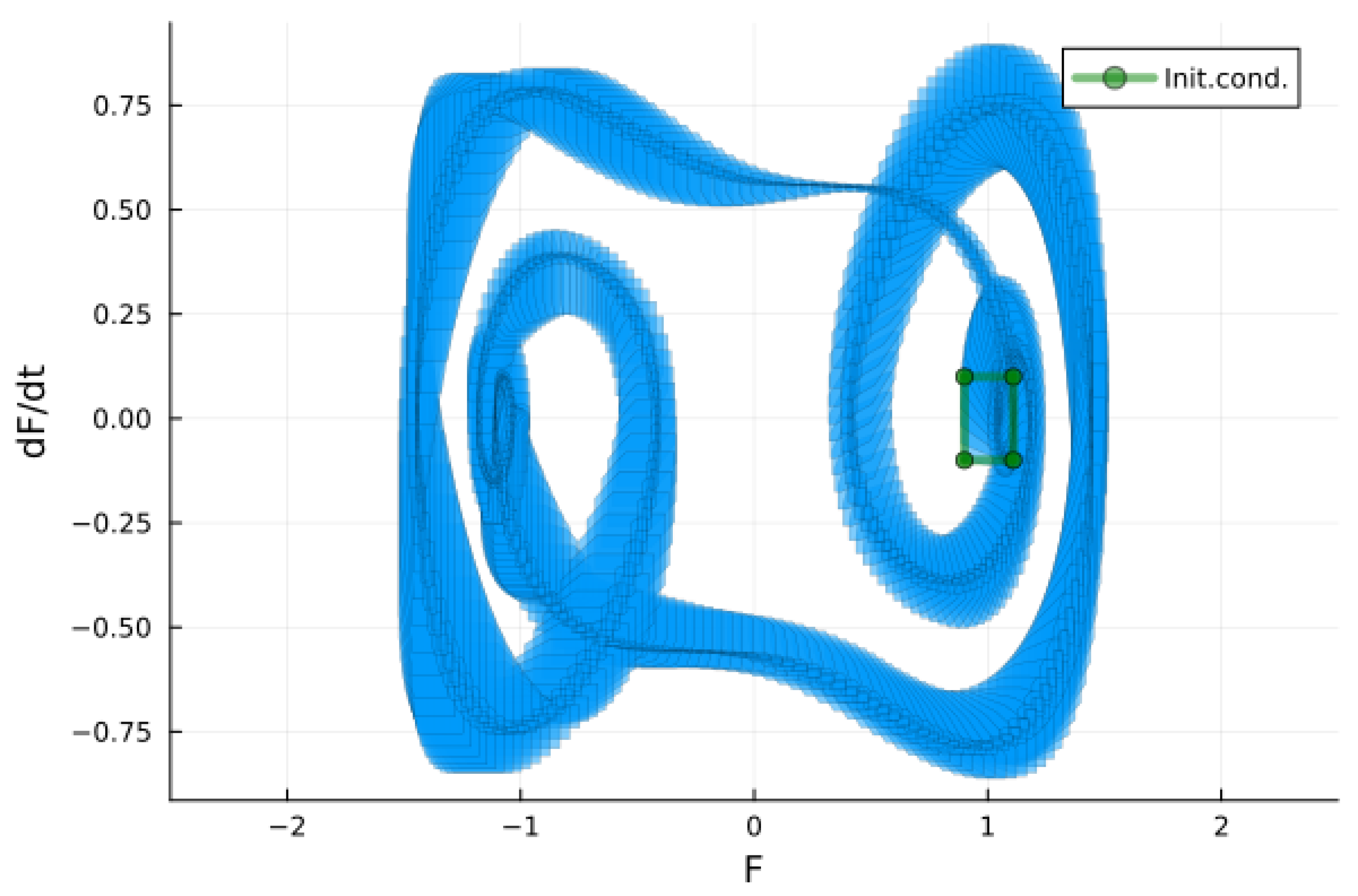
An excellent introduction to Duffing oscillators and their use for modeling a variety of physical processes can be found, for example, in [73]. Here, in Figure 6, we show the results of the reachability analysis of the Duffing equation [4]. Comparing them with those of the Van der Pol equation, it becomes clear that in the latter case the pattern visualizing the set of states is more complex due to the much richer dynamics of the Duffing oscillator.
It is known also that the theory of nonlinear oscillators predicts a double-well potential for certain parameters of the Duffing equation, which allows the simultaneous existence of two steady states. This leads to a hysteresis in which two different amplitudes of the forced oscillation are possible. Depending on the initial state of the system (which can be either at rest or in strong oscillation), the oscillator spontaneously chooses one of the amplitudes when tuning the parameters adiabatically into the hysteretic regime. In addition, small fluctuations can cause unpredictable jumps between the two potential wells and lead to bistability of the oscillation amplitude. A similar behavior has been observed in gyrotron operation, e.g., hysteresis [74,75,76,77], chaotic regimes and bifurcations [78,79,80,81].
If we compare the Adler’s equation (which was considered in the previous section) and the Van der Pol equation, it becomes clear that there are both differences and similarities between them. The Van der Pol oscillators are characterized by the following characteristics: (i) Nonlinear damping, and the damping force depends on the oscillation amplitude (it increases at larger displacements); (ii) Limit cycle behavior; and (iii) Self-excitation. The main features of the Adler’s equation, on the other hand, are the following: (i) The focus is on phase dynamics rather than amplitude and describes how oscillators synchronize with each other; (ii) Coupling mechanism, which is characteristic for the Adler’s oscillator, incorporates interactions between multiple oscillators or external influences that affect their phases; (iii) Synchronization phenomena: It provides insights into how different oscillatory systems can synchronize under certain conditions. Despite their differences, there are notable similarities between these two types of oscillators: (i) Nonlinearity: Both systems exhibit nonlinear behavior leading to complex dynamics not present in linear systems; (ii) Oscillatory nature: Each system generates oscillations that can be analyzed using similar mathematical techniques such as phase space analysis; and (iii) Applications in synchronization: Both types of oscillators have applications in studying synchronization phenomena in various fields such as neuroscience (e.g., neural rhythms), engineering (e.g., circuit design, electronic oscillators), and biology (e.g., population dynamics), to name a few. The above-mentioned differences and similarities between these models make them complementary to each other. In gyrotron theory, the Adler’s equation is a basis for studying phase locking and synchronization [44,48,50,56,57,58,59], while the Van der Pol equation plays a fundamental role as a precursor (archetype) of more specific physical models used to describe and investigate different regimes of gyrotron operation [70,79,80,82,83,84].

4. From the Equations of Adler and Van der Pol to the Kuramoto Model of Synchronization

The relationship between the Adler equation and the Kuramoto model of synchronization, and thus the possibility of building a bridge between their concepts and gyrotron physics, has been briefly pointed out in [6]. In this section, we discuss such a connection in more detail.
Since its formulation, a seemingly simple model of synchronization proposed by Yoshiki Kuramoto [85] in 1974 has demonstrated its potential to describe various phenomena (e.g., synchronous rhythmic flashing of fireflies, pacemaker cells, neurons in the brain, voltage oscillations at a common frequency in an array of current-biased Josephson junctions, phase synchronization in electrical power distribution networks, rhythmic applause and many others [86,87]) in various fields (neuroscience, physics and earth sciences, engineering, etc.) and to introduce a new paradigm in their studies [88,89]. The Kuramoto model is a nonlinear dynamical system of coupled oscillators that initially have random natural frequencies and phases. It shows that if the coupling is strong enough, the system evolves to a state where all oscillators are in phase.
The Kuramoto model is a system of N ordinary differential equations:
d θ i d t = ω i + K N j = 1 N sin ( θ j θ i ) , j = 1 , , N .
Here θ i ( t ) is a real-valued function of time t describing the state (phase) of the i-th oscillator, ω i is the natural (intrinsic) frequency of the i-th oscillator, and K is the strength of the coupling between the oscillators (when K = 0 the equations are linear and the oscillators are independent, ie. θ i ( t ) = ω i t ). The coupling term K is a constant for uniform all-to-all coupling, but in general it can be defined as an N × N adjacency matrix corresponding to other types of coupling, such as uniform, non-uniform, local, unidirectional, self-coupled, etc.
It is easy to draw a parallel between this system and the Adler’s equation (1) considered in Section 2, as they have similar structures, although their terms have different (albeit analogous) meanings. Note that the first term in Equation (1), Δ ω 0 , is the unperturbed beat frequency, while in the Kuramoto equation the first term is the natural frequency ω of a single oscillator. Similarly, the second term of the Adler’s equation is proportional to the strength E 1 of the priming signal, while in Equation (11) it is proportional to the coupling strength K.
An illustration of the dynamics and synchronization of phase-coupled Kuramoto oscillators, created with the open-source software [90], is shown in Figure 7. Graphically the oscillators are represented by points with different angular positions (phases) on a circle. In this example, the selected parameters are the following: the number of oscillators N = 100 and the coupling strength K = 0.5 (in the figure designated by n and k a p p a , respectively). Initially, the phases are distributed uniformly in the interval [ 0 ,   2 π ] and the natural frequencies are distributed uniformly in the interval [ 1 b ,   1 + b ] , where b is a parameter called breadth (see Figure 7a). Another parameter is the “width”. It has no influence on the dynamics and is simply introduced to improve the visibility of the oscillators, because if it is zero, all oscillators are confined to the circle and it is more difficult to see what is happening due to overlapping of the points representing them.
The angular frequencies ω i , which indicate how fast the oscillator moves around the circle, are color-coded, with blue for the fastest, yellow for the slowest, and green in between. When K is increased beyond a critical value (in our example K = 0.50 ), the nonlinear term forces the phases of all oscillators to approach a common limit, as shown in Figure 7b).
A measure of the synchronization between the phases of the oscillators is the order parameter, which is defined as follows:
r e i ψ = 1 N j = 1 N e θ i .
The order parameter r = 0 corresponds to a completely incoherent state, and a finite r corresponds to a certain degree of synchronization. Complete synchronization ( r = 1 ) requires a coupling strength K > K c , where K c is a certain critical value. Combining Equations (11) and (12) gives
d θ i d t = ω i + K r sin ( ψ θ i ) ,
where ψ could be set to 0 since the Kuramoto model is invariant to such a change. Moreover, the latter form of the equation is more suitable for analytical and numerical analysis.
The dynamics and synchronization of Kuramoto oscillators have many features in common with the most essential mechanism of the beam-wave interaction in the gyrotron cavity, namely azimuthal bunching of beam electrons gyrating with cyclotron frequency:
Ω C = e γ m 0 B .
Here e / m 0 is the charge to the rest mass ratio of an electron and γ = ( 1 v 2 c 2 ) 1 / 2 = ( 1 v z 2 + v 2 c 2 ) 1 / 2 is the relativistic Lorentz factor, where v z and v are the axial and transverse components of the total velocity v of the electron, respectively. In light of the Kuramoto model, one could consider the gyrating electrons as oscillators with intrinsic frequencies Ω C i and phases distributed along a circle with a Larmor radius R L .
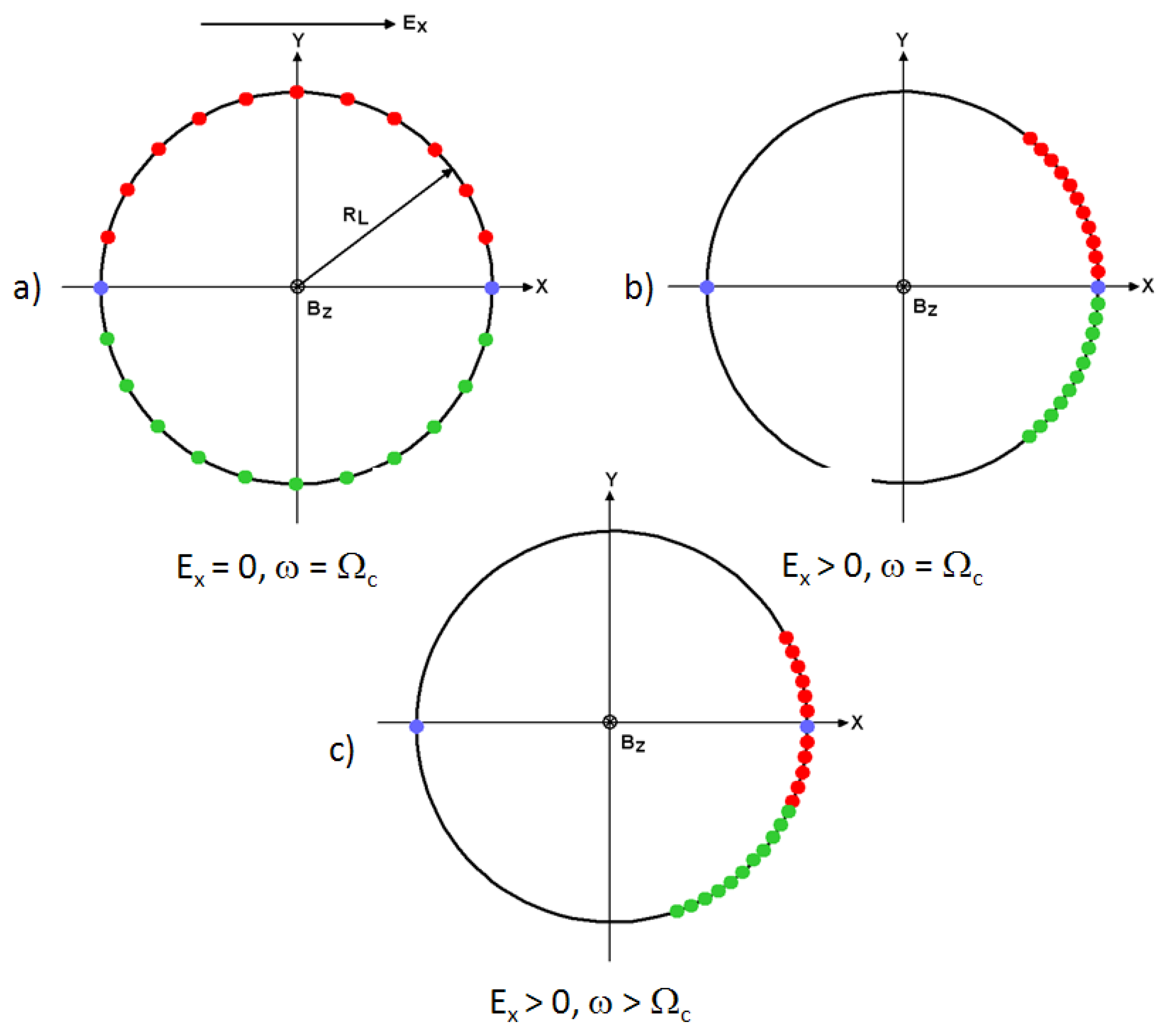
The azimuthal bunching is essential for efficient energy transfer during beam-wave interaction. This mechanism is due to the dependence of the angular frequency of the rotating electrons on their energy, as can be seen in Equation (13). Therefore, when electrons are accelerated by the microwave field, their energy increases and their cyclotron frequency slows down. In contrast, electrons that lose energy and transfer it to the wave increase their cyclotron frequency. As a result, a bunch of electrons is formed, as illustrated in Figure 8 If the cyclotron frequency is equal to the frequency of the cavity mode ( ω = Ω C ), the net equilibrium is zero on average (see Figure 8b). However, when ω > Ω C , the bunch slips towards the decelerating phase (see Figure 8c) and most of the electrons are decelerated, thus transferring energy to the generated radiation. Such a mechanism is realized when the following synchronization condition is maintained:
ω = s Ω C + v z k z ,
where ω is the Doppler-shifted circular frequency of the electromagnetic field, k z is the axial wavenumber, and s = 1 , 2 , 3 , is the harmonic number of the gyrotron operation. The operating point is given by the intersection of the electron beam line (Equation (14)) and the dispersion relation of a certain cavity mode ( TE m , n or TM m , n ) with an eigenwalue χ m , n :
ω 2 = ω c 2 + c 2 k z 2 ,
where ω c = c χ m , n R c is the cut-off frequency and R c is the radius of the resonant cavity.
Another possible application of the Kuramoto model is the study of the interaction of modes in the gyrotron cavity, as pointed out in [6]. In this case, the different modes are considered as phase oscillators with natural frequencies corresponding to the eigenfrequencies of the modes and the coupling strength, which is a function of their starting currents and coupling factors. This work is currently in progress, and its results will be published elsewhere.
A similar approach has been applied in a computer simulation of the dynamic effects of gyrating electrons in a magnetoplasma that lead to to synchronization and phase coherence among the electrons [91].
Recall that in gyrotrons two different regimes of mode interaction are possible, namely amplitude and phase-amplitude interaction [5,92], while the Kuramoto model only describes the phase interaction of coupled oscillators. Therefore, the Kuramoto model is not sufficient in the case of amplitude–phase interaction and should be supplemented by the Stuart–Landau equation [69], which is a generic model that describes the behavior of a nonlinear limit-cycle oscillator near the Hopf (or Andronov–Hopf [46,58,93]) bifurcation. For the amplitude and the phase it gives [94],
d | A | 2 d t = σ r | A | l r 2 | A | 3 ,
and
d ϕ d t = σ i l i 2 | A | 2 ,
where A = | A | e i ϕ is a complex amplitude of the perturbation, σ = σ r + i σ i is the complex growth rate, l = l r + i l i is a complex number, and l r is the Landau constant. The synchronization of two generic oscillators coupled with a delay, namely the Kuramoto oscillator, which only describes the phase dynamics, and the Stuart–Landau oscillator, which includes a variable amplitude, has been investigated in [95].

5. Parallels of the Models of Mode Interaction in Gyrotrons and the Models of Population Dynamics in Ecological Systems

The models of mode interaction in gyrotrons [5,6,96,97] and population dynamics in ecological systems [98,99] share surprising parallels, particularly in how multiple interacting entities can lead to stable or unstable equilibria. Both systems exhibit phenomena like mode competition, multi-mode equilibria, and frequency locking, often governed by similar nonlinear equations. These parallels provide insights into understanding complex systems by drawing analogies between seemingly different domains.
In gyrotrons, multiple modes with similar frequencies can compete for the energy of the electron beam. Similarly, in ecological systems, different species compete for resources such as food, space, and sunlight. Both models describe how the state of the system evolves over time. In gyrotrons, the amplitude and frequency of the different modes change due to interactions. In ecological systems, the population size fluctuates over time due to births, deaths, and interactions with other species. Both the one and the other system can exhibit stable states (single-mode operation in gyrotrons; a stable ecosystem in nature) or chaotic behavior (multimode operation, population collapse). Complex interactions can lead to unpredictable dynamics and chaos. Furthermore, both systems are influenced by positive and negative feedback loops. In gyrotrons, the interaction between the electron beam and the electromagnetic fields can create feedback loops that affect the mode dynamics. In ecological systems, interactions like predation or competition create feedback loops that regulate population sizes. Either of these systems can exhibit emergent properties, meaning that the overall behavior of the system is more than the sum of its individual parts. For example, in a gyrotron, the interaction of multiple modes can lead to new types of instabilities. In ecological systems, the interactions between multiple species can lead to complex ecosystems with unexpected properties.
As an example, following [5,6], we will consider the parallel between the model proposed by G.S. Nusinovich [100], which describes the nonlinear interaction of the amplitudes of two modes, and the Lotka–Volterra equation that describes the relationship between predator and prey populations. In a quasi-linear approximation, if the nonlinear dependence of the gain functions of the modes on their amplitudes can be described by polynomials, the first model is reduced to the following system of equations:
d M 1 d τ = M 1 ( σ 1 β 1 M 1 γ 12 M 2 ) ,
d M 2 d τ = M 2 ( σ 2 + | γ 21 | M 1 + | β 2 | M 2 ν M 2 2 ) ,
where M 1 , 2 are the intensities of the modes. The first equation in this system describes the excitation of the second-harmonic mode, which begins oscillating first, while the following equation represents the mode excitation at the fundamental resonance. The parameters σ 1 , 2 characterize the linear increments of the modes and are proportional to the ratio of the beam current to their starting currents. The other coefficients are influenced by the transit angles, in particular how they relate to the frequency discrepancies with respect to the resonant harmonics of the electron cyclotron frequency multiplied by the time the electrons transit through the cavity. In the study of nonlinear excitation of parasitic modes in harmonic gyrotrons [101,102], these transit angles are such that the first mode falls into a zone of soft excitation. Its saturation is described by the first nonlinear term, while the second mode falls in the region of hard self-excitation. A more complicated nonlinearity accounts for its saturation due to its own intensity. As can be seen, the nonlinear excitation of this mode by the first mode is characterized by the second term in Equation (19a). The coefficient γ 21 representing the cross-saturation effects is negative, indicating that an increase in the intensity of the first mode can incite the excitation of the second mode even if σ 2 < 0 .
The previously mentioned model closely resembles the following system represented by Lotka–Volterra equations, which are commonly used in the field of ecology (see, e.g., [103]) and describes the relationship between populations of predators y and preys x:
d x d t = α x ϵ x 2 β x y ,
d y d t = γ y + δ x y .
Here the prey’s parameters, α and β , describe the maximum prey per capita growth rate, and the effect of the presence of predators on the prey death rate, respectively, while the predator’s parameters, γ , δ describe the predator’s per capita death rate, and the effect of the presence of prey on the predator’s growth rate. The quadratic term in Equation (20a) and its coefficient ϵ are introduced to model more realistic population dynamics, often incorporating effects like Intraspecies competition (where a larger population of one species limits its own growth) or interspecies competition (where one species negatively affects the growth of another).
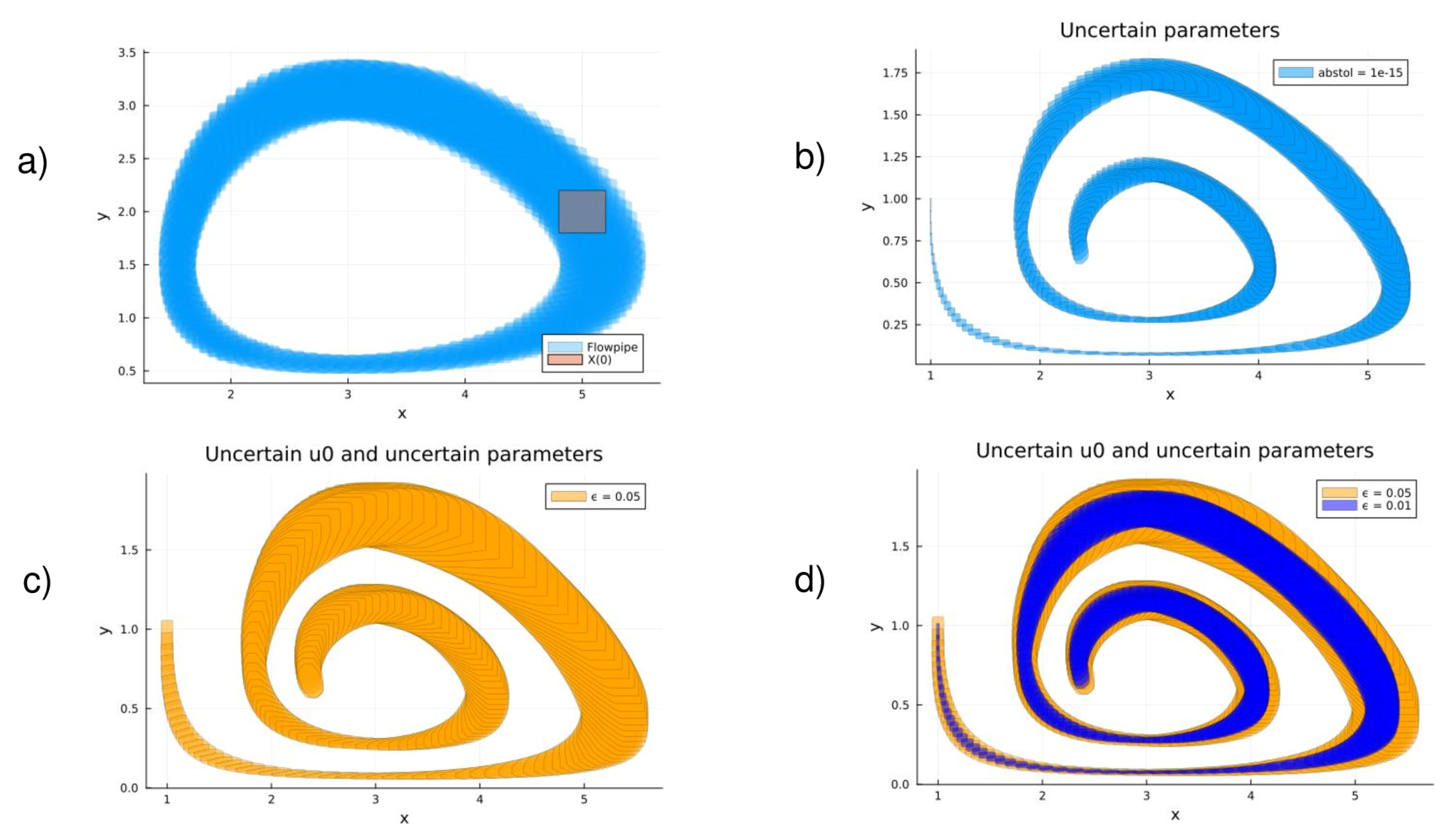
As can be seen, Equation (20a) for the prey population is completely equivalent to Equation (19a) for the first mode’s intensity. In contrast, Equation (20b) is less comprehensive than Equation (19b) because the latter ignores the saturation of predators by its own population. When analyzing the interactions of modes in gyrotrons, these equations, alongside other similar models applied in areas like ecology as well as in epidemiology, economics, neuroscience, and many other domains, result in limit-cycles of the amplitudes in the phase space, as noted by [104]. Without going into details, it should be noted that these equations, although simple, can explain very complex nonlinear dynamics leading to phenomena such as Hopf bifurcation, the transition to chaos, and so on. In order to illustrate the complex dynamics described by the Lotka–Volterra system of equations, some results of the reachability analysis are shown in Figure 9. Figure 9a presents the flowpipe of the solution obtained for given parameters (see the figure caption for details). In this setting, ϵ = 0, i.e., the quadratic nonlinearity is removed. How the solutions change when the quadratic term is included together with the uncertainty of the parameters and the initial conditions, respectively, can be seen in Figure 9b–d.

6. Conclusions

In this integrative review article, we explored a few parallels between models of gyrotron physics and some famous equations used in other scientific fields. These include the equations bearing the names of Adler, Van der Pol, Duffing, Kuramoto, Stuart–Landau, and Lotka–Volterra, and physical models used to study such phenomena as phase locking, synchronization, mode interaction, etc., in gyrotron oscillators. The knowledge of such parallels provides a broader and deeper insight into the physics of gyrotrons and certainly would expand the horizons of the researchers (and especially of the students) working in this field, providing them with additional tools for their studies.
By applying reachability analysis to these equations, we have shown that this powerful method offers several advantages for studying and learning of differential equations. It allows the calculation of the bounds of all possible system trajectories and thus provides comprehensive understanding of the system behavior under different operating conditions. This analysis is particularly useful for the nonlinear systems considered in this paper and those with disturbances and state and input constraints. The visualization of the reachability sets is a kind of “portrait” that shows either the similarities or the differences between the dynamics of the systems under investigation. In other words, reachability analysis provides a complete picture of the potential behavior of the system by determining the set of all reachable states. This is in contrast with traditional methods, which can only focus on specific trajectories or solutions. As far as we know, this efficient and versatile approach is used for the first time in the context of gyrotron physics. It is anticipated that it will find wider applications in the future. In this sense, the current attempt should only be considered as a first step. It should be emphasized that the use of reachability analysis is greatly facilitated by the recent advancements to efficient numerical methods for computing reachable sets and especially the existence of excellent open-source codes and libraries for its implementation, part of which have been used in our study. Furthermore, we hope that this integrative review will motivate many researchers in the gyrotron community to utilize the approaches presented here and thus contribute to the advancement of studies in this field.
It is instructive to conclude the pedagogical discourse of this integrative overview with some further reading recommendations. A deeper understanding of the dynamics of nonlinear oscillators can be gained by studying [60,105,106]. A better insight into the study of their synchronization using the Kuramoto model can be reached by perusing [107,108,109,110]. In addition to the open-source Julia ReachabilityAnalysis.jl library [3] and the packages in the JuliaReach ecosystem [65] used by us, we highly recommend the following advanced course on reachability analysis [111].

Funding

This research received no external funding.

Institutional Review Board Statement

Not applicable.

Informed Consent Statement

Not applicable.

Data Availability Statement

The original contributions presented in the study are included in the article, further inquiries can be directed to the author.

Conflicts of Interest

The authors declare no conflicts of interest.

References

  1. Maler, O. Computing Reachable Sets: An Introduction; French National Center of Scientific Research: Paris, France, 2008; pp. 1–8. Available online: https://www-verimag.imag.fr/~maler/Papers/reach-intro.pdf (accessed on 10 May 2025).
  2. Althoff, M.; Frehse, G.; Girard, A. Set propagation techniques for reachability analysis. Annu. Rev. Control Robot. Auton. Syst. 2021, 4, 369–395. [Google Scholar] [CrossRef]
  3. ReachabilityAnalysis.jl. Methods to Compute Sets of States Reachable by Dynamical Systems. 2025. Available online: https://juliareach.github.io/ReachabilityAnalysis.jl/dev/ (accessed on 10 May 2025).
  4. Bogomolov, S.; Forets, M.; Frehse, G.; Potomkin, K.; Schilling, C. JuliaReach: A toolbox for set-based reachability. In Proceedings of the 22nd ACM International Conference on Hybrid Systems: Computation and Control, Montreal, QC, Canada, 16–18 April 2019; pp. 39–44. [Google Scholar] [CrossRef]
  5. Nusinovich, G. Review of the theory of mode interaction in gyrodevices. IEEE Trans. Plasma Sci. 1999, 27, 313–326. [Google Scholar] [CrossRef]
  6. Sabchevski, S.; Glyavin, M.; Nusinovich, G. The Progress in the Studies of Mode Interaction in Gyrotrons. J. Infrared Millim. Terahertz Waves 2022, 43, 1. [Google Scholar] [CrossRef]
  7. Temkin, R. Development of terahertz gyrotrons for spectroscopy at MIT. Terahertz Sci. Technol. 2014, 7, 1. [Google Scholar] [CrossRef]
  8. Kumar, N.; Singh, U.; Bera, A.; Sinha, A. A review on the sub-THz/THz gyrotrons. Infrared Phys. Technol. 2016, 76, 38. [Google Scholar] [CrossRef]
  9. Glyavin, M.; Sabchevski, S.; Idehara, T.; Mitsudo, S. Gyrotron-Based Technological Systems for Material Processing-Current Status and Prospects. J. Infrared Millim. Terahertz Waves 2020, 41, 1022. [Google Scholar] [CrossRef]
  10. Idehara, T.; Sabchevski, S.; Glyavin, M.; Mitsudo, S. The Gyrotrons as Promising Radiation Sources for THz Sensing and Imaging. Appl. Sci. 2020, 10, 980. [Google Scholar] [CrossRef]
  11. Sabchevski, S.; Glyavin, M.; Mitsudo, S.; Tatematsu, Y.; Idehara, T. Novel and Emerging Applications of the Gyrotrons Worldwide: Current Status and Prospects. J. Infrared Millim. Terahertz Waves 2021, 42, 715. [Google Scholar] [CrossRef]
  12. Litvak, A.G.; Denisov, G.; Glyavin, M. Russian Gyrotrons: Achievements and Trends. IEEE J. Microwaves 2021, 1, 260. [Google Scholar] [CrossRef]
  13. Karmakar, S.; Mudiganti, J. Gyrotron: The Most Suitable Millimeter-Wave Source for Heating of Plasma in Tokamak. In Plasma Science and Technology; IntechOpen: London, UK, 2021. [Google Scholar] [CrossRef]
  14. Sabchevski, S.; Glyavin, M. Development and Application of THz Gyrotrons for Advanced Spectroscopic Methods. Photonics 2023, 10, 189. [Google Scholar] [CrossRef]
  15. Kartikeyan, M.; Borie, E.; Thumm, M. GYROTRONS High Power Microwave and Millimeter Wave Technology; Springer: Berlin/Heidelberg, Germany, 2003. [Google Scholar] [CrossRef]
  16. Nusinovich, G. Introduction to the Physics of Gyrotrons; The Johns Hopkins University Press: Baltimore, MD, USA, 2004. [Google Scholar] [CrossRef]
  17. Chu, K.R. The Electron Cyclotron Maser. Rev. Mod. Phys 2004, 76, 489. [Google Scholar] [CrossRef]
  18. Tsimring, S.E. Electron Beams and Microwave Vacuum Electronics; Wiley-Interscience: Hoboken, NJ, USA, 2007. [Google Scholar]
  19. Du, H.; Du, C.-H.; Liu, P.-K. Millimeter-Wave Gyrotron Traveling-Wave Tube Amplifiers; Springer: Berlin/Heidelberg, Germany, 2014. [Google Scholar]
  20. Gilmour, A.S. Klystrons, Traveling Wave Tubes, Magnetrons, Crossed-Field Amplifiers, and Gyrotrons; Artech House: Norwood, MA, USA, 2011. [Google Scholar]
  21. Grigoriev, A.D.; Ivanov, V.; Molokovsky, S. Microwave Electronics; Springer Series in Advanced Microelectronics; Springer: Berlin/Heidelberg, Germany, 2018; Volume 61. [Google Scholar] [CrossRef]
  22. Dattoli, G.; Palma, E.; Sabchevski, S.; Spassovsky, I. An overview of the gyrotron theory. In High Frequency Sources of Coherent Radiation for Fusion Plasmas; IOP Publishing: Bristol, UK, 2021; p. 51. [Google Scholar] [CrossRef]
  23. Tarakanov, V. Code KARAT Simulations Power Microw. Sources Incl. Cherenkov Plasma Devices, Vircators, Orotron, E-Field Sensor, Calorimeter Etc. EPJ Web Conf. 2017, 149, 04024. [Google Scholar] [CrossRef]
  24. Goplen, B.; Ludeking, L.; Smithe, D.; Warren, G. User-configurable MAGIC for electromagnetic PIC calculations. Comput. Phys. Commun. 1995, 87, 54. [Google Scholar] [CrossRef]
  25. Nguyen, T. Modeling of gyroklystrons with MAGY. IEEE Trans. Plasma Sci. 2000, 28, 867. [Google Scholar] [CrossRef]
  26. Jain, R.; Kartikeyan, M. Design of a 60 GHz, 100 kW CW gyrotron for plasma diagnostics: GDS V.01 simulations. Prog. Electromagn. Res. B 2010, 22, 379. [Google Scholar] [CrossRef]
  27. Sabchevski, S.; Zhelyazkov, I.; Thumm, M.; Illy, S.; Piosczyk, B.; Tran, T.-M.; Pagonakis, J.G. Recent evolution of the simulation tools for computer aided design of electron-optical systems for powerful gyrotrons. Comput. Model. Eng. Sci. 2007, 20, 203. [Google Scholar] [CrossRef]
  28. Sabchevski, S.; Idehara, T.; Saito, T.; Ogaw, I.; Mitsudo, S.; Tatematsu, Y. Physical Models and Computer Codes of the GYROSIM (GYROtron SIMulation) Software Package; FIR Center Report FIR FU-99; IOP Publishing: Bristol, UK, 2010. [Google Scholar]
  29. Braunmueller, F.; Tran, T.; Vuillemin, Q.; Alberti, S.; Genoud, J.; Hogge, J.P.; Tran, M. TWANG-PIC, a novel gyro-averaged onedimensional particle-in-cell code for interpretation of gyrotron experiments. Phys. Plasmas 2015, 22, 063115. [Google Scholar] [CrossRef]
  30. Wang, P.; Chen, X.; Xiao, H.; Dumbrajs, O.; Qi, X.; Li, L. GYROCOMPU: Toolbox Designed for the Analysis of Gyrotron Resonators. IEEE Trans. Plasma Sci. 2020, 48, 3007. [Google Scholar] [CrossRef]
  31. Sawant, A.; Choi, E. Development of the Full Package of Gyrotron Simulation Code. J. Korean Phys. Soc. 2018, 73, 1750. [Google Scholar] [CrossRef]
  32. Belousov, V.l.; Ergakov, V.S.; Moiseev, M.A. Two-cavity CRM at harmonics of electron cyclotron frequency. Electronnaya Tech. Ser. 1 Electron. SVCh 1978, 5, 41–50. [Google Scholar]
  33. Ergakov, V.S.; Moiseev, M.A. Theory of synchronization of oscillations in a cyclotron resonance maser monotron by an external signal. Radiophys. Quantum Electron. 1975, 18, 89–97. [Google Scholar] [CrossRef]
  34. Bazhanov, V.S.; Ergakov, V.S.; Moiseev, M.A. Synchronization of CRM-monotron by by electron beam modulation. Radiophys. Quantum Electron. 1977, 20, 90–95. [Google Scholar] [CrossRef]
  35. Nusinovich, G.S. Efficiency of the mode nonlinear selection methods in CRM-Oscillators. Radio Eng. Electron. Phys. 1977, 22, 151. [Google Scholar]
  36. Read, M.E.; Seeley, R.; Manheimer, W.M. Observations of Phase Locking in a Single-Cavity Gyrotron Oscillator. IEEE Trans. Plasma Sci. 1985, 13, 398–403. [Google Scholar] [CrossRef]
  37. Fliflet, A.W.; Manheimer, W.M. Nonlinear theory of phase-locking gyrotron oscillators driven by an external signal. Phys. Rev. A 1989, 39, 3432–3443. [Google Scholar] [CrossRef] [PubMed]
  38. Latham, P.E.; Granatstein, V.L.; Carmel, Y. Phase locking and bandwidth in a gyrotron oscillator. Int. J. Infrared Millim. Waves 1993, 14, 1217–1227. [Google Scholar] [CrossRef]
  39. Guo, H.; Hoppe, D.; Rodgers, J.; Perez, R.; Tate, J.; Conroy, B.; Granatstein, V.; Bhanji, A.; Latham, P.; Nusinovich, G.; et al. Phase-locking of a second-harmonic gyrotron oscillator using a quasi-optical circulator to separate injection and output signals. IEEE Trans. Plasma Sci. 1995, 23, 822–832. [Google Scholar] [CrossRef]
  40. Rodgers, J.; Guo, H.; Granatstein, V.; Chen, S.; Nusinovich, G.; Walter, M.; Zhao, J. High efficiency, phase-locked operation of the harmonic-multiplying inverted gyrotwystron oscillator. IEEE Trans. Plasma Sci. 1999, 27, 412–421. [Google Scholar] [CrossRef]
  41. Rodgers, J.; Guo, H.; Nusinovich, G.; Granatstein, V. Experimental study of phase deviation and pushing in a frequency doubling, second harmonic gyro-amplifier. IEEE Trans. Electron Devices 2001, 48, 2434–2441. [Google Scholar] [CrossRef]
  42. Glyavin, M.Y.; Denisov, G.; Kulygin, M.; Melnikova, M.; Novozhilova, Y.V.; Ryskin, N. Gyrotron frequency stabilization by a weak reflected wave. Radiophys. Quantum Electron. 2016, 58, 673–683. [Google Scholar] [CrossRef]
  43. Denisov, G.G.; Kuftin, A.N.; Manuilov, V.N.; Zavolsky, N.A.; Chirkov, A.V.; Soluyanova, E.A.; Tai, E.M.; Bakulin, M.I.; Tsvetkov, A.I.; Fokin, A.P.; et al. Design of master oscillator for frequency locking of a complex of megawatt level microwave sources. Microw. Opt. Technol. Lett. 2020, 62, 2137–2143. [Google Scholar] [CrossRef]
  44. Denisov, G.; Kuftin, A.; Glyavin, M.; Tsvetkov, A.; Golubiatnikov, G.; Tai, E.; Soluyanova, E.; Bakulin, M.; Fokin, A.; Shmelev, M.; et al. Experimental tests of a high-stable 170 GHz/25 kW gyrotron as a master oscillator for frequency locking of megawatt level microwave sources. In Proceedings of the 2021 22nd International Vacuum Electronics Conference (IVEC), Rotterdam, The Netherlands, 27–30 April 2021; pp. 1–2. [Google Scholar] [CrossRef]
  45. Krier, L.; Avramidis, K.A.; Braune, H.; Gantenbein, G.; Illy, S.; Ioannidis, Z.; Jelonnek, J.; Laqua, H.P.; Marsen, S.; Moseev, D.; et al. Frequency Stabilization of Megawatt-Class 140 GHz Gyrotrons at W7-X Using an Off-the-Shelf PLL System. In Proceedings of the 2021 46th International Conference on Infrared, Millimeter and Terahertz Waves (IRMMW-THz), Chengdu, China, 29 August–3 September 2021; pp. 1–2. [Google Scholar] [CrossRef]
  46. Grigorieva, N.V.; Ryskin, N.M. A study of gyrotron synchronization in the hard-excitation regime on the basis of the modified quasilinear model. Radiophys. Quantum Electron. 2022, 65, 371–383. [Google Scholar] [CrossRef]
  47. Adilova, A.B.; Ryskin, N.M. The phase-locking of high-power delay-coupled gyrotron oscillators with hard excitation. In Proceedings of the 2022 IEEE 8th All-Russian Microwave Conference (RMC), Moscow, Russia, 23–25 November 2022. [Google Scholar] [CrossRef]
  48. Denisov, G.G.; Zotova, I.V.; Zheleznov, I.V.; Malkin, A.M.; Ginzburg, N.S.; Sergeev, A.S.; Semenov, E.S.; Glyavin, M.Y. Phase-Locking of Second-Harmonic Gyrotrons for Providing MW-Level Output Power. IEEE Trans. Electron Devices 2022, 69, 754–758. [Google Scholar] [CrossRef]
  49. Rozental, R.M.; Zotova, I.V.; Sergeev, A.S.; Ginzburg, N.S.; Denisov, G.G. Concept of Gyrotron Complexes With Serial Phase and Frequency Locking. IEEE Trans. Electron Devices 2023, 70, 2161–2164. [Google Scholar] [CrossRef]
  50. Fokin, A.P.; Kuftin, A.N.; Belousov, V.I.; Chirkov, A.V.; Shmelev, M.Y.; Golubiatnikov, G.Y.; Movshevich, B.Z.; Tai, E.M.; Glyavin, M.Y.; Denisov, G.G. First Experiments on Frequency Locked Operation of the 170 GHz/1 MW Gyrotron. In Proceedings of the 2024 Photonics and Electromagnetics Research Symposium (PIERS), Chengdu, China, 21–25 April 2024; pp. 1–6. [Google Scholar] [CrossRef]
  51. Acebrón, J.A.; Spigler, R. The Remote Control and Beyond: The Legacy of Robert Adler. SIAM News 2007, 40, 613. [Google Scholar]
  52. Adler, R. A Study of Locking Phenomena in Oscillators. Proc. IRE 1946, 34, 351–357. [Google Scholar] [CrossRef]
  53. Lai, X.; Roychowdhury, J. Analytical equations for predicting injection locking in LC and ring oscillators. In Proceedings of the IEEE 2005 Custom Integrated Circuits Conference, San Jose, CA, USA, 21 September 2005; pp. 461–464. [Google Scholar] [CrossRef]
  54. Razavi, B. A study of injection pulling and locking in oscillators. In Proceedings of the IEEE 2003 Custom Integrated Circuits Conference, San Jose, CA, USA, 24 September 2003; pp. 305–312. [Google Scholar] [CrossRef]
  55. Nusinovich, G.S.; Dumbrajs, O. Technical noise in gyroklystrons and phase-locked gyrotron oscillators. Phys. Plasmas 1997, 4, 1424–1433. [Google Scholar] [CrossRef]
  56. Bakunin, V.L.; Denisov, G.G.; Novozhilova, Y.V. Phase locking of a gyrotron with low-frequency voltage and current fluctuations by an external monochromatic signal. Radiophys. Quantum Electron. 2020, 63, 392–402. [Google Scholar] [CrossRef]
  57. Bakunin, V.L.; Denisov, G.G.; Kuftin, A.N.; Novozhilova, Y.V.; Fokin, A.P.; Zuev, A.S.; Semenov, E.S. Stabilization of the radiation frequency of a gyrotron with a remote reflector under the conditions of interaction of the equidistant-spectrum modes. Radiophys. Quantum Electron. 2023, 65, 566–577. [Google Scholar] [CrossRef]
  58. Adilova, A.B.; Ryskin, N.M. Theory of Peer-to-Peer Locking of High-Power Gyrotron Oscillators Coupled with Delay. Electronics 2022, 11, 811. [Google Scholar] [CrossRef]
  59. Kuftin, A.N.; Golubiatnikov, G.Y.; Vilkov, V.A.; Fokin, A.P.; Novozhilova, Y.V.; Glyavin, M.Y.; Denisov, G.G. Experimental Study of Extended Operating Zone of a 170-GHz/1-MW Gyrotron Locked by a Narrowband External Signal. IEEE Trans. Electron Devices 2024, 71, 7061–7065. [Google Scholar] [CrossRef]
  60. Gaponov-Grekhov, A.V.; Rabinovich, M.I. L. I. Mandel’shtam and the modern theory of nonlinear oscillations and waves. Sov. Phys. Uspekhi 1979, 22, 590. [Google Scholar] [CrossRef]
  61. Nusinovich, G.S. To the theory of gyrotrons with confocal resonators. Phys. Plasmas 2019, 26, 053107. [Google Scholar] [CrossRef]
  62. Barroso, J.J. Cavity Excitation Described by the van der Pol Equation in Transit-Time Tubes. IEEE Trans. Electron Devices 2007, 54, 3085–3091. [Google Scholar] [CrossRef]
  63. Ryskin, N.M.; Shigaev, A.M. Complex dynamics of a simple distributed self-oscillatory model system with delay. Tech. Phys. 2002, 47, 795–802. [Google Scholar] [CrossRef]
  64. Koronovsky, A.A.; Trubetskov, D.I.; Khramov, A.E. Transient Processes in the Distributed Active Medium “Helical Electron Beam–Counterpropagating Electromagnetic Wave”. Radiophys. Quantum Electron. 2004, 47, 332–340. [Google Scholar] [CrossRef]
  65. Reachability Computations for Dynamical Systems in Julia. 2025. Available online: https://github.com/juliareach (accessed on 10 May 2025).
  66. Mathematica Tutorial for the Second Course. Part III: Van der Pol Equations. 2025. Available online: https://www.cfm.brown.edu/people/dobrush/am34/Mathematica/ch3/pol.html (accessed on 10 May 2025).
  67. Kanamaru, T. Van der Pol oscillator. Sch. J. 2007, 2, 2202. [Google Scholar] [CrossRef]
  68. Lynch, J.; York, R. Stability of mode locked states of coupled oscillator arrays. IEEE Trans. Circuits Syst. I Fundam. Theory Appl. 1995, 42, 413–418. [Google Scholar] [CrossRef]
  69. Wirkus, S.; Rand, R. The Dynamics of Two Coupled van der Pol Oscillators with Delay Coupling. Nonlinear Dyn. 2002, 30, 205–221. [Google Scholar] [CrossRef]
  70. Balakin, M.I.; Ryskin, N.M. Bifurcational mechanism of formation of developed multistability in a van der Pol oscillator with time-delayed feedback. Nelineinaya Din. 2017, 13, 151–164. [Google Scholar] [CrossRef]
  71. Balakin, M.I.; Ryskin, N.M. Multistability and complex oscillatory regimes in a microwave generator with delayed reflection from the load. Tech. Phys. Lett. 2019, 45, 278–280. [Google Scholar] [CrossRef]
  72. Kuznetsov, A.P.; Stankevich, N.V.; Turukina, L.V. Coupled Van der Pol and Van der Pol–Duffing oscillators: Dynamics of Phase and Computer Simulation. Izv. VUZ 2008, 16, 101–136. [Google Scholar] [CrossRef]
  73. Korsch, H.J.; Jodl, H.J.; Hartmann, T. The duffing oscillator. In Chaos; Springer: Berlin/Heidelberg, Germany, 2008; pp. 157–184. [Google Scholar]
  74. Brand, G.F.; Ideharaj, T.; Tatsukawa, T.; Ogawa, I. Mode competition in a high harmonic gyrotron. Int. J. Electron. 1992, 72, 745–758. [Google Scholar] [CrossRef]
  75. Dumbrajs, O.; Idehara, T.; Iwata, Y.; Mitsudo, S.; Ogawa, I.; Piosczyk, B. Hysteresis in gyrotrons. In Proceedings of the Twenty Seventh International Conference on Infrared and Millimeter Waves, San Diego, CA, USA, 26 September 2002; pp. 331–332. [Google Scholar] [CrossRef]
  76. Dumbrajs, O.; Idehara, T.; Iwata, Y.; Mitsudo, S.; Ogawa, I.; Piosczyk, B. Hysteresis-like effects in gyrotron oscillators. Phys. Plasmas 2003, 10, 1183–1186. [Google Scholar] [CrossRef]
  77. Dumbrajs, O.; Khutoryan, E.M.; Idehara, T. Hysteresis and frequency tunability of gyrotrons. J. Infrared Millim. Terahertz Waves 2016, 37, 551–560. [Google Scholar] [CrossRef]
  78. Blokhina, E.V.; Rozhnev, A.G. Chaos and hyperchaos in a gyrotron. Radiophys. Quantum Electron. 2006, 49, 799–810. [Google Scholar] [CrossRef]
  79. Nusinovich, G.S.; Sinitsyn, O.V. Interpretation of the nonlinear mode excitation in the ITER gyrotron. Phys. Plasmas 2007, 14, 113103. [Google Scholar] [CrossRef]
  80. Blokhina, E.V.; Kuznetsov, S.P.; Rozhnev, A.G. High-Dimensional Chaos in a Gyrotron. IEEE Trans. Electron Devices 2007, 54, 188–193. [Google Scholar] [CrossRef]
  81. Fedotov, A.E.; Rozental, R.M.; Isaeva, O.B.; Rozhnev, A.G. Chaos and Hyperchaos in a Ka-Band Gyrotron. IEEE Electron Device Lett. 2021, 42, 1073–1076. [Google Scholar] [CrossRef]
  82. Ishchenko, A.S.; Novozhilova, Y.V.; Petelin, M.I. Theory of locking of a Van der Pol oscillator by delayed reflection from a resonant load. Radiophys. Quantum Electron. 2006, 49, 485–498. [Google Scholar] [CrossRef]
  83. Usacheva, S.A.; Ryskin, N.M. Phase locking of two limit cycle oscillators with delay coupling. Chaos 2014, 24, 023123. [Google Scholar] [CrossRef] [PubMed]
  84. Rozental, R.M.; Ginzburg, N.S.; Glyavin, M.Y.; Sergeev, A.S.; Zotova, I.V. Mutual synchronization of weakly coupled gyrotrons. Phys. Plasmas 2015, 22, 093118. [Google Scholar] [CrossRef]
  85. Kuramoto, Y. Self-entrainment of a population of coupled non-linear oscillators. In International Symposium on Mathematical Problems in Theoretical Physics; Springer: Berlin/Heidelberg, Germany, 1975; pp. 420–422. [Google Scholar] [CrossRef]
  86. Kuramoto, Y. Phase- and Center-Manifold Reductions for Large Populations of Coupled Oscillators with Application to Non-Locally Coupled Systems. Int. J. Bifurc. Chaos 1997, 07, 789–805. [Google Scholar] [CrossRef]
  87. Strogatz, S.H. Sync: How Order Emerges from Chaos in the Universe, Nature, and Daily Life, 1st ed.; Hyperion: New York, NY, USA, 2003. [Google Scholar]
  88. Acebrón, J.A.; Bonilla, L.L.; Pérez Vicente, C.J.; Ritort, F.; Spigler, R. The Kuramoto model: A simple paradigm for synchronization phenomena. Rev. Mod. Phys. 2005, 77, 137–185. [Google Scholar] [CrossRef]
  89. Rosenblum, M.; Pikovsky, A. Synchronization: From pendulum clocks to chaotic lasers and chemical oscillators. Contemp. Phys. 2003, 44, 401–416. [Google Scholar] [CrossRef]
  90. Dirk Brockman and Steven Strogatz, “Ride My Kuramoto Cycle”. 2025. Available online: https://www.complexity-explorables.org/explorables/ride-my-kuramotocycle (accessed on 10 May 2025).
  91. Subbarao, D.; Arora, M.; Uma, R.; Phanendra, M.V.R.; Singh, K.K. Computer simulation of gyrophase self-organisation in a magnetoplasma. Comput. Phys. Commun. 2004, 164, 477–481. [Google Scholar] [CrossRef]
  92. Zapevalov, V.E.; Nusinovich, G.S. The theory of amplitude-phase mode interactions in electron masers. Radiophys. Quantum Electron. 1989, 32, 269–276. [Google Scholar] [CrossRef]
  93. Adilova, A.B.; Balakin, M.I.; Gerasimova, S.A.; Ryskin, N.M. Bifurcation analysis of multistability of synchronous states in the system of two delay-coupled oscillators. Chaos Interdiscip. J. Nonlinear Sci. 2021, 31, 113103. [Google Scholar] [CrossRef] [PubMed]
  94. Provansal, M.; Mathis, C.; Boyer, L. Bénard-von Kármán instability: Transient and forced regimes. J. Fluid Mech. 1987, 182, 1. [Google Scholar] [CrossRef]
  95. D’Huys, O.; Vicente, R.; Danckaert, J.; Fischer, I. Amplitude and phase effects on the synchronization of delay-coupled oscillators. Chaos Interdiscip. J. Nonlinear Sci. 2010, 20, 043127. [Google Scholar] [CrossRef] [PubMed]
  96. Nusinovich, G.S. Mode interaction in gyrotrons. Int. J. Electron. 1981, 51, 457–474. [Google Scholar] [CrossRef]
  97. Zavol’skii, N.A.; Nusinovich, G.S. Interaction of modes in gyrotrons with a high-frequency field whose longitudinal structure is variable. Radiophys. Quantum Electron. 1990, 33, 627–632. [Google Scholar] [CrossRef]
  98. Wangersky, P.J. Lotka-Volterra Population Models. Annu. Rev. Ecol. Syst. 1978, 9, 189–218. [Google Scholar] [CrossRef]
  99. Berryman, A.A. The Orgins and Evolution of Predator-Prey Theory. Ecology 1992, 73, 1530–1535. [Google Scholar] [CrossRef]
  100. Nusinovich, G. Mode competition in a gyromonotron with a distorted axial symmetry. Radiotekhnika I Elektron. 1974, 19, 1788–1790. [Google Scholar]
  101. Gashturi, A.P.; Nusinovich, G.S.; Zotova, I.V.; Semenov, E.S.; Sabchevski, S.P.; Glyavin, M.Y. Nonlinear excitation of parasitic modes in harmonic gyrotrons. Phys. Plasmas 2020, 27, 063304. [Google Scholar] [CrossRef]
  102. Sabchevski, S.; Nusinovich, G.; Glyavin, M. Harmonic Gyrotrons: Pros and Cons. J. Infrared Millim. Terahertz Waves 2024, 45, 184–207. [Google Scholar] [CrossRef]
  103. Maynard-Smith, J. Models in Ecology; Cambridge University Press: Cambridge, UK, 1974. [Google Scholar]
  104. Nusinovich, G. Methods of voltage feeds for a pulsed gyromonotron which ensure high-efficiency in a single-mode operation. Elektron. Teknh. Elektron. SVCh 1974, 3, 44–49. [Google Scholar]
  105. Ginoux, J.M. History of Nonlinear Oscillations Theory in France (1880–1940); Springer: Berlin/Heidelberg, Germany, 2017; Volume 49. [Google Scholar]
  106. Landa, P.S. Nonlinear Oscillations and Waves in Dynamical Systems; Springer: Berlin/Heidelberg, Germany, 2013; Volume 360. [Google Scholar]
  107. Pikovsky, A.; Rosenblum, M.; Kurths, J.; Synchronization, A. A Universal Concept in Nonlinear Sciences; Cambridge University Press: Princeton, NJ, USA, 1985. [Google Scholar]
  108. Strogatz, S.H. From Kuramoto to Crawford: Exploring the onset of synchronization in populations of coupled oscillators. Phys. D Nonlinear Phenom. 2000, 143, 1–20. [Google Scholar] [CrossRef]
  109. Strogatz, S.H. Sync: How Order Emerges from Chaos in the Universe, Nature, and Daily Life; Grand Central Publishing: New York, NY, USA, 2012. [Google Scholar]
  110. Spigler, R. The mathematics of Kuramoto models which describe synchronization phenomena. Mat. Cult. E Società. Riv. Dell’Unione Mat. Ital. 2016, 1, 123–132. [Google Scholar]
  111. JuliaReach—Summer of Code. 2025. Available online: https://julialang.org/jsoc/gsoc/juliareach/ (accessed on 10 May 2025).
Figure 1. Phase dynamics: (a) Free running and priming oscillators have the same frequency (synchrony); (b) the oscillators are phase locked (also called phase entrainment), and there is a stable and constant phase difference; (c) the oscillators are unlocked (phase drift ).
Applsci 15 07920 g001
Figure 2. Results of the reachability analysis of the Van der Pol equation for μ = 1 . Shown are the flowpipe and the region of the initial conditions F ( 0 ) [ 1.25 ,   1.55 ] ,   F ˙ ( 0 ) [ 2.35 ,   2.45 ] . The unsafe set is given by F ˙ 2.75 for a time span [0, 7].
Applsci 15 07920 g002
Figure 3. State variables as functions of time that correspond to Figure 2: F ( t ) and F ˙ ( t ) .
Applsci 15 07920 g003
Figure 4. Examining the existence of an invariant of the system. The solution is calculated for the parameters and initial conditions of Figure 2.
Applsci 15 07920 g004
Figure 5. Reachability analysis of two coupled Van der Pol oscillators. The set of initial states for μ = 1.0 are F 1 , 2 ( 0 ) [ 1.25 ,   1.55 ] and d F 1 , 2 ( 0 ) / d t [ 2.35 ,   2.45 ] . The limit cycle with μ = 2 (blue color) is calculated for the initial conditions F 1 , 2 ( 0 ) [ 1.55 ,   1.85 ] and d F 1 , 2 ( 0 ) / d t [2.35, 2.45].
Applsci 15 07920 g005
Figure 6. Results of the reachability analysis of the Duffing equation performed for the following parameters: ω = 1.2 , α = 1.0 , β = 1.0 , δ = 0.3 and γ = 0.37 . Visualized is the set of states reachable by the Duffing oscillator starting from any initial condition with position in the interval ( 0.9 ÷ 1.1 ) for F and in the interval ( 0.1 ÷ 0.1 ) for d F / d t . The region occupied by the initial conditions is encircled by a green line. The time span is ( 0 ÷ 20 T ) , where T = 2 π / ω .
Applsci 15 07920 g006
Figure 7. Dynamics and synchronization of Kuramoto oscillators illustrated: (a) initial distribution by phases; (b) final state of oscillators [90].
Applsci 15 07920 g007
Figure 8. Azimuthal bunching of electrons gyrating in the gyrotron cavity at cyclotron frequency and interacting with the high-frequency electromagnetic field E x of an operating mode with a frequency of ω . (a) Initial uniform distribution of electrons by phase. (b) Bunching of electrons when ω = Ω C . (c) Slippage of the formed bunch in the direction of the decelerating phase when ω > Ω C .
Applsci 15 07920 g008
Figure 9. Results of the reachability analysis of the system of Lotka–Volterra equations: (a) Flowpipe of the solution obtained for the following parameters: α = 1.5, β = 1.0, γ = 3.0, δ = 1.0. In this setting ϵ = 0, i.e., the quadratic nonlinearity is removed. The initial set X ( 0 ) is x [ 4.8 ,   5.2 ] and y [ 1.8 ,   2.2 ] . (b) The solution when an additional term ϵ x 2 is added to the right-hand side of the first differential equation and the parameters are uncertain model constants ( α , β , γ , δ , and ϵ are uncertain in the intervals (0.99 … 1.01), (0.99 … 1.01), (2.99 … 3.01), (0.99 … 1.01), and (0.099 … 0.101), respectively) that define the uncertain set u0. (c) In this setting, the uncertain parameter ϵ with radius 0.05 is considered. (d) In this setting, the uncertain parameter ϵ with radius 0.01 is added.
Applsci 15 07920 g009
Disclaimer/Publisher’s Note: The statements, opinions and data contained in all publications are solely those of the individual author(s) and contributor(s) and not of MDPI and/or the editor(s). MDPI and/or the editor(s) disclaim responsibility for any injury to people or property resulting from any ideas, methods, instructions or products referred to in the content.