Abstract
The escalating heat flux densities in high-performance electronics necessitate superior thermal management. This study enhanced pool-boiling heat transfer, a method offering high heat removal capacity, by leveraging Binder Jetting 3D Printing (BJ3DP) to create complex porous copper structures without the need for chemical treatments. This approach enables a reliable utilization of phenomena like capillarity for improved performance. Three types of porous copper structures, namely Large Lattice, Small Lattice, and Staggered, were fabricated on pure copper substrates and tested via pool boiling of de-ionized and de-gassed water at atmospheric pressure. Compared to a plain polished copper surface, which exhibited a critical heat flux (CHF) of 782 kW/m2 at a wall superheat of 18 K, the 3D-printed porous copper surfaces showed significantly improved heat transfer performance. The Staggered surface achieved a conventional CHF of 2342.4 kW/m2 (a 199.7% enhancement) at a wall superheat of 24.6 K. Notably, the Large Lattice and Small Lattice structures demonstrated exceptionally stable boiling without reaching the typical catastrophic CHF within the experimental parameters. These geometries continued to increase in heat flux, reaching maximums of 2397.7 kW/m2 (206.8% higher at a wall superheat of 55.6 K) and 2577.2 kW/m2 (229.7% higher at a wall superheat of 39.5 K), respectively. Subsequently, a gradual decline in heat flux was observed with an increasing wall superheat, demonstrating an outstanding resistance to the boiling crisis. These improvements are attributed to the formation of distinct vapor–liquid pathways within the porous structures, which promotes the efficient rewetting of the heated surface through capillary action. This mechanism supports a highly efficient, self-sustaining boiling configuration, emphasizing the superior rewetting and vapor management capabilities of these 3D-printed porous structures, which extend the boundaries of sustained high heat flux performance. The porous surfaces also demonstrated a higher heat transfer coefficient (HTC), particularly at lower heat fluxes (≤750 kW/m2). High-speed digital camera visualization provided further insight into the boiling phenomenon. Overall, the findings demonstrate that these BJ3DP structured surfaces produce optimized vapor–liquid pathways and capillary-enhanced rewetting, offering significantly superior heat transfer performance compared to smooth surfaces and highlighting their potential for advanced thermal management.
1. Introduction
1.1. Background
Boiling heat transfer is a highly efficient thermal management mechanism widely utilized in various industrial applications, including power generation [1], data centers [2], and the thermal management of electronics [3]. Its superior heat transfer performance and ability to dissipate large heat fluxes with minimal temperature differences make it indispensable. The continuous pursuit of higher performance and miniaturization [4] necessitates ongoing efforts to further enhance boiling heat transfer, particularly by increasing the critical heat flux (CHF) and the heat transfer coefficient (HTC) [5,6], while simultaneously reducing wall superheat. This demand has sparked significant interest in modifying boiling surfaces across macro-, micro-, and nano-scales [7,8]. The primary objectives of these surface modifications are to increase the effective heat transfer area significantly, facilitate optimized vapor–liquid pathways, promote nucleation site density, and enhance overall bubble dynamics [9].
While extensive research on surface modification techniques, such as surface coating [10,11,12], bi-conductive surfaces [13], laser-textured surfaces [14] surface roughness effects [15,16], has demonstrated effectiveness in improving pool boiling HTC and CHF, their widespread industrial adoption is often hindered by high costs and complexities associated with multiple manufacturing steps [7,17]. This presents a critical research gap. Binder-jetting 3D printing (BJ3DP) offers a compelling solution characterized by its simplicity, controllability, and cost-effectiveness. This additive manufacturing approach has the potential to yield comparable or even superior heat transfer performance compared to surfaces produced by traditional methods, such as machining, coating, and chemical processing. Our unique contribution lies in the application of BJ3DP for fabricating specific porous copper structures designed for enhanced boiling heat transfer, providing a novel and scalable pathway for advanced thermal management solutions.
1.2. Literature Review
Research aimed at enhancing pool-boiling heat transfer characteristics has extensively focused on modifying heat transfer surfaces. These modifications can be broadly categorized by the primary mechanism or structural characteristic they target, as detailed below.
1.2.1. Surface Roughness and General Porosity
Early and foundational efforts in boiling enhancement explored the impact of surface roughness and general porous media. Surface roughening has been investigated for its ability to create more nucleation sites and improve liquid wicking. Kim et al. [18] systematically varied surface roughness (Ra) on copper from 0.041 µm to 2.36 µm in saturated water, observing a strong dependence and significant enhancement of CHF with increasing roughness. Their roughest surface (Ra = 2.36 µm) achieved a CHF of 1625 kW/m2, approximately twice that of the smoothest surface, attributed to enhanced capillary wicking and improved liquid supply to dry spots. Similarly, Song et al. [19] explored sandblasting as a scalable surface engineering technique on silicon surfaces, varying the abrasive sizes (25, 50, 100, and 150 µm of Al2O3). They found that increasing the surface roughness led to an increased volumetric wicking rate, with their roughest surfaces achieving up to a 434.3% improvement in HTC and a 192.6% improvement in CHF compared to a smooth silicon surface. Orman et al. [20] utilized laser treatment to create precise surface modifications, specifically micro-fins (grooves) and surface roughness. Their experiments on distilled water and ethyl alcohol revealed that these “macro” and “micro” scale modifications significantly enhanced heat transfer, especially at small superheats. Samples with 0.4 mm high micro-fins showed a maximal heat flux dissipation over three times higher for water and two times higher for ethanol compared to samples with smaller (0.2 mm high) micro-fins.
Beyond basic roughness, the bulk properties of porous media have been studied. Lou et al. [21] numerically investigated the influence of porous media structural parameters, such as porosity, pore density, height, thermal conductivity, and wettability. They found that higher porosity (57.5% to 98.0%) could increase the CHF by an average of 3.75 times and the HTC by an average of 3.84 times compared to a plain surface. Wen et al. [22], using porous media made of copper beads (free-moving particles) in packed structures, observed a 126% increase in HTC compared to flat plates, emphasizing the importance of particle size, weight, and arrangement. Ahmadi et al. [23] investigated the effect of sintered porous copper structure thickness, presenting pool-boiling curves for four different thicknesses, both with and without a graphene coating. Their study highlighted enhanced heat transfer due to increased wetted areas, nucleation sites, and improved thermal conductivity. Thinner, porous structures achieved optimal performance, with up to a 161% enhancement compared to bare copper, which was attributed to lower vapor resistance and more efficient liquid supply compared to thicker samples. Manetti et al. [24] investigated pool boiling of HFE-7100 on porous copper foam heating surfaces, finding that the foam thickness significantly impacts both the bubble dynamics and HTC. They reported that a 1 mm-thick copper foam sample yielded the highest HTC, a 145% improvement over a smooth surface. This enhancement was attributed to an increased liquid supply via capillary forces as the foam thickness decreased. Their study further revealed that thicker foams perform better at low heat fluxes, while thinner foams excel at high heat fluxes. Below 50 kW/m2, an increased surface wetted area enhances natural convection. However, at higher heat fluxes, vapor bubbles trapped within the foam structures lead to unstable boiling patterns. Consequently, thinner foams reduce vapor trapping, resulting in an improved HTC and reduced dry-out heat flux.
1.2.2. Designed Macro-, Micro-, and Nano-Scale Surface Structures
Deliberately engineered surface geometries and structures at various scales have been extensively studied to optimize boiling dynamics. For example, Li et al. [25] developed a scalable deposition technique to create a three-tier hierarchical nano-engineered surface with micro-/nano-structures, including microspores and dendritic clusters, specifically designed to optimize boiling characteristics. This innovative approach yielded an ultrahigh CHF of approximately 400 W/cm2, representing a significant enhancement of approximately 245% compared to smooth copper surfaces. In another study, Sun et al. [26] investigated micro-structured copper surfaces with spatially controlled mixed wettability. By optimizing the size of hydrophobic spots on the microstructures, they achieved significant enhancements. The highest HTC achieved was 257.6 kW/m2·K, 4.55 times that of a plain surface, and the CHF reached was 2190.8 kW/m2 (1.87 times that of a plain surface). Nirgude and Sahu [27] investigated pool boiling on laser-processed copper surfaces, comparing them to polished surfaces using water and acetone. Their experiments consistently showed that the laser-treated surfaces significantly increased HTCs. For example, with water, the maximum HTC on a treated surface reached 41.5 kW/m2·K, nearly double that of the polished surface. Similarly, with acetone, the maximum HTC was 22.0 kW/m2·K, compared to 14.0 kW/m2·K for the polished one. At a heat flux of 300 kW/m2, their best laser-processed surface (LPS 1) achieved 40.0 kW/m2·K for water and 21.0 kW/m2·K for acetone, substantially outperforming the polished surfaces.
Furthermore, studies on specific porous structures, where the internal geometry is designed rather than just bulk porosity, have shown promise. Pham et al. [28] demonstrated that microporous structures with larger pore diameters, such as copper inverse opals, exhibit improved boiling performance due to enhanced pathways for vapor escape.
1.2.3. Combined Surface Roughness and Porous Structure in Additive Manufacturing
Additive manufacturing (AM), particularly 3D printing techniques, offers unprecedented control over complex geometries, enabling the creation of surfaces that simultaneously incorporate optimized roughness, tailored porosity, and intricate macro- and microstructures. Advancements in utilizing additive manufacturing (AM) to leverage these combined effects have been researched. For instance, Liu et al. [29] experimented with boiling heat transfer using SLM-fabricated AlSi10Mg groove structures. Their pool-boiling experiments with de-ionized water showed significant increases in boiling HTC and CHF compared to smooth surfaces, with an optimal groove length of 2.2 mm, which saw an increase in CHF (3.1 times improvement) and HTC (2 times improvement). Increasing groove height, however, decreased performance due to increased flow resistance. The combination of groove geometry and semi-melted surface powder facilitated vapor–liquid flow and separation, effectively enhancing heat transfer. Qian et al. [30] investigated controllable grid structures on stainless steel surfaces created using laser-based powder bed fusion. Experiments demonstrated that these grid structures significantly increased CHF, with the optimal performance observed in a 0.5 mm grid width sample, yielding a 10−27% CHF improvement (from 63.3 W/cm2 to 93.9 W/cm2) over other samples. Ho et al. [31] experimentally investigated saturated pool-boiling heat transfer using micro-structured surfaces fabricated via selective laser melting (SLM) from AlSi10Mg powder, testing them with FC-72 as the coolant. Compared to a plain Al-6061 surface, their SLM-produced micro-structured surfaces significantly enhanced heat transfer performance. A maximum HTC of 1.27 W/cm2·K was achieved, representing a 70% improvement. Additionally, the highest CHF achieved was 47.90 W/cm2, a 76% enhancement over the plain surface. This improved performance was attributed to the inherent surface grooves and cavities created by the laser-melting process, which act as effective nucleation sites and facilitate thermal transport. Wu et al. [32] explored the application of SLM to design and manufacture porous fin arrays directly onto copper bases. They determined that the one-layer porous fin structure achieved a CHF of 3122 kW/m2, representing an 86% enhancement. In comparison, the two-layer structure demonstrated stable boiling up to 4532 kW/m2 without reaching CHF (an over 170% enhancement) within the experimental limit. The highest HTC for the one-layer structure was 175 kW/m2·K (80% enhancement), and for the two-layer structure, it was 163.8 kW/m2·K (67% enhancement). This superior performance was attributed to numerous nucleation sites, increased heat transfer area, capillary-assisted suction, and separate liquid and vapor pathways. Ha and Graham [33] experimentally investigated pool boiling on hierarchical copper micro-porous structures fabricated by sintering spherical copper powder. While un-patterned surfaces increased the CHF by over 220%, they caused high superheat due to partial dry-out. Machining channels into these surfaces dramatically improved the CHF by 412% with a much lower superheat (49 °C), enabling vapor escape and separating liquid and vapor flow. Both micro-porous layer thickness and channel depth were critical. Thicker, un-patterned layers increased the CHF (1.5 mm yielded a 3.2-fold enhancement over flat), while thinner layers (0.3 mm) showed a superior HTC (a 3.7-fold enhancement). Malyemez et al. [34] utilized SLM to create honeycomb fin structures with microscale side gaps on AlSi10Mg surfaces, aiming to enhance pool boiling with a Novec 7100. These modifications eliminated boiling incipience hysteresis and improved liquid replenishment by introducing new vapor–liquid flow paths. The best-performing structure achieved a 2.96 times higher HTC at 1.567 W/cm2·K and a 3.20 times higher CHF, exceeding 74.29 W/cm2, compared to plain surfaces. The enhancements were attributed to the increased surface area, higher nucleation site density, and capillary-assisted suction. Garivalis et al. [35] explored porous Ti-6Al-4V coatings produced by cold-spray additive manufacturing. The resulting honeycomb-structured porous coatings increased the HTC and CHF due to enhanced surface area and nucleation site density. Kuznetsov and A. N. Pavlenko [36] investigated the pool boiling of nitrogen on 3D-printed porous copper heaters versus smooth ones. Porous coatings significantly enhanced the HTC up to six times at low heat fluxes. While the smooth heater exhibited a clear boiling transition and a CHF of 16.9 W/cm2, the porous samples showed boiling at lower heat fluxes without distinct transitions. Critically, one porous sample (No. 1) achieved a nearly 30% higher CHF, while another (No. 2) matched the smooth one due to localized film boiling. Sun et al. [37] investigated hierarchical sintered porous structures combining copper mesh and porous columns. These structures exhibited enhanced capillary effects, increasing CHF to 2422.9 kW/m2, outperforming traditional sintered mesh surfaces by 43.7%. The addition of micro-/nano-coatings further increased the nucleation sites, improving HTC, especially at lower heat fluxes.
These studies highlight the synergistic benefits of combining porosity with microstructures for enhanced boiling performance.
1.2.4. Advantages of Binder-Jetting 3D Printing for Heat Transfer
Traditional surface modification techniques for enhancing heat transfer are often costly and complex, hindering their widespread industrial adoption. While other 3D-printing methods, such as powder bed fusion (PBF), like SLM, have been explored, binder-jetting 3D printing (BJ3DP) offers a transformative alternative. Its unique benefits, including suitability for high-volume production, ambient processing temperatures, reduced thermal stress, and the ability to produce large, intricate parts without additional molds [38], are crucial for developing cost-effective, high-performance heat transfer surfaces and increasing the nucleation sites.
Leveraging BJ3DP’s capacity to create complex geometries and porous metal structures through sintering [39,40], this work pioneers its application for enhanced heat transfer surfaces. In this study, we also introduce novel lattice structures produced by the BJ3DP that not only offer exceptional boiling heat transfer properties and significantly enhance CHF but, critically, also facilitate stable boiling without reaching the CHF. This represents a fundamental shift in boiling behavior, moving beyond mere quantitative improvements to ensure remarkable robustness and operational reliability. Unlike conventional techniques that often rely on chemical modification of surface wettability, these 3D-printed structures utilize capillary forces to sustain extremely high heat fluxes and prevent hysteresis, positioning BJ3DP as a critical technology for advanced thermal management, especially in high-performance electronics
2. Experimental Methods
2.1. Test Piece Fabrication
The BJ3DP method was adopted for this study to create porous copper structures with various geometries: Sintered Plain, Large Lattice, Small Lattice, and Staggered. These structures were fabricated on a circular copper rod substrate. The aim is to improve the pool-boiling heat transfer by leveraging the unique properties of porous materials and the design flexibility offered by this additive manufacturing technique. The test pieces were manufactured by the DMP 2500 (now Nano Dimension, Waltham, MA, USA) BJ3DP through a multi-step process listed below. The 3D printer’s resolution for both the Z-axis resolution for layer thickness and the XY-axis for the print head horizontal pitch was 35 µm. The manufacturing process is as follows:
- 1.
- CAD design and data transmission: First, a 3D model of the porous structure was geometrically designed using software Magics (Materialise NV, Leuven, Belgium);
- 2.
- Layered fabrication: This design was then prepared for slicing and processing by the DMP 2500 (now Nano Dimension), BJ3DP. Thin layers of copper powder with an average particle size are 20–30 µm are spread onto a substrate. A binder was selectively applied to define the structure geometry of each layer, solidifying it. This layering and binding process was repeated until the complete 3D porous structure was formed;
- 3.
- Drying (curing): The newly printed green structure was then dried in an oven to cure the binder, ensuring its stability for subsequent steps;
- 4.
- Excess powder removal: Loose, unbound copper powder was carefully removed;
- 5.
- De-binding process: Binder removal (de-binding) was then performed in an oxidizing atmosphere to remove portions of the binding material;
- 6.
- Sintering: Finally, the structure was sintered in an inert atmosphere at high temperatures to fuse the copper particles, resulting in a dense, solid metallic porous component (final product).
2.2. Test Piece Configuration and Geometric Parameters
Five copper test pieces (Figure 1 (a) Plain, (b) Sintered Plain, (c) Large Lattice, (d) Small Lattice, and (e) Staggered) were prepared from a copper rod measuring 35 mm in diameter and 61.5 mm in length.
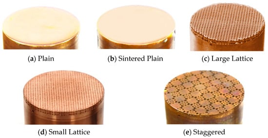
Figure 1.
Test piece configurations. (a) Plain: uniform solid copper block. (b) Sintered Plain: 20mm sintered copper powder between two solid copper blocks. (c) Large Lattice, (d) Small Lattice, and (e) Staggered: all feature a 2 mm 3D-printed layer on a copper substrate.
The Plain test piece was for experiment integrity validation. The Sintered Plain test piece was fabricated from a 6 mm-thick sintered copper powder, sandwiched between two solid copper rod sections (Figure 2a), and served as a baseline for comparison against the porous test pieces. It was intended to confirm that the sintering process does not significantly alter the heat transfer characteristics of a uniform solid copper rod, implying that 3D-printed and sintered copper parts would exhibit similar heat transfer performance to solid copper.
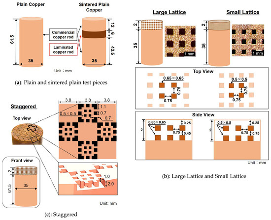
Figure 2.
Surface characteristics of the BJ3DP Surfaces. (a) Plain and Sintered Plain test pieces, (b) Large Lattice and Small Lattice, and (c) Staggered.
The three distinct 3D-printed porous copper test pieces, the Large Lattice, Small Lattice (both featuring a square lattice geometry), and the Staggered surface, which showcased a unique arrangement of square pores, are described here. Each was fabricated on a 35 mm diameter, 61.5 mm long copper rod. A 2 mm-thick porous copper section was 3D-printed and sintered onto this substrate using the binder-jetting 3D-printing (BJ3DP) process, resulting in a final height of 63.5 mm for each test piece.
The nominal geometric parameters for each porous structure, derived from their CAD designs, are detailed below and are visually represented in Figure 2b,c. These designs were specifically chosen to systematically investigate a spectrum of porous structures achievable through BJ3DP, ranging from highly interconnected, uniform networks to more patterned, localized porous arrangements. This approach provides comprehensive insights into their respective boiling heat transfer characteristics, aiding in the identification of promising design principles for future optimization, particularly in enhancing capillary wicking and facilitating efficient vapor–liquid separation during boiling.
Large Lattice surface (Figure 2b, left): This surface features a square lattice geometry designed to create a fully interconnected network of through pores.
- Pore dimensions (top and internal): The square pores have dimensions of 0.65 mm × 0.65 mm. These pores are designed to be through pores, extending vertically from the heated surface down to the bottom of the 2 mm-thick printed structure;
- Horizontal pore spacing (strut width): 0.75 mm;
- Lateral interconnectivity: The pores also extend horizontally, connecting across the diameter of the cylindrical test piece, forming a continuous network in the lateral direction;
- Porous layer height: The overall height of the 3D-printed porous section is 2 mm;
- Vertical pore arrangement: Within the 2 mm height, layers of these through pores are vertically offset. The top layer of pores begins at a vertical depth of 0.25 mm from the heated surface, and subsequent vertical layers of pores are spaced 0.45 mm apart. The horizontal spacing between the pores remains 0.75 mm throughout the depth.
Small Lattice surface (Figure 2b, right): Similar to the Large Lattice, this surface also utilizes a square lattice geometry with fully interconnected through pores but at smaller dimensions.
- Pore dimensions (top and internal): The square pores have dimensions of 0.5 mm × 0.5 mm. These pores are also designed as through-pores, extending vertically from the heated surface down to the bottom of the 2 mm-thick printed structure;
- Horizontal pore spacing (strut width): 0.75 mm;
- Lateral interconnectivity: Like the Large Lattice, the pores extend horizontally to connect across the diameter of the test piece, ensuring continuous lateral pathways;
- Porous layer height: The overall height of the 3D-printed porous section is 2 mm;
- Vertical pore arrangement: Within the 2 mm height, layers of these through pores are vertically offset. The top layer of pores begins at a vertical depth of 0.25 mm from the heated surface, and subsequent vertical layers of pores are spaced 0.75 mm apart. The horizontal spacing between pores remains 0.75 mm throughout the depth.
Staggered surface (Figure 2c): This design features a more complex, staggered pattern of distinct square pores and solid copper patches within its 2 mm-thick, porous layer. The surface is characterized by an alternating arrangement of plain (solid copper) and porous regions.
- Overall pattern spacing: The designed horizontal and vertical distance between the centers of adjacent plain and porous areas was 3.8 mm;
- Pore sizes within porous regions:
- o
- Larger square pores: 1.1 mm × 1.1 mm;
- o
- Medium square pores: 0.7 mm × 0.7 mm;
- o
- Smaller square pores (typically at the center of porous regions):
- 0.5 mm × 0.5 mm.
- Internal structure (grooves): The porous regions incorporate a grooved design within the 2 mm layer. The designed depth of these grooves (forming porous structures) was 2 mm, and the height of the individual porous structures within these grooves was 1 mm.
These designed geometries aim to create highly interconnected porous networks, crucial for enhancing capillary wicking and facilitating efficient vapor–liquid separation during boiling. However, the structures of “Lattice” and “Staggerd” are fundamentally different, and we observed the differences.
2.3. Capillary Action and Wickability
Capillary action plays a vital role in fluid transport across enhanced heat transfer surfaces, especially in pool boiling. It continuously draws liquid into the heated surface, maintaining contact with active nucleation sites and promoting the efficient formation of vapor bubbles. By penetrating microscopic pores, capillary action increases the density of active nucleation sites [41]. Furthermore, the continuous replenishment of liquid through porous channels facilitates a rapid rewetting of the surface post-bubble departure, reducing the likelihood of dry-out regions; ensures efficient vaporization; and consequently, enhances overall heat transfer [42]. Capillary forces can also temporarily counteract the buoyant force that would otherwise rapidly remove vapor bubbles from the heated surface, thereby promoting vapor retention and a more stable boiling process. However, as a bubble grows to a critical diameter, a balance is reached where capillary forces are ultimately overcome by buoyancy, leading to the vigorous detachment of the vapor bubble [43]. Figure 3 presents a detailed model of the 3D porous structures and indicates the directions of wickability. In the lattice structure, vapor and liquid can move freely in the vertical, horizontal, and height directions across the entire heat transfer surface. In contrast, in the Staggered structure, each element is isolated, except for the peripheral staggered region. It means that the lateral ingress of vapor and liquid is restricted.
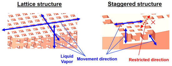
Figure 3.
Movable range of liquid and vapor in porous surface structures.
2.4. Capillary Wicking Measurement
The capillary wicking capability of the 3D-printed porous surfaces (Large Lattice, Small Lattice, and Staggered) was quantitatively evaluated by measuring their respective liquid suction speeds. The experimental procedure was adapted from the capillary-wicking test presented by Manetti et al. [24]. For these measurements, a Pyrex glass capillary tube with an inner diameter of 1 mm was utilized. All measurements were conducted at room temperature using ethanol as the working fluid. A high-speed camera (Nova S16, Photron, Tokyo, Japan) was employed to record the wicking process at a speed of 16,000 frames per second (fps). The results are presented in Figure 4.
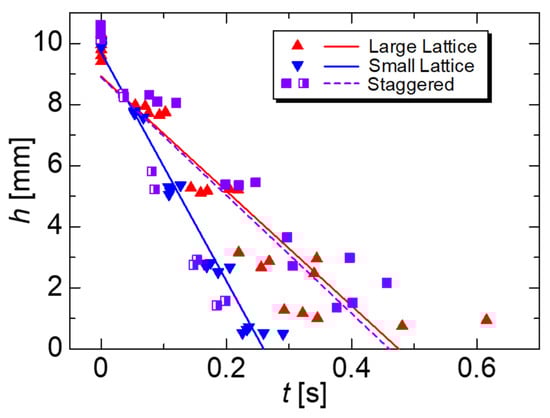
Figure 4.
Capillary absorption performance of three porous surface structures (Small Lattice, Large Lattice, and Staggered).
Each structure’s absorption rate is a direct indicator of its capillary force strength. The Small Lattice structure demonstrates the highest absorption rate at 37.381 mm/s, signifying the most robust capillary action. This rapid movement is facilitated by its smaller pore spacing and highly interconnected pathways, which are critical for quickly replenishing liquid and rewetting surfaces during boiling, ultimately improving heat transfer efficiency.
Conversely, the Large Lattice and Staggered structures exhibit significantly slower absorption rates (18.772 mm/s and 19.324 mm/s, respectively)—roughly half that of the Small Lattice. This reduced speed is attributed to weaker capillary forces, as their larger pore spacing diminishes capillary pressure and slows liquid ascent.
These findings highlight a clear relationship between capillary absorption and the geometric design of porous surfaces. Our experimental measurements of liquid suction speeds align perfectly with theoretical expectations for capillary phenomena: smaller pores inherently produce stronger capillary forces, leading to faster fluid rise. This principle is vital for effectively rewetting nucleation sites during boiling, emphasizing the fundamental link between pore geometry, fluid properties, and capillary-driven transport in 3D-printed thermal surfaces. The complex dynamics of liquid within porous media are primarily controlled by capillary forces, where capillary pressure (ΔP), which drives liquid into small pores, is defined by the Young–Laplace equation.
where ΔP is the capillary pressure, γ is the surface tension, θ is the contact angle of the liquid on the solid surface, and r is the effective pore radius. This equation clearly indicates that smaller pore radii directly result in proportionally higher capillary pressures. Our designed porous structures directly leverage this principle: the Small Lattice features nominal square pore dimensions of 0.5 mm × 0.5 mm, resulting in a smaller effective pore radius compared to the Large Lattice, which has nominal square pores of 0.65 mm × 0.65 mm. This intrinsic difference in pore geometry dictates their respective capillary strengths and fluid-wicking capabilities.
Furthermore, the dynamics of liquid penetration into porous structures due to capillary action can be approximated by the Lucas–Washburn equation, particularly for initial wicking:
where L is the penetration length, μ is the dynamic viscosity of the fluid, and t is the time. This equation provides a theoretical framework for understanding observed liquid suction speeds, demonstrating that faster liquid penetration (higher suction speed) is favored by smaller pore radii, higher surface tension, lower viscosity, and better wettability.
2.5. Surface Roughness
The surface roughness of the BJ3DP test pieces was evaluated using a Keyence VK-X3000 laser microscope (Keyence, Osaka, Japan) equipped with a white-light interferometer. This non-contact measurement system provides high spatial resolution with a precision of 0.1 nm, enabling an accurate detection of micro-scale surface variations that contact-based profilometers may not fully capture. Surface roughness measurements were conducted on a representative sample fabricated using the BJ3DP process. Figure 5 shows the measurement area. From this figure, ten distinct lines, labeled ① through ⑩, were selected for detailed evaluation. The corresponding roughness values for these lines are summarized in Table 1.
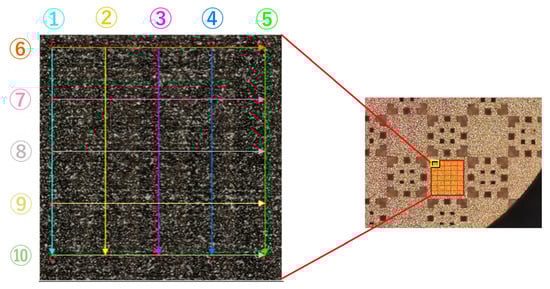
Figure 5.
Location of surface roughness measurement.

Table 1.
Surface roughness measurements.
The average arithmetic mean roughness (Sa) across the evaluated area was 9.14 μm, while the maximum height roughness (Sz) reached 108.5 μm. These results indicate a significantly rough surface characteristic of the components produced by metal additive manufacturing processes like BJ3DP.
According to Fan et al. [44], test surfaces with higher roughness values within a reported range of Sa = 0.045 to 1.22 μm demonstrated improved heat transfer performance in pool-boiling applications. While the average Sa measured in the present study (9.14 μm) exceeds this specific range cited by [44], the enhanced complex surface topography produced via additive manufacturing is expected to promote bubble nucleation and vapor–liquid interactions significantly. The literature also suggests that the relationship between roughness and heat transfer enhancement depends on the specific surface preparation method. Consequently, despite exceeding the range from this particular study, the high and complex roughness achieved through BJ3DP is anticipated to positively impact boiling heat transfer efficiency by providing a high density of active nucleation sites.
2.6. Surface Characterization via Scanning Electron Microscopy (SEM)
SEM imaging was performed to investigate the surface of the 3D-printed copper porous structure at the microscale (Figure 6). A JEOL JCM-7000 scanning electron microscope (JEOL, Tokyo, Japan) was used. The image was acquired with a secondary electron detector (SED) at an accelerating voltage of 5.0 kV, and a working distance (WD) of 61.8 mm was maintained for both 50 μm and 20 μm scale images. High vacuum conditions were used with a vacuum reading of 400 for the 50 μm and 800 for the 20 μm image. Figure 6 shows a SEM image area corresponding to a plain surface fabricated through BJ3DP. The surface is rough and irregular, with finer details such as cavities created during manufacturing due to the sintered copper particles visible at this scale. These cavities are known to promote the formation of boiling nucleation sites, and a higher density of such cavities is desirable to increase the number of active nucleation sites, thereby enhancing boiling heat transfer performance. This characteristic unevenness is consistent with a porous layer formed by sintered powder. The size and distribution of these features are influenced by the size and morphology of the initial powder particles and the sintering parameters. Hence, the resultant porous layer formed by sintered particles leads to a surface rich in cavities, which act as nucleation sites, promoting bubble formation and ultimately enhancing the efficiency of boiling heat transfer. Accordingly, such cavity structures on the test pieces used in this study are expected to enhance the heat transfer efficiency during boiling.
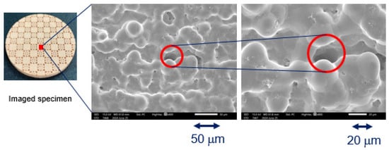
Figure 6.
SEM images of the BJ3DP surface.
2.7. Experimental Apparatus
Figure 7a,b show a photo and schematic diagram of the experimental setup used to study the pool-boiling heat transfer performance on the 3D-printed surfaces. The working fluid used in all experiments was de-ionized and de-gassed water. The main components of the experiment consist of the boiling chamber, primary and secondary heating sections, a coil condenser, a boiling visualization system, and a data acquisition system.
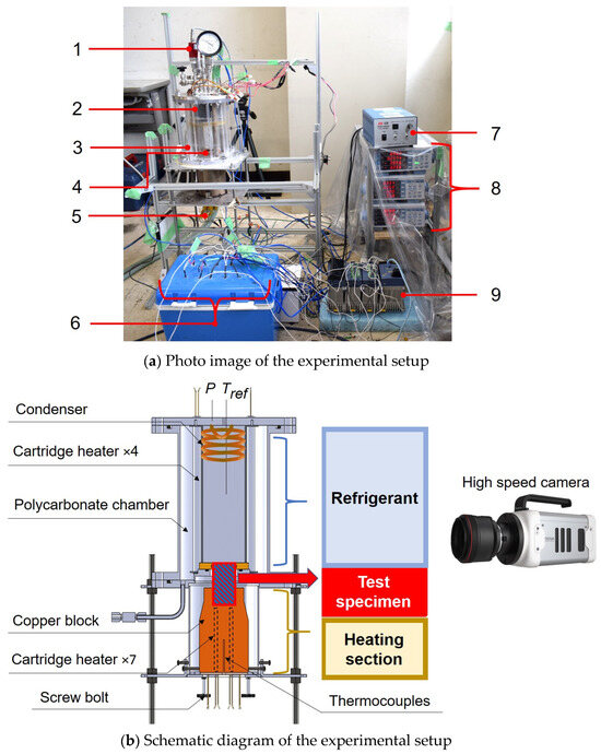
Figure 7.
(a) Photo image of the experimental setup; (b) schematic diagram of the experimental setup.
The boiling chamber is made of cylindrical reinforced polycarbonate glass with a wall thickness of 3 mm, an outer diameter of 150 mm, and a height of 237 mm. The polycarbonate glass allows the boiling process inside the chamber to be visualized. Two-thirds of the vessel was filled with the working fluid before each experiment.
The primary heating section consists of seven 600 W cartridge heaters (totaling 4200 W) installed at the bottom of a copper block. These heaters are controlled by two single-winding variac transformers (bolt sliders) powered by 200 V AC, allowing for precise regulation of the input heat flux to the test piece. However, as shown in Figure 7b, the measurement limit is reached when the temperature of the thermocouple located at the center of the cartridge heater section approaches the melting point of copper (1084.5 °C). The copper block is precisely designed with a hollow section at its top to fit the bottom part of the test piece with exact precision, ensuring negligible contact resistance and promoting uniform heat flow. To minimize heat loss from the sides and ensure that nearly all the generated heat is directed to the test section, the entire copper block is thoroughly insulated with glass wool. The design features, including copper block fitting and insulation, are crucial for minimizing radial heat losses and thereby limiting the influence of edge effects on the primary heat transfer surface.
The secondary heating section maintains the working fluid’s saturation temperature throughout the experiment. It comprises four 250 W cartridge heaters installed through protective tubes and immersed in the boiling chamber. Their output is controlled by a single small bolt slider (single winding Variac transformer) powered by 100 V AC. These heaters serve the crucial purpose of maintaining the bulk fluid at saturation and compensating for ambient heat losses from the chamber, thereby ensuring pure pool-boiling conditions with negligible sub-cooling.
Several K-type thermocouples were used in the experiment. The fluid saturation temperature () was measured by a K-type thermocouple positioned at the top of the boiling chamber and immersed in the fluid. Four K-type thermocouples were embedded within the solid copper base of the test piece at different axial locations along the heat flow path to measure the temperature gradient. A linear regression based on these temperature measurements was used to determine the wall superheat () at the boiling surface. These thermocouples were precisely calibrated to minimize errors during temperature measurements.
A pressure gauge was installed on the flange at the top of the boiling chamber. An FP101A (Yokogawa Electric, Tokyo, Japan) absolute pressure gauge measures the vessel’s pressure to maintain atmospheric pressure during experiments by controlling the condenser.
For visualization, a high-speed camera model Nova S16 (Photron), recording at 16,000 frames per second (fps) with a shutter speed of 1/200,000 s and a resolution of 1024 × 1024 pixels, was used to capture the boiling process. A lighting strobe on the camera side and a panel light (WTT 120120(8) from Nissin Electronics, Tokyo, Japan) on the opposite side were used as a backlight to ensure high image quality.
A spiral-coil copper condenser with circulating coolant condensed the vapor to maintain atmospheric pressure. This also reduced evaporation and maintained the fluid level in the boiling chamber.
The data acquisition unit, MX100 (Yokogawa Electric), was used to monitor the input power values and measure the temperature and pressure data from the boiling setup. Temperature, pressure, and power data were continuously transmitted to a PC at a frequency of 1 Hz via the data acquisition unit, allowing for the experimental apparatus to be constantly monitored.
A power supply and Variac transformers (YAMABISHI, Tokyo, Japan) were used to control heat inputs. The input power to the copper block was regulated by two Variac transformers powered by 200 V AC, while the input power used to heat the fluid was controlled by a single small Variac transformer powered by 100 V AC.
At the start of each experiment, the vapor phase above the liquid was de-gassed using a vacuum pump. Then, the fluid was brought to a boil using the auxiliary heaters and maintained in a boiling state for one hour before commencing data acquisition to ensure thermal equilibrium and remove dissolved gases.
2.8. Data Reduction and Uncertainty Analysis
Figure 8a illustrates the test section setup and a representative temperature profile within the solid copper base. Figure 8b shows a schematic indicating the placement of sheathed K-type thermocouples (labeled and ) embedded along the central axis at different depths within the copper block to measure the temperature gradient during the pool-boiling experiments.
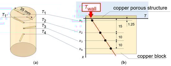
Figure 8.
Test section view: (a) locations where the thermocouples were inserted, (b) representative plot of the temperature profile along the block height.
Heat flux calculation: The heat flux (q) passing through the copper block and into the test surface was calculated using Fourier’s Law of heat conduction, based on the measured temperature gradient within the solid copper base, as in Equation (1).
where is the thermal conductivity of copper, and is the temperature gradient in the direction of heat flow (axial).
Temperature gradient determination: The temperature gradient along the primary heat conduction path was established by measuring temperatures at four distinct K-type thermocouple locations (, , , and ) at corresponding depths (x1, x2, x3, and x4) (Figure 8b).
A linear regression approach was used to derive the temperature gradient. The linear relationship is expressed as:
where T is the temperature (K), m is the temperature gradient (), x is the axial position (m), and b is the intercept. This method assumes one-dimensional, steady-state conduction, which is reasonable due to the central placement of thermocouples, minimizing the lateral conduction effects.
It is worth noting that, even though we have five measurement locations, we only use four thermocouples for our calculations. The fifth point, x1’, is positioned off-center. Its sole purpose is to verify that the temperature is uniform across the entire heat transfer surface.
Uncertainty analysis of heat flux: An uncertainty analysis was conducted to evaluate the reliability of the calculated heat flux (q) values. The primary source of uncertainty in the heat flux calculations is directly attributed to the uncertainty in the temperature gradient , as is a material property. The residuals, were then used to compute the residual sum of squares (RSS), from which the variance of the fit was obtained. The uncertainty in the slope, representing the standard error was then calculated using the formula:
The uncertainty in the calculated heat flux primarily arises from the uncertainty in the slope of the temperature profile, which stems from uncertainties in the measured temperatures, the precision of thermocouple placement, and the defined distances. The associated standard uncertainty in the heat flux, , is computed as the product of the copper thermal conductivity and the standard uncertainty of the slope.
Wall superheat determination: The temperature at the heating surface () was determined by extrapolating the linear temperature profile measured by the embedded thermocouples to the position of the boiling surface () to the position of the boiling surface (x = 0). The wall superheat () was then calculated as the difference between the extrapolated wall temperature and the measured saturation temperature of the fluid, as shown in Equation (4):
The saturation temperature corresponds to the temperature at which the saturation pressure is measured using a pressure gauge.
Heat transfer coefficient: The heat transfer coefficient (h) was calculated using Newton’s Law of Cooling, as shown in Equation (3).
where is the calculated heat flux, and is the determined wall superheat.
Combined standard uncertainty in the heat transfer coefficient: The uncertainty evaluation for the heat transfer coefficient was based on the error transmission method. Uncertainties in both the wall temperature and saturation temperature contribute to the overall uncertainty in the heat transfer coefficient. Using uncertainty propagation, the combined standard uncertainty of the heat transfer coefficient,, was calculated by accounting for the individual contributions from heat flux, wall temperature, and saturation temperature as the square root of the sum of the squares of these individual uncertainties. The formula used is:
The calculated uncertainty values for and are presented in Table 2. Notably, the uncertainty values tend to be larger for the test specimens with a higher wall superheat.
Table 2.
Calculated uncertainty analysis of the heat flux and heat transfer coefficient.
It is important to note that corresponds to , which is the standard error of the intercept from the linear regression used to determine the temperature gradient corresponds to the error of the pressure gauge, particularly since the saturation temperature in this work was determined based on the saturation pressure measured by a pressure gauge.
2.9. Reliability of Experimental Setup
To verify the reliability and overall integrity of the experimental apparatus, tests were carried out on the Plain (polished) and Sintered Plain test pieces using de-ionized and de-gassed water. The experimental results were compared with the widely applicable and extensively used Stephan–Abdelsalam correlation [45] for nucleate pool boiling in water. Proposed in 1980, this empirical correlation requires no tuning parameters for nucleate pool boiling in water. Proposed in 1980, this empirical correlation requires no tuning parameters [46,47,48], contributing to its value and frequent citation [49,50,51]. Its adaptability and proven success in applied research underscore its significance in boiling heat transfer. The Stephan–Abdelsalam correlation for water on a plain surface is given by Equation (4) [45].
where
| Nusselt number (dimensionless heat transfer coefficient) | ||
| Heat flux | ||
| Bubble departure diameter | ||
| Thermal conductivity of liquid | ||
| Saturation temperature | ||
| Latent heat | ||
| Thermal diffusivity of liquid | ||
| Specific heat of liquid at constant pressure | ||
| Density of liquid | ||
| Density of vapor |
The correlation implicitly accounts for the type of fluid through its properties ) obtained from REFPROP steam tables. The experimental data provided The bubble departure diameter (d) is crucial for the Stephan–Abdelsalam correlation and was calculated using Equation (5), as provided in the model [45].
Experiments with the Plain and Sintered Plain test pieces were conducted under the same conditions to confirm repeatability. Figure 9 shows the results of the two similar experiments, which match well with the predictions from the Stephan and Abdelsalam correlation, confirming the reliability and integrity of the experimental apparatus. Thus, the experimental setup was well fabricated, and the results are considered trustworthy and repeatable. Therefore, the thermal resistance between the solid copper rod (Plain) and the additively manufactured copper rod (Sintered Plain) is considered negligible, and the results are analyzed accordingly.
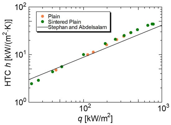
Figure 9.
Pool-boiling validation against Stephan & Abdelsalam correlation.
Important considerations for validation included the surface condition, since the Stephan–Abdelsalam correlation does not explicitly account for surface roughness. The surface of the Plain samples was polished to a mirror finish using abrasive paper of different sizes, followed by a rubbing compound, achieving a clean mirror shine surface. The second consideration was maintaining atmospheric pressure using the pressure gauge and condenser to ensure that the working fluid properties corresponded to the correct saturation temperature.
3. Results and Discussion
3.1. Heat Flux–Wall Superheat Relationship
3.1.1. Boiling Curve Analysis
Figure 10 illustrates the pool boiling performance (Heat Flux vs. Wall Superheat) of the Sintered Plain, Large Lattice, Small Lattice, and Staggered surfaces in de-ionized and de-gassed water at atmospheric pressure, as represented by the boiling curves.
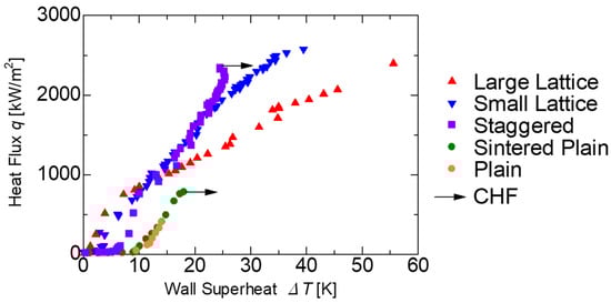
Figure 10.
Boiling curves for various 3D-printed geometric structures in comparison to plain surface.
The Plain and Sintered Plain surfaces exhibit similar trends in wall superheat with respect to heat flux, indicating that the metal sintering process does not introduce additional thermal adverse effects. The Staggered surface and the Plain surface both showed an increase in wall superheat with increasing heat flux, with the trend for the Staggered surface being more suppressed, resulting in a steeper slope in the boiling curve. Sintered Plain and Staggered surfaces reached their critical heat flux (CHF) at 782 kW/m2 and 2342 kW/m2 respectively.
In contrast, the Large Lattice and Small Lattice exhibit continuously rising heat flux with increasing wall superheat up to the experimental limit, without exhibiting a traditional CHF phenomenon. The highest heat flux recorded for the Large Lattice and Small Lattice surfaces was 2398 kW/m2 and 2577 kW/m2, respectively. The wall superheat continued to rise while maintaining a stable temperature gradient.
However, as noted in Section 2.7, based on Figure 7b, the experiment was terminated once the temperature near the cartridge heaters approached the melting point of copper, indicating a system-level thermal limit rather than a boiling crisis on the surface. Throughout this period of extremely high heat fluxes, there was no visible evidence of a stable blanket vapor film forming on the heating surface, nor any indication of thermal instability or overshoot in wall superheat. This suggests that a dynamic and robust balance between liquid supply to the heating surface and vapor bubble departure was maintained.
As illustrated in Figure 3, lattice structures allow for liquid supply and vapor departure in all three spatial directions. Furthermore, under high heat flux conditions where vapor growth rates are significant, the 3D dispersion provided by the lattice structure was highly effective in preventing vapor bubble coalescence on the heating surface. This extraordinary and sustained high-performance behavior results directly from the lattice structure’s exceptional design and geometry. The surface maintains active rewetting and efficient heat transfer despite increasing wall superheat, fundamentally delaying the boiling crisis mechanism.
Notably, the Small Lattice showed the steepest slope on the graph, meaning that the rise in wall superheat with increasing heat flux was the most suppressed. Additionally, for the Small Lattice near 750 kW/m2, and the Large Lattice near 1000 kW/m2, an increased rate of wall superheat rise was observed, suggesting that the vapor bubble departure diameter may be changing in response to the square pore size of each structure.
While all the BJ3DP structured surfaces significantly improve boiling heat transfer, the Large Lattice and Small Lattice designs demonstrate a higher degree of robustness against the boiling crisis, effectively extending the nucleate boiling regime beyond the traditional CHF point observed for the Staggered surface.
3.1.2. Comparative Analysis of Boiling Curve with the Literature Data
Figure 11 presents a comparative analysis of the current study with selected literature data to provide context for the observed heat transfer performance. While the figure indicates that some studies report higher CHF values than those achieved in the current work, a fundamental distinction lies in the unique boiling behavior observed for our lattice structures. Specifically, the Large Lattice and Small Lattice did not reach CHF within the limits of this experiment. Instead, these lattice surface structures demonstrated a stable boiling behavior in which the wall superheat gradually increased while maintaining robust heat transfer capability, even at the highest heat fluxes achieved.
When the heat flux range is segmented for comparison, it is evident that at lower heat flux (at or below 750 kW/m2), all porous surface structures, including the Staggered, exhibit similarly high heat transfer performance, comparable to much of the literature data.
Stable operation at high heat flux without reaching or delaying the boiling hysteresis is desirable in practical applications. Therefore, the lattice structures demonstrated robustness and stability, as evidenced by their ability to sustain high heat fluxes without reaching thermal instability. Furthermore, an enhancement of up to 230% in CHF (relative to the plain surface) is comparatively strong and competitive within the field of boiling heat transfer enhancement.
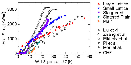
Figure 11.
Comparative analysis of the relationship between heat flux (q)—wall superheat (): This study vs. Liu et al. [29], Zhang et al. [52], Elkholy et al. [53], Pi et al. [54], and Mori et al. [55].
3.2. Heat Transfer Coefficient Analysis
Figure 12 presents the HTC and heat flux for the various surface structures studied in comparison to literature data. All surfaces showed a general increasing trend in HTC, particularly in the low heat flux region (≤750 kW/m2). Consistent with the boiling curves (Figure 10), the HTC of the Large Lattice, Small Lattice, and Staggered surfaces was significantly higher than that of the Plain and Sintered Plain throughout the range of heat fluxes.
The Sintered Plain surface exhibited an increasing HTC trend up to its maximum HTC of 43.34 kW/(m2·K) corresponding to its CHF of 782 kW/m2 at a wall superheat of 18.03 K. The Staggered surface showed a rapid increase in HTC at low heat fluxes, followed by a more gradual increase. Its peak HTC of 95.34 kW/(m2·K) was achieved at a CHF of 2342.4 kW/m2, with a wall superheat of 24.57 K.
The Large Lattice and Small Lattice surfaces showed a rapid growth in HTC within the low to medium heat flux region, reaching their highest HTC values early in this range. The Small Lattice reached a peak HTC of 95.62 kW/(m2·K) at a heat flux of 272.72 kW/m2 and a corresponding wall superheat of 2.85 K. The initial rise and peak were followed by a steady decrease in HTC, with its final HTC at the maximum heat flux recorded being 65.3 kW/m2 K at the maximum heat flux achieved of 2577. kW/m at a wall superheat of 39.5 K. Similarly, the Large Lattice reached its highest HTC of 133.41 kW/(m2·K) at a heat flux of 513.97 kW/m2 and a corresponding wall superheat of 3.85 K. However, the HTC decreased steadily to 43.14 kW/(m2·K) at its maximum achieved heat flux of 2397.7 kW/m2 at a wall superheat of 55.6 K.
A notable trend for the Large Lattice and Small Lattice surfaces is an initial rise in HTC at lower heat fluxes, followed by a subsequent gradual decrease as the heat flux continues to increase. This behavior can be attributed to the evolving dominance of different heat transfer mechanisms at both low and high heat flux within the nucleate boiling regime. At lower heat fluxes, the Large and Small Lattice surfaces show a rapid increase in HTC, driven by enhanced nucleation site activation, efficient liquid replenishment facilitated by bubble dynamics, and the unique 3D architecture that ensures adequate liquid supply and vapor departure. High nucleation site density, along with grooves and cavities, promotes evaporation and vapor–liquid interaction, maximizing bubble-induced convection and overall heat transfer. As the heat flux increases, the HTC begins to decline despite the rising heat flux. This is attributed to a shift in the dominant boiling mechanism, transitioning from discrete bubble departure to a more complex regime of vapor flow and liquid rewetting. This is coupled with increased bubble interactions and coalescence, as well as vapor jet formation, which reduces the effective heat transfer area. While this activates more sites, dense bubble populations impede liquid motion, reducing convective efficiency and leading to greater vapor coverage on the surface, resulting in a gradual increase in thermal resistance. However, as discussed in Section 3.1 and further elaborated below, this did not trigger a boiling crisis or traditional CHF due to the optimized pore size and permeability of the lattice structures. These features enable efficient liquid replenishment and vapor escape, mitigating accelerated bubble crowding and allowing them to achieve peak HTC early with less severe declines. The structures effectively separate liquid and vapor pathways, delaying film boiling and dryout by facilitating rapid bubble departure and continuous liquid supply through connected pores, reflecting a trade-off between initial bubble-enhanced mixing and reduced liquid contact at higher densities. The HTC improvement achieved in this study in comparison to the plain surface was up to 118.7% for the Staggered surface, 119.3% for the Small Lattice, and 206% for the Large Lattice, compared to the Sintered Plain surface.
Comparative Analysis of HTC with Literature
In comparing the HTC vs. heat flux graph (Figure 12) with other literature data, at the lower heat flux range (generally below ~750 kW/m2), all the porous surface structures, including Large Lattice, Small Lattice, and Staggered, demonstrate comparable or superior HTC values compared to much of the included literature data in this range. Starting generally at similar HTC values to the literature data at low heat fluxes, they then rise more steeply and stand out significantly, indicating better heat transfer performance. At the medium heat flux range (~1000 kW/m2), the Large Lattice, Small Lattice, and Staggered surfaces are comparable to literature values. While some literature data (Liu et al. [29] and Zhang et al. [52]) indicate higher HTC values, the Large Lattice and Small Lattice decrease gradually with an increase in heat flux, while maintaining relatively high HTC values. The Large Lattice slope decreases more while the Small Lattice flattens out. The Staggered surface also exhibits strong performance, maintaining a relatively high HTC and achieving a higher heat flux than the data points of Elkholy et al. [53], Pi et al. [54], and Mori et al. [55]. Its HTC shows a stable, slightly increasing trend at its highest heat fluxes compared to the initial rise.
Generally, the Large Lattice and Small Lattice surfaces demonstrate a superior ability to maintain high HTC at extremely high heat fluxes where many conventional surfaces or even some enhanced surfaces might have already experienced a boiling crisis. The Staggered surface also shows competitive performance, particularly in extending the range of high HTC compared to the Sintered Plain surface. This highlights the effectiveness of 3D-printed porous structured surfaces in enhancing boiling heat transfer performance.
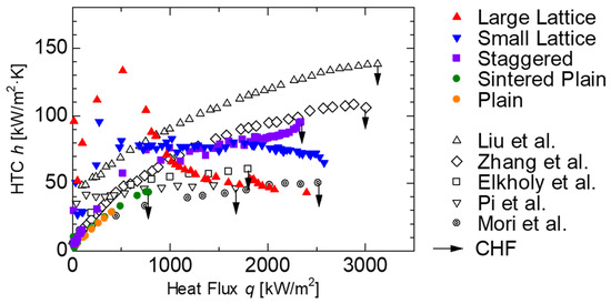
Figure 12.
Comparative analysis of the relationship heat transfer coefficient (h) and heat flux (q): This study vs. Liu et al. [29], Zhang et al. [52], Elkholy et al. [53], Pi et al. [54], and Mori et al. [55].
3.3. Mechanisms of Enhanced Boiling Heat Transfer
The superior boiling heat transfer performance of the Large Lattice and the Small Lattice stems from their ability to primarily alter the bubble dynamics and liquid supply, and this is achieved through:
- Enhanced nucleation site density: At lower heat fluxes, the porous structures, i.e., Large Lattice, Small Lattice, and Staggered, provide a significantly higher density of active nucleation sites compared to the Sintered Plain. This promotes earlier vapor (bubble) incipience, leading to more frequent and improved vapor (bubble) departure with less resistance. This mechanism is critical for efficient heat dissipation in the low heat flux region;
- Capillary wicking and lattice structure: As shown in Figure 3, thess unique and highly interconnected 3D pore networks within the Large Lattice and Small Lattice structures with specific design dimensions, i.e., 0.65 mm × 0.65 mm for the Large Lattice and 0.5 mm × 0.5 mm for the Small Lattice, enables exceptionally efficient and continuous liquid supply to the heat transfer surface through robust capillary wicking. This capillary action maintains wetting and efficient vapor generation and departure rates. The observed difference in HTC trends between the Small Lattice and the Large Lattice with changing heat flux is attributable to the pore size of the lattice. The smaller pore size provides stronger capillary forces and a more interconnected cavity structure, potentially resulting in more controlled vapor escape and improved localized rewetting;
- Effective liquid–vapor pathways: Simultaneously, these structures provide highly effective and direct pathways for vapor escape, preventing vapor accumulation and the formation of an insulating film that typically triggers CHF. The continuous rewetting and efficient vapor removal basically alter the boiling crisis pathway, allowing these surfaces to sustain heat transfer rates without entering film boiling, even at elevated wall superheats, representing a significant advancement in enhancing boiling stability for high heat flux thermal management.
The distinction in CHF behaviors between the Staggered surface, which showed a clear CHF characteristic, and the Large Lattice and Small Lattice lies in the details of their internal geometry and pore interconnectivity. While the Staggered design is highly effective in increasing the CHF due to its specific arrangement of alternating plain and porous surfaces, it lacks full interconnectivity, leading to localized vapor blockage or liquid supply limitation at its CHF, which eventually overwhelms its rewetting capacity, resulting in a distinct CHF transition. The uniform and optimized interconnectivity of the Large Lattice and the Small Lattice structures provides an even higher degree of robustness against these instabilities, allowing for stable operation beyond the traditional CHF point.
3.4. Heat Flux Regimes and Dominant Mechanisms
To understand the boiling phenomenon, particularly where heat transfer surfaces recorded higher heat fluxes without reaching the traditional CHF, we discuss the boiling heat transfer performance of the tested surfaces by dividing the data into three distinct heat flux regions: the low heat flux region (≤750 kW/m2), the medium heat flux region (>750 kW/m2 and ≤2000 kW/m2), and the super-high heat flux region (>2000 kW/m2). These regions represent different boiling regimes characterized by evolving bubble dynamics and dominant heat transfer mechanisms. Two key factors influencing performance across these regions are surface wettability (affected by surface roughness and capillary forces) and bubble formation and departure dynamics. Essentially, the heat flux regions correspond to increasing vapor generation rates.
- Low heat flux region (q ≤ 750 kW/m2)
In this region, discrete bubble formation and departure play a critical role. On both plain and porous surfaces, bubble formation occurs at isolated nucleation sites where individual bubbles grow before departing. For enhanced surfaces, the key factor is not intrinsic surface wettability but rather the promotion of frequent bubble departure and effective rewetting. The structured porous surfaces of the Large Lattice, Small Lattice, and Staggered promoted earlier bubble incipience and enhanced nucleation, leading to more frequent and improved bubble departure with minimum resistance and allowing for better surface rewetting. Here, the primary heat transfer mechanisms are evaporation at the bases of isolated bubbles and natural convection. The porous structures enhance heat transfer by increasing the density of active nucleation sites and maintaining good surface wettability through improved liquid access to the bubble base.
At the onset of nucleate boiling, the Sintered Plain surface exhibited higher wall superheat than the Large Lattice, Small Lattice, and Staggered. For instance, the onset of nucleate boiling on the Large Lattice and Small Lattice occurred at very low wall superheats, indicating highly effective nucleation sites provided by the porous structures. This contrasts with the Sintered Plain surface, which required a higher wall superheat to initiate and sustain bubble growth. The porous structures served as vapor traps and acted as effective nucleation sites for the Large Lattice, Small Lattice, and Staggered.
The Large Lattice and Small Lattice surfaces exhibited superior boiling heat transfer compared to the Sintered Plain and generally performed slightly better than the Staggered surface in the very low heat flux range. As the heat flux increased within this region, the Staggered surface achieved higher heat fluxes at lower wall superheat values than the other surfaces;
- Medium-to-high heat flux region (750 < q ≤ 2000 kW/m2)
From approximately 750 kW/m2 to 2000 kW/m2, the boiling behavior transitions from isolated bubbles to more complex vapor structures, including vapor columns and mushroom-like formations, accompanied by increased bubble frequency and coalescence. Bubble growth accelerates significantly, making surface wettability and effective liquid replenishment critical to prevent dry spots.
The interconnected porous structures of the Large Lattice, Small Lattice, and Staggered surfaces were particularly effective in promoting capillary-driven liquid replenishment to the heat transfer surface. This capillary action facilitated liquid flow through separate vapor–liquid pathways within the structure to maintain wetted areas. While the Large Lattice and Small Lattice structures benefit from their 3D spatial connectivity, the Staggered surface demonstrates the best performance from around 1000 kW/m2. This suggests that the specific geometry of the Staggered structure is highly effective in this range at facilitating liquid replenishment and delaying the onset of dry spots, thereby enhancing heat transfer. This region’s main heat transfer mechanisms are driven by increased nucleation, regulated bubble evolution, and capillary action, maintaining surface wettability and preventing drying;
- Super-high heat flux region (2000 kW/m2 < q)
At these extremely high heat fluxes, vapor dynamics become increasingly complex, involving significant local heat flux variations, potential hot spots, and a high risk of reaching the critical heat flux (CHF) and transitioning to film boiling on conventional surfaces. The surface structure is critical in preventing this transition and sustaining ultrahigh heat fluxes by effectively managing vapor removal and liquid supply.
The Staggered surface eventually reached CHF within this high heat flux region and transitioned to film boiling. The delayed CHF for this test piece, compared to the Sintered Plain, was due to the enhanced mechanisms discussed in the medium-to-high flux region (improved liquid replenishment due to capillary forces).
However, a unique phenomenon was observed with the Large Lattice and Small Lattice structures: traditional CHF was not reached within the tested limits. Instead, the temperature gradient remained constant, and only the wall superheat began to increase gradually. This phenomenon, which indicates a suppression of the catastrophic transition to film boiling, has not been widely reported in previous studies. The authors attribute this to the lattice’s unique 3D internal connectivity. It is believed that this structure effectively disrupts the formation of a stable vapor film near the heated surface by breaking up the rapidly growing vapor structures three-dimensionally. While the lattice structure successfully sustains high heat flux by avoiding film boiling, the sheer rate of vapor generation likely exceeds the capacity of complete vapor removal and local liquid replenishment through internal transport alone, leading to the observed continuous increase in wall superheat despite the sustained heat flux. In this region, the surface characteristics are paramount, with the porous structures preventing film boiling through complex bubble management and liquid transport, primarily driven by capillary action and local heat flux management.
3.5. Visualisation of Bubble Characteristics
As detailed in Section 2.4 Experimental Setup, the boiling process and associated bubble characteristics were captured using a high-speed camera. Videos were recorded at 16,000 frames per second (fps) with a shutter speed of 1/200,000 s and a 1024 × 1024 pixels resolution. Figure 12, Figure 13, Figure 14, Figure 15, Figure 16, Figure 17, Figure 18 and Figure 19 show representative images of the boiling process on the heat transfer surfaces of the four test pieces at different heat fluxes.
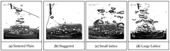
Figure 13.
Bubble growth characteristics (q = 50 kW/m2).
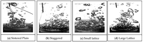
Figure 14.
Bubble growth characteristics (q = 100 kW/m2).
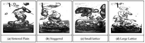
Figure 15.
Bubble growth characteristics (q = 250 kW/m2).
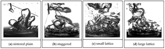
Figure 16.
Bubble growth characteristics (q = 500 kW/m2).
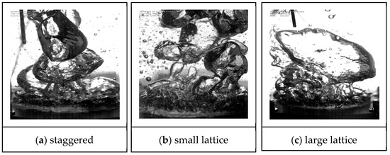
Figure 17.
Bubble growth characteristics (q = 1000 kW/m2).
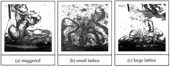
Figure 18.
Bubble growth characteristics (q = 2000 kW/m2).
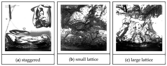
Figure 19.
Bubble growth characteristics (CHF at q = 2342kW/m2, for Staggered, q = 2397kW/m2 for Large Lattice, and q = 2577kW/m2 for Small Lattice).
At a low heat flux of 50 kW/m2 (Figure 13a–d), isolated bubbles distributed uniformly across the heat transfer surfaces were observed on all test pieces. The Large Lattice and Small Lattice surfaces exhibited a noticeably higher bubble density than the Sintered Plain. This increased density on the lattice structures can be attributed to bubbles nucleating preferentially within the interconnected porous cavities. In contrast, the Sintered Plain surface showed fewer active nucleation sites, which is consistent with requiring a much higher wall superheat to achieve significant bubble growth, as indicated by the boiling curves (Figure 10).
At a heat flux of 100 kW/m2 (Figure 14a–d), a larger number of nucleation sites were observed on the Large Lattice, Small Lattice, and Staggered surfaces. Bubble formation and departure were stable and frequent, indicating efficient heat dissipation. This vigorous bubble activity directly correlates with the rapid increase in HTC observed for these structured surfaces in this low heat flux region (Figure 12). While the high HTC at this low flux is primarily driven by the increased density of active nucleation sites provided by the structures, capillary-driven liquid supply is a major contributing factor.
Figure 15a–d shows the bubble characteristics at 250 kW/m2. For the Large Lattice, Small Lattice, and Staggered, bubbles were observed to detach from the heat transfer surface and then coalesce into larger vapor structures above the heat transfer surface. The interconnected porous cavities of the heated surface facilitate adequate liquid replenishment through capillary forces, supporting this detachment–coalescence behavior away from the surface. However, bubbles tended to merge at the heat transfer surface on the Sintered Plain before detaching, forming larger vapor slugs. These vapor slugs effectively isolate portions of the heated surface from the bulk liquid, hindering the rewetting of the heating surface.
At a heat flux of 500 kW/m2 (Figure 16a–d), the Large Lattice and Small Lattice surfaces continued to show bubbles detaching from the surface before coalescing into vapor structures above it. The formation of more defined vapor columns was observed for the Staggered surface. Bubble formation on the Sintered Plain coalesced into large, stable vapor slugs that covered a significant portion of the heat transfer surface, isolating the bulk liquid from the heating surface. This extensive vapor blanketing on the Sintered Plain led to a significant increase in wall superheat, ultimately resulting in CHF for the Sintered Plain reaching around 782 kW/m2, which is consistent with the boiling curve (Figure 10).
Figure 17a–c displays bubble characteristics at a higher heat flux of 1000 kW/m2 on the Large Lattice, Small Lattice, and Staggered surfaces. Bubbles on all three surfaces detached from the surface and coalesced into several slightly larger bubbles. Crucially, these coalesced bubbles did not form a continuous vapor film that covered the heat transfer surface. This indicated that the surface remained in contact with the bulk liquid, and liquid replenishment was sufficient, helping to maintain a lower wall superheat consistent with the boiling curve (Figure 10).
Moving to 2000 kW/m2 (Figure 18a–c), bubbles detaching from the Staggered surface coalesced on top of the heating surface, forming distinct vapor columns. While not entirely film boiling, these columns almost covered the surface, significantly hindering direct liquid contact and replenishment to the heated area due to the lack of separate vapor–liquid pathways provided by the interconnected channels on the heat transfer surface. In contrast, bubbles on the Large Lattice and Small Lattice surfaces were still observed coalescing after departure, forming several unstable vapor columns. This indicates that, on the heating surface, the vapor is segmented by the lattice structure, effectively suppressing the transition to film boiling.
Figure 19a–c shows the boiling behavior leading to CHF and the state of the surfaces at very high heat fluxes. Figure 19a shows the Staggered surface at its CHF, with the entire heat transfer surface completely covered by a stable vapor film, leading to the sudden surge in wall superheat characteristic of CHF. Figure 19a,b show the Large Lattice and Small Lattice surfaces, respectively, just before the experiment was stopped due to overheating of the copper block. Bubbles coalesced into large mushroom-like clouds on these lattice surfaces that nearly covered the entire heat transfer surface. However, the visuals showed rapid bubble nucleation, growth, and expulsion cycles. This dynamic behavior, combined with adequate liquid replenishment via capillary action, kept the heat transfer surface intermittently wetted, preventing the formation of a stable vapor film and, thus, suppressing the typical CHF phenomenon. Figure 19b,c, visually confirm the absence of a vapor blanket and the sustained, vigorous nucleate boiling, even as the heat flux, supporting the concept of an extended stable boiling regime.
3.6. Considerations on Porous Structure Characterization and Durability
The mechanistic explanations for the observed boiling enhancement, particularly the exceptional performance of the Large Lattice and Small Lattice surfaces, are primarily based on the precisely defined nominal geometries derived from their CAD designs (Section 2.2). The internal geometry of the 3D-printed structures was confirmed through detailed CAD models and high-resolution SEM images of the top surfaces (Figure 6). While metallographic microsections would provide further internal validation, the consistency of the BJ3DP process and the repeatability of the boiling results provided sufficient confidence in the as-designed pore network.
Regarding the mechanical durability of the produced porous structures, no independent mechanical tests were conducted. However, throughout the extensive pool-boiling experiments, which involved prolonged heating at high heat fluxes over several hours, the porous layers on all test pieces remained visually intact. There were no visible signs of degradation, delamination from the copper substrate, or mechanical failure observed on the surfaces. This indicates that the high-temperature sintering process created strong bonds between the copper particles and the substrate, resulting in robust and durable structures capable of withstanding the thermal and hydrodynamic stresses encountered during boiling. This inherent durability is a significant advantage for practical applications of these surfaces.
4. Conclusions
This study investigated the effect of three distinct porous structures with varying pore sizes and geometries fabricated using binder-jetting 3D printing on pool-boiling heat transfer performance. Experiments were conducted using de-ionized and de-gassed water at atmospheric pressure. The main conclusions from this study are as follows:
- Superior performance of 3D-printed structures: The 3D-printed heat transfer surfaces consistently exhibited significantly better boiling heat transfer performance than the Sintered Plain surface, being particularly notable in the low heat flux region;
- CHF and peak heat fluxes:
- The Sintered Plain surface reached its CHF at 782 kW/m2 at a wall superheat of 18.03 K.
- The Staggered surface showed a substantial CHF enhancement, reaching 2342.4 kW/m2 at a wall superheat of 24.6 K (approximately 199.7% higher than the Sintered Plain CHF).
- Notably, Large Lattice and Small Lattice structures did not reach CHF within the tested range. Instead, these surfaces sustained high heat fluxes, reaching peak values of 2397.7 kW/m2 (at a 55.6 K wall superheat) and 2577.2 kW/m2 (at a 39.5 K wall superheat). These peak heat fluxes represent increases of approximately 206.8% and 229.7%, respectively, over the Sintered Plain CHF.
- HTC Performance:
- The Sintered Plain surface showed an increasing HTC trend up to a maximum of 43.34 kW/(m2·K) corresponding to its CHF.
- The Staggered surface exhibited a rapid increase in HTC at low heat fluxes, reaching a peak of 95.34 kW/(m2·K) at its CHF of 2342.4 kW/m2.
- The Large Lattice and Small Lattice surfaces showed rapid HTC growth in the low to medium heat flux region, reaching their highest values early. Small Lattice peaked at 95.62 kW/(m2·K) at a heat flux of 272.72 kW/m2 (2.85 K wall superheat), while the Large Lattice peaked at 133.41 kW/(m2·K) at 513.97 kW/m2 (3.85 K wall superheat). Beyond these peaks, the HTC for the lattice structures decreased or flattened towards their maximum sustained values (the Small Lattice HTC was 65.3 kW/(m2·K) at a heat flux of 2577 kW/m2; the Large Lattice HTC was 43.14 kW/(m2·K) at a heat flux of 2397 kW/m2).
- At low heat fluxes, the structured surfaces significantly enhanced the HTC over the Sintered Plain. The Staggered surface showed an enhancement of up to 118.7% (approximately 2.04 times), the Small Lattice up to 119.3% (approximately 2.21 times), and the Large Lattice up to 206% (approximately 3.08 times).
- Mechanisms for enhanced performance: The superior performance of the 3D-printed structures is attributed to their porous nature, which provides enhanced nucleation site density and facilitates effective bubble management. Interconnected porous cavities create separate pathways for liquid and vapor flow, with capillary forces being crucial in replenishing liquid to the heated surface. This capillary action, combined with potential wettability gradients (particularly in the lattice design), delays dry-out and sustains high heat fluxes.
- Implications: This research clearly demonstrates the substantial improvement in pool-boiling heat transfer achieved using porous copper surfaces fabricated via BJ3DP technology. While the Staggered surface exhibited an impressive 199.7% enhancement in critical heat flux (CHF) compared to the plain surface, the Large Lattice and Small Lattice configurations showed an even more remarkable performance achieving 206.8% and 229.7% CHF enhancements at their highest recorded heat fluxes. These surfaces maintained stable boiling even under very high wall superheats, exhibiting extraordinary resistance to boiling crises. This significant finding highlights the potential of precisely engineered BJ3DP porous structures to fundamentally alter boiling behavior, paving the way for next-generation thermal management solutions capable of stable operation under extreme heat flux conditions.
Future Work: Based on these findings, the following areas are suggested for future investigation:
- Experimental studies on the pool-boiling heat transfer performance of 3D-printed structures with a wider range of geometries and pore sizes (e.g., varying pore shapes, interconnectivity levels, and porous layer thicknesses) to further optimize boiling performance;
- Experimental investigation of these structures’ pool-boiling heat transfer performance using different working fluids (e.g., refrigerants R1233zd(E)) to explore their applicability in various thermal management systems;
- Providing direct internal structural validation through non-destructive techniques such as X-ray micro-computed tomography (µCT) on as-fabricated samples, followed by destructive metallographic analyses (e.g., cross-sectional SEM, optical microscopy) on representative porous structures to verify internal pore geometries;
- Dedicated mechanical characterization tests, such as adhesion strength and fatigue resistance, will be conducted to comprehensively assess the long-term mechanical durability and reliability of these BJ3DP-fabricated porous copper structures for high heat flux applications under operational stresses.
Author Contributions
L.A.O.: Experiments, Data curation, Investigation, Formal analysis, Writing—original draft. N.F.: Preparation and Characterization of Samples, Experiments, Methodology, Visualization, and Validation. K.K.: Pool-boiling Experiments, Data curation, Writing—review and editing. T.M.: Validation, Writing—review and editing. K.E.: Conceptualized the initial idea for this research, Supervision, Resources, Writing—review and editing. All authors have read and agreed to the published version of the manuscript.
Funding
Joint research funding with Mitsubishi Materials Corporation, Incubation Center.
Institutional Review Board Statement
Not applicable.
Informed Consent Statement
Not applicable.
Data Availability Statement
The original contributions presented in this study are included in the article. Further inquiries can be directed to the corresponding author.
Acknowledgments
The authors would like to express their gratitude and are grateful for the help and cooperation from researchers Toshihiko Saiwai, Jun Kato, and Kenji Orito of Mitsubishi Materials Corporation, Innovation Center, for this study.
Conflicts of Interest
The authors declare no conflicts of interest. The funder was not involved in the study design, collection, analysis, interpretation of data, the writing of this article or the decision to submit it for publication.
References
- Kano, T.; Ono, R.; Furuya, M. Enhancement of critical heat flux with additive-manufactured heat-transfer surface. Nucl. Eng. Technol. 2024, 56, 2474–2479. [Google Scholar] [CrossRef]
- Nadjahi, C.; Louahlia, H.; Lemasson, S. A review of thermal management and innovative cooling strategies for data center. Sustain. Comput. Inform. Syst. 2018, 19, 14–28. [Google Scholar] [CrossRef]
- Dang, C.; Jia, L.; Lu, Q. Investigation on thermal design of a rack with the pulsating heat pipe for cooling CPUs. Appl. Therm. Eng. 2017, 110, 390–398. [Google Scholar] [CrossRef]
- Zhang, Z.; Wang, X.; Yan, Y. A review of the state-of-the-art in electronic cooling. e-Prime—Adv. Electr. Eng. Electron. Energy 2021, 1, 100009. [Google Scholar] [CrossRef]
- Xu, W.; Tang, L.; Zhao, N.; Ouyang, K.; He, X.; Liu, X. Corrosive effect on saturated pool boiling heat transfer characteristics of metallic surfaces with hierarchical micro/nano structures. Heliyon 2024, 10, e29750. [Google Scholar] [CrossRef] [PubMed]
- Bian, H.; Kurwitz, C.; Sun, Z.; Cheng, K.; Chen, K. Enhanced nucleate boiling on 3D-printed micro-porous structured surface. Appl. Therm. Eng. 2018, 141, 422–434. [Google Scholar] [CrossRef]
- Pereira, J.; Souza, R.; Moreira, A.; Moita, A. An Overview of Innovative Surface-Modification Routes for Pool Boiling Enhancement. Micromachines 2024, 15, 302. [Google Scholar] [CrossRef]
- Liang, G.; Mudawar, I. Review of pool boiling enhancement by surface modification. Int. J. Heat Mass Transf. 2019, 128, 892–933. [Google Scholar] [CrossRef]
- Vlachou, M.C.; Lioumbas, J.S.; Karapantsios, T.D. Heat transfer enhancement in boiling over modified surfaces: A critical review. Interfacial Phenom. Heat Transf. 2015, 3, 341–367. [Google Scholar] [CrossRef]
- Ranjan, A.; Priy, A.; Ahmad, I.; Pathak, M.; Khan, M.K.; Keshri, A.K. Heat Transfer Characteristics of Pool Boiling with Scalable Plasma-Sprayed Aluminum Coatings. Langmuir 2023, 39, 6337–6354. [Google Scholar] [CrossRef]
- Mohammadi, H.R.; Taghvaei, H.; Rabiee, A. Plasma deposition of a stable SiOx-like layer on copper surface for enhanced pool boiling heat transfer performance: A combination of microstructures and wetting properties. Plasma Process. Polym. 2021, 18. [Google Scholar] [CrossRef]
- Thangavelu, N.; Duraisamy, S.K.; Devarajan, V. Influence of TiO2 thin film on critical heat flux and performance enhancement of pool boiling at atmospheric pressure. Proc. Inst. Mech. Eng. Part C J. Mech. Eng. Sci. 2022, 237, 3073–3085. [Google Scholar] [CrossRef]
- Tang, L.; Liu, X.; Xu, W.; Tang, L. Pool Boiling Heat Transfer Enhancement Using Bi-Conductive Surfaces. In Proceedings of the International Conference on Nuclear Engineering, Weihai, China, 22–27 June 2024. [Google Scholar]
- Mani, D.; Sivan, S.; Ali, H.M.; Ganesan, U.K. Investigation to Improve the Pool Boiling Heat Transfer Characteristics Using Laser-Textured Copper-Grooved Surfaces. Int. J. Photoenergy 2020, 2020, 1–8. [Google Scholar] [CrossRef]
- Ali, B.M. An Experimental Study of Heat Transfer in Pool Boiling to Investigate the Effect of Surface Roughness on Critical Heat Flux. Chemengineering 2024, 8, 44. [Google Scholar] [CrossRef]
- Jones, B.J.; McHale, J.P.; Garimella, S.V. The Influence of Surface Roughness on Nucleate Pool Boiling Heat Transfer. J. Heat Transfer 2009, 131, 121009. [Google Scholar] [CrossRef]
- Pereira, J.; Souza, R.; Lima, R.; Moreira, A.; Moita, A. An Overview of the Recent Advances in Pool Boiling Enhancement Materials, Structrure, and Devices. Micromachines 2024, 15, 281. [Google Scholar] [CrossRef] [PubMed]
- Kim, J.; Jun, S.; Laksnarain, R.; You, S.M. Effect of surface roughness on pool boiling heat transfer at a heated surface having moderate wettability. Int. J. Heat Mass Transf. 2016, 101, 992–1002. [Google Scholar] [CrossRef]
- Song, Y.; Wang, C.; Preston, D.J.; Su, G.; Rahman, M.; Cha, H.; Seong, J.H.; Philips, B.; Bucci, M.; Wang, E.N. Enhancement of Boiling with Scalable Sandblasted Surfaces. ACS Appl. Mater. Interfaces 2022, 14, 9788–9794. [Google Scholar] [CrossRef]
- Orman, Ł.J.; Radek, N.; Pietraszek, J.; Wojtkowiak, J.; Szczepaniak, M. Laser Treatment of Surfaces for Pool Boiling Heat Transfer Enhancement. Materials 2023, 16, 1365. [Google Scholar] [CrossRef]
- Lou, Q.; Zhao, Z.; He, S.; Li, L. Numerical investigation on the influence of porous media structural parameters on pool boiling heat transfer performance. Phys. Fluids 2024, 36, 103308. [Google Scholar] [CrossRef]
- Wen, M.-Y.; Jang, K.J.; Ho, C.-Y. Pool boiling heat transfer of deionized and degassed water in packed-perforated copper beads. Heat Mass Transf. 2016, 52, 2447–2457. [Google Scholar] [CrossRef]
- Ahmadi, V.E.; Khaksaran, M.H.; Apak, A.M.; Apak, A.; Parlak, M.; Tastan, U.; Kaya, I.I.; Sadaghiani, A.K.; Koşar, A. Graphene-coated sintered porous copper surfaces for boiling heat transfer enhancement. Carbon Trends 2022, 8, 100171. [Google Scholar] [CrossRef]
- Manetti, L.L.; Moita, A.S.O.H.; de Souza, R.R.; Cardoso, E.M. Effect of copper foam thickness on pool boiling heat transfer of HFE-7100. Int. J. Heat Mass Transf. 2020, 152, 119547. [Google Scholar] [CrossRef]
- Li, J.; Fu, W.; Zhang, B.; Zhu, G.; Miljkovic, N. Ultrascalable Three-Tier Hierarchical Nanoengineered Surfaces for Optimized Boiling. ACS Nano 2019, 13, 14080–14093. [Google Scholar] [CrossRef] [PubMed]
- Sun, X.Z.; Li, Q.; Li, W.X.; Wen, Z.X.; Liu, B. Enhanced pool boiling on microstructured surfaces with spatially-controlled mixed wettability. Int. J. Heat Mass Transf. 2022, 183, 122164. [Google Scholar] [CrossRef]
- Nirgude, V.V.; Sahu, S.K. Enhancement in nucleate pool boiling heat transfer on nano-second laser processed copper surfaces. Exp. Heat Transf. 2018, 32, 566–583. [Google Scholar] [CrossRef]
- Pham, Q.N.; Zhang, S.; Cheng-Hui, L.; Hao, S.; Won, Y. Boiling Heat Transfer Performance of Three-dimensionally Ordered Microporous Copper with Modulated Pore Diameters. In Proceedings of the 2018 17th IEEE Intersociety Conference on Thermal and Thermomechanical Phenomena in Electronic Systems (ITherm), San Diego, CA, USA, 29 May–1 June 2018; pp. 1–6. [Google Scholar]
- Liu, H.; Wang, J.; Gu, Z.; Fei, X.; Zhang, L. Enhancement of pool boiling heat transfer using 3D-printed groove structure. Int. J. Heat Mass Transf. 2022, 183, 122155. [Google Scholar] [CrossRef]
- Qian, B.; Fan, H.; Zhang, J.; Liu, G.; Li, P. Heat Exchanging Grid Structures Based on Laser-Based Powder Bed Fusion: Formation Process and Boiling Heat Transfer Performance. Energies 2022, 15, 1779. [Google Scholar] [CrossRef]
- Ho, J.Y.; Wong, K.K.; Leong, K.C. Saturated pool boiling of FC-72 from enhanced surfaces produced by Selective Laser Melting. Int. J. Heat Mass Transf. 2016, 99, 107–121. [Google Scholar] [CrossRef]
- Wu, T.; Lee, P.S.; Mathew, J.; Sun, C.-N.; Aw, B.L. Pool Boiling Heat Transfer Enhancement with Porous Fin Arrays Manufactured by Selective Laser Melting. In Proceedings of the 2019 18th IEEE Intersociety Conference on Thermal and Thermomechanical Phenomena in Electronic Systems (ITherm), Las Vegas, NV, USA, 28–31 May 2019; pp. 1107–1114. [Google Scholar]
- Ha, M.; Graham, S. Pool boiling enhancement through hierarchical texturing of surfaces. In Proceedings of the 2016 15th IEEE Intersociety Conference on Thermal and Thermomechanical Phenomena in Electronic Systems (ITherm), Las Vegas, NV, USA, 31 May–3 June 2016; pp. 388–394. [Google Scholar]
- Malyemez, M.Ç.; Parlak, M.; Yağcı, V. Experimental Study on HFE-7100 Pool Boiling Heat Transfer in Honeycomb Structures Produced by Additive Manufacturing. In Proceedings of the 2024 23rd IEEE Intersociety Conference on Thermal and Thermomechanical Phenomena in Electronic Systems (ITherm), Aurora, CO, USA, 28–31 May 2024; pp. 1–7. [Google Scholar]
- Garivalis, A.I.; Chen, Y.; Shatskiy, E.; Robinson, A.; Di Marco, P.; Lupoi, R. Enhanced Pool Boiling Heat Transfer with Porous Ti-6Al-4V-Coatings Produced by Cold Spray Metal Additive Manufacturing. J. Phys. Conf. Ser. 2024, 2766, 012130. [Google Scholar] [CrossRef]
- Kuznetsov, D.V.; Pavlenko, A.N. Intensification of heat transfer during pool boiling of nitrogen on surfaces with capillary-porous coatings produced by 3D-printing. J. Phys. Conf. Ser. 2024, 2039, 012013. [Google Scholar] [CrossRef]
- Sun, Y.; Li, H.; Chen, J.; Wu, C.; Tang, H.; Zhang, S.; Tang, Y. Hierarchical sintered porous surfaces with enhanced pool boiling heat transfer performance for high-power cooling applications. Appl. Therm. Eng. 2024, 249, 123368. [Google Scholar] [CrossRef]
- Okwiri, L.A.; Fukui, N.; Koito, K.; Mochizuki, T.; Enoki, K. Enhancement of Pool Boiling Heat Transfer Using 3d-printed Metal Porous Structure. In Proceedings of the Third Pacific Rim Thermal Engineering Conference, Honolulu, HI, USA, 15–19 December 2024. [Google Scholar]
- Mostafaei, A.; Elliott, A.M.; Barnes, J.E.; Li, F.; Tan, W.; Cramer, C.L.; Nandwana, P.; Chmielus, M. Binder jet 3D printing—Process parameters, materials, properties, modeling, and challenges. Prog. Mater. Sci. 2021, 119, 100707. [Google Scholar] [CrossRef]
- Binder Jet 3D Printer. 3D Printer. Available online: https://www.nanoseeds.jp/business/3dprinter/ (accessed on 13 April 2025).
- Shebelev, A.; Lobasov, A.; Zaitsev, D.; Kabov, O.; Markovich, D.; Alexeenko, S.; Morozov, A. Numerical investigation of boiling process in micropores. E3S Web Conf. 2023, 459, 05009. [Google Scholar] [CrossRef]
- Fischer, S.; Gambaryan-Roisman, T.; Stephan, P. On the development of a thin evaporating liquid film at a receding liquid/vapour-interface. Int. J. Heat Mass Transf. 2015, 88, 346–356. [Google Scholar] [CrossRef]
- Zhang, W.; Stoltz, B.; Sahu, R.P.; Sinha-Ray, S.; Yarin, A.L. Swing-like pool boiling on nano-textured surfaces for microgravity applications related to cooling of high-power microelectronics. npj Microgravity 2017, 3, 9. [Google Scholar] [CrossRef]
- Fan, S.; Jiao, L.; Wang, K.; Duan, F. Pool boiling heat transfer of saturated water on rough surfaces with the effect of roughening techniques. Int. J. Heat Mass Transf. 2020, 159, 120054. [Google Scholar] [CrossRef]
- Stephan, K.; Abdelsalam, M. Heat-transfer correlations for natural convection boiling. Int. J. Heat Mass Transf. 1980, 23, 73–87. [Google Scholar] [CrossRef]
- ElFaham, M.; Tang, C.C. A Comparative Analysis of Two-Phase Flow Boiling Heat Transfer Coefficient and Correlations for Hydrocarbons and Ethanol. Energies 2023, 16, 5931. [Google Scholar] [CrossRef]
- Vajc, V.; Šulc, R.; Dostál, M. Pool Boiling Heat Transfer Coefficients in Mixtures of Water and Glycerin. Processes 2021, 9, 830. [Google Scholar] [CrossRef]
- Dobson, R.T.; Laubscher, R. Boiling and condensation heat transfer coefficients for a dowtherm—A charged heat pipe heat exchanger. Front. Heat Pipes 2013, 4, 023003. [Google Scholar] [CrossRef]
- Sarafraz, M.M. Experimental Investigation on Pool Boiling Heat Transfer to Formic Acid, Propanol and 2-Butanol Pure Liquids under the Atmospheric Pressure. J. Appl. Fluid Mech. 2013, 6, 73–79. [Google Scholar] [CrossRef]
- Peyghambarzadeh, S.M.; Jamialahmadi, M.; Fazel, S.A.A.; Azizi, S. Experimental and theoretical study of pool boiling heat transfer to amine solutions. Braz. J. Chem. Eng. 2009, 26, 33–43. [Google Scholar] [CrossRef]
- Sarafraz, M.; Peyghambarzadeh, S.; Fazel, A. Experimental studies on nucleate pool boiling heat transfer to ethanol/MEG/DEG ternary mixture as a new coolant. Chem. Ind. Chem. Eng. Q. 2012, 18, 577–586. [Google Scholar] [CrossRef]
- Zhang, C.; Zhang, L.; Xu, H.; Li, P.; Qian, B. Performance of pool boiling with 3D grid structure manufactured by selective laser melting technique. Int. J. Heat Mass Transf. 2019, 128, 570–580. [Google Scholar] [CrossRef]
- Elkholy, A.; Kempers, R. Enhancement of pool boiling heat transfer using 3D-printed polymer fixtures. Exp. Therm. Fluid Sci. 2020, 114, 110056. [Google Scholar] [CrossRef]
- Pi, G.; Deng, D.; Chen, L.; Xu, X.; Zhao, C. Pool boiling performance of 3D-printed reentrant microchannels structures. Int. J. Heat Mass Transf. 2020, 156, 119920. [Google Scholar] [CrossRef]
- Mori, S.; Okuyama, K. Enhancement of the critical heat flux in saturated pool boiling using honeycomb porous media. Int. J. Multiph. Flow 2009, 35, 946–951. [Google Scholar] [CrossRef]
Disclaimer/Publisher’s Note: The statements, opinions and data contained in all publications are solely those of the individual author(s) and contributor(s) and not of MDPI and/or the editor(s). MDPI and/or the editor(s) disclaim responsibility for any injury to people or property resulting from any ideas, methods, instructions or products referred to in the content. |
© 2025 by the authors. Licensee MDPI, Basel, Switzerland. This article is an open access article distributed under the terms and conditions of the Creative Commons Attribution (CC BY) license (https://creativecommons.org/licenses/by/4.0/).