Article

Optimization of Vertical Ultrasonic Attenuator Parameters for Reducing Exhaust Gas Smoke of Compression–Ignition Engines: Efficient Selection of Emitter Power, Number, and Spacing

1
Department of Transport Technology and Logistics Systems, Abylkas Saginov Karaganda Technical University NPJSC, Karaganda 100027, Kazakhstan
2
Institute of Machine Design, Faculty of Mechanical Engineering, Poznan University of Technology, Piotrowo 3, 60-965 Poznań, Poland
3
Scientific and Research Centre for Fire Protection, National Research Institute, Nadwiślańska 213, 05-420 Józefów, Poland
*
Author to whom correspondence should be addressed.
Appl. Sci. 2025, 15(14), 7870; https://doi.org/10.3390/app15147870
Submission received: 15 May 2025 / Revised: 10 July 2025 / Accepted: 11 July 2025 / Published: 14 July 2025

Abstract

Featured Application

Reducing exhaust gas smoke by optimizing vertical ultrasonic attenuator parameters is intended to reduce particulate matter (PM) emitted by compression–ignition (diesel) engines, primarily used in non-road applications. These include power units in agricultural, construction, forestry, mining machinery, and mobile or stationary power generation systems.

Abstract

Compression–ignition engines emit particulate matter (PM) (soot), prompting the widespread use of diesel particulate filters (DPFs) in the automotive sector. An alternative method for PM reduction involves the use of ultrasonic waves to disperse and modify the structure of exhaust particles. This article presents experimental results of the effects of ultrasonic emitter parameters, including the number, arrangement, and power, along with the engine speed, on the exhaust smoke density. Tests were conducted on a laboratory prototype equipped with six ultrasonic emitters spaced 0.17 m apart. The exhaust source was a diesel engine from a construction excavator, based on the MTZ-80 tractor design, delivering 80 HP and a displacement of 4750 cm3. A regression model was developed to describe the relationship between the engine speed, emitter power and spacing, and smoke density. The optimal configuration was found to involve an emitter power of 319.35 W and a spacing of 1.361 m for a given engine speed. Under the most effective conditions—an engine speed of 1500 rpm, six active emitters, and a total power of 600 W—smoke emissions were reduced by 18%. These findings support the feasibility of using ultrasonic methods as complementary or alternative exhaust gas filtration techniques for non-road diesel engines.

1. Introduction

Emissions from diesel engines contain a wide range of substances, including gaseous components [1], solid particles [2], and combustion byproducts [3]. The composition of these emissions significantly depends on the operating conditions [4] and application context [5]. Emissions are influenced by the fuel consumption rate and engine operating mode (such as idle, medium, or high load), as well as the type of engine used in varied transportation and industrial equipment, such as cars [6], agricultural [7] and forestry [8] machinery, locomotives [9], marine vessels [10], stationary generators [11], and other installations. One of the advantages of a diesel engine is its higher fuel efficiency compared to a gasoline engine of similar power. As a result, a diesel engine consumes less fuel and emits less carbon dioxide (CO2), contributing positively to carbon footprint reduction [12]. However, diesel engines have a significant drawback: their emissions contain nitrogen oxides (NOx) [13,14] and fine particulate matter (PM2.5), which penetrate deep into the lungs and bloodstream, causing respiratory and cardiovascular diseases [15,16]. According to a study published by Dasadhikari in 2018, excessive NOx emissions from diesel vehicles have led to 38,000 premature deaths worldwide, with the highest number of cases in the European Union, China, and India [17]. The gaseous components that stand out include carbon monoxide (CO), which is formed during incomplete combustion and is toxic to humans; nitrogen oxides (NOₓ), which contribute to the formation of smog and acid rain; hydrocarbons (HC), which include toxic and carcinogenic substances; hydrogen sulfide (H2S), which has toxic effects and an unpleasant odor; and sulfur compounds [18].
The composition of diesel engine emissions significantly influences exhaust smoke levels, as the combustion of diesel fuel produces fine PM particles—the primary source of visible smoke. Smoke density depends on the fuel–air mixture, combustion efficiency, and the effectiveness of the exhaust cleaning system [19]. Incomplete combustion leads to the formation of solid particles composed of carbon, organic compounds, and metal oxides, increasing smoke and its harmful impact on health and the environment [20]. Hydrocarbons resulting from incomplete combustion contribute to a bluish exhaust tint, indicating issues with temperature or mixture quality [21]. While carbon monoxide does not directly affect visible smoke, its presence reflects oxygen deficiency and correlates with PM formation. Nitrogen oxides, although not visible, indicate high combustion temperatures conducive to PM generation. Sulfur compounds from low-quality fuels increase the smoke density and produce a pungent odor [22]. Smoke levels also vary with the engine load and temperature: high loads with insufficient air raise the PM output, and cold starts increase hydrocarbon and PM emissions. Poor fuel quality and mechanical wear, such as faulty injectors or cylinder damage, further elevate smoke levels [23]. Thus, smoke density serves as a key indicator of combustion quality and emission cleanliness, and reducing it is essential to improving diesel engine environmental performance.
There are numerous methods and technologies aimed at reducing harmful emissions from diesel engines, generally classified into two main categories: engine design improvements and technological advancements in exhaust gas cleaning systems. Engine design improvements include the use of exhaust gas recirculation systems (EGRs), which reduce nitrogen oxide (NOₓ) emissions by recirculating a portion of the exhaust gases back into the intake manifold [24]. High-precision fuel injection systems (such as common rail or piezoelectric injectors) allow for accurate fuel dosing, thereby improving the combustion efficiency and reducing hydrocarbon (HC) and carbon monoxide (CO) emissions [25,26]. Turbocharging combined with an intercooler increases engine power and efficiency while lowering emissions, and a higher compression ratio improves the combustion process, resulting in reduced PM formation [27]. On the other hand, technological advancements in exhaust gas aftertreatment include diesel particulate filters (DPF) that trap solid particles (soot) from the exhaust stream, selective catalytic reduction (SCR) systems that lower NOₓ emissions by injecting urea, converting harmful compounds into nitrogen and water, and diesel oxidation catalysts (DOCs), which reduce hydrocarbons, CO, and some organic compounds [28]. Additionally, two-stage filtration systems that combine DPF and SCR technologies offer maximum efficiency in emissions [29].
However, existing technological solutions for reducing harmful emissions from diesel engines have several significant drawbacks that not only complicate the engine design and operation but also increase the maintenance costs. Exhaust gas recirculation (EGR) systems reduce the engine power due to decreased oxygen availability in the cylinders, increase the thermal load on the cooling system, and may cause deposit buildup in the valves and intake manifold, requiring regular cleaning [30,31]. High-precision fuel injection systems, such as common rail or piezoelectric injectors, are expensive, difficult to maintain and repair due to their complex design and sensitivity, and heavily dependent on fuel quality, which poses challenges in regions with low fuel standards [32]. Turbocharging with an intercooler, while enhancing engine performance, increases the system complexity, the risk of turbocharger failure, and the requirements for oil and coolant quality, resulting in higher maintenance costs [33,34]. Although a higher compression ratio improves combustion and reduces PM formation, it also increases the mechanical stress on engine components [35]. In terms of exhaust gas aftertreatment, diesel particulate filters (DPFs) involve high installation and maintenance costs, require periodic regeneration that raises fuel consumption, and are prone to clogging under low-load conditions or during frequent short trips [36,37]. Selective catalytic reduction (SCR) systems rely on urea-based reagents, which must be regularly refilled, increasing operational costs, and their performance declines in low ambient temperatures [38,39]. Oxidation catalysts (DOC) offer limited effectiveness in reducing particulate matter (PM) and nitrogen oxides and are sensitive to fuel quality [40,41]. Combined systems integrating SCR and DPF provide high filtration efficiency but inherit the cost and operational drawbacks of both technologies [42,43]. The existing drawbacks of current methods and technologies not only fail to fully resolve the environmental challenges of diesel engines but also hinder design simplicity and reduce the overall system efficiency. Therefore, there is an urgent need to develop alternative and more effective methods for reducing exhaust smoke, which can complement or replace existing cleaning systems. One promising direction is the use of physical methods to influence the exhaust gas flow, such as ultrasonic treatment.
Several studies have been conducted in the field of ultrasonic exhaust gas purification for vehicles, particularly focused on the development of ultrasonic mufflers designed to neutralize harmful components of diesel engine emissions [43,44,45,46,47]. These mufflers employ ultrasonic vibrations to reduce the concentration of PM and other toxic particles by promoting the coagulation of fine particles and facilitating their deposition. This method reduces exhaust smoke, lowers the load on conventional emission control systems such as DPF and SCR, and improves the overall efficiency of diesel emission treatment without significantly increasing the exhaust backpressure. The experimental results from these studies confirmed the effectiveness of ultrasonic treatment in reducing concentrations of CO2, CO, and hydrocarbons while increasing the oxygen content in exhaust gases [43,44,47]. However, all of these investigations were based on horizontal-type experimental mufflers, which present several limitations. One key drawback is the limited gravitational assistance for particle deposition of coagulated particles in a horizontal flow path, leading to their continued suspension and reduced overall purification efficiency. In such systems, achieving uniform ultrasonic exposure is difficult due to linear gas flow, which may allow some particles to bypass treatment before they exit the muffler. Moreover, horizontal designs limit emitter placement, reducing the feasibility of multi-stage treatment and restricting the gradual agglomeration and removal of PM. Smaller particles that fail to agglomerate remain in the exhaust stream and are ultimately released into the atmosphere. Additionally, horizontal systems are more susceptible to internal clogging due to uneven particle distribution along the walls, which increases flow the resistance and decreases the system efficiency.
To overcome these limitations, this study proposes the development of a vertical ultrasonic muffler system, in which gravity assists in the downward deposition of coagulated particles, increasing the efficiency of solid particle capture at the bottom of the unit. A vertical layout also enables the integration of multiple ultrasonic emitters in a stepwise configuration, allowing for staged exhaust gas treatment and more effective removal of fine particles. The central hypothesis of this research is that a vertical ultrasonic muffler, with optimally positioned and powered emitters, can effectively reduce exhaust smoke from diesel engines by promoting the coagulation of fine particles. Adjusting the emitter power and spacing in accordance with the engine operating conditions will lead to a significant reduction in the smoke density. The aim of the study is to design and experimentally evaluate a vertical-type ultrasonic muffler capable of reducing the smoke content of diesel engine exhaust and to optimize its operational parameters. The specific objectives include the development of a vertical ultrasonic muffler prototype, the execution of experimental tests, analysis of the results, the construction of a regression model describing the influence of the engine speed, emitter power, and spacing on smoke levels, and the determination of optimal parameter values for efficient gas purification. The scientific novelty of this research lies in the introduction of a vertical ultrasonic muffler design that provides stepwise exhaust treatment and, for the first time, the development of a regression model that quantifies the effects of key parameters on exhaust smoke density. The practical significance of the work is reflected in its potential application to the design and manufacture of mufflers for both mobile and stationary diesel systems, contributing to improved environmental safety and reduced emissions.

2. Materials and Methods

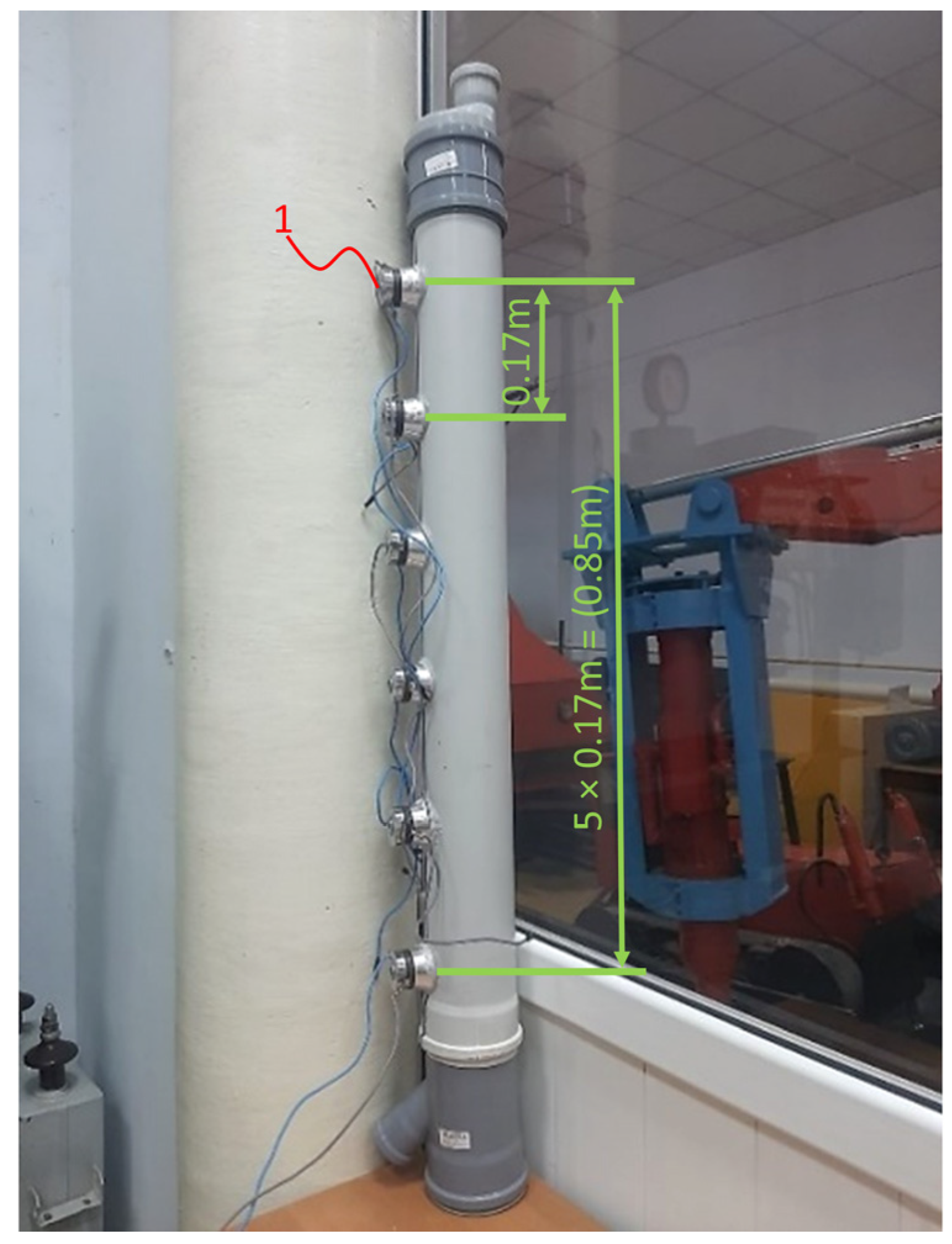
2.1. Exhaust Gas Cleaning System

In this study, a prototype of a vertical ultrasonic muffler stand was used (Figure 1). The stand was constructed from high-temperature-resistant plastic to withstand high temperatures and aggressive components of exhaust gases. The muffler featured a cylindrical design with an inner diameter of 102 mm and a height of 1300 mm, allowing for the installation of six levels of ultrasonic emitters spaced 0.17 m apart. The primary functional components were ultrasonic emitters, specifically the Ultrasonic Transducer 100 W model (Langevin type), manufactured by Guangzhou ZJS Ultrasonic Co., Ltd. (Guangzhou, China). Each emitter had a maximum power output of 100 W, arranged along the vertical axis of the test stand (Table 1). In total, there were 6 ultrasonic emitters positioned along the vertical axis of the test rig. This arrangement ensured that the exhaust gas passed through several treatment zones created by the emitters. Each zone contributed to the coagulation of particles, enhancing particle deposition as the gas moved downward. Thanks to this emitter arrangement, it was possible to adjust the power of each emitter depending on the height, flow velocity, or gas temperature. For example, the upper emitters could operate at maximum power to treat the incoming gas, while the lower emitters could operate at lower power to provide additional refinement.

2.2. Research Object

This research was conducted using the diesel engine of an MTZ-80 (Minsk, Belarus) tractor (manufactured in 1986, with a displacement of 4750 cm3). The technical specifications of the engine are provided in Table 2 and those of the tractor in Table 3.

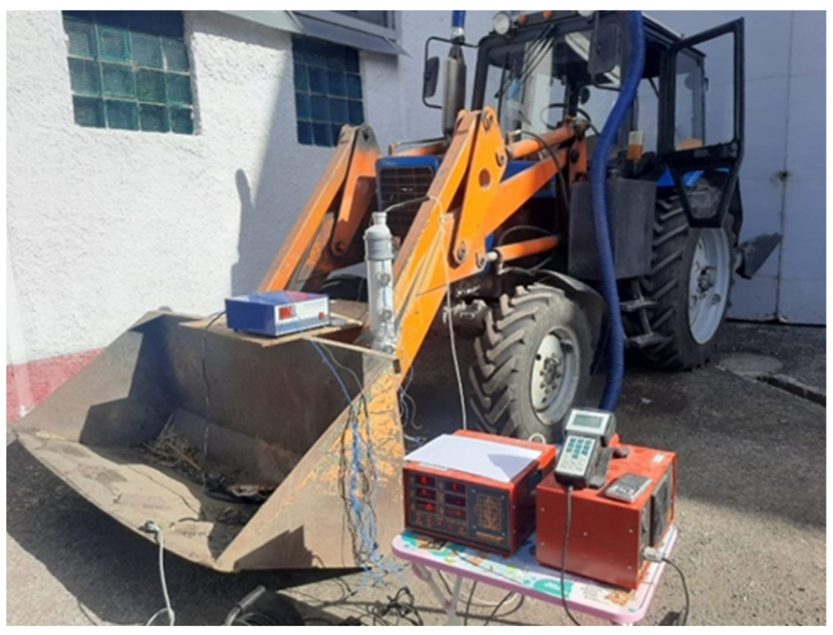
2.3. Research Stand, Plan, and Procedure for Conducting the Experiments

The experimental setup consisted of a tractor with its exhaust system tightly connected to a vertically mounted ultrasonic exhaust gas purification unit. The smoke density was measured at the outlet of the system using an exhaust gas analyzer (Brand: Infrakar, Model: M-1.01, manufactured by Alfa-Dinamika LLC, Moscow, Russia) (Figure 2). The experimental studies were carried out on the diesel engine of the MTZ-80 tractor, a model commonly used in agricultural machinery. This choice was made due to the engine’s widespread application, making the reduction in its emissions both practical and highly relevant.
Experimental studies on the developed stand were conducted as follows. The methodology of the experiment involved evaluating the effectiveness of ultrasonic influence on the exhaust gas smoke level of a diesel engine under different operating modes.
For this, a comparative measurement of smoke levels was carried out both without ultrasonic influence and with its application, taking into account various combinations of ultrasonic emitter connections and changes in engine crankshaft speed.
The experiments were conducted in two stages:
-
The first stage involved determining the baseline values of the exhaust gas smoke without ultrasonic influence, establishing the initial level of pollutant emissions.
-
The second stage involved conducting measurements with activated ultrasonic emitters, varying their configurations and connection order to identify the most effective operating mode.
The frequency and power of the ultrasonic emitters remained fixed.
The measurements were conducted in real time at various engine operating modes (1000, 1500, and 2000 rpm), under no-load (idle) conditions, which provided an objective assessment of the impact of the ultrasonic treatment on exhaust emissions.
The experimental research on the developed ultrasonic muffler stand was carried out according to a pre-prepared plan, as presented in Figure 3.
The experimental plan included step-by-step connection of the ultrasonic emitters in various combinations, which allowed for the identification of their impact on the exhaust gas smoke levels of a diesel engine:
  • Baseline stage (control measurement): Initially, the exhaust gas smoke levels were measured without ultrasonic exposure (experiment 1). This allowed for the determination of the baseline level of pollutant emissions, which was used as a reference for comparison.
  • Individual emitter activation stage: At this stage, individual emitters were activated one by one (experiments 2–4) to evaluate the specific contribution of the effect of each emitter on particle coagulation and the reduction in exhaust gas smoke levels.
  • Combined connection stage: Next, experiments were conducted in which various combinations of two or more emitters were activated (experiments 5–8). The goal of this stage was to identify the most effective emitter configurations for maximizing the reduction in PM in the exhaust gas flow.
  • Maximum power stage: In the final stage of the experiment (experiment 9), all six ultrasonic emitters were activated simultaneously. This mode allowed for the assessment of the maximum acoustic effect on PM particles and determined whether the optimal reduction in exhaust gas smoke levels was achieved with this configuration.
The developed plan allowed for the completion of all necessary experiments and the acquisition of reliable results regarding the influence of ultrasonic exposure on the coagulation and deposition of PM particles in the exhaust gases of a diesel engine.

3. Results and Discussion

3.1. Results of Experimental Studies

During the experiments, quantitative measurements of the exhaust smoke density were obtained at different engine speeds (1000, 1500, and 2000 rpm), both without ultrasonic exposure and under various ultrasonic emitter operating modes. The results of the experimental studies are presented in Figure 4. The obtained experimental results confirm that the use of ultrasound had a positive effect on reducing the smoke opacity levels of the exhaust gases, indicating the potential effectiveness of this cleaning method. Although the reduction in smoke opacity is less pronounced with increasing engine speed, this was due to the higher gas flow velocity and the need to establish the optimal configuration of ultrasonic emitters and their power levels. The highest smoke density was observed when the engine operated without ultrasonic influence, confirming the high level of pollutant emissions in the absence of ultrasonic particle coagulation. When individual emitters (experiments 2, 3, and 4) were connected, a slight reduction in smoke density was observed, but the effect remained insignificant. This is attributed to the localized nature of ultrasonic influence—certain areas in the gas flow are not subjected to coagulation.
A significant reduction in smoke density was observed when two or more emitters were activated simultaneously. The configurations used in experiments 5, 6, and 7 show a pronounced decrease in smoke levels, indicating a more uniform distribution of ultrasonic impact within the gas flow. However, even with three active emitters (1, 3, and 6) in experiment 8, a noticeable level of smoke density remained, suggesting the need for further optimization of the acoustic treatment to achieve optimal results.
The lowest level of pollution was recorded when all ultrasonic emitters were activated simultaneously (experiment 9). In this mode, a uniform ultrasonic field was created, encompassing the entire exhaust gas stream and ensuring maximum coagulation of PM particles and their effective deposition.
It should also be noted that at low engine speeds of 1000 rpm, the slower gas flow increased the residence time of the ultrasonic waves on the particles, promoting their effective coagulation.
At medium engine speeds of around 1500 rpm, the flow velocity increased, reducing the time that particles were in contact with the ultrasonic field. At the same time, the turbulence increased, which, on the one hand, contributed to the mixing of the gas and increased the likelihood of particle interaction with ultrasonic waves, but, on the other hand, may have hindered their coagulation. Despite this, when all emitters were fully activated, a significant reduction in smoke density was observed, although the effect was less pronounced compared to that at low engine speeds.
At high engine speeds of around 2000 rpm, the gas flow became very fast, substantially reducing the residence time for ultrasonic exposure. Under these conditions, the turbulence intensified, resulting in chaotic particle movement, which can both facilitate coagulation and break up already formed aggregates. The maximum reduction in smoke density was again achieved when all emitters were activated, as this provided the most powerful and uniform coverage by the ultrasonic field.
Therefore, to improve the gas cleaning efficiency at high engine speeds, it is recommended to increase the power of the emitters, optimize their placement or the distance between them, and consider the implementation of multi-stage gas treatment.

3.2. Results of the Conducted Regression–Correlation Analysis

Based on the results of the experimental studies, regression–correlation analysis (1) was carried out, during which a multiple regression equation was developed to describe the change in the gas opacity indicators as a function of the engine speed, the power of the ultrasonic emitters, and the distance between the emitters.
D = 91.7879 + 0.1175 × N + 23.2307 × L + 0.0263 × n + 0.0001 × N 2 + 0.0394 × N × L 10 7 × N × n + 20.5010 × L 2 + 0.0016 × L × n + 10 7 × n 2
where D is the PM density (by experiment), %; N is the power, W; L is the distance between the emitters, m; n is the engine speed, rpm.
The obtained value of the coefficient of determination (R2 = 0.9715) from the regression equation indicates that the multiple regression model effectively captures the relationship between the opacity of the exhaust gases and the engine speed, power of the ultrasonic emitters, and the distance between the emitters. This model is reliable for describing the cleaning process within these limits.
Furthermore, the obtained correlation coefficient (r = 0.98) indicates a strong linear relationship between the predicted values from the model and the actual experimental data. This indicates that the model reliably reflects the variations in opacity resulting from changes in engine speed, emitter power, and spacing.
According to the obtained regression equation, the values of opacity were determined for each combination of emitter activation. Based on the obtained opacity values, their deviation from the experimental values was calculated. The results of the calculation are presented in Figure 4.
According to Table 4, the approximation error shows that, on average, the regression model predictions deviated from the experimental data by 1.54%. The largest deviation was recorded for experiment 7 at 1500 rpm (4.01%), while the smallest was at 2000 rpm without ultrasonic impact (only 0.03%) (experiment 1). This proves that the regression model can be used to predict changes in opacity depending on the parameters of ultrasonic impact. This level of error is associated with the small number of experimental trials, which limits the model’s accuracy.
Therefore, to reduce the approximation error, it was necessary to increase the number of experimental tests.
The graph in Figure 5 reflects how accurately the regression model describes the exhaust gas cleaning process using ultrasound and how the experimental data correspond to the theoretical calculations. A comparison with the regression equation demonstrates that the calculated model matches the experimental data with a small deviation. This deviation may be due to experimental conditions, such as the inhomogeneity of pollutants or the dynamics of their removal, which were not fully accounted for in the model. The graphs also emphasize the importance of uniform ultrasound impact. Indeed, a uniform ultrasound effect throughout the length of the experimental stand led to lower opacity values.
Therefore, the proposed regression model can be used to predict cleaning results. However, to achieve the maximum cleaning effect, further optimization of parameters such as the distance between emitters and their power is required, since, in some cases, reducing the distance between them yields better results.

3.3. Results of the Mathematical Analysis of the Regression Equation

To establish the optimal values of the parameters, such as the distance between the emitters and their power, a mathematical analysis of the equation was conducted based on the regression model. The analysis allowed us to determine how changes in the engine speed (n), power (N), and the distance between the emitters (L) affected the PM density (D) values.
According to this analysis, partial derivatives of the equation were determined, which made it possible to establish the rate of change in PM density (D) when varying n, N, and L:
Regarding power (N):
d D d N = 0.0394 × L + 0.0002 × N 0.1175 .
Regarding distance (L):
d D d L = 41.002 × L + 0.0394 × N 0.0016 × n + 23.2307 .
Regarding the number of revolutions (n):
d D d n = 0.0016 × L 0.0263 .
Next, the critical points of the equation were determined, under the condition that:
d D d N = 0 ,
and
d D d L = 0 ,
and
d D d n = 0 .
Based on the obtained derivatives, it follows that an increase in power N reduced the smoke emissions (due to the negative linear term −0.1175). However, this influence decreased with larger values of L, as the interaction term (0.0394 × L) weakened the effect. The distance L had a strong negative influence on the smoke emissions (−41.002 × L).
Increasing the number of revolutions reduced the smoke emissions, but the effect was weak, as the coefficients were small (−0.0016 and −0.0263). The interaction with distance L also (−0.0016 × L) added a negligible influence on the smoke emissions.
Next, the critical points of the equations were determined under the conditions that the values of Equations (5) and (7) are equal to zero.
The solution to the system of equations was
0.0394 × L + 0.0002 × N 0.1175 = 0 41.002 × L + 0.0394 × N 0.0016 × n + 23.2307 = 0 0.0016 × L 0.0263 = 0
This allowed us to obtain the critical values of the parameters: N = 3825.69, L = 16.4375, and n = 529,958.23.
However, the values of the critical points lie outside the real ranges, making this point physically insignificant. In this case, the critical point has no practical application. This is because the regression model describes parameters within a limited range, and the mathematical analysis yields extreme values.
The second derivative of the equation describes the nature of the critical point:
For power:
d 2 D d N 2 = 0.0002 .
Regarding distance:
d 2 D d L 2 = 41.002 .
Regarding the number of revolutions:
d 2 D d n = 0 ,
d 2 D d N d L = 0.0394 ,
d 2 D d N d n = 0 ,
d 2 D d L d n = 0.0016 .
According to the calculated Hessian determinant H = −0.00000305, it is negative (H < 0), indicating a saddle point. This means that the function behaves differently in different directions. The saddle point confirms that the parameters (N, L, n) have opposite effects on the smoke density in different directions, and it is necessary to find a balance. Therefore, for maximum cleaning efficiency, the distance L between the emitters must be optimized, as both too small and too large values can lead to an increase in exhaust smoke. Additionally, it is important to consider the effect of power N, but its increase should be balanced with the optimal placement of the emitters. This balance between the distance L and power N was the key factor in minimizing the smoke density, while the number of revolutions n had a less significant impact on the process efficiency.
Based on the above and according to the system of Equation (8), the calculation for determining the optimal values of parameters L and N was performed using the following system of equations:
0.0394 × L + 0.0002 × N 0.1175 = 0 41.002 × L + 0.0394 × 900 0.0016 × n + 23.2307 = 0
Tractors operate within a wide range of engine revolutions during their use, varying from 800 to 2200 rpm depending on the tasks being performed. For transport operations, such as cargo transportation and road movement, higher revolutions are typical, from 1800 to 2200 rpm. At the same time, for fieldwork, such as plowing, cultivating, and seeding, the optimal range is 1400–1800 rpm, which ensures the necessary traction with economical fuel consumption.
Taking this into account, the calculation of the optimal parameters for power and the distance between emitters was conducted at an operating mode of 1800 rpm. As a result, the following values were obtained: power N = 319.35 W; distance between emitters L = 1.361 m. These parameters ensure the effective reduction in exhaust gas smoke at the specified engine operating conditions.

3.4. Recommendations for Adjusting the Parameters of the Ultrasonic Muffler

The analysis of the obtained data indicates that the efficiency of ultrasonic exhaust gas cleaning largely depends on ultrasonic emitter power (N) and the spacing between emitters (L). As the engine speed increases, the exhaust gas flow velocity rises, necessitating higher ultrasonic power to compensate for the reduced interaction time between particles and ultrasonic waves. At the same time, with higher flow speeds, the optimal distance between the emitters decreases, as a denser arrangement facilitates more effective particle interaction with the particles, preventing them from exiting the muffler without coagulation.
These findings suggest that optimizing the ultrasonic cleaning process requires dynamic adjustment of both the emitter power and spacing based on the engine’s operating conditions, specifically considering the engine speed and exhaust flow characteristics. Balancing these parameters ensures more efficient particle coagulation and PM reduction in the exhaust gases.
Based on the regression model, the optimal power for effective impact at 1800 rpm is N = 319.35 W. Given this, when using two emitters, their power should be approximately 160 W each. However, for improved exhaust flow coverage and enhanced coagulation efficiency, the use of three emitters is preferable, each operating at 100–110 W and spaced 0.8–0.9 m apart. This setup allows for a stepwise treatment of PM particles, impacting them at different levels and increasing the efficiency of their deposition.
Additionally, for maximum reduction in smoke levels, the silencer design can be further improved by adjusting the frequency and amplitude of the ultrasonic waves, enabling better adaptation to various engine operating modes. Furthermore, the use of multiple emitter levels in a vertical configuration will enable staged gas cleaning, reducing the likelihood of previously coagulated particles re-entering the gas stream.
The use of such a silencer is relevant not only for passenger vehicles but also for trucks, agricultural machinery, and stationary diesel installations, where the issue of reducing harmful emissions remains an ongoing challenge. Moreover, the design can be adapted to different engine types by adjusting the emitter power and positioning according to specific operating conditions. This makes the ultrasonic silencer a flexible and promising solution for smoke reduction in a wide range of transportation and industrial applications.

3.5. Discussion of the Results in the Context of Previous Studies

The results of this study confirm the effectiveness of ultrasonic exposure in reducing the smoke emissions of diesel engine exhaust gases, supporting previous findings on the use of physical methods for gas purification. In particular, the studies by Kadyrov A.S. et al. in 2021 and 2022 showed that ultrasound facilitates the coagulation of solid particles and reduces the concentration of CO2, CO, and CH in the exhaust gases of both gasoline and diesel engines [43,47,48]. The present work complements these studies by showing that the efficiency of ultrasonic exhaust purification is strongly influenced by the emitter placement and power—two critical factors in optimizing the overall cleaning performance.
One of the key distinctions of the presented study is the development and testing of a vertical ultrasonic muffler, whereas previous research has primarily focused on horizontal designs. The analysis of the results confirms that the vertical arrangement of ultrasonic emitters enhances the deposition of coagulated particles due to the force of gravity. This is in line with the theoretical expectations, as the vertical design minimizes the likelihood of re-entraining coagulated particles into the gas stream, unlike horizontal setups, where PM remains in a suspended state.
Additionally, it was established that as the engine speed increases, the cleaning efficiency decreases, primarily due to the reduced time that the particles interact with the ultrasonic field. This confirms the findings made in the works of Kadyrov et al. in 2024, where it was noted that to maintain high cleaning efficiency at high speeds, an increase in the power of the emitters is necessary [44]. The results also prove that the use of multiple ultrasonic emitters with stepped placement is a more effective approach compared to single emitters, as demonstrated by the experimental studies of previous authors.
Furthermore, research on the use of ultrasound can be extended along the direction proposed by He et al. (2023), who demonstrated that ultrasonic waves can be used to blend fuels such as ethanol and diesel in real time. This method has been shown to significantly reduce smoke emissions at medium and full loads, with reductions reaching up to 74% compared to pure diesel [49].

3.6. Limitations of the Study

This study demonstrated that a vertical ultrasonic muffler is an effective method for reducing exhaust smoke from diesel engines. The developed regression model enabled the identification of the optimal ultrasonic emitter operating parameters. According to this model, at an engine speed of 1800 rpm, the best results were achieved with a power of 319.35 W and a distance of 1.361 m between the emitters. It was established that increasing the power of the ultrasonic emitters and optimizing their spatial arrangement significantly reduced the concentration of PM in the exhaust gases.
However, the study has several limitations. First, the experiments were conducted within a limited engine speed range (1000–2000 rpm), which necessitates further testing to evaluate the method’s effectiveness at higher gas flow velocities. Second, the model considers linear relationships between parameters, but nonlinear effects, such as turbulence and the disintegration of particle clusters due to high gas speeds, require further investigation. Additionally, the experimental studies used fixed frequency and emitter power, while dynamic adjustment based on real-time engine operating conditions could enhance the efficiency of the cleaning process.
In the future, it is planned to expand the range of studies, including various types of diesel engines, and to adapt the model to real operating conditions. Additionally, the development of an automatic control system for ultrasonic emitters is expected, enabling the real-time adjustment of the power and positioning based on the current engine operating mode.

4. Conclusions

This study assessed the effectiveness of ultrasonic exposure in reducing diesel engine smoke emissions and identified the optimal parameters for an ultrasonic silencer. The results confirm that ultrasonic treatment significantly lowered the smoke levels, especially with increased emitter power, reduced spacing, and uniform acoustic distribution, as validated by a regression model showing optimal performance at 319.35 W and a spacing of 1.361 m. The vertical silencer design additionally improved the particle removal by preventing soot re-entrainment. Although limited to a narrow engine speed range and a linear model, the findings offer a valuable contribution to emission reduction methods. Future work will explore broader engine conditions and intelligent emitter control to enhance the applicability across various diesel systems.

Author Contributions

Conceptualization, A.K. (Adil Kadyrov), A.K. (Aliya Kukesheva), Y.D. and Ł.W.; methodology, A.K. (Adil Kadyrov), A.K. (Aliya Kukesheva), Y.D. and Ł.W.; software, A.K. (Adil Kadyrov), A.K. (Aliya Kukesheva) and Y.D.; validation, A.K. (Adil Kadyrov), A.K. (Aliya Kukesheva), Y.D. and Ł.W.; formal analysis, A.K. (Adil Kadyrov), A.K. (Aliya Kukesheva), Y.D. and Ł.W.; investigation, A.K. (Adil Kadyrov), A.K. (Aliya Kukesheva), Y.D., W.K., P.K., B.W. and Ł.W.; resources, A.K. (Adil Kadyrov), A.K. (Aliya Kukesheva), Y.D., W.K., P.K., B.W. and Ł.W.; data curation, A.K. (Adil Kadyrov), A.K. (Aliya Kukesheva), Y.D. and Ł.W.; writing–original draft preparation, Ł.W., A.K. (Adil Kadyrov), A.K. (Aliya Kukesheva) and Y.D.; writing–review and editing, Ł.W., A.K. (Adil Kadyrov), A.K. (Aliya Kukesheva) and Y.D.; visualization, Ł.W., B.W., A.K. (Adil Kadyrov), A.K. (Aliya Kukesheva) and Y.D.; supervision, Ł.W.; project administration, A.K. (Adil Kadyrov), A.K. (Aliya Kukesheva) and Y.D.; funding acquisition, A.K. (Adil Kadyrov), A.K. (Aliya Kukesheva), Y.D., W.K. and P.K. All authors have read and agreed to the published version of the manuscript.

Funding

Funding for the publication of this article was provided through a subvention from the Ministry of Science and Higher Education, category: other scientific activities.

Institutional Review Board Statement

Not applicable.

Informed Consent Statement

Not applicable.

Data Availability Statement

All data supporting the reported results are included in the manuscript.

Conflicts of Interest

The authors declare no conflicts of interest.

Abbreviations

The following abbreviations are used in this manuscript:
COCarbon monoxide
CO2Carbon dioxide
DOCDiesel oxidation catalysts
DPFDiesel particulate filters
EGRExhaust gas recirculation
HCHydrocarbons
H2SHydrogen sulfide
NOxNitrogen oxides
PMParticulate matter
SCRSelective catalytic reduction

References

  1. Tucki, K.; Orynycz, O.A.; Świć, A.; Wasiak, A.; Mruk, R.; Gola, A. Analysis of the Possibility of Using Neural Networks to Monitor the Technical Efficiency of Diesel Engines During Operation. Adv. Sci. Technol. Res. J. 2023, 17, 1–15. [Google Scholar] [CrossRef]
  2. Smigins, R.; Skrzek, T.; Górska, M.; Pawlak, G. Investigation of Harmful Chemical Compounds from Dual-Fuelled Diesel Engine. Adv. Sci. Technol. Res. J. 2020, 14, 21–29. [Google Scholar] [CrossRef]
  3. Chwist, M.; Gruca, M.; Pyrc, M.; Szwaja, M. By-Products from Thermal Processing of Rubber Waste as Fuel for the Internal Combustion Piston Engine. Combust. Engines 2020, 181, 11–18. [Google Scholar] [CrossRef]
  4. Feng, R.; Yu, J.; Shu, X.; Deng, B.; Hua, Z. Can the World Harmonized Steady Cycle (WHSC) Accurately Reflect Real-World Driving Conditions for Heavy-Duty Diesel Engine Emission Valuations? A Comprehensive Experimental Study. Therm. Sci. Eng. Prog. 2025, 59, 103321. [Google Scholar] [CrossRef]
  5. Mohankumar, S.; Senthilkumar, P. Particulate Matter Formation and Its Control Methodologies for Diesel Engine: A Comprehensive Review. Renew. Sustain. Energy Rev. 2017, 80, 1227–1238. [Google Scholar] [CrossRef]
  6. Joshi, A. Review of Vehicle Engine Efficiency and Emissions. SAE Int. J. Adv. Curr. Prac. Mobil. 2020, 2, 2479–2507. [Google Scholar] [CrossRef]
  7. Rymaniak, Ł.; Lijewski, P.; Kamińska, M.; Fuć, P.; Kurc, B.; Siedlecki, M.; Kalociński, T.; Jagielski, A. The Role of Real Power Output from Farm Tractor Engines in Determining Their Environmental Performance in Actual Operating Conditions. Comput. Electron. Agric. 2020, 173, 105405. [Google Scholar] [CrossRef]
  8. Warguła, Ł.; Lijewski, P.; Kukla, M. Effects of Changing Drive Control Method of Idling Wood Size Reduction Machines on Fuel Consumption and Exhaust Emissions. Croat. J. For. Eng. (Online) 2023, 44, 137–151. [Google Scholar] [CrossRef]
  9. Sobczak, J.; Kamińska, M.; Ziółkowski, A.; Rymaniak, Ł.; Szymlet, N. Analysis of Pollutant Emissions of a Railbus Based on Real Train Emissions Measurements. Combust. Engines 2025, 201, 22–33. [Google Scholar] [CrossRef]
  10. Puzdrowska, P. Comparison of Methods for Diagnosing Marine IC Engines Based on Working Medium Parameters Including Exhaust Gas Specific Enthalpy. Combust. Engines 2024, 201, 3–13. [Google Scholar] [CrossRef]
  11. Sassykova, L.; Nalibayeva, A.; Aubakirov, Y.; Tashmukhambetova, Z.; Otzhan, U.; Zhakirova, N.; Faizullaeva, M. Preparation and Study of Catalysts on Metal Blocks for Neutralization of Exhaust Gases of the Stationary Diesel Generator. Orient. J. Chem. 2017, 33, 1941–1948. [Google Scholar] [CrossRef]
  12. Liu, H.; Wang, Z.; Wang, J.; He, X. Improvement of Emission Characteristics and Thermal Efficiency in Diesel Engines by Fueling Gasoline/Diesel/PODEn Blends. Energy 2016, 97, 105–112. [Google Scholar] [CrossRef]
  13. Zimakowska-Laskowska, M.; Kozłowski, E.; Laskowski, P.; Wiśniowski, P.; Świderski, A.; Orynycz, O. Vehicle Exhaust Emissions in the Light of Modern Research Tools: Synergy of Chassis Dynamometers and Computational Models. Combust. Engines 2025, 200, 145–154. [Google Scholar] [CrossRef]
  14. Rimkus, A.; Kozłowski, E.; Vipartas, T.; Pukalskas, S.; Wiśniowski, P.; Matijošius, J. Emission Characteristics of Hydrogen-Enriched Gasoline Under Dynamic Driving Conditions. Energies 2025, 18, 1190. [Google Scholar] [CrossRef]
  15. Sharma, R.; Kurmi, O.P.; Hariprasad, P.; Tyagi, S.K. Health Implications Due to Exposure to Fine and Ultra-Fine Particulate Matters: A Short Review. Int. J. Ambient. Energy 2024, 45, 2314256. [Google Scholar] [CrossRef]
  16. Fiordelisi, A.; Piscitelli, P.; Trimarco, B.; Coscioni, E.; Iaccarino, G.; Sorriento, D. The Mechanisms of Air Pollution and Particulate Matter in Cardiovascular Diseases. Heart Fail. Rev. 2017, 22, 337–347. [Google Scholar] [CrossRef] [PubMed]
  17. Dasadhikari, K. Attribution of PM2.5 Health Impacts in Asia-Pacific. Master’s Thesis, Massachusetts Institute of Technology, Cambridge, MA, USA, 2018. [Google Scholar]
  18. Hassan, N.E.; Rashid, H.A. Review of Toxic Gases and Their Impact on Human Health. Jabirian J. Biointerface Res. Pharmaceut. Appl. Chem. 2024, 1, 7–12. [Google Scholar] [CrossRef]
  19. Chen, C.; Yao, A.; Yao, C.; Wang, B.; Lu, H.; Feng, J.; Feng, L. Study of the Characteristics of PM and the Correlation of Soot and Smoke Opacity on the Diesel Methanol Dual Fuel Engine. Appl. Therm. Eng. 2019, 148, 391–403. [Google Scholar] [CrossRef]
  20. Duvvuri, P.P.; Sukumaran, S.; Shrivastava, R.K.; Sreedhara, S. Modeling Soot Particle Size Distribution in Diesel Engines. Fuel 2019, 243, 70–78. [Google Scholar] [CrossRef]
  21. DeMarini, D.M.; Linak, W.P. Mutagenicity and Carcinogenicity of Combustion Emissions Are Impacted More by Combustor Technology than by Fuel Composition: A Brief Review. Environ. Mol. Mutagen. 2022, 63, 135–150. [Google Scholar] [CrossRef]
  22. World Health Organization. WHO Global Air Quality Guidelines: Particulate Matter (PM2.5 and PM10), Ozone, Nitrogen Dioxide, Sulfur Dioxide and Carbon Monoxide; World Health Organization: Geneva, Switzerland, 2021; ISBN 978-92-4-003422-8. [Google Scholar]
  23. Alozie, N.S.I. Issues of Particulate Matter Emission from Diesel Engine and Its Control. Ph.D. Thesis, Brunel University, London, UK, 2016. [Google Scholar]
  24. Valeika, G.; Matijošius, J.; Rimkus, A. Research of the Impact of EGR Rate on Energy and Environmental Parameters of Compression Ignition Internal Combustion Engine Fuelled by Hydrogenated Vegetable Oil (HVO) and Biobutanol—Castor Oil Fuel Mixtures. Energy Convers. Manag. 2022, 270, 116198. [Google Scholar] [CrossRef]
  25. Tucki, K.; Mruk, R.; Orynycz, O.; Botwińska, K.; Gola, A.; Bączyk, A. Toxicity of Exhaust Fumes (CO, NOx) of the Compression-Ignition (Diesel) Engine with the Use of Simulation. Sustainability 2019, 11, 2188. [Google Scholar] [CrossRef]
  26. Lee, K.; Cho, H. Comparative Analysis of Performance and Emission Characteristics of Biodiesels from Animal Fats and Vegetable Oils as Fuel for Common Rail Engines. Energies 2024, 17, 1711. [Google Scholar] [CrossRef]
  27. Gao, J.; Chen, H.; Tian, G.; Ma, C.; Zhu, F. An Analysis of Energy Flow in a Turbocharged Diesel Engine of a Heavy Truck and Potentials of Improving Fuel Economy and Reducing Exhaust Emissions. Energy Convers. Manag. 2019, 184, 456–465. [Google Scholar] [CrossRef]
  28. Biswas, S.; Verma, V.; Schauer, J.J.; Sioutas, C. Chemical Speciation of PM Emissions from Heavy-Duty Diesel Vehicles Equipped with Diesel Particulate Filter (DPF) and Selective Catalytic Reduction (SCR) Retrofits. Atmos. Environ. 2009, 43, 1917–1925. [Google Scholar] [CrossRef]
  29. Li, J.; Li, G.; Sun, H.; Li, L.; Zheng, Z.; Yao, M. Development of the Two-Stage SCR Control Strategy to Satisfy Ultra-Low NOx Emission Regulation for Heavy-Duty Diesel Engine. J. Environ. Sci. 2025, 156, 360–370. [Google Scholar] [CrossRef] [PubMed]
  30. Thangaraja, J.; Kannan, C. Effect of Exhaust Gas Recirculation on Advanced Diesel Combustion and Alternate Fuels—A Review. Appl. Energy 2016, 180, 169–184. [Google Scholar] [CrossRef]
  31. Deng, B.; Cai, W.; Zhang, W.; Bian, L.; Che, X.; Xiang, Y.; Wu, D. A Comprehensive Investigation of EGR (Exhaust Gas Recirculation) Effects on Energy Distribution and Emissions of a Turbo-Charging Diesel Engine under World Harmonized Transient Cycle. Energy 2025, 316, 134506. [Google Scholar] [CrossRef]
  32. Stoeck, T. Problems of Regeneration of Modern Piezoelectric Fuel Injectors. Combust. Engines 2022, 61, 3–8. [Google Scholar] [CrossRef]
  33. Liu, S.; Zhang, Y. Research on the Integrated Intercooler Intake System of Turbocharged Diesel Engine. Int. J. Automot. Technol. 2020, 21, 339–349. [Google Scholar] [CrossRef]
  34. Naser, L.; Ilir, D.; Shpetim, L. Modelling and Simulation of the Turbocharged Diesel Engine with Intercooler. IFAC-PapersOnLine 2016, 49, 237–242. [Google Scholar] [CrossRef]
  35. Calam, A.; Solmaz, H.; Yılmaz, E.; İçingür, Y. Investigation of Effect of Compression Ratio on Combustion and Exhaust Emissions in A HCCI Engine. Energy 2019, 168, 1208–1216. [Google Scholar] [CrossRef]
  36. Feng, R.; Hu, X.; Li, G.; Sun, Z.; Deng, B. A Comparative Investigation between Particle Oxidation Catalyst (POC) and Diesel Particulate Filter (DPF) Coupling Aftertreatment System on Emission Reduction of a Non-Road Diesel Engine. Ecotoxicol. Environ. Saf. 2022, 238, 113576. [Google Scholar] [CrossRef] [PubMed]
  37. Zhang, Z.; Dong, R.; Lan, G.; Yuan, T.; Tan, D. Diesel Particulate Filter Regeneration Mechanism of Modern Automobile Engines and Methods of Reducing PM Emissions: A Review. Env. Sci. Pollut. Res. 2023, 30, 39338–39376. [Google Scholar] [CrossRef]
  38. Lin, D.; Zhang, L.; Liu, Z.; Wang, B.; Han, Y. Progress of Selective Catalytic Reduction Denitrification Catalysts at Wide Temperature in Carbon Neutralization. Front. Chem. 2022, 10, 946133. [Google Scholar] [CrossRef]
  39. Ferella, F. A Review on Management and Recycling of Spent Selective Catalytic Reduction Catalysts. J. Clean. Prod. 2020, 246, 118990. [Google Scholar] [CrossRef]
  40. Karre, A.V.; Garlapalli, R.K.; Jena, A.; Tripathi, N. State of the Art Developments in Oxidation Performance and Deactivation of Diesel Oxidation Catalyst (DOC). Catal. Commun. 2023, 179, 106682. [Google Scholar] [CrossRef]
  41. Caliskan, H.; Mori, K. Environmental, Enviroeconomic and Enhanced Thermodynamic Analyses of a Diesel Engine with Diesel Oxidation Catalyst (DOC) and Diesel Particulate Filter (DPF) after Treatment Systems. Energy 2017, 128, 128–144. [Google Scholar] [CrossRef]
  42. Kleinhenz, M.; Fiedler, A.; Lauer, P.; Döring, A. SCR Coated DPF for Marine Engine Applications. Top. Catal. 2019, 62, 282–287. [Google Scholar] [CrossRef]
  43. Kadyrov, A.S.; Sarsembekov, B.K.; Ganyukov, A.A.; Zhunusbekova, Z.Z.; Alikarimov, K.N. Experimental Research of the Coagulation Process of Exhaust Gases under the Influence of Ultrasound. Komunikácie 2021, 23, B288–B298. [Google Scholar] [CrossRef]
  44. Kadyrov, A.; Bembenek, M.; Sarsembekov, B.; Kukesheva, A.; Nurkusheva, S. The Influence of the Frequency of Ultrasound on the Exhaust Gas Purification Process in a Diesel Car Muffler. Appl. Sci. 2024, 14, 5027. [Google Scholar] [CrossRef]
  45. Pak, I.; Kadyrov, A.; Askarov, B.; Suleyev, B.; Karsakova, A. Developing and Studying the Method of Ultrasonic Purification and Utilization of Internal Combustion Engine Exhaust Gases. Komunikácie 2023, 25, B245–B258. [Google Scholar] [CrossRef]
  46. Kadyrov, A.; Ganyukov, A.; Pak, I.; Suleyev, B.; Balabekova, K. Theoretical and Experimental Study of Operation of the Tank Equipment for Ultrasonic Purification of the Internal Combustion Engine Exhaust Gases. Komunikácie 2021, 23, B219–B226. [Google Scholar] [CrossRef]
  47. Kadyrov, A.; Sarsembekov, B.; Ganyukov, A.; Suyunbaev, S.; Sinelnikov, K. Ultrasonic Unit for Reducing the Toxicity of Diesel Vehicle Exhaust Gases. Komunikácie 2022, 24, B189–B198. [Google Scholar] [CrossRef]
  48. Shalunov, A.V.; Bochenkov, A.S. Method for Increasing Efficiency of Ultrasonic Coagulation Due to Secondary Acoustic Effects. In Proceedings of the III International Conference on Advances in Science, Engineering, and Digital Education: Asedu-III 2022, Krasnoyarsk, Russian, 8–10 December 2022; AIP Publishing: Melville, NY, USA, 2024; Volume 2969. [Google Scholar]
  49. He, B.; Wang, J.; Yan, X.; Chen, H.; Tian, X. Combustion and Emission Characteristics of Engines Using Ethanol-Diesel Fuels Blended on Line. Qinghua Daxue Xuebao/J. Tsinghua Univ. 2003, 43, 1523–1525+1541. [Google Scholar]
Figure 1. Exhaust gas cleaning system; (1) ultrasonic emitter.
Applsci 15 07870 g001
Figure 2. Research stand.
Applsci 15 07870 g002
Figure 3. Experimental plan.
Applsci 15 07870 g003
Figure 4. Changes in the smoke density indicators depending on the combination of ultrasonic emitter connections and rotational speed engine.
Applsci 15 07870 g004
Figure 5. Comparison of the smoke indicators determined during the experimental tests and those calculated using the regression equation.
Applsci 15 07870 g005
Table 1. Technical specifications of the ultrasonic emitter.
ParameterValue
Operating (resonant) frequency40 kHz
Output power100 W
Static capacitance5200 ± 10% pF
Impedance at resonance≤20 Ω
Insulation resistance (at 2500 V DC)≥100 MΩ
Waveguide diameter (maximum)55 m
Waveguide diameter (minimum)45 mm
Piezo element diameter45 mm
Waveguide length24 mm
Total length of the transmitter46 mm
Female threadM10
Thread depth10 mm
Reflector thickness12 mm
Bandwidth~38–42 kHz
Radiation angle (beam width)approx. 45–60°
Table 2. Technical data of the tested engine.
ParameterValue
Engine make and modelD-243, Minsk Motor Plant (MMZ)
Manufacturer city and countryMinsk, Belarus (then part of the Union of Soviet Socialist Republics (USSR))
Installed inMTZ-80 tractor
Year of manufacture1986 (test sample)
Engine typeDiesel, 4-stroke, naturally aspirated
ConfigurationInline, 4 cylinders
Displacement4750 cm3
Bore × stroke110 × 125 mm
Power output59 kW (80 hp) at 2200 rpm
TorqueUp to 290 Nm at 1400–1600 rpm
Cooling systemLiquid-cooled
FuelDiesel
Emission standardNon-compliant with modern standards (no DPF, EGR, etc.)
Table 3. Technical data of the tested backhoe loader.
ParameterValue
Base machineMTZ-80 (Minsk Tractor Works)
Manufacturer city and countryMinsk, Belarus (then part of the USSR)
Model of backhoe loaderSelf-propelled machine based on MTZ-80 with front loader equipment
Year of manufactureApproximately 1986–1990
Type of machineMultifunctional backhoe loader
PurposeEarthworks, material handling, laboratory testing
Operating weight~6500–7500 kg (depending on attachments)
Transmission typeManual transmission with low-speed gears
Maximum speed~30 km/h
Loader equipmentFront bucket
(width ~1.9 m, capacity ~0.8 m3)
Additional equipmentCapability for rear excavator arm installation
Measurement equipment installedGas analyzer, power supply units, ultrasonic emitters, data acquisition units
Design featuresModified into a laboratory stand for exhaust gas treatment experiments
Table 4. Results of experimental studies.
ExperimentEngine Speed, rpmSmoke (by
Experiment) (D), %
Power of UE (N), WDistance Between Ultrasonic
Emitters
Smoke Density (According to the Regression
Equation) (D), %
Deviation, (%)
110007979.680.86
2731000.1773.690.95
3771000.3476.270.94
4791000.8576.882.67
5692000.3469.160.23
6702000.8571.782.54
7712000.5171.220.31
8673000.8567.971.45
9666000.8564.3142.55
115008784.33.1
2781000.1778.861.1
3801000.3481.291.62
4811000.8581.50.62
5742000.3474.861.17
6782000.8577.081.17
7802000.5176.794.01
8723000.8573.952.71
9716000.8572.321.87
120009696.030.03
2901000.1791.131.25
3911000.3493.432.67
4921000.8593.241.35
5892000.3487.681.48
6902000.8589.490.55
7912000.5189.471.67
8893000.8587.042.19
9876000.8587.450.52
Disclaimer/Publisher’s Note: The statements, opinions and data contained in all publications are solely those of the individual author(s) and contributor(s) and not of MDPI and/or the editor(s). MDPI and/or the editor(s) disclaim responsibility for any injury to people or property resulting from any ideas, methods, instructions or products referred to in the content.

