Article

Failure Mechanism and Structural Analysis of Chain Slings with Non-Standard Connections

1
Department of Mechanical Design and Manufacturing Engineering, Changwon National University, Changwon 51140, Republic of Korea
2
School of Mechanical Engineering, Changwon National University, Changwon 51140, Republic of Korea
*
Author to whom correspondence should be addressed.
Appl. Sci. 2025, 15(14), 7841; https://doi.org/10.3390/app15147841 (registering DOI)
Submission received: 11 June 2025 / Revised: 7 July 2025 / Accepted: 11 July 2025 / Published: 13 July 2025

Abstract

This study investigates the mechanical behavior and failure characteristics of chain slings under standard and non-standard fastening methods. Through dimensional inspections, fracture tests, and finite element analysis, we identified critical factors influencing chain failure. Chains exhibiting over 10% diameter reduction or increased pitch exceeded discard criteria and showed significant strength loss. Fracture loads in aged chains dropped by more than 35% compared to standards. Structural analysis revealed that standard fastening (using master links) ensures uniform stress distribution and higher load capacity, whereas non-standard fastening (direct wrapping on eyebolts) caused stress concentration, reduced tensile capacity by over 15%, and led to localized failure near contact areas. These results validate the structural soundness of international standards (DIN EN 818-4, ISO 3056) and highlight the risks of improper fastening. Practical recommendations include strict adherence to standard fastening methods, avoidance of direct wrapping, and implementation of regular inspections. The findings emphasize the need for design considerations regarding fastening geometry and suggest further research into fatigue life prediction and contact condition optimization.

1. Introduction

Chain hoists and chain slings are essential devices used for the stable and efficient lifting and handling of heavy loads, and they are widely employed across various industries such as manufacturing, construction, logistics, and shipbuilding. Their ability to safely move loads even in spatially constrained environments makes them highly versatile, and their importance lies in enhancing both operational efficiency and safety at worksites.
However, in industrial settings, safety regulations related to chain use are frequently neglected or poorly managed, leading to structural deficiencies in chain systems and subsequently increasing the risk of accidents. The safety of chain systems depends not only on material strength or manufacturing quality but also on a complex interplay of factors, including the geometric design of components, connection methods, loading conditions, usage frequency, and maintenance quality [1]. In particular, improper adherence to specifications such as sling angles, working methods, load limits, and safety factors can result in localized stress concentrations and permanent deformation, significantly increasing the risk of chain failure [2,3].
Nevertheless, non-standard connection practices—such as directly wrapping chains around eyebolts or hooks without using master links—are frequently observed in the field. Such practices adversely affect the structural integrity of the chain, alter stress transfer paths, and generate localized stress concentrations that may lead to unexpected fractures. Uneven stress distributions on the surface of chain links can also initiate fatigue cracks during repeated use, potentially leading to catastrophic system failure [4].
In addition, repeated use and aging of chain systems are major contributing factors to degradation. Chains that have been in service for extended periods often exhibit reduced durability due to accumulated damage such as wear, corrosion, and microcracking. Internal defects that are not visible to the naked eye can serve as critical weaknesses, causing sudden failure under overload conditions. Therefore, regular inspection and accurate life prediction are essential. Structural analysis, beyond simple visual inspections, is required to assess the chain’s true condition. Prior studies have also confirmed that long-term use and repeated repairs significantly contribute to failure [5].
Numerous researchers worldwide have conducted studies to better understand the failure mechanisms of chain systems, particularly focusing on fatigue life and related analyses. Zarandi et al. [6] investigated residual stresses in mooring chains using neutron diffraction, hole-drilling experiments, and finite element analysis, revealing that residual stresses significantly affect fatigue crack initiation and fatigue life. Lone et al. [7] developed a probabilistic S–N based fatigue model incorporating mean load and corrosion effects, proposing a reliability assessment method for the design and life extension of mooring chains. Zhang et al. [8] evaluated the fatigue performance of large-diameter, high-strength offshore mooring chains under seawater conditions through full-scale testing. Fernández et al. [9] and Gabrielsen et al. [10] experimentally examined the effects of mean load on the fatigue life of chains with varying diameters and grades, finding that increased mean loads result in reduced fatigue life. Bergara et al. [11] validated fatigue crack propagation in offshore mooring chains by combining experiments, finite element analysis, and analytical SIF-Paris law, including residual stresses induced by proof loading during manufacturing, clearly demonstrating the significant influence of residual stresses on crack growth behavior. Lone et al. [12] analyzed the impact of mean load and corrosion on the fatigue life of mooring chains and proposed an extended S-N curve model incorporating these effects. Kim et al. [13] conducted fatigue analyses that considered both out-of-plane bending (OPB) and in-plane bending (IPB), allowing for a quantitative assessment of fatigue damage. Lone et al. [14] developed a reliability-based fatigue damage prediction model based on S–N curves that includes degradation effects from mean load and corrosion, enabling quantitative assessment of the fatigue failure probability of mooring chains. Zarandi et al. [15] experimentally evaluated the low-cycle fatigue behavior of mooring chains made from R4 high-strength steel under varying strain amplitudes and strain ratios, and elucidated the fatigue damage accumulation mechanisms using strain energy-based damage indicators. Qvale et al. [16] experimentally evaluated the effects of natural corrosion on fatigue crack growth and remaining fatigue life of mooring chain steel, revealing that corrosion does not significantly impact fatigue life. Aursand et al. [17] applied crack growth modeling to assess the remaining fatigue life of corroded mooring chains and quantitatively analyzed the impact of corrosion on fatigue life. Lone et al. [18] analyzed S–N data for new and corroded mooring chains under various mean load conditions to evaluate the effects of mean load and corrosion level on the fatigue life of mooring chains. Pressas et al. [19] conducted chemical and fractographic analyses on failed chains, identifying coarse carbides as a primary failure cause, and used finite element analysis (FEA) to predict stress concentration sites and fatigue life. Gabrielsen et al. [20] evaluated the effects of fatigue, corrosion, and loading conditions on chain performance through fatigue testing of mooring chains.
Several other studies have examined the stress distribution and mechanical properties of chains depending on their configuration and fastening conditions. Zarandi et al. [21] used neutron diffraction and hole drilling methods to measure residual stresses in mooring chains, validating stress redistribution under corrosion and cyclic loading through FEA. Park et al. [22] used nonlinear FEA to analyze the structural strength of steel chains in contact with knuckle-type plates, suggesting the need for optimal designs that account for stress mitigation, material properties, and angular conditions. Kim et al. [23] investigated how installation conditions influence stress distribution, showing that improper installation can lead to localized stress concentrations and eventual failure. Angulo et al. [24] applied finite element analysis (FEA) to simulate crack initiation and growth in mooring chains for offshore structures and evaluated the potential of combining ultrasonic guided waves (UGW) and acoustic emission (AE) techniques for damage detection and localization. Cheng et al. [25] analyzed the microstructure and mechanical properties of chain steels subjected to tempering at various temperatures.
Failure case studies have also been conducted to identify root causes and support design improvements. Ma et al. [26] investigated permanent mooring system failures, revealing the structural weaknesses of components and unexpected failure mechanisms, and highlighting the limitations of existing design criteria and the need to improve integrity management. Riccioli et al. [27] evaluated the feasibility of detecting, locating, and monitoring corrosion-fatigue damage in studless R4 mooring chains operated offshore for about 20 years using non-contact underwater acoustic emission (AE) technology.
Furthermore, research has actively addressed safety policies related to slinging operations and improvements in chain design. Lee et al. [28] compared domestic and international regulations to enhance the safety of lifting chain slings used in industry and proposed improvements based on accident case studies. Yeom et al. [29] emphasized the need for certification systems for rigging and slinging operations to reduce falling object accidents on construction sites. Lee et al. [30] highlighted the higher risks of offshore rigging and slinging operations compared to land-based work and proposed the development of training programs to improve worker safety. Fontaine et al. [31] reviewed failure cases, preemptive replacements, and degradation phenomena across the mooring industry, emphasizing the importance of chain integrity management.
These prior studies have contributed significantly to improving the safety of mooring chains by elucidating the effects of cyclic loading, corrosion, and residual stresses on fatigue life and structural integrity. However, research remains insufficient regarding the specific effects of non-standard connections—such as the direct attachment of chains to eyebolts without master links—and the impact of long-term use and aging frequently observed in real-world industrial environments. Non-standard connections are known to alter stress concentration patterns and deformation behaviors within the chain, thereby increasing the risk of fatigue failure. Yet, quantitative analyses of such effects are still rare. Similarly, experimental and analytical approaches to understanding the initiation and propagation of microcracks in aged chains are limited. Therefore, ensuring structural stability and durability under these conditions is an essential task for improving safety in the field.
In this study, we analyze real-world chain failure cases to identify the root causes and mechanical behavior changes. Through failure testing, the durability of the chains is experimentally validated, and finite element analysis (FEA) is conducted to systematically assess structural changes under non-standard usage conditions, specifically when chains are directly connected to eyebolts without master links. FEA is a widely used tool that precisely predicts stress distribution and deformation characteristics, allowing identification of potential failure sites and areas of stress concentration within chain components. Using this approach, the complex load conditions and connection configurations commonly encountered in industrial settings are quantitatively evaluated for their effects on chain durability and failure potential. Based on the findings, the study aims to propose practical and specific guidelines for improving the safe use of chains in industrial environments, ultimately contributing to worker safety and accident prevention.

2. Overview

Figure 1 presents a case of an industrial accident in which two lifting chains fractured simultaneously during the unloading of a heavy load. The incident occurred under non-standard rigging conditions, where the chain slings were directly wrapped around and connected to a hook and an eye bolt, instead of using the standard connection methods involving master links or shackles. Such non-standard practices, although clearly deviating from recommended safety guidelines, are frequently observed in industrial settings due to spatial constraints or for the sake of operational convenience.
As illustrated in Figure 2, wrapping a chain directly around an eye bolt or hook introduces abnormal bending loads and circumferential stresses on the chain links. Furthermore, this type of connection leads to unbalanced load distribution at the contact points, resulting in localized deformation and stress concentration. Particularly, when the chain is subjected to repeated torsional stresses in combination with bending, rapid failure may occur even when the applied load does not exceed the design tensile strength or rated breaking load.
In this accident case, the lifting chains had been reused without undergoing appropriate maintenance procedures such as visual inspection or dimensional checks. Due to deformation and reduced durability caused by the non-standard connection method, the chains ultimately fractured under the weight of the load. Therefore, to ensure the structural stability of chain slings and prevent failure, it is essential to use standard connection devices that distribute loads evenly during rigging operations. Specifically, methods involving direct wrapping of chains around cargo, eye bolts, or hooks distort the intended load transfer paths and should be avoided, as they can lead to premature failure well before the chain reaches its expected service life.
Based on this accident case, the present study aims to analyze the root causes of chain failure and quantitatively investigate the structural issues that may arise under non-standard usage conditions.

3. Failure Cause Analysis

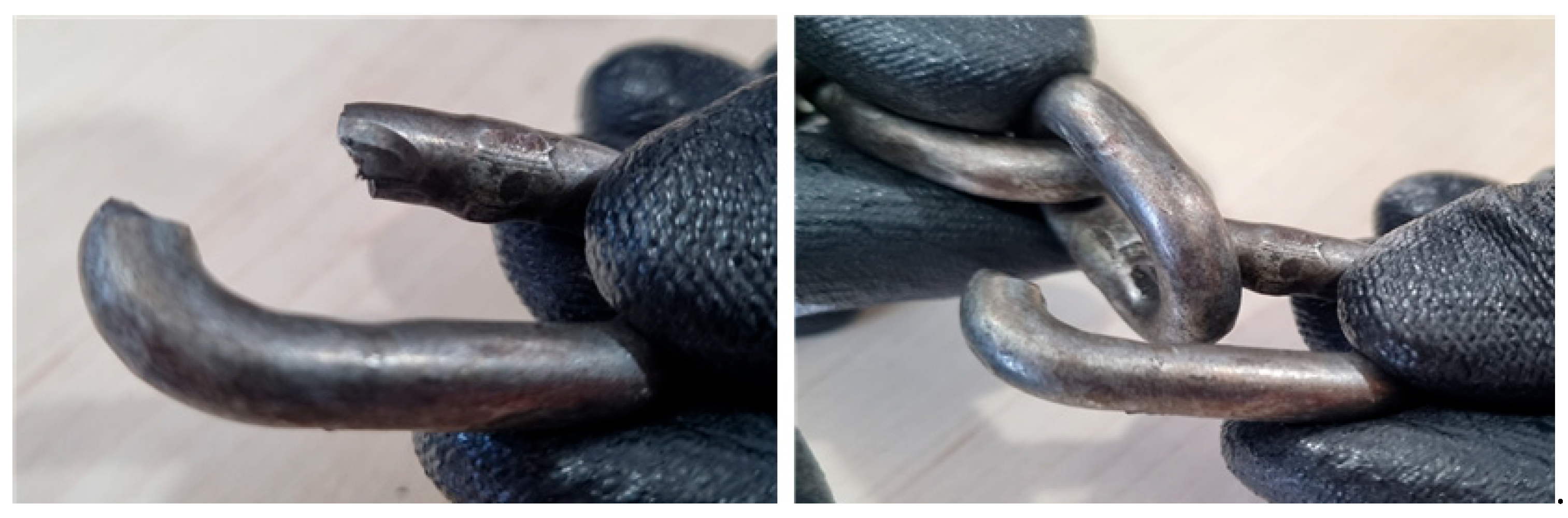
3.1. Fracture Surface Analysis

The fracture surfaces of the two failed chains are shown in Figure 3. Although both chains had identical specifications, their fracture surface morphologies exhibited distinct differences. In the case of Chain A, the fracture surface showed elongation and reduction in cross-sectional area, which indicates that tensile fracture occurred due to the applied load exceeding the yield stress during the lifting operation. In contrast, Chain B exhibited minimal deformation, and the entire fracture surface appeared shiny.
Figure 3 ‘a’ and ‘b’ show the fracture surfaces of Chain A. Significant elongation and reduction in cross-sectional area are observed around the fracture surface, indicating that the chain withstood a certain level of tensile load before ultimately failing due to tensile fracture. In contrast, Figure 3 ‘c’ and ‘d’ present the fracture morphology of Chain B. The fracture surface exhibits a relatively smooth and shiny appearance without noticeable cross-sectional reduction, suggesting a typical shear fracture. Furthermore, the presence of indentation marks near fracture surface ‘c’ implies that the failure likely occurred abruptly due to compression or impact from an external object.
As shown in Figure 4, indentation marks were observed near point c of Chain B, suggesting a shear fracture caused by sudden overloading. These fracture surface characteristics imply that the load was not evenly distributed between the two chain slings, likely due to a difference in their effective lengths. Initially, the load was concentrated on Chain A, which sustained the weight for a period before failing. Subsequently, the full load was transferred to Chain B, resulting in a rapid fracture. Moreover, the indentation on Chain B was located on the inner surface of the chain link, suggesting that it was caused by contact with an adjacent link within the chain rather than an external object or force.
Although no visible abnormalities were observed during a visual inspection of Chain B, Figure 5 reveals that several links of Chain A displayed severe surface damage and deformation. This damage is attributed to the use of a non-standard connection, where the chain was directly wrapped around an eye bolt. This likely induced significant bending stress on the chain, leading to structural degradation.
Therefore, when using multiple chains in lifting operations, it is critical to ensure uniform load distribution by matching the number of chain links connected to the hook. If the lengths or the number of connected links differ, one chain may bear an excessive load, increasing the risk of premature failure.

3.2. Dimensional Measurement and Analysis of Chain Slings

Table 1 and Figure 6 present the specifications and dimensional data of the chain used in the incident. The chain corresponds to the standard specified in KS B 6243 [32], with a nominal diameter of 7.1 mm. In addition, Table 2 and Figure 7 summarize the actual measurement results of the two failed chains. For each chain, the diameter (d), pitch (p), inner width (a), and outer width (b) were measured three times. The diameter (d) was measured at the interlocking section between adjacent links, and the three most degraded (i.e., most worn or deformed) locations were selected and recorded.
In the case of Chain A, all three measurement points (① to ③) exhibited values for diameter and pitch that exceeded the allowable limits defined by the standard. For Chain B, deviations from the standard were observed at points ① and ②. Notably, the diameter measured at point ③ of Chain A was 6.03 mm, which is approximately 9.6% smaller than the lower tolerance limit of 6.67 mm (obtained by applying the tolerance of −0.43 mm to the nominal 7.1 mm diameter). This significant deviation suggests that a considerable degree of plastic deformation had already occurred in the chain prior to failure.
Chain slings are frequently subjected to harsh industrial environments and prolonged use, which can lead to a reduction in diameter, geometric deformation, and surface damage. Consequently, the breaking load of the chain may be significantly reduced. In the case of the failed chains analyzed in this study, it is presumed that prolonged use resulted in continuous friction at the interlocking sections of the chain links, leading to a decrease in diameter due to wear and an increase in pitch. This pattern of deformation corresponds to a typical failure mode in which the chain elongates under repeated tensile loading while the diameter progressively decreases.
According to the Occupational Safety and Health Act and the KS B 2818 standard [33,34], chains must be discarded if the diameter (d) is reduced by more than 10% from the nominal value, or if the pitch (p) increases by more than 5%. Therefore, it is essential to thoroughly inspect the condition of the chain prior to use. Any chain exhibiting signs of deformation or damage must be immediately removed from service. Such preventive measures are critical for avoiding serious accidents caused by sudden chain failure.

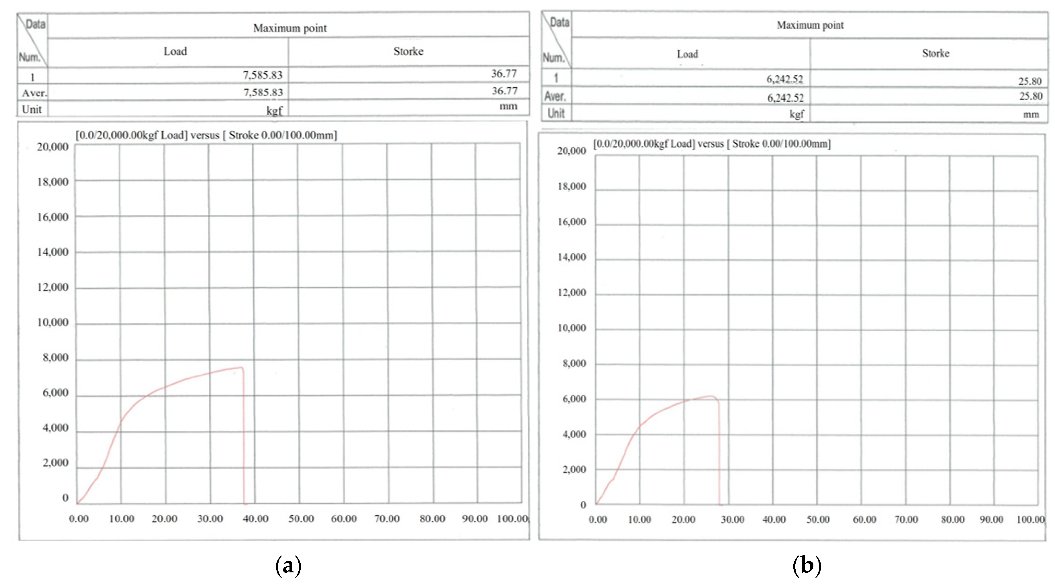
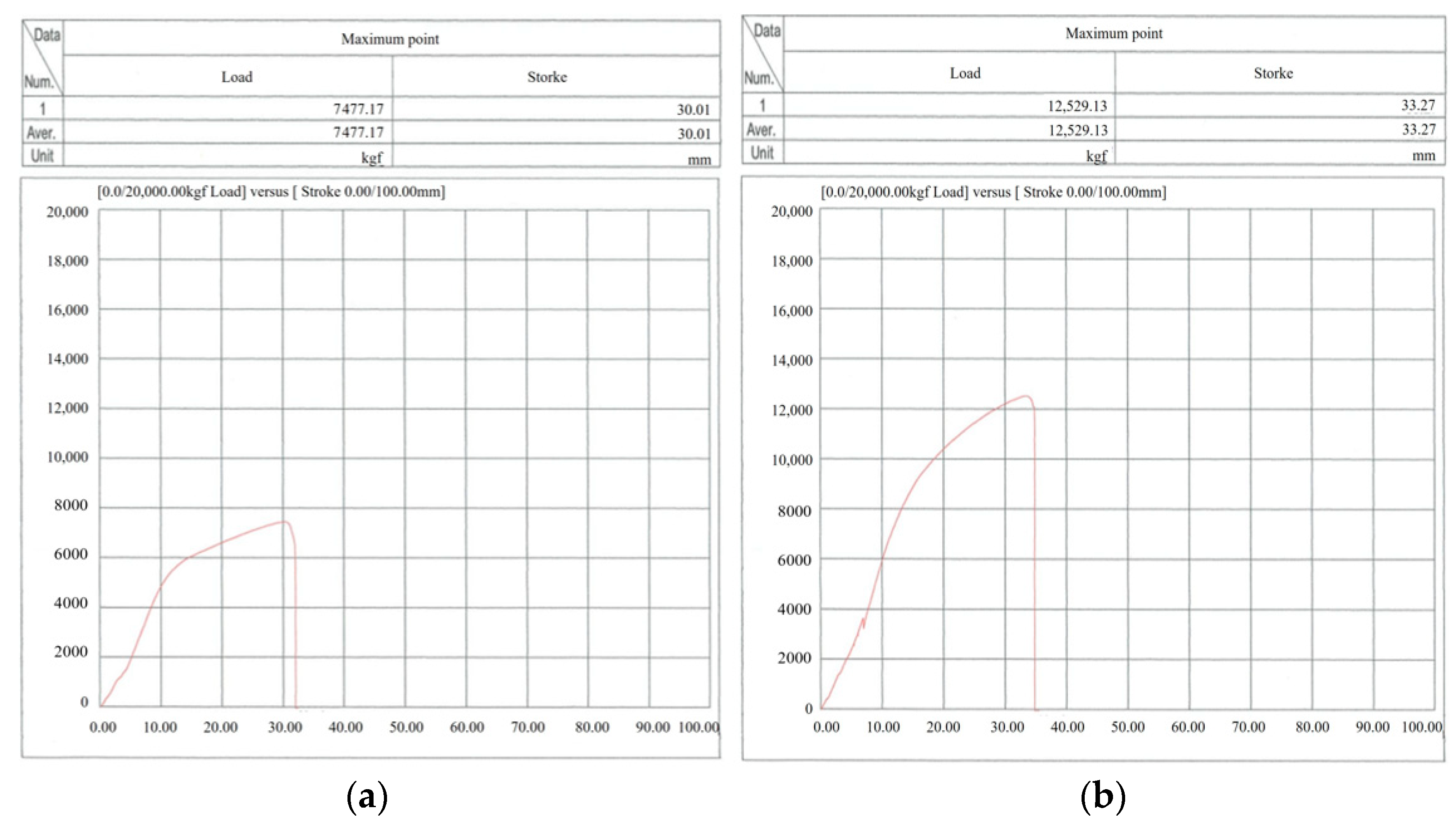
3.3. Experimental Evaluation of Chain Fracture

As summarized in Table 3, the supplier’s test certificate for the chain specifies a Safe Working Load (S.W.L) of 1600 kgf, a Proof Load of 3200 kgf, and a Breaking Load of 6400 kgf. Based on these values, the maximum Safety Factor is indicated as 4.
To verify whether the chain meets the specifications stated in the manufacturer’s certificate and to assess the extent of strength degradation in the failed chain sling, a Breaking Load Test was conducted
The breaking load tests were conducted on both the failed chain slings and new chain slings of the same specification, with two test repetitions performed for each case. The new chain slings were tested in two configurations: a single-leg lifting setup and a double-leg setup in which the chains were directly wrapped around and connected to the eye bolts. The test results are summarized in Table 4, and Figure 8, Figure 9 and Figure 10 present the respective test reports for Chain A, Chain B, and the new chain.
The results for Chain A showed that in the first test, the breaking load was measured at 7370 kgf, approximately 1.15 times higher than the reference breaking load of 6400 kgf. However, in the second test, the breaking load was only 3970 kgf, which is about 62% of the standard value, indicating a significant reduction in durability. For Chain B, the first test yielded a breaking load of 7585 kgf (1.18 times the standard), while the second test result was 6242 kgf, or approximately 97% of the standard breaking load. Although Chain B demonstrated higher breaking strength than Chain A, the fact that one result fell below the reference value suggests that deformation or aging may have already progressed.
In the single-leg test of the new chain, the breaking load was measured at 7477 kgf, which corresponds to 1.17 times the reference value. Theoretically, the double-leg configuration should yield a breaking load of approximately 14,954 kgf—twice that of the single-leg test. However, the actual measured value was 12,529 kgf, only 1.67 times higher. This reduction in strength is interpreted as a result of the chain being wrapped around eye bolts and hooks, which introduces not only tensile loads but also bending and torsional stresses. These additional stresses contribute to the degradation of the chain’s overall durability performance.
Meanwhile, at the accident site, a dual-leg sling configuration was applied to both Chain A and Chain B, resulting in a total of four legs supporting the load. Theoretically, given that the rated breaking load per single leg is 6400 kgf, the four-leg configuration should have been capable of withstanding a total breaking load of 25,600 kgf (6400 × 4). However, in practice, chain failure occurred under a load of only 5260 kgf. This discrepancy is believed to be due not only to the degradation of the chains’ durability caused by aging, but also to the uneven distribution of the load among the four chains.
During multi-leg slinging operations, variations in chain length or link size can lead to imbalanced load distribution, causing excessive stress to concentrate on a specific chain, potentially leading to failure. In practice, workers often match the number of chain links attached to the hook to ensure an even load distribution when using more than two legs. This is because differences in link size or chain length can significantly hinder proper load sharing, increasing the risk of overloading a particular chain.
Therefore, as discussed in Section 2, chain slings must be assembled using standard connection methods involving appropriate slinging components such as shackles and hooks. Strict adherence to these standards during lifting operations is essential to prevent chain damage and failure accidents.

3.4. Review of Safety Factor

The Safe Working Load (S.W.L) refers to the maximum allowable load that ensures safe lifting operations under the assumption of a static, straight-line loading condition. It is also commonly referred to as the working load or allowable load. If the load applied to the chain exceeds the S.W.L, permanent deformation, cracking, or damage may occur. Therefore, to ensure safe lifting operations, the applied load must always remain within the designated S.W.L. The safety factor is defined as the ratio of the breaking load to the maximum applied working load. As shown in Table 5, the Industrial Safety and Health Standards Regulations mandate a minimum safety factor of 5 for lifting accessories such as chains and wire ropes.
However, as noted in Section 3.3, the product certificate provided by the supplier specifies the S.W.L of the chain as 1600 kgf and the breaking load as 6400 kgf. This yields a theoretical safety factor of 4, which is approximately 20% lower than the legal requirement.
If the legally required safety factor of 5 were applied to this chain, the allowable S.W.L would be recalculated as 1280 kgf (6400 kgf ÷ 5). When using this chain in a four-leg sling configuration, the total lifting capacity would then be 5120 kgf (1280 kgf × 4 legs). In the incident under investigation, the actual weight of the lifted object was found to be 5260 kgf, which exceeds the calculated S.W.L by approximately 1.02 times.
Accordingly, it is concluded that the lifting operation in this case did not satisfy the minimum safety factor requirement and was carried out under improper and unsafe working conditions.

3.5. Evaluation of the Eye Bolt

Due to the unavailability of records regarding the purchase date and supplier of the eye bolt, its specifications were assessed based on the engraved marking “M30” and the indicated Safe Working Load (S.W.L) of 3600 kg. According to the current DIN 580 standard [35], as shown in Table 6, the Working Load Limit (W.L.L) for an M30 eye bolt is defined as 3200 kg. However, the eye bolt used at the accident site is presumed to have been manufactured under a previous revision of the DIN 580 standard, under which the S.W.L was designated as 3600 kg.
Given this context, the load of the lifted object in the incident—5260 kg—exceeded the marked S.W.L of 3600 kg by approximately 1.46 times. This indicates that the eye bolt was clearly unsuitable for the lifting operation conducted at the time.
As shown in Figure 11, the eye bolt exhibited signs of deformation and fracture. Considering that a lateral load approximately 1.46 times the S.W.L was applied to the eye bolt during lifting, it is presumed that structural deformation and damage to the ring portion had already initiated. Ultimately, the eye bolt is believed to have fractured due to the impact force generated during the drop of the heavy object.

3.6. Comprehensive Review of Chain Failure (Cause)

3.6.1. Use of Auxiliary Chains Without Load Marking and Below Standard Specifications

Chain slings used for lifting heavy objects must have the Safe Working Load (S.W.L) clearly marked at a location visible to the operator, and must be equipped with hooks, shackles, rings, or links at both ends. Only chain slings that meet these requirements are permitted for use as crane lifting accessories. However, in the case of this accident, the chain sling used had no S.W.L marking and was equipped with a hook on only one end, indicating that a non-compliant auxiliary chain sling was used during the lifting operation.

3.6.2. Use of Chains Without Considering Safety Factor Requirements

Chain slings for lifting operations must be selected with an adequate Safety Factor relative to the working load, in accordance with relevant regulations and technical standards. In this case, the chain slings were used without considering the appropriate safety factor, ultimately resulting in chain fracture when the actual load of the lifted object exceeded the chain’s capacity.

3.6.3. Use of Chains with Degraded Durability

For chain slings, if the diameter of the link section has decreased by more than 10% from its original specification, or if the total chain length has increased by more than 5%, the chain must be discarded immediately. However, in this case, the chain was used without any prior inspection for wear or deformation, leading to structural vulnerability due to aging and deterioration.

3.6.4. Use of Eye Bolt Exceeding Its Rated Lifting Capacity

The eye bolt used in the incident was rated with an S.W.L of 3600 kg, but the actual load lifted was 5260 kg, which exceeds the rated capacity by approximately 1.46 times.
This resulted in deformation of the eye bolt, and it is presumed that the final fracture occurred due to the impact force generated by the falling heavy object following the chain failure.

4. Structural Analysis

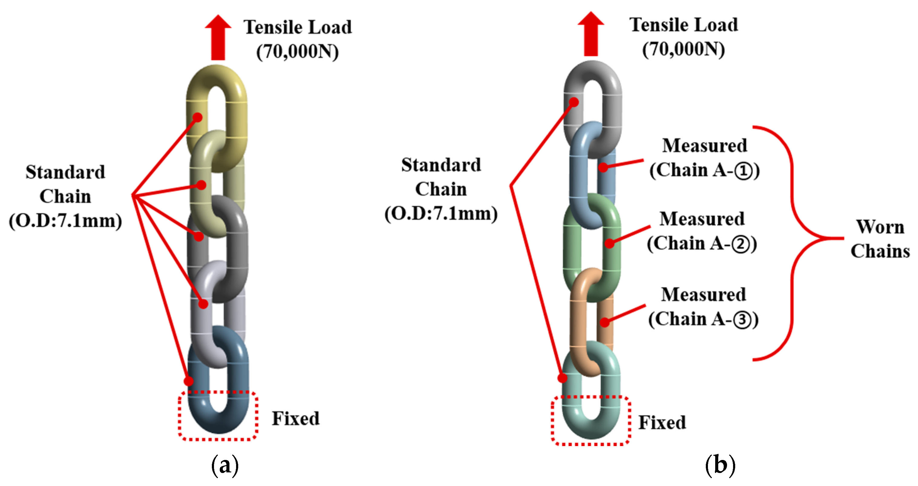
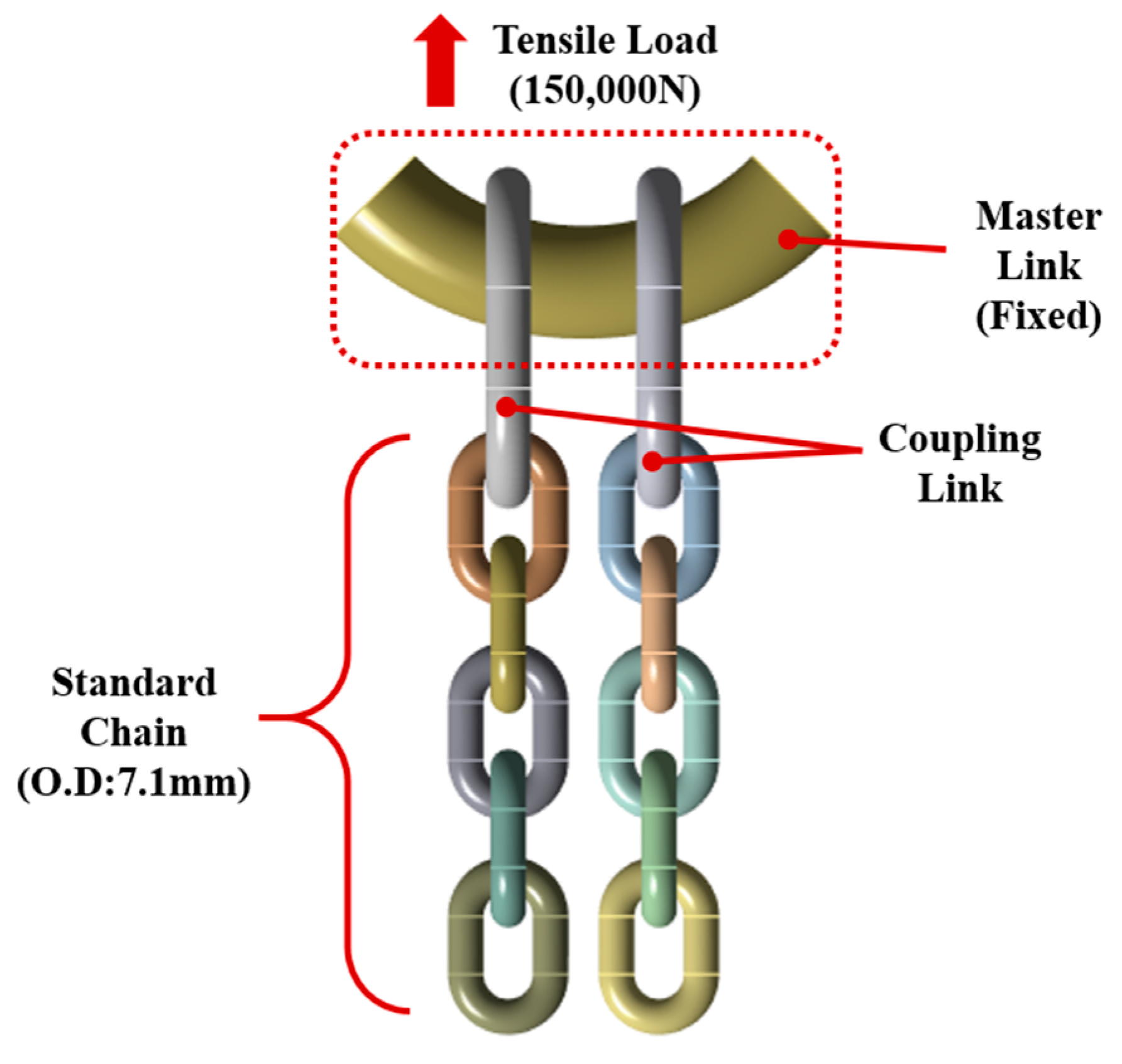
4.1. Analysis Model and Boundary Conditions

In this study, a structural analysis was conducted to compare and evaluate the stress distribution and failure behavior under two different loading scenarios: (1) axial tensile loading in a single-leg sling configuration, and (2) combined loading due to bending when the chain sling is directly connected to an eye bolt. The analysis focused on both a standardized chain and an aged, field-failed chain (Chain A). According to the KS B 2818 standard (see Table 1), a nominal chain with a diameter of 7.1 mm was modeled as the reference, while the damaged chain (Chain A) used in the actual accident (see Table 2) was also modeled. A total of five cases were configured for simulation.
Cases 1 and 2 represent single-leg sling configurations. Case 1 consists entirely of standardized chain elements, whereas Case 2 incorporates both standardized chains and the field-measured geometry of Chain A. This was done to investigate how differences in chain length or reduced diameter affect failure characteristics depending on the assembly conditions. For both cases, only five chain links were modeled to improve computational efficiency.
Cases 3 through 5 represent double-leg sling configurations, all based on standardized chain elements. Among these, Case 3 models a standard connection using a master link, while Cases 4 and 5 simulate non-standard configurations in which the chain sling is looped directly around an M30 eye bolt. To analyze the influence of the chain’s contact orientation with the eye bolt on stress distribution and failure patterns, Case 4 assumes that both legs of the chain share the load simultaneously, while Case 5 assumes that only one leg bears the load. For simplification, the analysis domain in Cases 4 and 5 was limited to the contact region between the chain and the eye bolt, consisting of nine chain links.
For all cases, the boundary conditions were defined by fixing one end of the chain sling while applying a gradually increasing tensile load to the opposite end. The maximum tensile loads applied were 70,000 N for Cases 1 and 2, and 150,000 N for Cases 3 through 5. The analysis evaluated the variations in stress and deformation as the load increased, as well as the maximum elongation length immediately prior to failure. Detailed analysis parameters are summarized in Table 7 and illustrated in Figure 12, Figure 13 and Figure 14.
In this analysis, a coefficient of friction of 0.3 was applied to define the contact conditions. This value represents a moderate level of resistance to sliding and was selected to ensure numerical stability and convergence during the simulation. Although the coefficient of friction between steel surfaces in dry conditions is typically around 0.4, the value was conservatively limited to 0.3 in order to avoid excessive computation time and divergence issues commonly encountered in nonlinear contact analysis.
Unlike bonded contact, where the state of contact pairs remains fixed throughout the analysis, frictional contact exhibits true nonlinear behavior due to its sensitivity to displacement-dependent stiffness changes. This allows for a more realistic simulation of physical phenomena such as sliding, sticking, and separation between contact surfaces.
In addition, all chains were modeled as flexible bodies rather than rigid bodies. This modeling approach enables a more accurate representation of structural responses, allowing for local deformation, global displacement, contact reaction forces, and material nonlinearity under external loads and contact interactions. The use of flexible body modeling is particularly suitable for simulating the actual behavior of chains under increasing load conditions, including continuous deformation, inter-chain sliding, stress concentration at contact points, and eventual fracture. Therefore, incorporating flexible body definitions along with nonlinear material models and contact conditions is essential for evaluating potential failure in chain systems.
However, because the material properties of the actual failed chain were not precisely identified, the absolute comparison of numerical results has inherent limitations. Therefore, this study focuses on the relative trends observed across the different connection configurations and elongation patterns from Cases 1 to 5.
Finite element analysis (FEA) was conducted using the commercial software Ansys Workbench 2024R2. Ansys Workbench is an integrated platform that combines pre-processing, solving, and post-processing in a user-friendly graphical interface, enabling efficient modeling of complex geometries and the application of diverse loading conditions.
In addition to linear static analysis, it provides high accuracy and stability in nonlinear structural analyses, such as large deformation, material nonlinearity, and contact problems. Moreover, it includes a wide range of built-in material models, allowing for simulations that closely approximate real-world behavior, including elasticity, plasticity, viscoelasticity, and failure. Its automated meshing tools and mesh quality control features contribute to improved reliability and consistency of the results.
In this study, the advantages of Ansys Workbench were fully utilized to perform a systematic and quantitative structural behavior analysis without physical experiments. The stress distribution and deformation of the structure were precisely evaluated under complex boundary and loading conditions.

4.2. Analysis Model

The exact material specifications of the chain used in this study were not clearly documented in the test certificates provided by the supplier. Therefore, AISI 4340 steel was selected as the representative material for the analysis, as it exhibits mechanical properties similar to those of Grade 100 alloy steel, which is commonly used for chain slings.
It is noteworthy that AISI 4340 is known for its sensitivity to heat treatment conditions, which can significantly affect its mechanical properties such as yield strength and ultimate tensile strength. Given this variability, the material properties used in the present analysis were based on the mechanical characteristics of AISI 4340 under a normalizing heat treatment condition. The fundamental material properties adopted in the analysis, including Young’s modulus, Poisson’s ratio, and density, are summarized in Table 8.
Meanwhile, to more accurately simulate the ductile deformation and eventual fracture behavior of the material under the loading conditions applied to the chain, the Johnson–Cook strength model was adopted in this analysis. This model is widely used in the analysis of various industrial materials, as it effectively represents the nonlinear stress–strain relationship and fracture characteristics exhibited by ductile metallic materials under practical conditions.
The Johnson–Cook strength model is defined as shown in Equation (1), where the flow stress (σ) is determined by parameters such as the initial yield strength (A), strain hardening coefficient (B), strain rate sensitivity coefficient (C), strain hardening exponent (n), equivalent plastic strain ( ε ) and thermal softening exponent (m). In this study, the plastic strain rate ( ε ˙ 0 ) was set to 1 (/sec), and the influence of the reference plastic strain rate ( ε ˙ 0 ), reference temperature ( T 0 ), and melting temperature ( T m ) was neglected. As a result, the equation can be simplified as shown in Equation (2).
σ = ( A + B ε n ) 1 + C ln ε ˙ ε 0 ˙ 1 T T 0 T m T 0 m
σ = ( A + B ε n ) ( 1 + C ln ε ˙ )
Fracture damage modeling was performed based on the cumulative damage law of the Johnson–Cook fracture model, as expressed in Equation (3). This model is designed to predict the onset of fracture by quantitatively evaluating the accumulation of plastic strain in the material under applied external loads. Fracture is assumed to occur when the equivalent plastic strain accumulates beyond a certain threshold, and this is expressed by the relationship between the equivalent plastic strain increment ( Δ ε ¯ ) and the plastic strain at failure ( ε ¯ f ), where cumulative damage (D) reaches or exceeds a value of 1, as shown in Equation (4).
The plastic strain at failure ( ε ¯ f ) is determined by variables such as the strain rate ratio ( ε ˙ / ε ˙ 0 ), the ratio of hydrostatic pressure to equivalent stress ( P / σ ¯ ), and a set of damage constants (D1 through D5), as well as the reference temperature ( T 0 ) and melting temperature ( T m ). If the effect of temperature is neglected, the model can be simplified as shown in Equation (5).
The material constants used in the Johnson–Cook model and the parameters related to fracture are summarized in Table 9 and Table 10. Among them, the damage constants (D1 through D5), which are used to determine the fracture conditions, are derived from experimental data and represent the quantified fracture characteristics of the specific material.
D = Δ ε ¯ ε ¯ f
ε ¯ f = D 1 + D 2 e D 3 P σ ¯ 1 + D 4 ln ε ˙ ε 0 ˙ 1 + D 5 T T 0 T m T 0
ε ¯ f = D 1 + D 2 e D 3 P σ ¯ 1 + D 4 ln ε ˙ ε 0 ˙
Figure 15, Figure 16 and Figure 17 present the finite element meshing results of the analysis models used in this study. Considering the geometry of the chain products, the models were discretized using tetrahedral elements. The element size was set to 1 mm for the main body of the chain, 0.8 mm for the contact areas between chain links, and 2–3 mm for the connecting links, master links, and eyebolts, which were not the primary focus of the analysis.

4.3. Analysis Results

The analysis results of Case 1 are presented in Figure 18. When the tensile elongation reaches 50.042 mm, the maximum stress is 1150.5 MPa, and fracture occurs. The corresponding maximum tensile load (or fracture load) is 62,300 N. Although this shows a relatively large error of approximately 17.73% compared to the actual fracture load of the product (73,351 N), the deviation is only 0.77% when compared with the fracture load value of 62,784 N specified in the material certificate, indicating a very close correlation. However, as noted in Section 4.1, the material properties of the chain used in the actual test could not be precisely identified. Therefore, rather than comparing absolute values with the actual product, this study focuses on comparing the relative behavior across the different cases.
The analysis results of Case 2 are shown in Figure 19. When the tensile elongation reaches 25.453 mm, the maximum stress is 1125 MPa, and fracture occurs. The maximum tensile load at this point is 46,800 N. Compared to the standard product in Case 1, the aged chain failed at approximately 75.12% of the tensile load capacity of the new product. This can be attributed to the reduction in effective cross-sectional area caused by a decrease in chain diameter and an increase in pitch, which significantly intensified the tensile stress and thereby led to earlier yielding and fracture behavior.
In other words, the reduction in the chain’s diameter caused stress concentration under loading, which—as described by the Johnson–Cook model—results in rapid accumulation of plastic strain, leading to premature fracture. As expected, the initial fracture occurred in the A-③ section of Chain A, where the diameter reduction and pitch increase were the most severe.
The analysis results of Case 3 are presented in Figure 20. In this case, a standard connection method was applied, in which an intermediate link (coupling link) and a master link were used together in the chain sling configuration. This is the most commonly used connection method in industrial settings and is designed to ensure that the load is evenly distributed throughout the entire chain sling. It is characterized by high reliability in actual lifting and securing operations, while minimizing the occurrence of abnormal stresses such as chain twisting or bending.
According to the analysis, when the tensile elongation reached 50.037 mm, the maximum stress in the chain rose to approximately 1156.1 MPa, at which point fracture occurred in the entire chain sling system. The maximum tensile load applied at the moment of failure was approximately 124,500 N, which aligns with the theoretical expectation that a two-leg configuration can support nearly twice the load of a single-leg configuration. In fact, in Case 1, where a single chain of the same specification was used, the fracture load was approximately 62,800 N, and the failure in Case 3 occurred at about 1.98 times that load.
The structural advantages of the connection method using intermediate and master links can be summarized as follows:
First, the chain’s connecting parts form a symmetrical structure, and the load is evenly distributed in the vertical direction relative to the tensile axis, preventing stress concentration from occurring locally on the chain.
Second, the indirect connection through the master link reduces friction and torsional stress between the chains, thereby restricting free deformation of the chains and increasing the overall stiffness of the system.
Third, this type of connection is recommended by international standards such as ISO 16872 and EN 818-4 [36,37], and is also suggested in industrial safety guidelines as a connection method that minimizes deformation and fatigue accumulation due to repeated use.
The analysis results of Case 4 are shown in Figure 21. In this case, a non-standard connection method was applied in which the chain sling was directly wrapped around an M30 eyebolt, and the mechanical behavior of the chain under tensile loading was quantitatively evaluated.
Initially, Chain ① is in contact with the eye bolt and supports the applied load. As the load gradually increases, excessive force causes deformation in Chain ①, and relative sliding between the chains leads Chains ② and ③ to come into contact with the eye bolt as well.
When the load exceeds approximately 780,000 N, all three chains (Chains ① to ③) begin to share the load, and bending deformation also occurs in Chains ② and ③.
However, since Chain ① has been supporting the load from the beginning, it accumulates significant stress and deformation over time, ultimately leading to its failure before the others.
According to the analysis, when the tensile elongation reached approximately 41.505 mm, the maximum stress in the chain rose to about 1178.9 MPa, immediately followed by fracture. The maximum tensile load applied at that moment was measured to be 106,500 N.
This value is approximately 85.54% of the maximum tensile load observed in Case 3 (124,500 N), where the standard connection method was used. This result indicates that even with chains of the same specification, the mechanical strength can vary significantly depending on the connection method. In the non-standard method, the chain is directly wrapped around the eyebolt, causing the chain links to experience not only tensile force but also additional bending and compressive loads. Especially when the chain is wrapped over the curved surface of the eyebolt, the curvature of the chain is constrained, and at the contact region, radial compressive stress and localized bending stress are induced. This leads to much higher stress concentration than in a case of pure tensile loading and acts as a major factor promoting structural damage and fatigue crack initiation.
Such a nonlinear stress distribution, as also explained by the Johnson–Cook cumulative damage model, creates conditions where plastic strain rapidly accumulates in specific regions of the chain, making crack initiation more likely. In the present analysis, abnormal stress concentration occurred near the chain’s contact area, and accordingly, the fracture also took place in that vicinity. This implies that the non-standard connection method alters the intended load transfer path of the chain, thereby reducing the overall structural stability.
The analysis results of Case 5 are presented in Figure 22. This case also applied a non-standard connection method, in which the chain was directly wrapped around an eyebolt. However, unlike Case 4, both legs of the chain were configured to support the load symmetrically after being wrapped around the eyebolt. This setup was intended to simulate a scenario commonly observed in the field, where chains are wrapped in a symmetrical fashion, and to analyze the influence of contact direction on the structural response.
In Case 5, Chains ② and ③ are in direct contact with the eye bolt. Unlike Case 4, however, there is no change in the contact location as the load increases. This means that Chains ② and ③ carry the entire load until failure occurs.
Chains ② and ③ are subjected to direct tensile loading, while also experiencing bending deformation due to contact with the eye bolt. In contrast, Chain ① is not part of the direct load path, but tensile and bending deformation are induced indirectly as a result of the tensile forces acting through Chains ② and ③.
According to the analysis, when the tensile elongation reached 32.007 mm, the maximum stress in the chain rose to approximately 1213.3 MPa, and fracture occurred immediately thereafter. The corresponding maximum tensile load was 105,000 N, which is approximately 84.34% of the value observed in Case 3 (124,500 N). This result is very similar to that of Case 4, indicating that in non-standard connection methods, localized stress concentration caused by the manner of attachment has a greater impact on the durability of the chain than factors such as the wrapping direction or the number of load-bearing legs.
These findings are also supported by existing literature. For example, international standards such as DIN EN 818-4 and ISO 3056 [37,38] strongly recommend using auxiliary components such as master links or shackles when assembling chain slings. They explicitly state that the direct wrapping method cannot ensure mechanical reliability. The present analysis results provide structural analysis-based evidence that supports the technical rationale behind these standards.
Additionally, this study confirmed that the nonlinearity of the analysis model increases depending on the chain’s contact conditions and load distribution, indicating that the failure mechanism of the chain cannot be predicted by tensile behavior alone. Factors such as the contact angle, curvature radius, and coefficient of friction were found to significantly influence the failure point. These findings suggest the need for more detailed parametric analyses in future research.
Table 11 summarizes the analysis results from Case 1 to Case 5. In summary, Case 3 effectively demonstrates the structural stability and tensile resistance characteristics of a standard connection method. This is particularly contrasted with the results from Case 4 and Case 5, which represent non-standard connection methods. The use of non-standard methods was shown to reduce the failure load of the chain sling system by more than 15%, primarily due to altered load transfer paths and stress concentration mechanisms. Consequently, directly attaching the chain to an eyebolt changes the designed load path, induces nonlinear stress distributions and bending deformations, and significantly compromises chain durability. This aligns with the Johnson-Cook damage model, which indicates that damage accumulation progresses more rapidly under bending behavior than under tensile behavior.
Even for chains of identical material and specifications, the connection method can cause considerable variation in load distribution characteristics and fracture behavior. This highlights the importance of connection methods in the selection and use of chain slings in industrial applications.
Therefore, even new chains must be connected properly by strictly adhering to technical guidelines for use and inspection of chain slings. Regular inspections and timely disposal are essential to prevent accidents. Although direct wrapping of chains around eyebolts still occurs in practice, this study is meaningful in that it quantitatively evaluates the negative impact of such practices on chain durability.
For reference, Figure 23, Figure 24 and Figure 25 provide detailed illustrations of the fracture characteristics of the chain in each respective case.

5. Guidelines for On-Site Implementation

Based on the findings of this study, guidelines for the management and safe usage of chain slings in industrial field applications are proposed. Prior to using a chain sling, it is essential to perform direct dimensional inspections of key parameters such as the nominal diameter (d) and pitch (p). Deformed chains—specifically, those with more than a 10% reduction in diameter or more than a 5% increase in pitch—must be identified and discarded.
In accordance with international standards such as ISO 16872 and EN 818-4, chain slings must be assembled using appropriate rigging accessories such as shackles and master links. The practice of directly wrapping the chain around eyebolts or similar structures should be strictly prohibited. Furthermore, attention must be paid to the direction of chain contact and the state of load distribution to prevent the occurrence of unnecessary bending loads or torsional stresses on the chain.
Regular maintenance and the establishment of replacement intervals are also crucial. Chain slings must be subjected to periodic detailed inspections depending on the frequency of use, working environment, and loading conditions, and should be replaced as necessary under a structured management system. If any external abnormalities—such as cracks, deformation, or corrosion—are detected, the sling must be taken out of service immediately, and further inspection should be carried out.
In addition, regular safety training must be provided to workers regarding proper usage, inspection methods, and appropriate measures to take when defects are discovered. Pre-use inspections, including an assessment of the condition of the chain sling, must be conducted before each operation to prevent potential accidents.

6. Conclusions

This study investigated the root causes of chain failure accidents and established technical measures for prevention by reviewing relevant regulations and technical standards, conducting visual and dimensional inspections, performing actual fracture tests, and carrying out structural analyses. In particular, the mechanical behavior differences between standard fastening methods (using intermediate and master links) and non-standard fastening methods (directly wrapping around eyebolts) were quantitatively analyzed. Five structural analysis cases were established, and for each case, the maximum tensile load and stress distribution were compared.
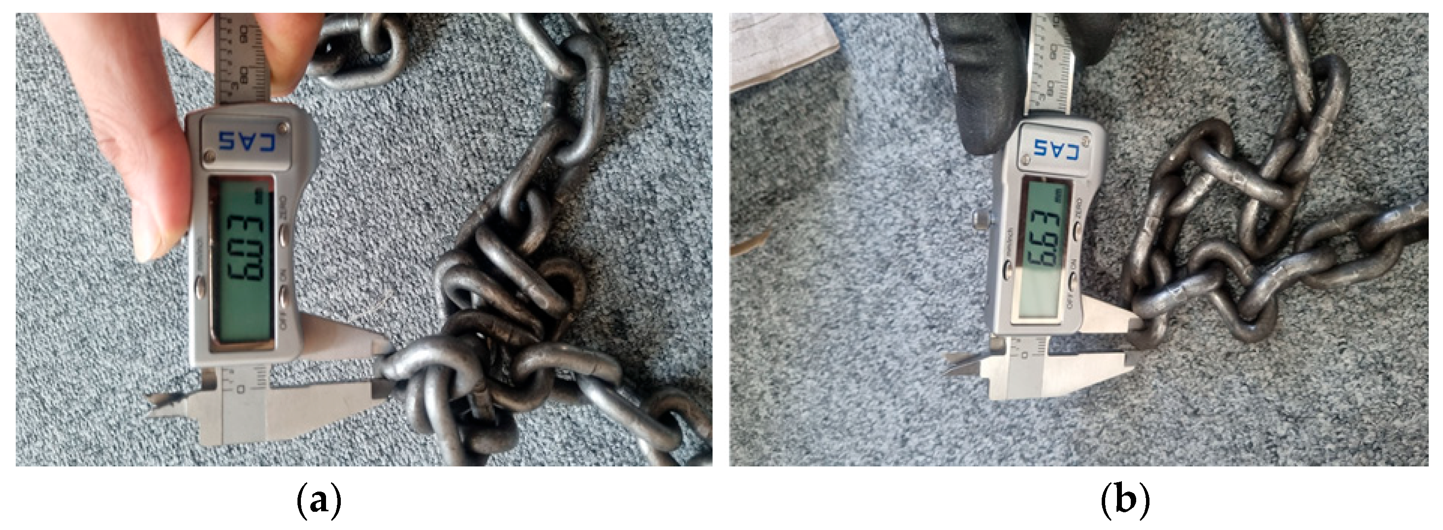
  • Dimensional measurements of the chain slings revealed that in some cases, the wire diameter had decreased by more than 10%, or the pitch had increased by more than 5%, compared to standard values. In particular, the diameter of Chain A-③ had decreased by approximately 15% to 6.03 mm compared to the standard 7.1 mm, exceeding the discard criteria. This indicates that plastic deformation and elongation occurred during repeated use, highlighting the necessity of dimensional inspections and immediate disposal of non-compliant products before use.
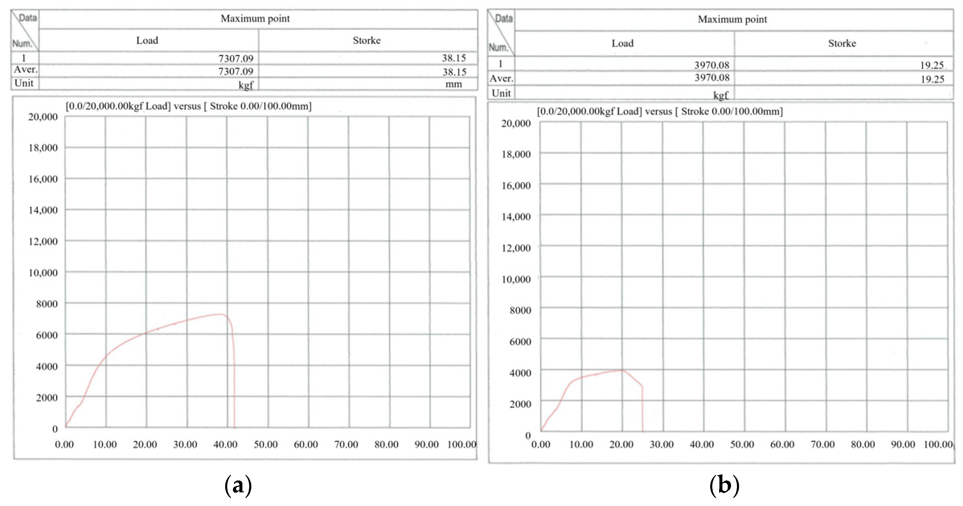
  • The fracture test results showed that the aged Chain A failed at 3970 kgf during the second test—only about 62% of the standard fracture load of 6400 kgf. Chain B also failed at 6242 kgf, falling below the standard. These results demonstrate that external and dimensional degradation directly leads to reduced strength, emphasizing the importance of strictly enforcing discard criteria.
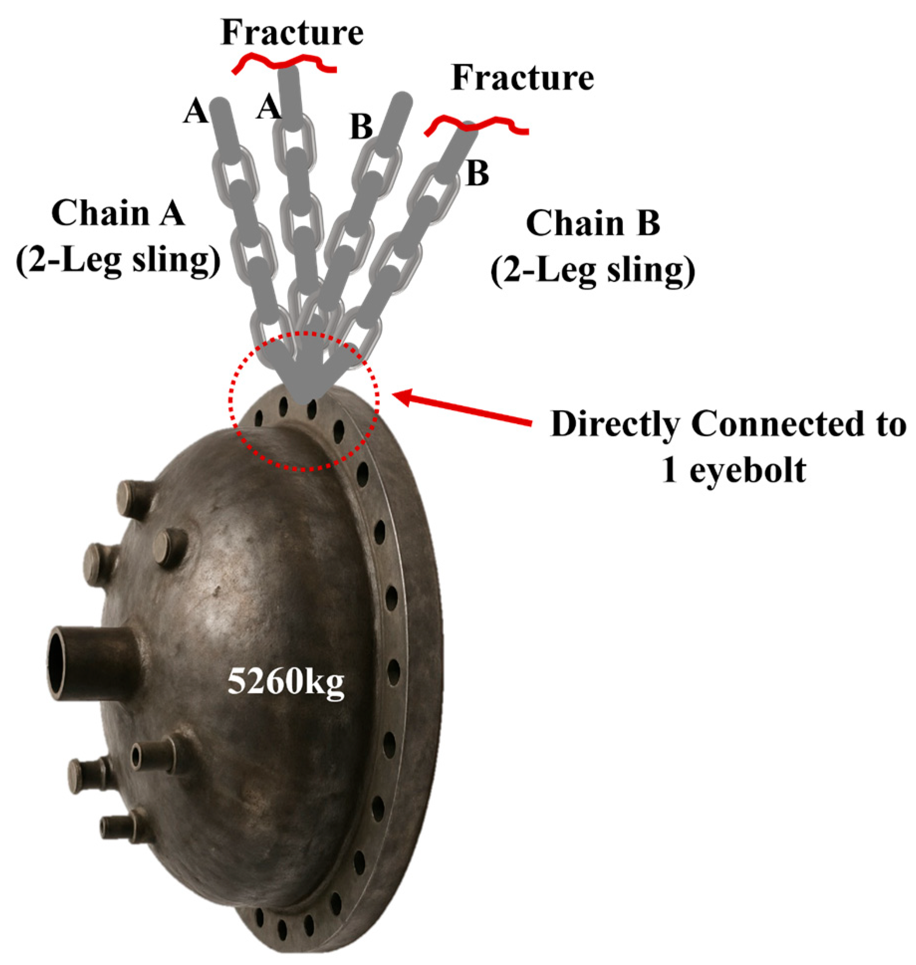
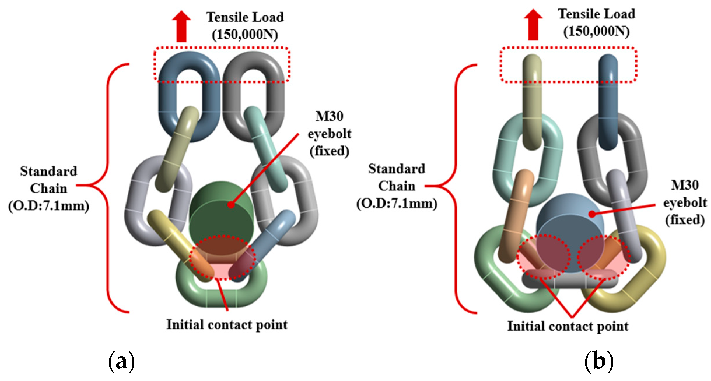
  • Clear differences emerged based on the fastening method. When the new chain was used in a single-leg configuration, the fracture load was 7477 kgf. In contrast, when configured as a two-leg sling using a non-standard method, the fracture load was 12,529 kgf—only 83.8% of the theoretical value of 14,954 kgf. This reduction is attributed to the combined bending and torsional loads applied to the chain wrapped around the eyebolt. Notably, in the four-leg sling configuration (theoretically 25,600 kgf), failure occurred at just 5260 kgf, indicating a severe reduction in strength.
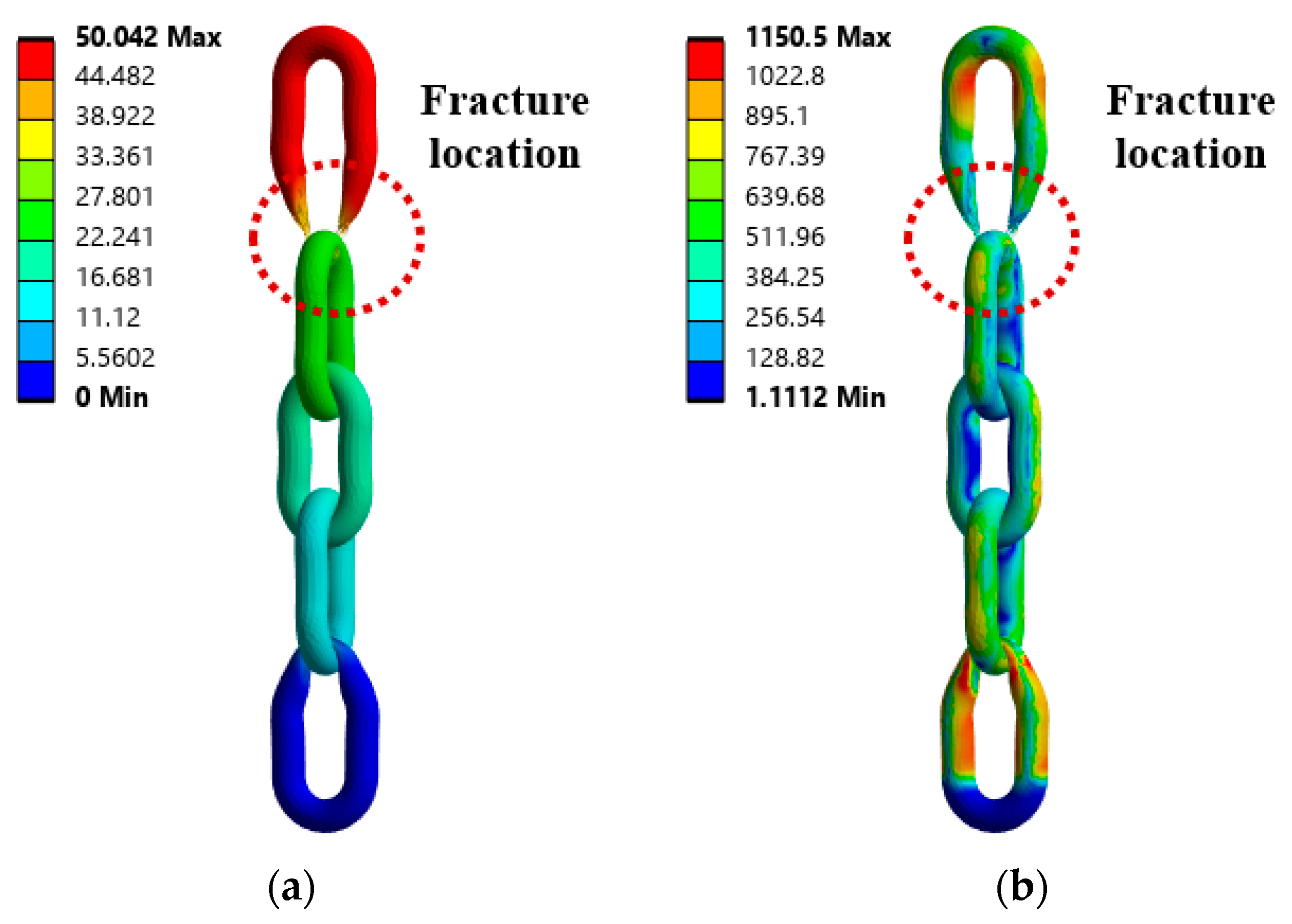
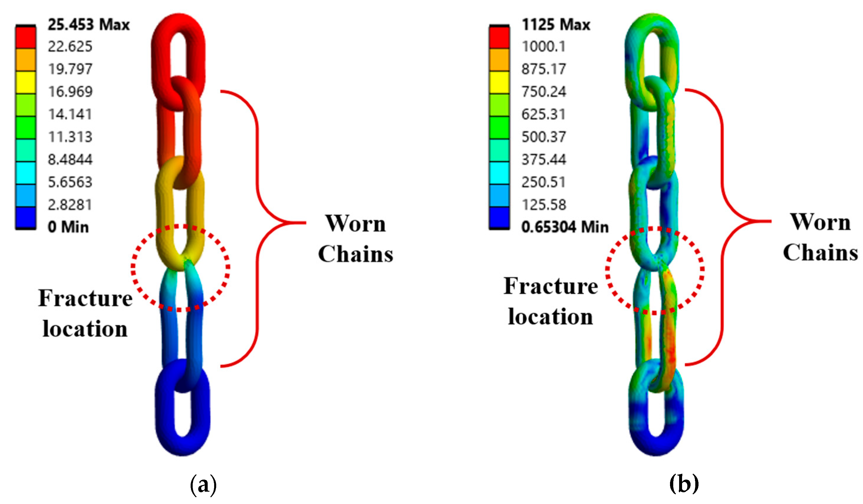
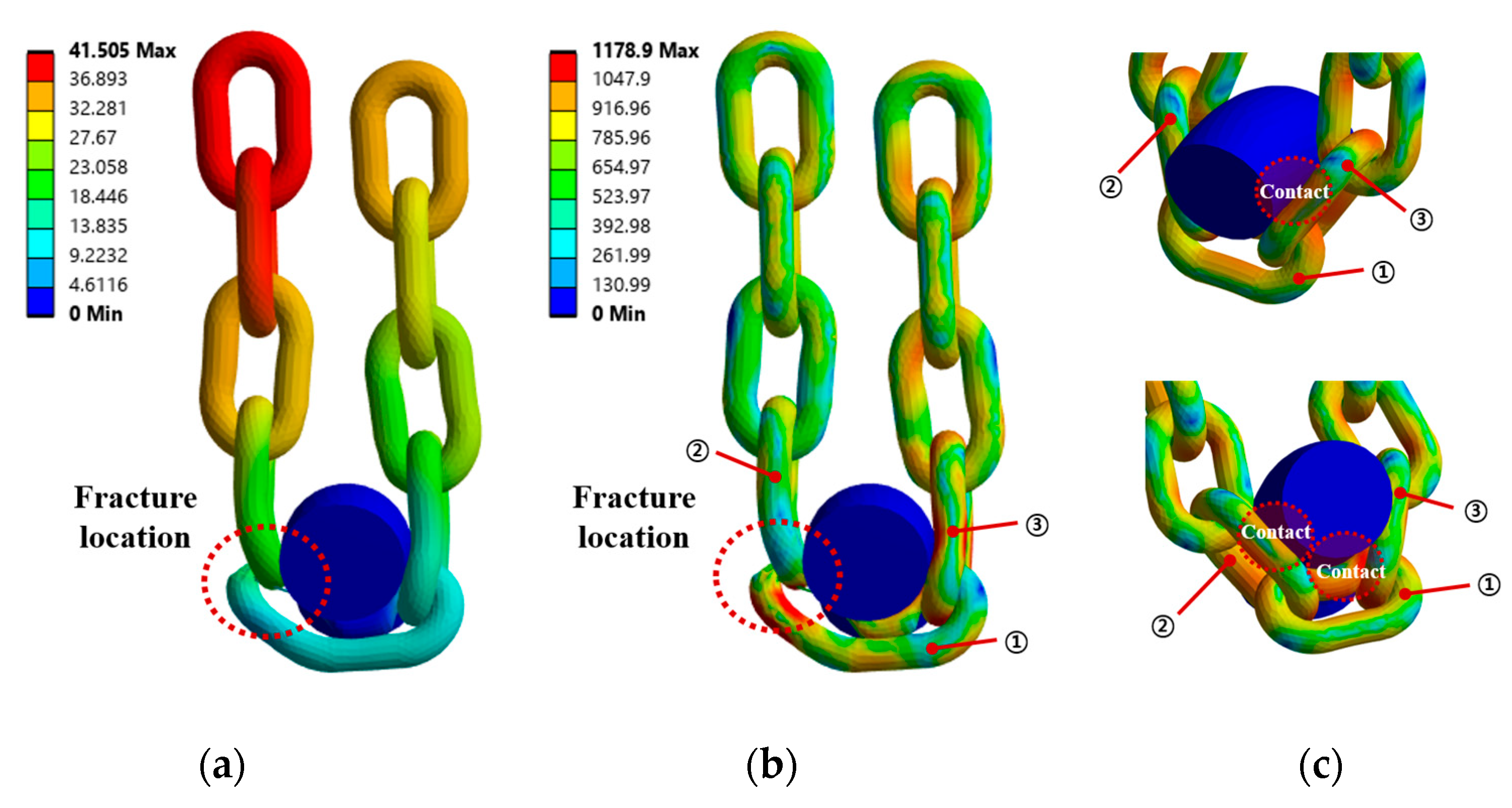
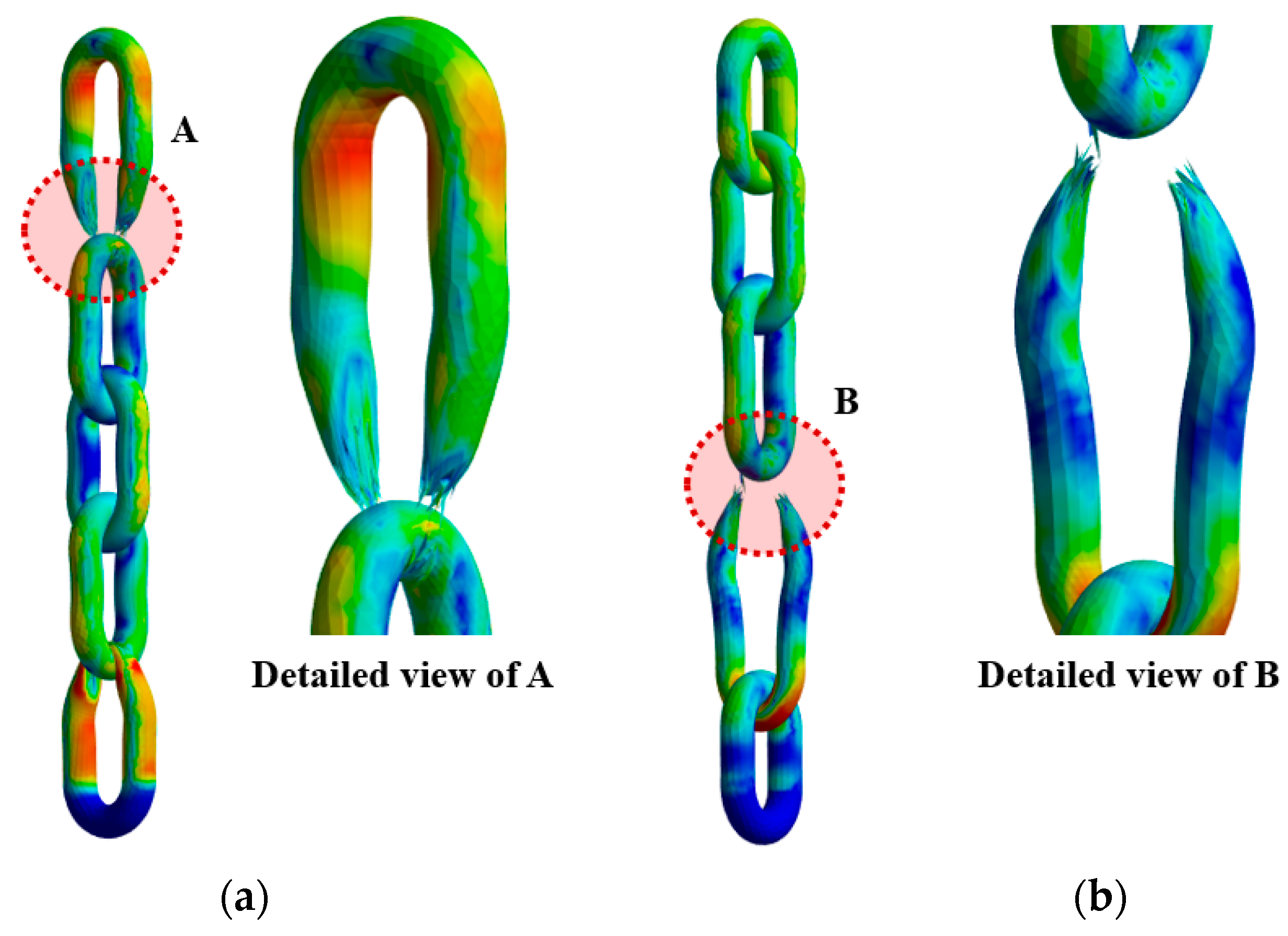
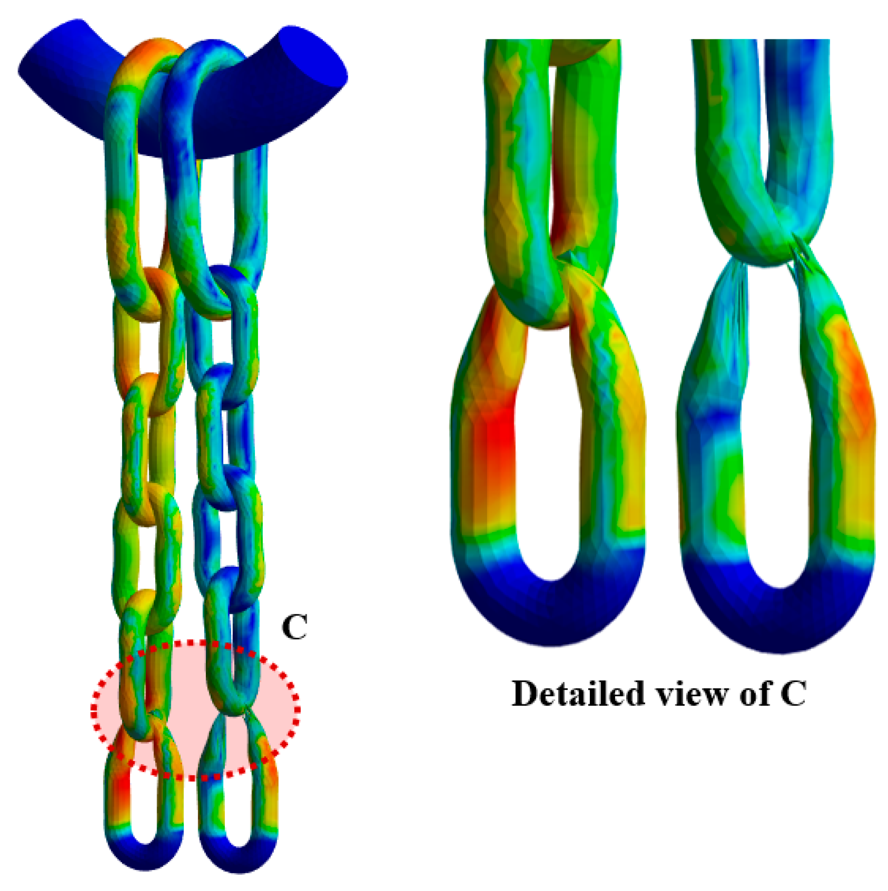
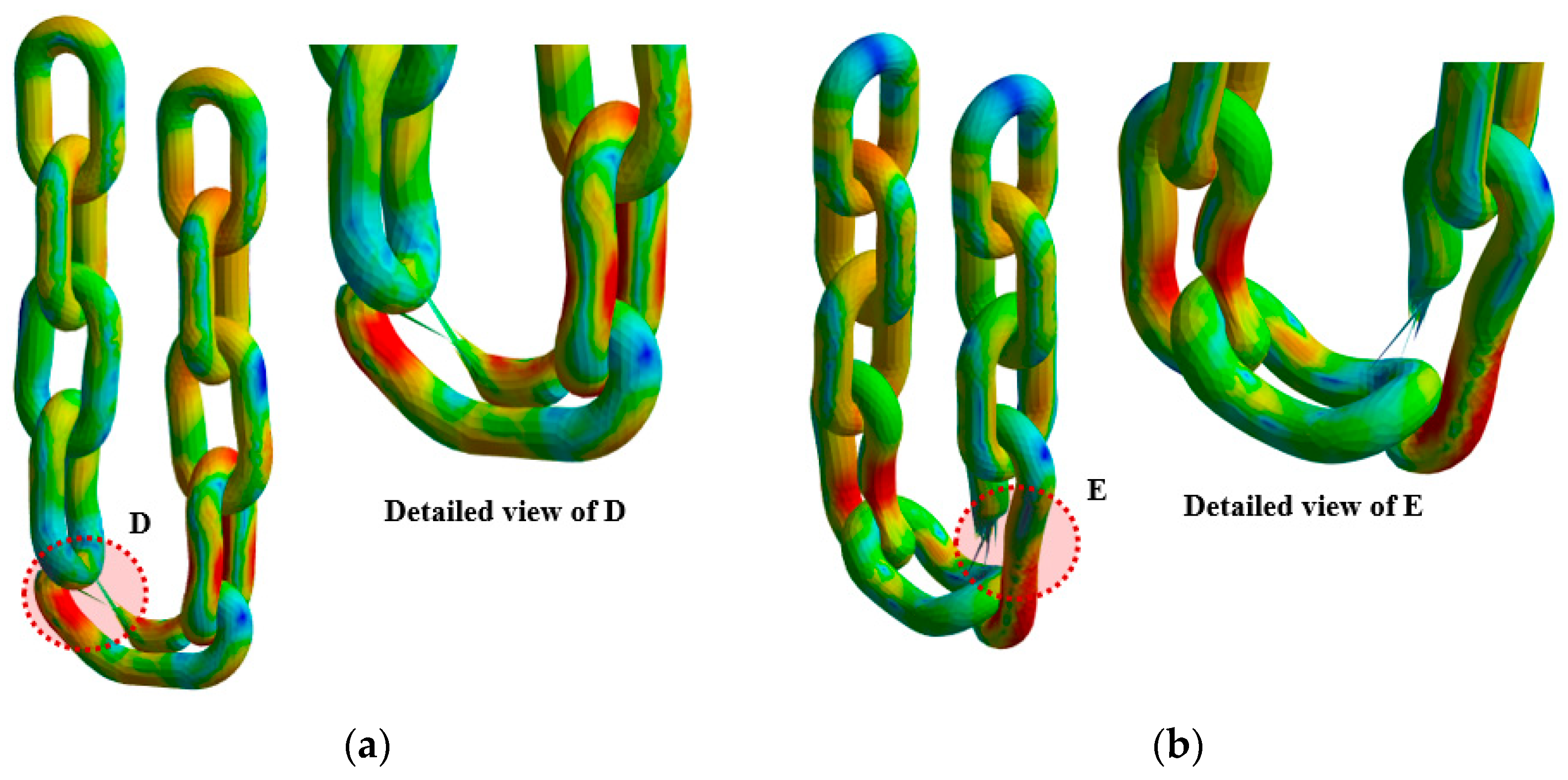
  • Structural analysis showed that Case 3 (standard fastening) allowed the load to be evenly distributed throughout the chain, with a maximum stress of approximately 1156 MPa and a maximum tensile load of about 124,500 N. This aligns with the chain’s design strength, and fracture occurred in a region with appropriate stress distribution rather than at the joints. In contrast, in Cases 4 and 5 (non-standard fastening), the chain was directly wrapped around the eyebolt, resulting in combined bending and compressive loads. The maximum stresses reached approximately 1179 MPa and 1213 MPa, while the maximum tensile loads were reduced to 106,500 N and 105,000 N, respectively—more than a 15% decrease. The failure points were located near the eyebolt contact area, clearly indicating nonlinear stress concentration and structural weakness.
  • This performance degradation was caused by the complex loading conditions—local bending, compressive stress, and contact friction—arising from wrapping the chain around the curved surface of the eyebolt. These conditions are consistent with the local plastic deformation and stress concentration predicted by the Johnson–Cook damage accumulation model. In particular, the non-standard fastening method distorts the chain’s intended load path, significantly reducing structural strength and increasing the likelihood of unexpected failures.
  • This study structurally validated the fastening methods prescribed by international standards such as DIN EN 818-4 and ISO 3056 (using shackles or master links), and quantitatively analyzed the impact of non-standard fastening methods on chain strength and service life, making it a meaningful practical case.
  • The findings provide the following practical implications:
    • Standard fastening methods (using auxiliary connectors) must always be followed.
    • Wrapping chains directly around eyebolts should be strictly prohibited due to high local stress concentrations and structural damage risks.
    • Fatigue life and fracture behavior vary significantly depending on the fastening method; thus, these factors must be considered in both design and field application.
    • Subtle differences in chain curvature, contact angle, and friction conditions affect overall durability, necessitating regular inspections and clear discard criteria.
  • Future research should focus on fatigue analysis and the development of damage-accumulation-based life prediction models that incorporate additional parameters not considered in this study, such as cyclic loads, impact loads, and asymmetric loading. Further investigations are also needed into optimizing contact surface geometry, improving friction conditions, and designing auxiliary fastening components.

Author Contributions

Conceptualization, J.L.; methodology, Y.C.; validation, Y.C. and J.L.; investigation, Y.C.; resources, Y.C.; writing—original draft preparation, Y.C.; writing—review and editing, J.L.; supervision, J.L.; project administration, J.L. All authors have read and agreed to the published version of the manuscript.

Funding

This research was supported by the Basic Science Research Program through the National Research Foundation of Korea (NRF), funded by the Ministry of Education (2022R1I1A3069291) and “Regional Innovation System & Education (RISE)” Project, supported by the Ministry of Education and Gyeonsangnam-do (RISE Center).

Institutional Review Board Statement

Not applicable.

Informed Consent Statement

Not applicable.

Data Availability Statement

The original contributions presented in this study are included in the article. Further inquiries can be directed to the corresponding author.

Conflicts of Interest

The authors declare no conflicts of interest.

References

  1. Solazzi, L.; Danzi, N.; Gelfi, M.; Zavanella, L.E. Failure Analysis of a Pair of Failed Chain Links. Eng. Fail. Anal. 2023, 152, 107481. [Google Scholar] [CrossRef]
  2. U.S. Occupational Safety and Health Administration (OSHA). Sling Safety—Safe Sling Use. 2021. Available online: https://www.osha.gov/safe-sling-use (accessed on 4 April 2025).
  3. Japanese Industrial Safety and Health Association (JISHA). Slinging Work—Safety Guidelines for Sling Use. 2019. Available online: https://www.jisha.or.jp/international/jicosh/english/topics/slinging/slinging.html (accessed on 7 April 2025).
  4. Peerless Chain. Available online: https://peerlesschain.com/news/the-anatomy-of-an-alloy-chain-sling-failure (accessed on 3 April 2025).
  5. Steel Image Inc. Available online: https://steelimage.com/wp-content/uploads/2019/02/Fatigue-Failure-of-Automotive-Assmebly-Plant-Chain.pdf (accessed on 2 May 2025).
  6. Zarandi, E.P.; Skallerud, B.H. Experimental and Numerical Study of Mooring Chain Residual Stresses and Implications for Fatigue Life. Int. J. Fatigue. 2020, 135, 105530. [Google Scholar] [CrossRef]
  7. Lone, E.N.; Sauder, T.; Larsen, K.; Leira, B.J. Probabilistic Fatigue Model for Design and Life Extension of Mooring Chains, Including Mean Load and Corrosion Effects. Ocean Eng. 2022, 245, 110396. [Google Scholar] [CrossRef]
  8. Zhang, Y.H.; Smedley, P. Fatigue Performance of High Strength and Large Diameter Mooring Chain in Seawater. In Proceedings of the ASME 2019 38th International Conference on Ocean, Offshore and Arctic Engineering, Glasgow, UK, 9–14 June 2019. [Google Scholar]
  9. Fernández, J.; Arredondo, A.; Storesund, W.; González, J.J. Influence of the Mean Load on the Fatigue Performance of Mooring Chains. In Proceedings of the Offshore Technology Conference, Houston, TX, USA, 6–9 May 2019. [Google Scholar]
  10. Gabrielsen, Ø.; Larsen, K.; Dalane, O.; Lie, H.B.; Reinholdtsen, S.-A. Mean Load Impact on Mooring Chain Fatigue Capacity: Lessons Learned From Full Scale Fatigue Testing of Used Chains. In Proceedings of the ASME 2019 38th International Conference on Ocean, Offshore and Arctic Engineering, Glasgow, UK, 9–14 June 2019. [Google Scholar]
  11. Bergara, A.; Arredondo, A.; Altuzarra, J.; Martínez-Esnaola, J.M. Fatigue Crack Propagation Analysis in Offshore Mooring Chains and the Influence of Manufacturing Residual Stresses. Ocean Eng. 2022, 257, 111605. [Google Scholar] [CrossRef]
  12. Lone, E.N.; Sauder, T.; Larsen, K.; Leira, B.J. Fatigue Assessment of Mooring Chain Considering the Effects of Mean Load and Corrosion. In Proceedings of the ASME 2021 40th International Conference on Ocean, Offshore and Arctic Engineering, Virtual Conference, 21–30 June 2021. [Google Scholar]
  13. Kim, Y.; Kim, M.S.; Park, M.J. Fatigue Analysis on the Mooring Chain of a Spread Moored FPSO Considering the OPB and IPB. Int. J. Nav. Archit. Ocean Eng. 2019, 11, 178–201. [Google Scholar] [CrossRef]
  14. Lone, E.N.; Sauder, T.; Larsen, K.; Leira, B.J. Fatigue reliability of mooring chains, including mean load and corrosion effects. Ocean Eng. 2022, 266, 112621. [Google Scholar] [CrossRef]
  15. Zarandi, E.P.; Skallerud, B.H. Cyclic behavior and strain energy-based fatigue damage analysis of mooring chains high strength steel. Mar. Struct. 2020, 70, 102703. [Google Scholar] [CrossRef]
  16. Qvale, P.; Nordhagen, H.O.; Ås, S.K.; Skallerud, B.H. Effect of Long Periods of Corrosion on the Fatigue Lifetime of Offshore Mooring Chain Steel. Mar. Struct. 2022, 85, 103236. [Google Scholar] [CrossRef]
  17. Aursand, M.; Haagensen, P.J.; Skallerud, B.H. Remaining Fatigue Life Assessment of Corroded Mooring Chains Using Crack Growth Modelling. Mar. Struct. 2023, 90, 103446. [Google Scholar] [CrossRef]
  18. Lone, E.N.; Mainçon, P.; Gabrielsen, Ø.; Sauder, T.; Larsen, K.; Leira, B.J. Analysis of S–N Data for New and Corroded Mooring Chains at Varying Mean Load Levels Using a Hierarchical Linear Model. Mar. Struct. 2023, 91, 103466. [Google Scholar] [CrossRef]
  19. Pressas, I.; Pantazopoulos, G. Failure Analysis and Numerical Modeling of a Fractured Chain Element from a Drawing Machine in a Metallurgical Production Plant. Eng. Fail. Anal. 2025, 171, 109406. [Google Scholar] [CrossRef]
  20. Gabrielsen, Ø.; Larsen, K.; Reinholdtsen, S.A. Fatigue Testing of Used Mooring Chain. In Proceedings of the ASME 2017 36th International Conference on Ocean, Offshore and Arctic Engineering, Trondheim, Norway, 19–24 June 2017. [Google Scholar]
  21. Zarandi, E.P.; Lee, T.L.; Skallerud, B.H. Data on residual stresses of mooring chains measured by neutron diffraction and hole drilling techniques. Data Brief. 2020, 30, 105587. [Google Scholar] [CrossRef] [PubMed]
  22. Park, J.S.; Yi, M.S. Nonlinear Structural Strength of Steel Chain Contacted with Knuckle-Shaped Plate under Lifting Conditions. Ships Offshore Struct. 2024, 1–13. [Google Scholar] [CrossRef]
  23. Kim, T.G.; Lee, S.B.; Lee, H.C. A Case Study on Engineering Failure Analysis of Link Chain. Saf. Health Work. 2010, 1, 43–50. [Google Scholar] [CrossRef] [PubMed]
  24. Angulo, Á.; Allwright, J.; Mares, C.; Gan, T.H.; Soua, S. Finite Element Analysis of Crack Growth for Structural Health Monitoring of Mooring Chains using Ultrasonic Guided Waves and Acoustic Emission. Procedia Struct. Integr. 2017, 5, 217–224. [Google Scholar] [CrossRef]
  25. Cheng, X.Y.; Zhang, H.X.; Li, H.; Shen, H.P. Effect of Tempering Temperature on the Microstructure and Mechanical Properties in Mooring Chain Steel. Mater. Sci. Eng. A 2015, 636, 164–171. [Google Scholar] [CrossRef]
  26. Ma, K.T.; Shu, H.; Smedley, P.; L’Hostis, D.; Duggal, A. A Historical Review on Integrity Issues of Permanent Mooring Systems. In Proceedings of the Offshore Technology Conference, Houston, TX, USA, 6–9 May 2013. [Google Scholar]
  27. Riccioli, F.; Gabrielsen, Ø.; Høgsæt, I.S.; Barros, P.S.; Pahlavan, L. Corrosion-Fatigue Damage Identification in Submerged Mooring Chain Links Using Remote Acoustic Emission Monitoring. Mar. Struct. 2024, 98, 103685. [Google Scholar] [CrossRef]
  28. Lee, J.W.; Han, C.H.; Lee, S.W.; Jeon, Y.H.; Lee, C.H. A Study on the Safety Improvement of Lifting Purpose Chain Sling. J. Korean Soc. Saf. 2023, 38, 60–67. [Google Scholar]
  29. Yeom, C.H.; Lee, J.H.; Park, H. A Study on the Introduction of a Rigging and Slinging Certificate System to Reduce a Struck by Object Accidents. J. Korean Soc. Saf. 2018, 33, 92–100. [Google Scholar]
  30. Lee, W.; Han, C.H.; Woo, Y.J.; Lee, J.H.; Lee, C.H. A Study on the Development of Rigging and Slinging Course for Seafarers. J. Fish. Mar. Sci. Educ. 2016, 28, 1561–1572. [Google Scholar]
  31. Fontaine, E.; Kilner, A.; Carra, C.; Washington, D.; Ma, K.-T.; Phadke, A.; Laskowski, D.; Kusinski, G. Industry Survey of Past Failures, Pre-emptive Replacements and Reported Degradations for Mooring Systems of Floating Production Units. In Proceedings of the Offshore Technology Conference, Houston, TX, USA, 5–8 May 2014. [Google Scholar]
  32. KS B 6243; Chain Blocks. Korean Standards Association: Seoul, Republic of Korea, 2016.
  33. Regulations on Occupational Safety and Health Standards; Ministry of Employment and Labor: Sejong-si, Republic of Korea, 2025.
  34. KS B 2818; Leaf Chains—Welded Type. Korean Standards Association: Seoul, Republic of Korea, 2016.
  35. DIN 580: 2010-09; Lifting Eye Bolts. Deutsches Institut für Normung: Berlin, Germany, 2010.
  36. ISO 16872:2015; Round Steel Short Link Chains for Lifting Purposes—Fine Tolerance Hoist Chains for Hand Operated Chain Hoists—Grade VH. International Organization for Standardization: Geneva, Switzerland, 2015.
  37. EN 818-4:1996+A1:2008; Short Link Chain for Lifting Purposes—Safety—Part 4: Chain Slings—Grade 8. European Committee for Standardization: Brussels, Belgium, 2008.
  38. ISO 3056:1986; Non-calibrated Round Steel Link Lifting Chain and Chain Slings—Use and Maintenance. International Organization for Standardization: Geneva, Switzerland, 1986.
Figure 1. Case overview of simultaneous chain sling failure.
Applsci 15 07841 g001
Figure 2. Non-standard chain connection using eye bolt and hook.
Applsci 15 07841 g002
Figure 3. Comparative fracture surfaces of Chain A and Chain B: (a) Fracture surface of Chain A (b) Fracture surface of Chain B. The a, b, c and d indicate the fracture surface of chain A and B.
Applsci 15 07841 g003
Figure 4. Indentation around the fracture surface.
Applsci 15 07841 g004
Figure 5. Deformation and damage of the chain.
Applsci 15 07841 g005
Figure 6. Dimensional criteria for chain. The a and b is inner and outer width, d is diameter of chain, and p is pitch of chain.
Applsci 15 07841 g006
Figure 7. Dimensional criteria for chain: (a) Diameter measurement of chain A; (b) Diameter measurement of chain B.
Applsci 15 07841 g007
Figure 8. Breaking load test reports: (a) Test result of chain A-①; (b) Test result of chain A-②.
Applsci 15 07841 g008
Figure 9. Breaking load test reports: (a) Test result of chain B-①; (b) Test result of chain B-②.
Applsci 15 07841 g009
Figure 10. Breaking load test reports: (a) Test result of new chain sling-①; (b) Test result of new chain sling-②.
Applsci 15 07841 g010
Figure 11. Deformed and fractured eyebolt.
Applsci 15 07841 g011
Figure 12. Boundary conditions: (a) Case 1 (Standard connection method for 1-leg sling); (b) Case 2 (Standard connection method for 1-leg sling with worn chains).
Applsci 15 07841 g012
Figure 13. Boundary conditions for case 3 (Standard connection method for 2-leg sling).
Applsci 15 07841 g013
Figure 14. Boundary conditions: (a) Case 4 (Non-standard connection method of 2-leg sling with 1-point contact); (b) Case 5 (Non-Standard connection method of 2-leg sling with 2-points contact).
Applsci 15 07841 g014
Figure 15. Finite element model of chain sling: (a) Case 1; (b) Case 2.
Applsci 15 07841 g015
Figure 16. Finite element model of chain sling (Case 3).
Applsci 15 07841 g016
Figure 17. Finite element model of chain sling: (a) Case 4; (b) Case 5.
Applsci 15 07841 g017
Figure 18. Analysis results of case 1: (a) Total deformation (displacement); (b) Equivalent stress.
Applsci 15 07841 g018
Figure 19. Analysis results of case 2: (a) Total deformation (displacement); (b) Equivalent stress.
Applsci 15 07841 g019
Figure 20. Analysis results of case 3: (a) Total deformation (displacement); (b) Equivalent stress.
Applsci 15 07841 g020
Figure 21. Analysis results of case 4: (a) Total deformation (displacement); (b) Equivalent stress; (c) Contact location between the chains and the eye bolt (After the applied load exceeds 780,000 N).
Applsci 15 07841 g021
Figure 22. Analysis results of case 5: (a) Total deformation (displacement); (b) Equivalent stress; (c) Contact location between the chains and the eye bolt (until the failure of chain ② and ③ occurs).
Applsci 15 07841 g022
Figure 23. Results of chain fracture: (a) Detailed view of Case 1; (b) Detailed view of Case 2. The red circle indicates the location of the chain fracture.
Applsci 15 07841 g023
Figure 24. Results of chain fracture in Case 3. The red circle indicates the location of the chain fracture.
Applsci 15 07841 g024
Figure 25. Results of chain fracture: (a) Detailed view of Case 4; (b) Detailed view of Case 5. The red circle indicates the location of the chain fracture.
Applsci 15 07841 g025
Table 1. Standard Dimensions of Chain (Unit: mm).
Diameter (d)Pitch (p)Inner (a)Outer (d)
7.1+0.1421.3+3.68.9 or more24.9 or more
−0.43−1.8
Table 2. Measurement of chains (Unit: mm).
Diameter (d)Pitch (p)Inner (a)Outer (d)
Chain A6.6325.7810.9724.51
6.6126.2210.7024.52
6.0327.3110.9424.80
Chain B6.6321.109.1223.30
6.6420.658.9223.18
6.7121.319.2023.08
Table 3. Material test certificate provided by the chain supplier.
S.W.LProof LoadBreaking Load
1600 kgf3200 kgf6400 kgf
Table 4. Breaking load testing results.
Slinging MethodBreaking Load
Chain A1-Leg7307.09 kgf (71,683 N)
1-Leg3970.08 kgf (38,946 N)
Chain B1-Leg7585.83 kgf (74,471 N)
1-Leg6242.52 kgf (61,239 N)
New
Chain Sling
1-Leg7477.17 kgf (73,351 N)
2-Leg 112,529.13 kgf (122,911 N)
1 The chain is directly connected to the eyebolt (without an intermediate link).
Table 5. Safety factor of the chain.
DescriptionSafety Factor
Suspension wire rope or chain for a worker transport unit10 or more
Suspension wire rope or chain in direct contact with the cargo load5 or more
Hook, shackle, and lifting beam3 or more
In other cases4 or more
Table 6. Lifting capacity of M30 eyebolt (DIN 580).
Sling TypeDescriptionS.W.L
Applsci 15 07841 i001Lifting capacity
Axial (S.W.L) per lifting eye bolt
3200 kgf
Applsci 15 07841 i002Lifting capacity per lifting eye bolt ≤ 45°2300 kgf
Applsci 15 07841 i003Lifting capacity per lifting eye bolt, with bolt fitted at sides of load ≤ 45°1600 kgf
Table 7. Structural analysis method and boundary conditions.
Product
Type
Slinging
Method
Chain Connection
Method
Maximum
Tensile Load
Case 1Standard1-LegStandard connection70,000 N
Case 2Chain A
Case 3Standard2-LegStandard connection 1150,000 N
Case 4Non-Standard connection 2
Case 5
1 The chain sling is connected using a master link. 2 The chain sling is directly connected to the eyebolt without a master link.
Table 8. Material properties of AISI 4340.
Structural Properties
Young’s modulus205 GPa
Poisson’s ratio0.29
Mass density7850 kg/m3
Table 9. Johnson-cook strength parameters of AISI 4340.
Johnson-Cook Strength Model
Initial yield stress (A)792 MPa
Hardening constant (B)510 MPa
Hardening exponent (n)0.26
Strain rate sensitivity (C)0.014
Thermal softening exponent (m)1.03
Reference strain rate (/s)1
Melting temperature (°C)1519.9
Table 10. Johnson-cook failure parameters of AISI 4340.
Johnson-Cook Failure Model
Initial failure strain (D1)0.05
Exponential factor (D2)3.44
Triaxiality factor (D3)−2.12
Strain rate factor (D4)0.002
Temperature factor (D5)0.61
Table 11. Analysis results and comparison by case.
Maximum Stress
(MPa)
Displacement
(mm)
Breaking Load
(N)
Comparison of
Breaking Loads
Case 11150.550.04262,300-
Case 21125.025.45346,800Comparison with Case 1: 75.12%
Case 31156.150.037124,500-
Case 41178.941.505106,500Comparison with Case 3: 85.54%
Case 51213.332.007105,000Comparison with Case 3: 84.34%
Disclaimer/Publisher’s Note: The statements, opinions and data contained in all publications are solely those of the individual author(s) and contributor(s) and not of MDPI and/or the editor(s). MDPI and/or the editor(s) disclaim responsibility for any injury to people or property resulting from any ideas, methods, instructions or products referred to in the content.

