

Thermal and Exergetic Performance Analyses of a Heat Pipe Heat Exchanger Using CMC/Co3O4-Based Non-Newtonian Nanofluids


Abstract
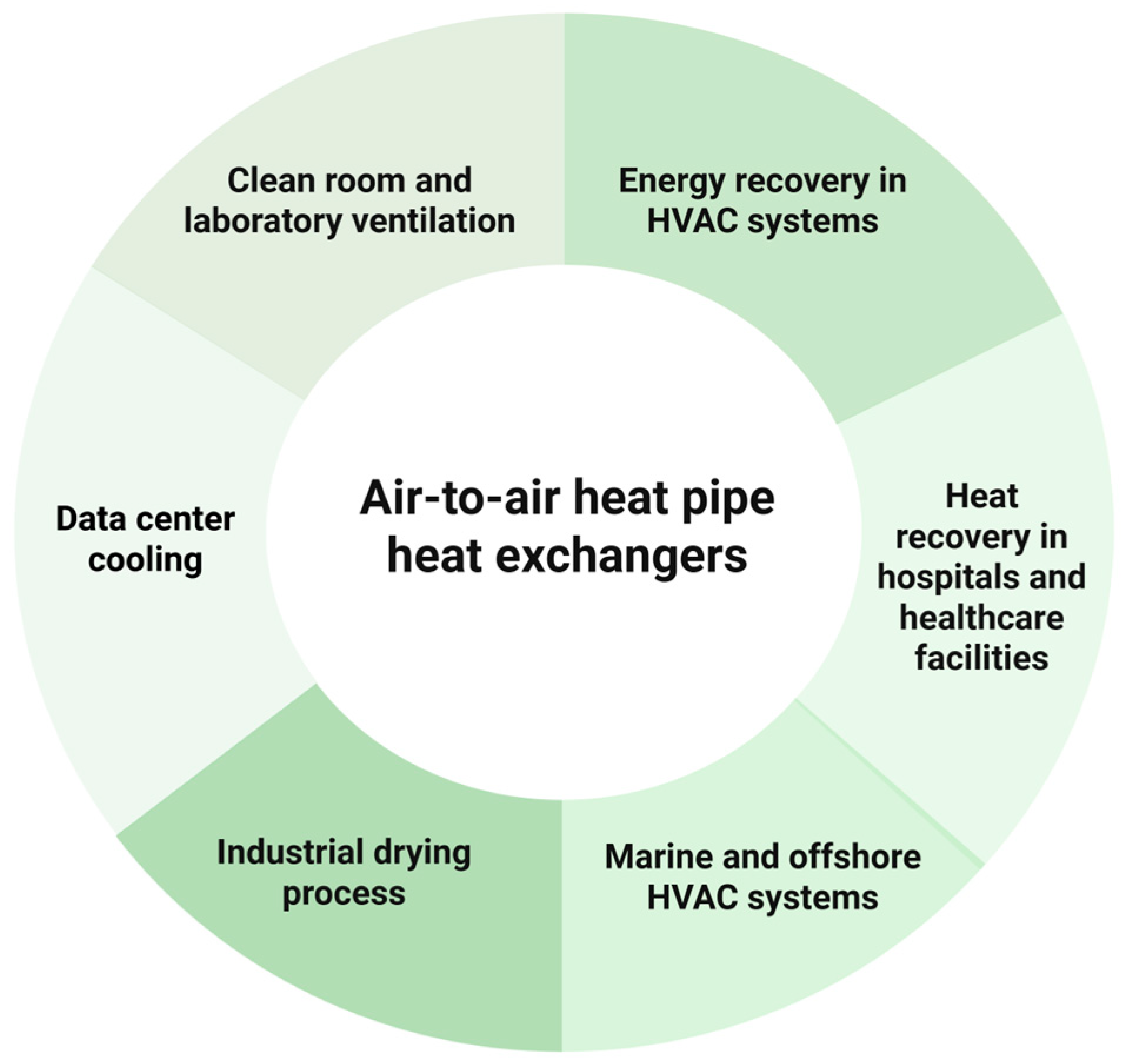
1. Introduction
2. Materials and Methods
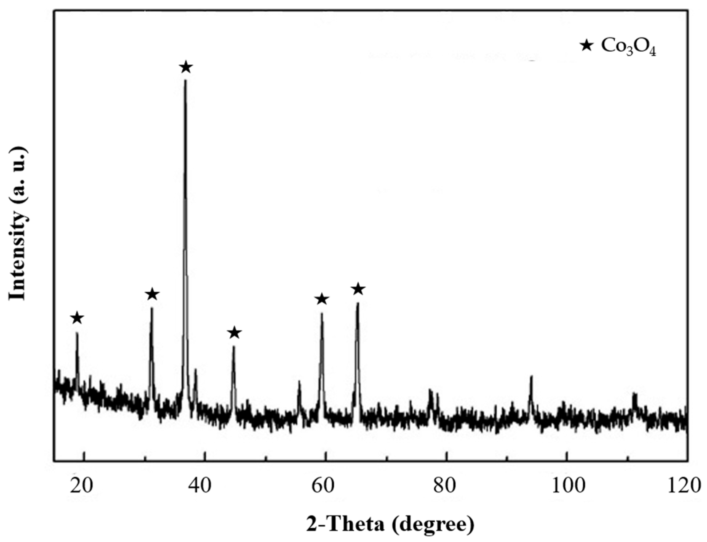
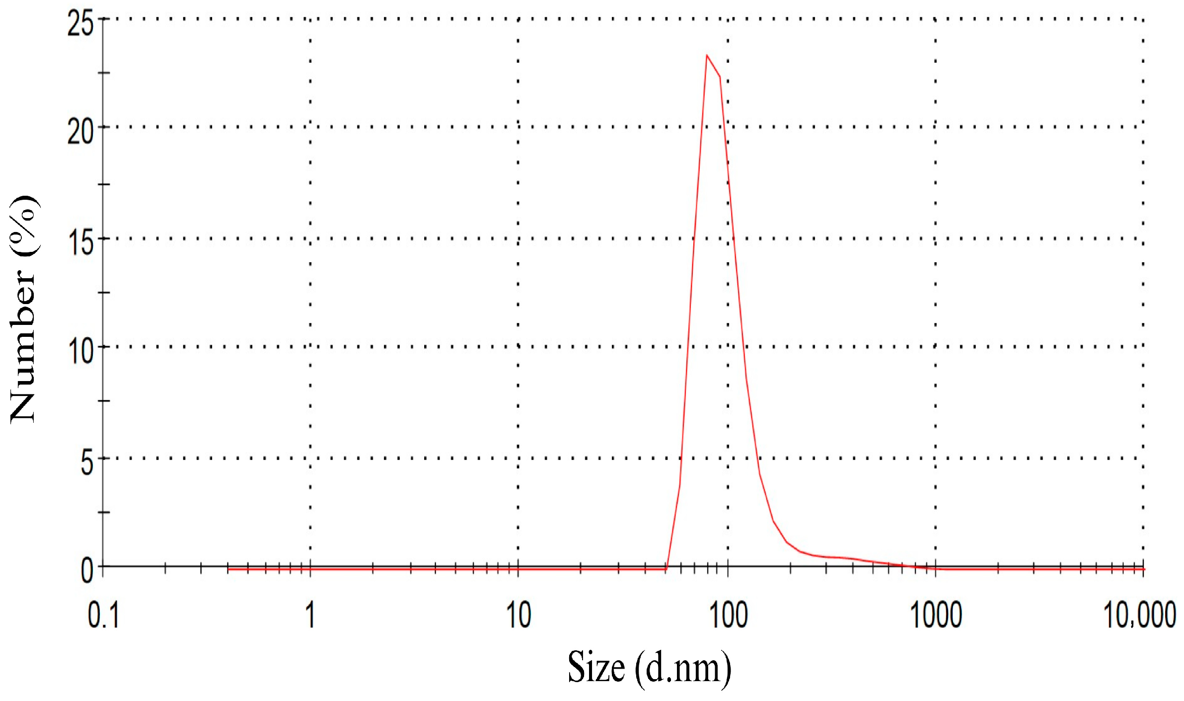
2.1. Preparation of Nanofluid
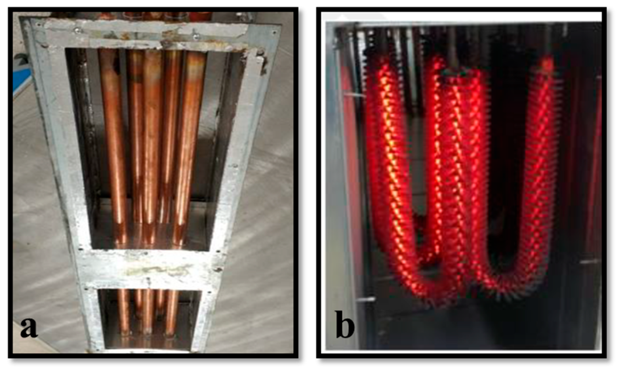
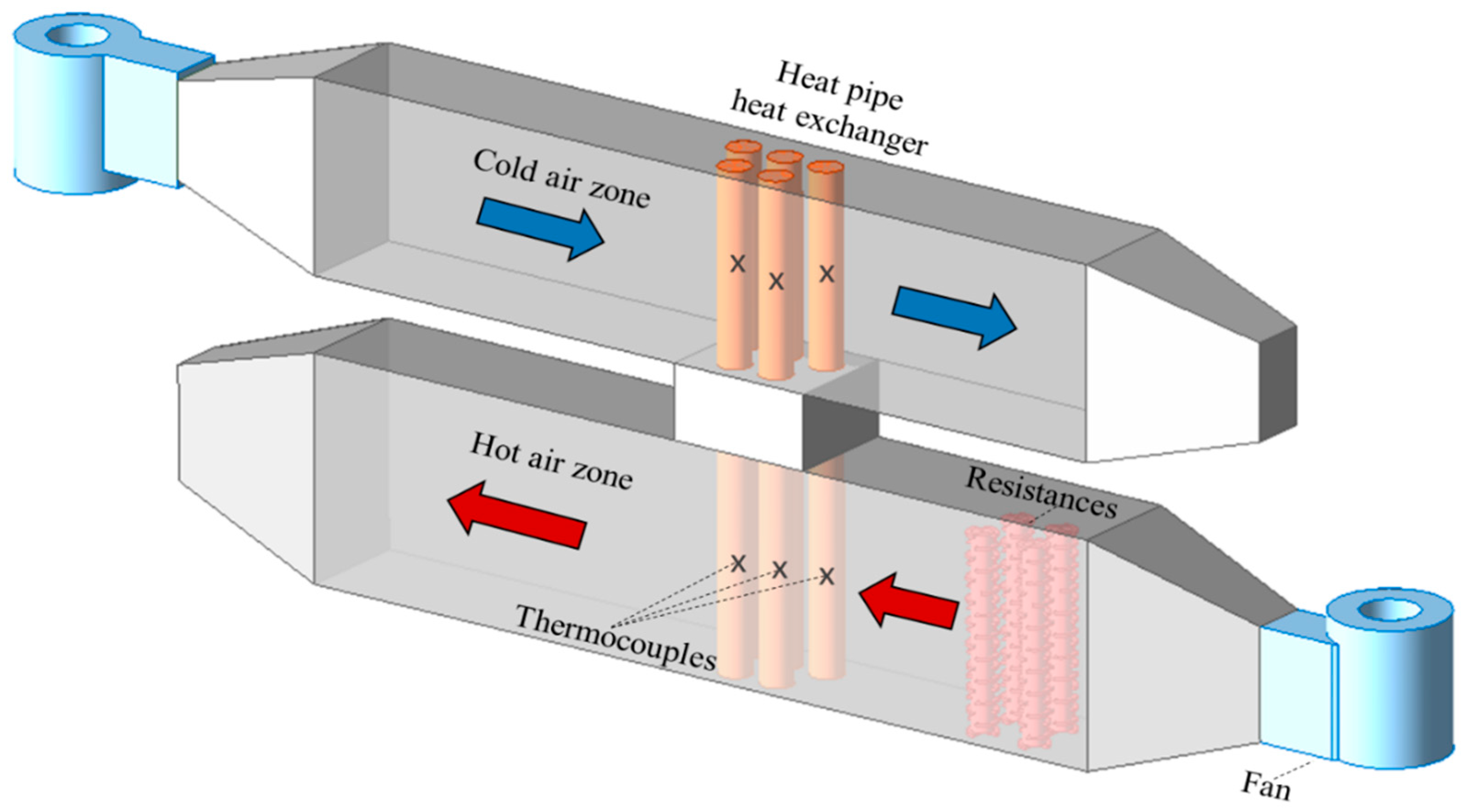
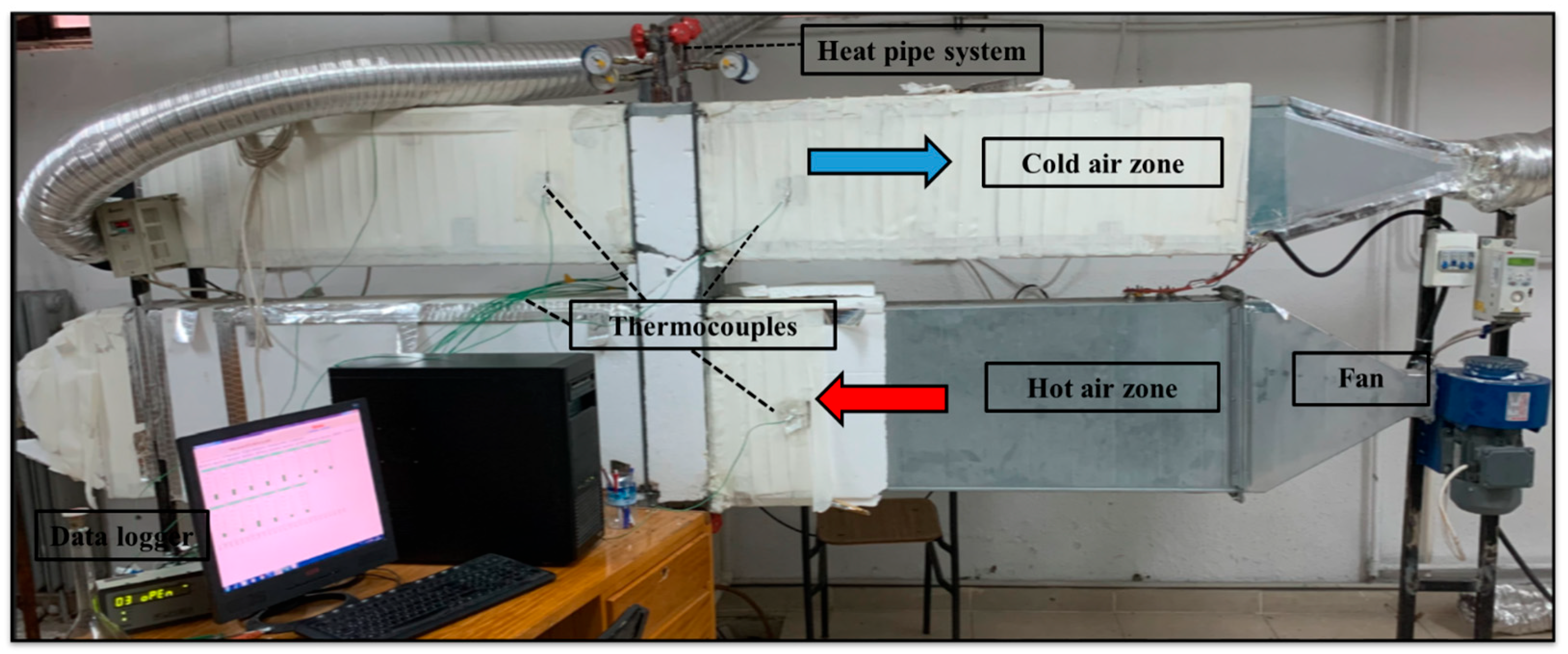
2.2. Description of the Experimental System
3. Data Processing and Uncertainty Analysis
3.1. Data Processing
3.2. Uncertainty Analysis
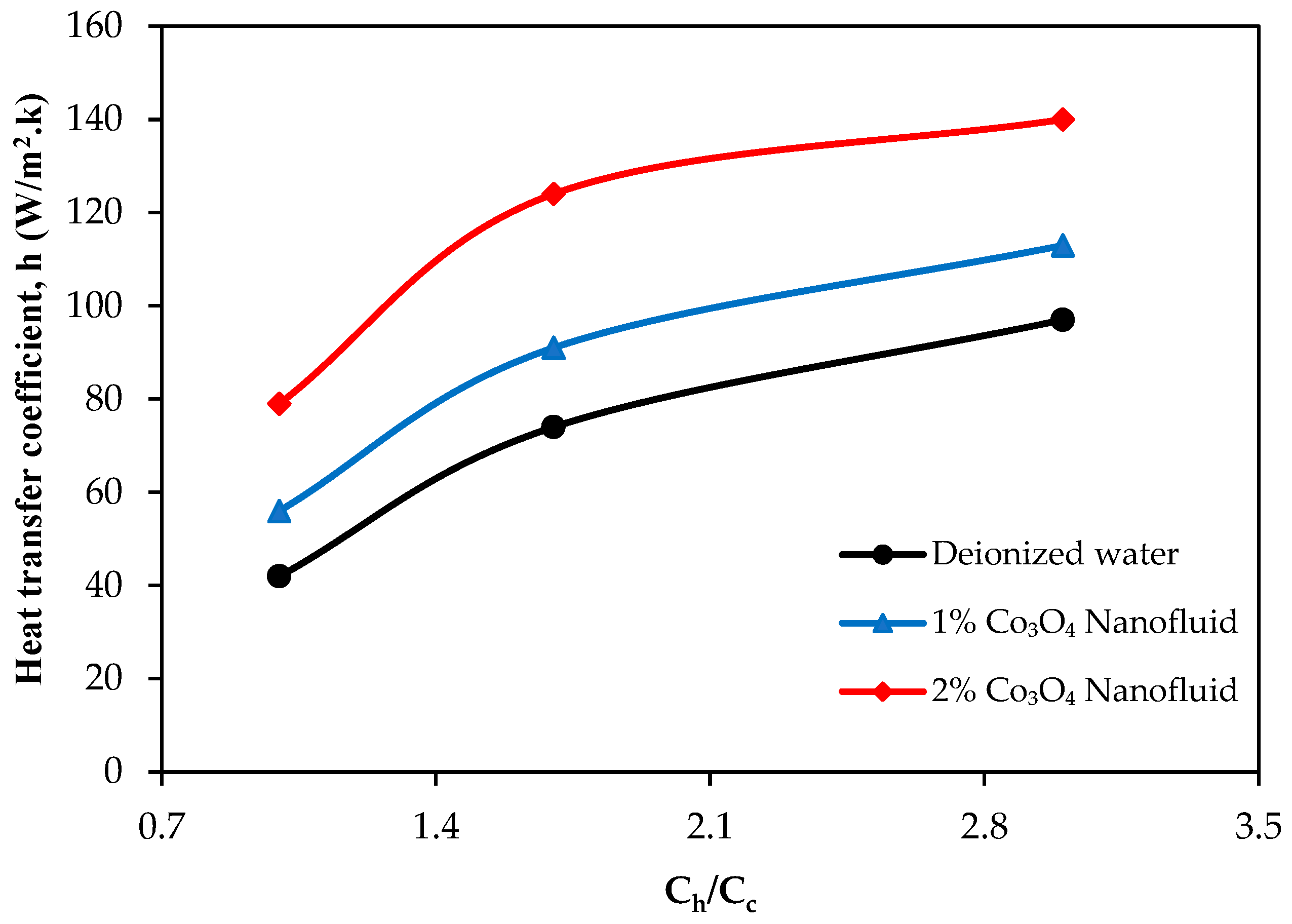
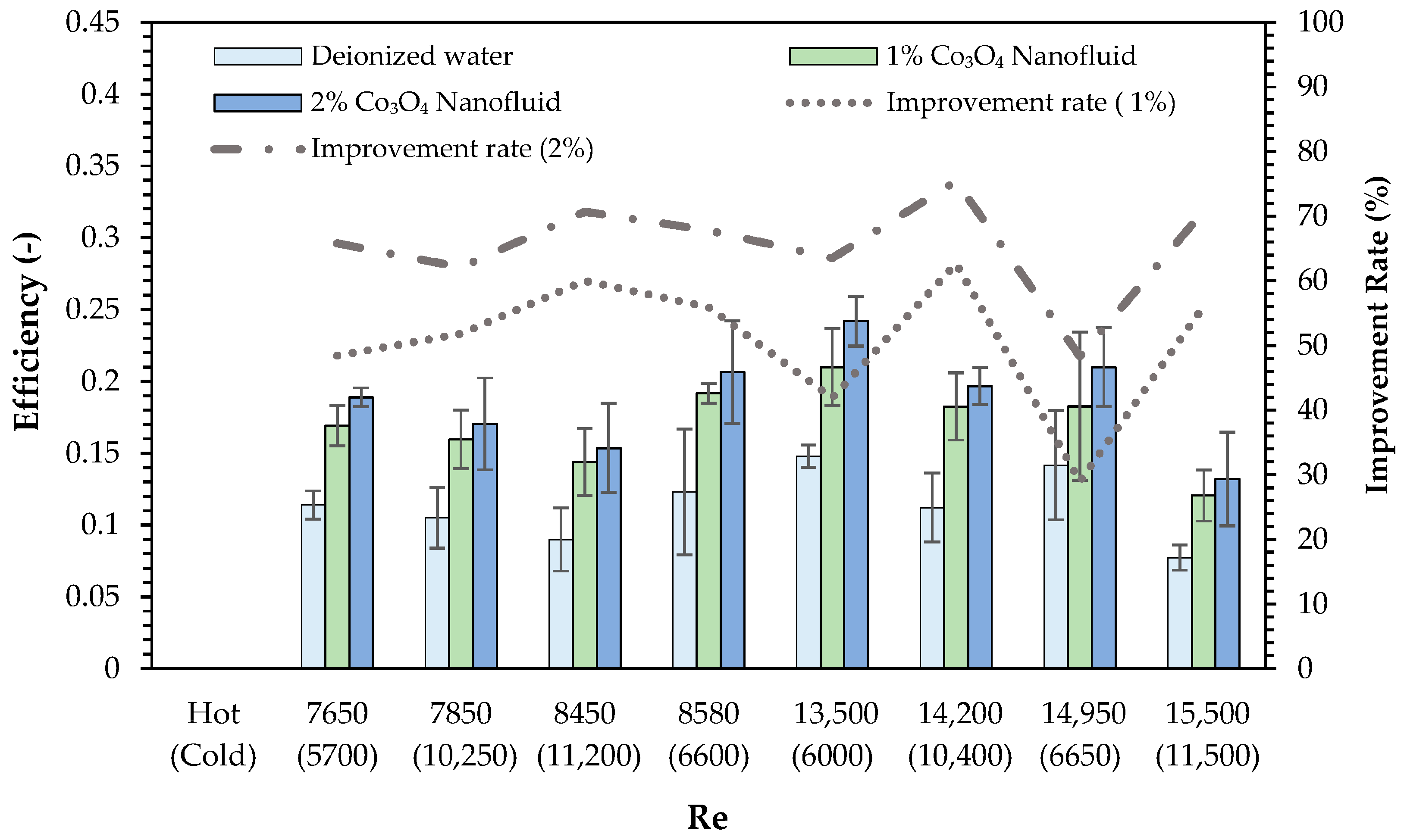
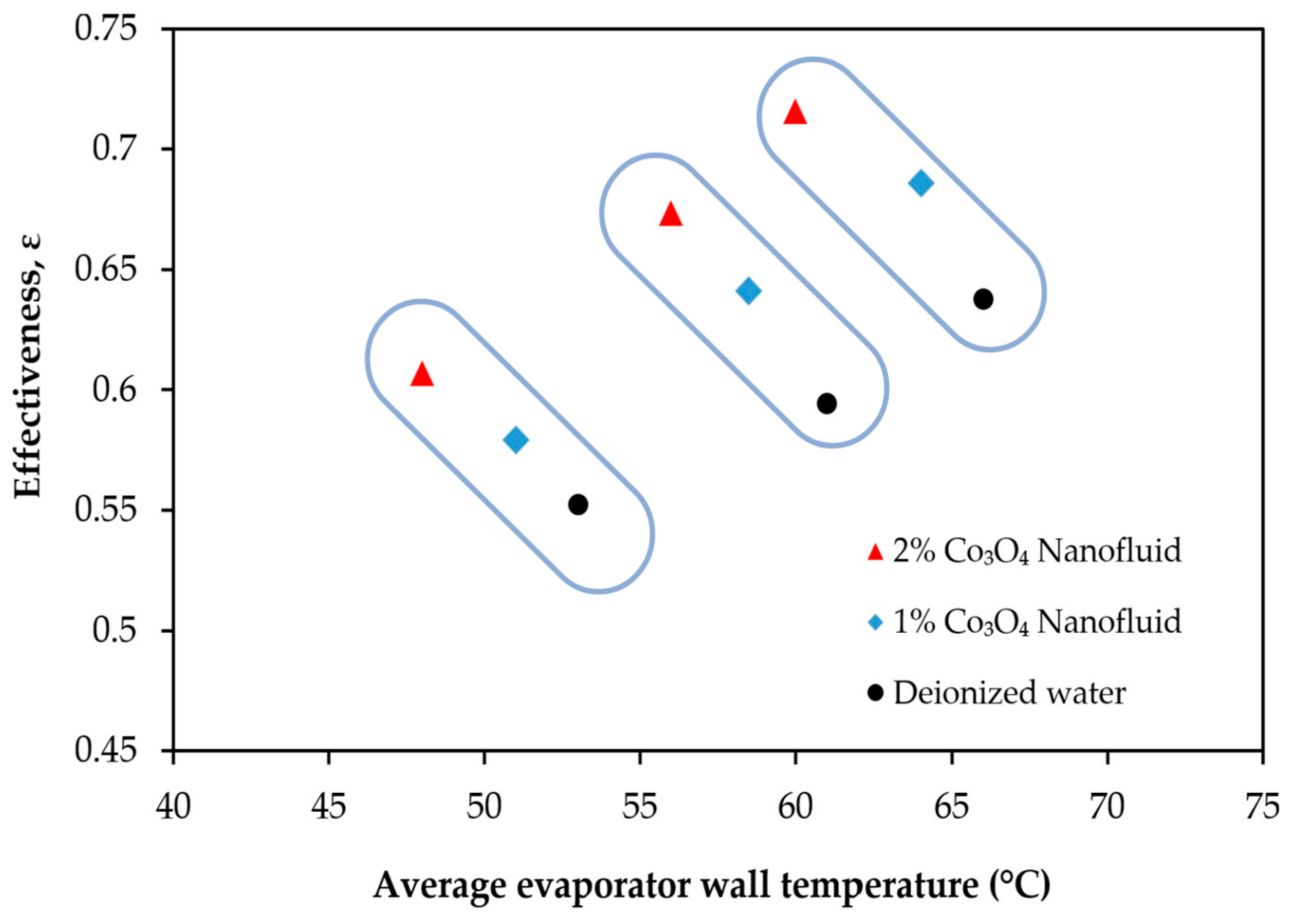
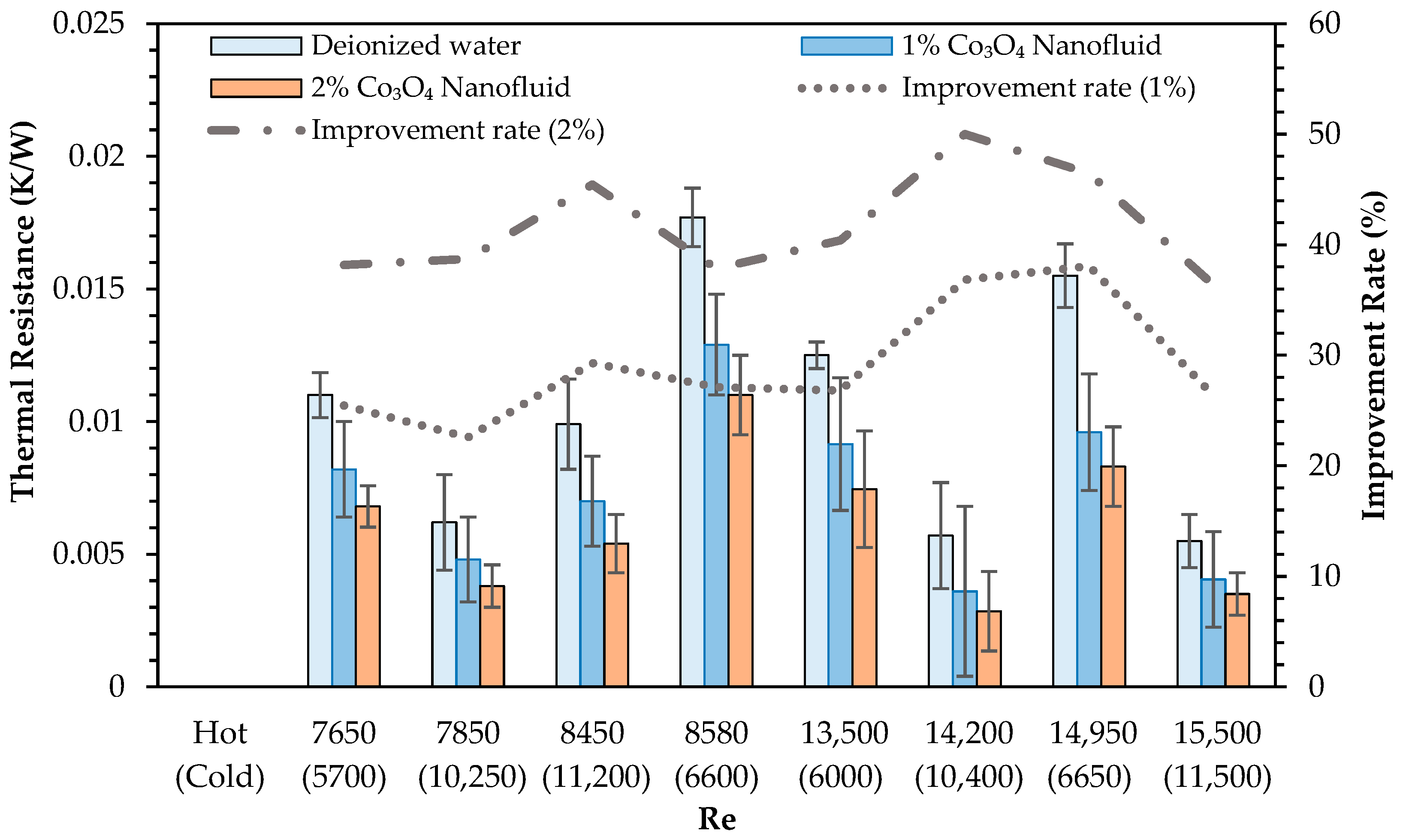
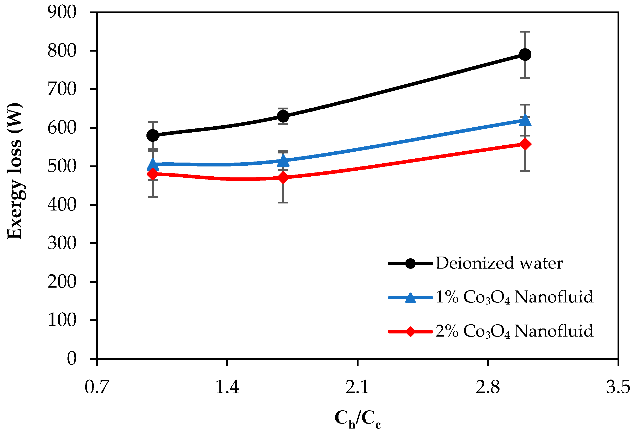
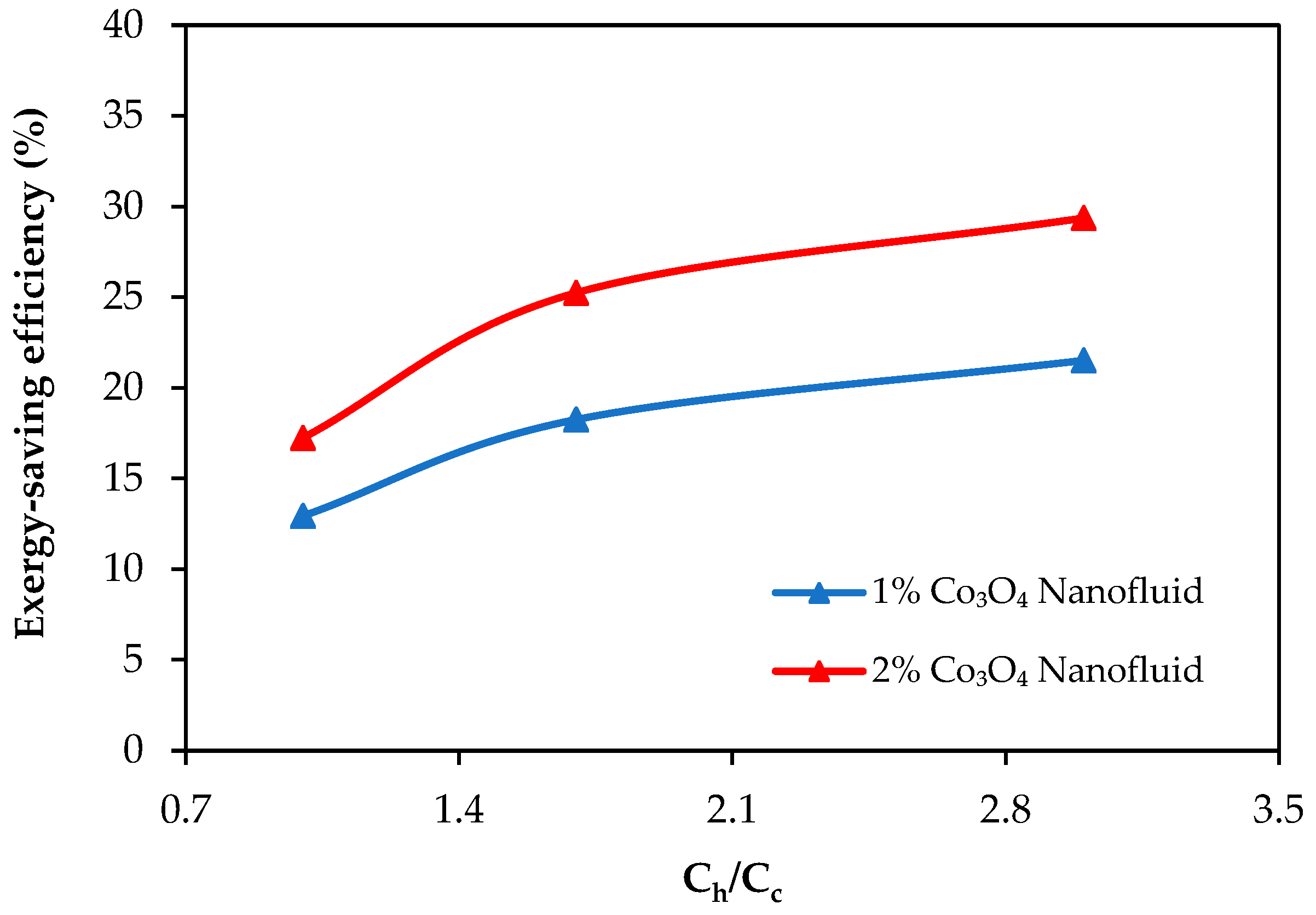
4. Results
5. Conclusions
- Turbulent flow regimes in the hot and cold air channels were confirmed under all tested conditions, ensuring consistent external convective heat transfer. This stable boundary condition enables a reliable evaluation of the relative thermal performance improvements achieved by nanoparticle-enhanced fluids within the heat pipe.
- The use of Co3O4 nanofluids substantially improved the thermal efficiency, heat transfer coefficient, and thermal effectiveness compared to deionized water. The highest thermal efficiency improvements were recorded as 62.7% and 75.4% for the 1% and 2% Co3O4 nanofluids, respectively. CB incorporation further enhanced the thermal efficiency of the 2% Co3O4 nanofluid, achieving a maximum improvement of 79.2%.
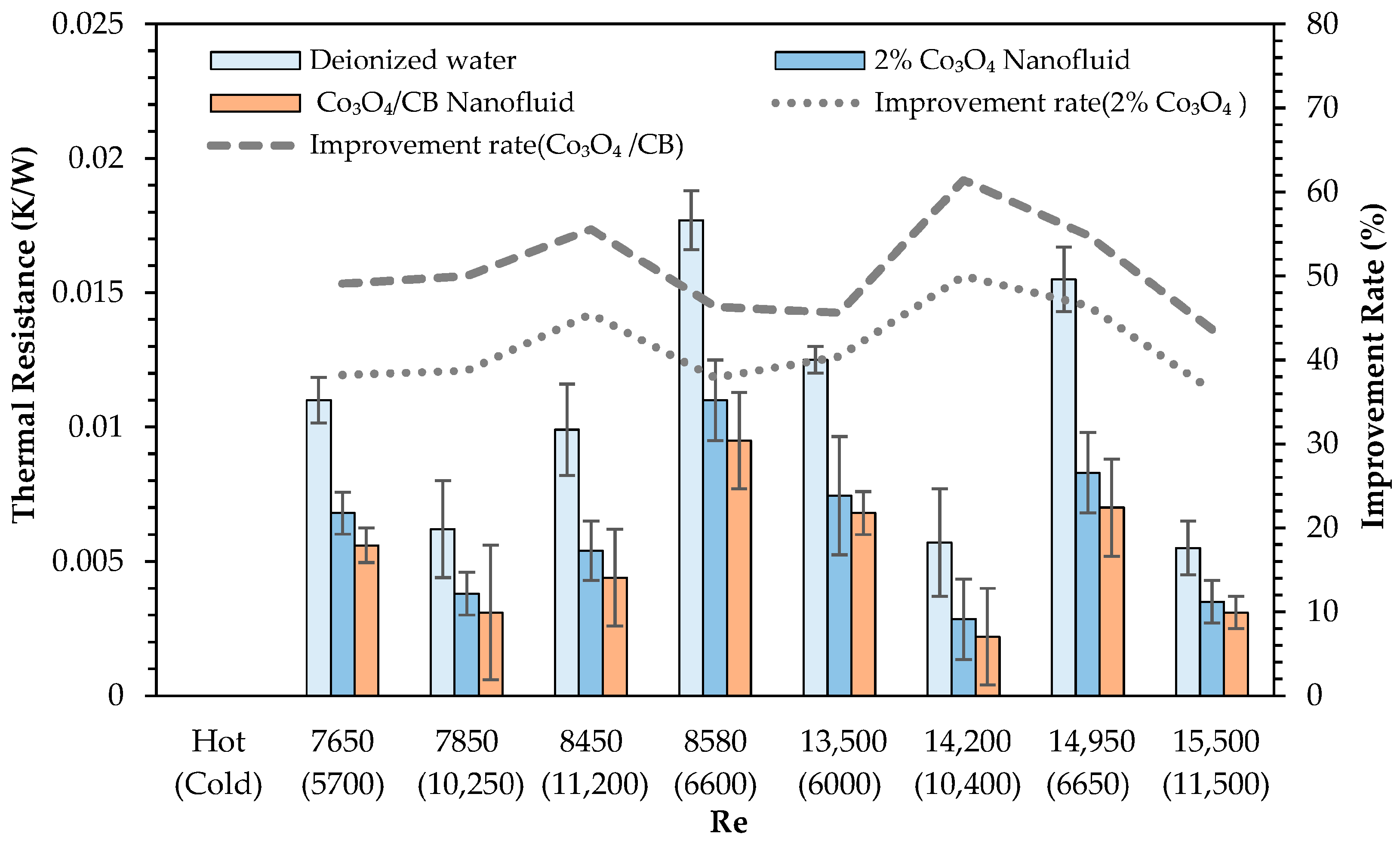
- Thermal resistance values significantly decreased with nanoparticle addition, and further reductions were obtained by introducing CB. The highest thermal resistance reduction observed was 61.4% relative to deionized water, highlighting the effective role of CB in facilitating heat transfer processes.
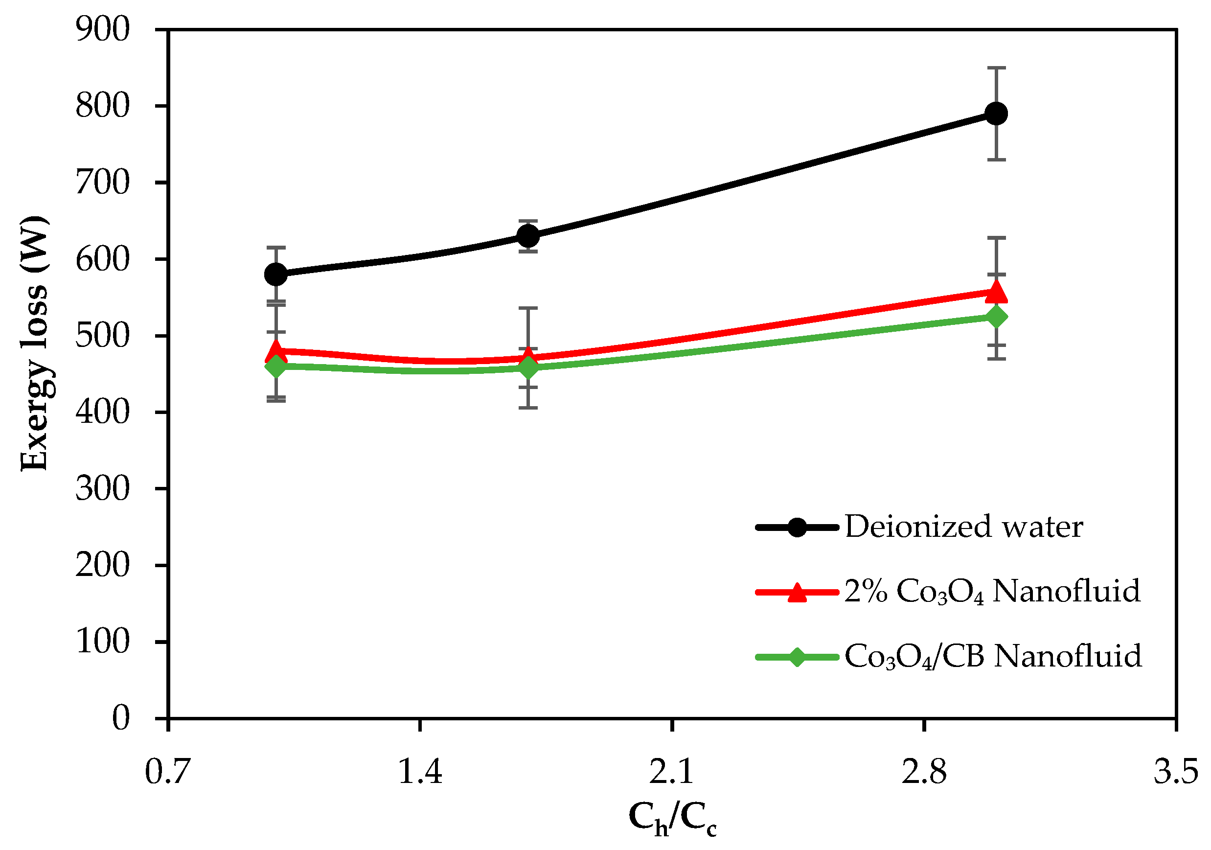
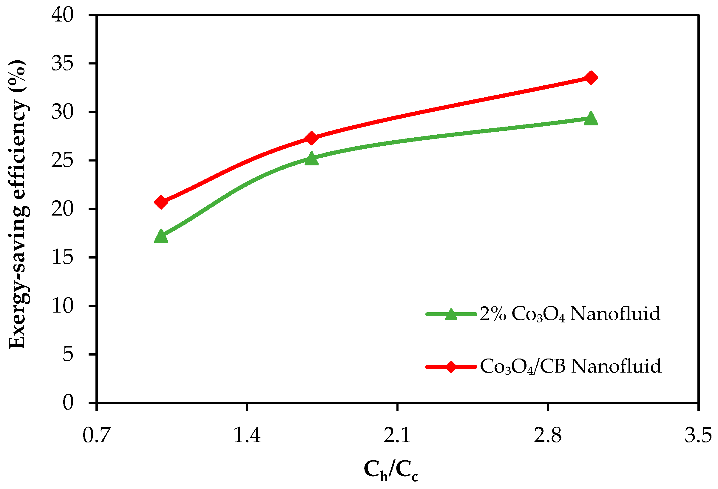
- Exergy loss decreased with the use of nanofluids, and the exergy-saving efficiency reached up to 29.3% and 33.6% with the 2% Co3O4 nanofluid and Co3O4/CB nanofluid, respectively. CB contributed to further reducing exergy losses by improving thermal dispersion and minimizing system irreversibility.
Funding
Institutional Review Board Statement
Informed Consent Statement
Data Availability Statement
Acknowledgments
Conflicts of Interest
References
- Delpech, B.; Milani, M.; Montorsi, L.; Boscardin, D.; Chauhan, A.; Almahmoud, S.; Axcell, B.; Jouhara, H. Energy Efficiency Enhancement and Waste Heat Recovery in Industrial Processes by Means of the Heat Pipe Technology: Case of the Ceramic Industry. Energy 2018, 158, 656–665. [Google Scholar] [CrossRef]
- Jouhara, H.; Khordehgah, N.; Almahmoud, S.; Delpech, B.; Chauhan, A.; Tassou, S.A. Waste Heat Recovery Technologies and Applications. Therm. Sci. Eng. Prog. 2018, 6, 268–289. [Google Scholar] [CrossRef]
- Brückner, S.; Liu, S.; Miró, L.; Radspieler, M.; Cabeza, L.F.; Lävemann, E. Industrial Waste Heat Recovery Technologies: An Economic Analysis of Heat Transformation Technologies. Appl. Energy 2015, 151, 157–167. [Google Scholar] [CrossRef]
- Jouhara, H.; Delpech, B.; Almahmoud, S.; Chauhan, A.; Al-Mansour, F.; Pusnik, M.; Buhvald, A.; Plesnik, K. Experimental Investigation on an Advanced Thermosiphon-Based Heat Exchanger for Enhanced Waste Heat Recovery in the Steel Industry. Energy 2025, 315, 134428. [Google Scholar] [CrossRef]
- Geum, G.; Kang, S.; Cho, S.; Kong, D.; Lee, S.; Seo, J.; Shin, D.H.; Lee, S.H.; Lee, J.; Lee, H. Thermal Performance Analysis of Heat Pipe Heat Exchanger for Effective Waste Heat Recovery. Int. Commun. Heat Mass Transf. 2024, 151, 107223. [Google Scholar] [CrossRef]
- Zeng, C.; Liu, S.; Shukla, A. A Review on the Air-to-Air Heat and Mass Exchanger Technologies for Building Applications. Renew. Sustain. Energy Rev. 2017, 75, 753–774. [Google Scholar] [CrossRef]
- Çiftçi, E.; Martin, K.; Sözen, A. Enhancement of Thermal Performance of the Air-To-Air Heat Pipe Heat Exchanger (AAHX) with Aluminate Spinel-Based Binary Hybrid Nanofluids. Heat Trans. Res. 2021, 52, 81–97. [Google Scholar] [CrossRef]
- Rafati Nasr, M.; Kassai, M.; Ge, G.; Simonson, C.J. Evaluation of Defrosting Methods for Air-to-Air Heat/Energy Exchangers on Energy Consumption of Ventilation. Appl. Energy 2015, 151, 32–40. [Google Scholar] [CrossRef]
- Rasouli, M.; Ge, G.; Simonson, C.J.; Besant, R.W. Uncertainties in Energy and Economic Performance of HVAC Systems and Energy Recovery Ventilators Due to Uncertainties in Building and HVAC Parameters. Appl. Therm. Eng. 2013, 50, 732–742. [Google Scholar] [CrossRef]
- Gürü, M.; Karakaya, U.; Alıcı, D.Ş.; Olgun, Ş.; Aydın, D.Y. Experimental Investigation of the Effect of Boron-Containing Nanofluid on Heat Pipe Thermal Performance. Heat Transf. Res. 2025, 56, 1–14. [Google Scholar] [CrossRef]
- Gupta, N.K.; Tiwari, A.K.; Ghosh, S.K. Heat Transfer Mechanisms in Heat Pipes Using Nanofluids—A Review. Exp. Therm. Fluid Sci. 2018, 90, 84–100. [Google Scholar] [CrossRef]
- Yılmaz Aydın, D.; Gürü, M.; Sözen, A. Enhancement of Heat Transfer Performance of a Heat Pipe by Using Calcium Magnesium Carbonate-Ethylene Glycol/Water Nanofluid with Sodium Dodecylbenzene Sulfonate. Period. Polytech. Chem. Eng. 2022, 66, 609–616. [Google Scholar] [CrossRef]
- Chaudhry, H.N.; Hughes, B.R.; Ghani, S.A. A Review of Heat Pipe Systems for Heat Recovery and Renewable Energy Applications. Renew. Sustain. Energy Rev. 2012, 16, 2249–2259. [Google Scholar] [CrossRef]
- Han, H.; Cui, X.; Zhu, Y.; Sun, S. A Comparative Study of the Behavior of Working Fluids and Their Properties on the Performance of Pulsating Heat Pipes (PHP). Int. J. Therm. Sci. 2014, 82, 138–147. [Google Scholar] [CrossRef]
- Kim, J.; Kim, S.J. Experimental Investigation on Working Fluid Selection in a Micro Pulsating Heat Pipe. Energy Convers. Manag. 2020, 205, 112462. [Google Scholar] [CrossRef]
- Pathak, S.K.; Kumar, R.; Goel, V.; Pandey, A.K.; Tyagi, V.V. Recent Advancements in Thermal Performance of Nano-Fluids Charged Heat Pipes Used for Thermal Management Applications: A Comprehensive Review. Appl. Therm. Eng. 2022, 216, 119023. [Google Scholar] [CrossRef]
- Yılmaz Aydın, D.; Gürü, M. Nanofluids: Preparation, Stability, Properties, and Thermal Performance in Terms of Thermo-Hydraulic, Thermodynamics and Thermo-Economic Analysis. J. Therm. Anal. Calorim. 2022, 147, 7631–7664. [Google Scholar] [CrossRef]
- Yu, Y.; Du, J.; Hou, J.; Jin, X.; Wang, R. Investigation into the Underlying Mechanisms of the Improvement of Thermal Conductivity of the Hybrid Nanofluids. Int. J. Heat Mass Transf. 2024, 226, 125468. [Google Scholar] [CrossRef]
- Behera, U.S.; Sangwai, J.S.; Byun, H.-S. A Comprehensive Review on the Recent Advances in Applications of Nanofluids for Effective Utilization of Renewable Energy. Renew. Sustain. Energy Rev. 2025, 207, 114901. [Google Scholar] [CrossRef]
- Kumar, S.; Kaur, A.; Gaur, J.; Singh, P.; Kaur, H.; Kaushal, S.; Dalal, J.; Misra, M. State-of-the-Art in Co3O4 Nanoparticle Synthesis and Applications: Toward a Sustainable Future. ChemistrySelect 2025, 10, e202405147. [Google Scholar] [CrossRef]
- Sekhar, T.; Nandan, G.; Prakash, R.; Muthuraman, M. Investigations on Viscosity and Thermal Conductivity of Cobalt Oxide- Water Nano Fluid. Mater. Today Proc. 2018, 5, 6176–6182. [Google Scholar] [CrossRef]
- Elsaid, A.M. Experimental Study on the Heat Transfer Performance and Friction Factor Characteristics of Co3O4 and Al2O3 Based H2O/(CH2OH)2 Nanofluids in a Vehicle Engine Radiator. Int. Commun. Heat Mass Transf. 2019, 108, 104263. [Google Scholar] [CrossRef]
- Said, Z.; Ghodbane, M.; Sundar, L.S.; Tiwari, A.K.; Sheikholeslami, M.; Boumeddane, B. Heat Transfer, Entropy Generation, Economic and Environmental Analyses of Linear Fresnel Reflector Using Novel rGO-Co3O4 Hybrid Nanofluids. Renew. Energy 2021, 165, 420–437. [Google Scholar] [CrossRef]
- Syam Sundar, L.; Venkata Ramana, E.; Said, Z.; Pereira, A.M.B.; Sousa, A.C.M. Heat Transfer of rGO/CO3O4 Hybrid Nanomaterial-Based Nanofluids and Twisted Tape Configurations in a Tube. J. Therm. Sci. Eng. Appl. 2021, 13, 031004. [Google Scholar] [CrossRef]
- Syam Sundar, L.; Said, Z.; Saleh, B.; Singh, M.K.; Sousa, A.C.M. Combination of Co3O4 Deposited rGO Hybrid Nanofluids and Longitudinal Strip Inserts: Thermal Properties, Heat Transfer, Friction Factor, and Thermal Performance Evaluations. Therm. Sci. Eng. Prog. 2020, 20, 100695. [Google Scholar] [CrossRef]
- Sundar, L.S.; Mathew, B.; Sefelnasr, A.; Sherif, M.; Sharma, K.V. Enhanced Heat Transfer and Thermal Performance Factor of Coiled Wire Inserted rGO/Co3O4 Hybrid Nanofluid Circulating in a Horizontal Tube. J. Enhanc. Heat Transf. 2021, 28, 77–103. [Google Scholar] [CrossRef]
- Syam Sundar, L.; Singh, M.K.; Ferro, M.C.; Sousa, A.C.M. Experimental Investigation of the Thermal Transport Properties of Graphene Oxide/Co3O4 Hybrid Nanofluids. Int. Commun. Heat Mass Transf. 2017, 84, 1–10. [Google Scholar] [CrossRef]
- Sarafraz, M.M.; Silakhori, M.; Madani, S.A.; Kiamahalleh, M.V.; Pourmehran, O. Thermal and Hydraulic Performance of a Heat Exchanger Working with Carbon-Water Nanofluid. Heat Mass Transf. 2019, 55, 3443–3453. [Google Scholar] [CrossRef]
- Shiravi, A.H.; Shafiee, M.; Firoozzadeh, M.; Bostani, H.; Bozorgmehrian, M. Experimental Study on Convective Heat Transfer and Entropy Generation of Carbon Black Nanofluid Turbulent Flow in a Helical Coiled Heat Exchanger. J. Therm. Anal. Calorim. 2021, 145, 597–607. [Google Scholar] [CrossRef]
- Firoozzadeh, M.; Shiravi, A.H.; Lotfi, M.; Aidarova, S.; Sharipova, A. Optimum Concentration of Carbon Black Aqueous Nanofluid as Coolant of Photovoltaic Modules: A Case Study. Energy 2021, 225, 120219. [Google Scholar] [CrossRef]
- Gimeno-Furio, A.; Hernandez, L.; Navarrete, N.; Mondragon, R. Characterisation Study of a Thermal Oil-Based Carbon Black Solar Nanofluid. Renew. Energy 2019, 140, 493–500. [Google Scholar] [CrossRef]
- Abdelrahim, K.A.; Ramaswamy, H.S. High Temperature/Pressure Rheology of Carboxymethyl Cellulose (CMC). Food Res. Int. 1995, 28, 285–290. [Google Scholar] [CrossRef]
- Hojjat, M.; Etemad, S.G.; Bagheri, R.; Thibault, J. Rheological Characteristics of Non-Newtonian Nanofluids: Experimental Investigation. Int. Commun. Heat Mass Transf. 2011, 38, 144–148. [Google Scholar] [CrossRef]
- Yaşar, F.; Toğrul, H.; Arslan, N. Flow Properties of Cellulose and Carboxymethyl Cellulose from Orange Peel. J. Food Eng. 2007, 81, 187–199. [Google Scholar] [CrossRef]
- Bazdidi-Tehrani, F.; Khanmohamadi, S.M.; Vasefi, S.I. Evaluation of Turbulent Forced Convection of Non-Newtonian Aqueous Solution of CMC/CuO Nanofluid in a Tube with Twisted Tape Inserts. Adv. Powder Technol. 2020, 31, 1100–1113. [Google Scholar] [CrossRef]
- Zainith, P.; Mishra, N.K. Experimental Investigations on Stability and Viscosity of Carboxymethyl Cellulose (CMC)-Based Non-Newtonian Nanofluids with Different Nanoparticles with the Combination of Distilled Water. Int. J. Thermophys. 2021, 42, 137. [Google Scholar] [CrossRef]
- Abdallah, A.S.; Yasin, N.J.; Ameen, H.A. Thermal Performance Enhancement of Heat Pipe Heat Exchanger in the Air-Conditioning System by Using Nanofluid. Front. Heat Mass Transf. 2022, 18, 1–7. [Google Scholar] [CrossRef]
- Herrera, B.; Gallego, A.; Cacua, K. Experimental Evaluation of a Thermosyphon-Based Heat Exchanger Working with a Graphene Oxide (GO) Nanofluid in a Cogeneration System. Therm. Sci. Eng. Prog. 2021, 24, 100949. [Google Scholar] [CrossRef]
- Sethuraman, R.; Muthuvelan, T.; Mahadevan, S.; Dhairiyasamy, R. Maximizing Thermal Performance of Heat Pipe Heat Exchangers for Industrial Applications Using Silver Nanofluids. Int. J. Thermophys. 2024, 45, 55. [Google Scholar] [CrossRef]
- Chaudhari, V.; Dharmadhikari, M.; Kolhe, V. Experimental Analysis of Thermal Performance for Heat Pipe Heat Exchanger with ZnO Nanofluid. Lett. Appl. NanoBioSci 2024, 13, 80. [Google Scholar] [CrossRef]
- Babat, R.A.A.; Martin, K.; Çiftçi, E.; Sözen, A. Experimental Study on the Utilization of Magnetic Nanofluids in an Air-to-Air Heat Pipe Heat Exchanger. Chem. Eng. Commun. 2023, 210, 687–697. [Google Scholar] [CrossRef]
- Martin, K.; Boran, K. Numerical Analysis of an Air-to-Air Heat Pipe Heat Exchanger and Comparison with Experimental Data. Int. J. Ambient Energy 2022, 43, 8592–8601. [Google Scholar] [CrossRef]
- Öztürk, A. An Experimental Study on the Thermal Efficiency of an Air-to-Air Heat Exchanger with Ethylene Glycol (EG)-Based Hybrid Nanofluid Al2O3 + TiO2. Heat Trans. Res. 2022, 53, 59–73. [Google Scholar] [CrossRef]
- Nam, K.-H.; Hwa Chae, K.; Choi, J.-H.; Jeon, K.-J.; Park, C.-M. Superior Carbon Black: High-Performance Anode and Conducting Additive for Rechargeable Li- and Na-Ion Batteries. Chem. Eng. J. 2021, 417, 129242. [Google Scholar] [CrossRef]
- Yılmaz Aydın, D.; Çiftçi, E.; Gürü, M.; Sözen, A. The Impacts of Nanoparticle Concentration and Surfactant Type on Thermal Performance of A Thermosyphon Heat Pipe Working With Bauxite Nanofluid. Energy Sources Part A Recovery Util. Environ. Eff. 2021, 43, 1524–1548. [Google Scholar] [CrossRef]
- Khanlari, A.; Yılmaz Aydın, D.; Sözen, A.; Gürü, M.; Variyenli, H.İ. Investigation of the Influences of Kaolin-Deionized Water Nanofluid on the Thermal Behavior of Concentric Type Heat Exchanger. Heat Mass Transf. 2020, 56, 1453–1462. [Google Scholar] [CrossRef]
- Yilmaz Aydin, D.; Gürü, M.; Sözen, A.; Çiftçi, E. Investigation of the Effects of Base Fluid Type of the Nanofluid on Heat Pipe Performance. Proc. Inst. Mech. Eng. Part A J. Power Energy 2021, 235, 124–138. [Google Scholar] [CrossRef]
- Aydın, D.Y.; Gürü, M.; Sözen, A. Experimental Investigation on Thermal Performance of Thermosyphon Heat Pipe Using Dolomite/Deionized Water Nanofluid Depending on Nanoparticle Concentration and Surfactant Type. Heat Trans. Res. 2020, 51, 1073–1085. [Google Scholar] [CrossRef]
- Ali, S.M.; Sarsam, W.S. Theoretical and Experimental Investigation of a Heat Pipe Heat Exchanger for Energy Recovery of Exhaust Air. Heat Trans. 2022, 51, 3600–3619. [Google Scholar] [CrossRef]
- Bahiraei, M.; Khosravi, R.; Heshmatian, S. Assessment and Optimization of Hydrothermal Characteristics for a Non-Newtonian Nanofluid Flow within Miniaturized Concentric-Tube Heat Exchanger Considering Designer’s Viewpoint. Appl. Therm. Eng. 2017, 123, 266–276. [Google Scholar] [CrossRef]
- Bahiraei, M.; Alighardashi, M. Investigating Non-Newtonian Nanofluid Flow in a Narrow Annulus Based on Second Law of Thermodynamics. J. Mol. Liq. 2016, 219, 117–127. [Google Scholar] [CrossRef]
- Lin, Y.; Zheng, L.; Zhang, X.; Ma, L.; Chen, G. MHD Pseudo-Plastic Nanofluid Unsteady Flow and Heat Transfer in a Finite Thin Film over Stretching Surface with Internal Heat Generation. Int. J. Heat Mass Transf. 2015, 84, 903–911. [Google Scholar] [CrossRef]
- Brinkman, H.C. The Viscosity of Concentrated Suspensions and Solutions. J. Chem. Phys. 1952, 20, 571. [Google Scholar] [CrossRef]
- Khairul, M.A.; Alim, M.A.; Mahbubul, I.M.; Saidur, R.; Hepbasli, A.; Hossain, A. Heat Transfer Performance and Exergy Analyses of a Corrugated Plate Heat Exchanger Using Metal Oxide Nanofluids. Int. Commun. Heat Mass Transf. 2014, 50, 8–14. [Google Scholar] [CrossRef]
- Aydın, D.Y.; Aydin, E.; Gürü, M. The Effects of Particle Mass Fraction and Static Magnetic Field on the Thermal Performance of NiFe2O4 Nanofluid in a Heat Pipe. Int. J. Therm. Sci. 2023, 183, 107875. [Google Scholar] [CrossRef]
- Jouhara, H.; Merchant, H. Experimental Investigation of a Thermosyphon Based Heat Exchanger Used in Energy Efficient Air Handling Units. Energy 2012, 39, 82–89. [Google Scholar] [CrossRef]
- Srimuang, W.; Amatachaya, P. A Review of the Applications of Heat Pipe Heat Exchangers for Heat Recovery. Renew. Sustain. Energy Rev. 2012, 16, 4303–4315. [Google Scholar] [CrossRef]
- Abd El-Baky, M.A.; Mohamed, M.M. Heat Pipe Heat Exchanger for Heat Recovery in Air Conditioning. Appl. Therm. Eng. 2007, 27, 795–801. [Google Scholar] [CrossRef]
- Sözen, A.; Filiz, Ç.; Aytaç, İ.; Martin, K.; Ali, H.M.; Boran, K.; Yetişken, Y. Upgrading of the Performance of an Air-to-Air Heat Exchanger Using Graphene/Water Nanofluid. Int. J. Thermophys. 2021, 42, 35. [Google Scholar] [CrossRef]
- Esfahani, M.R.; Languri, E.M. Exergy Analysis of a Shell-and-Tube Heat Exchanger Using Graphene Oxide Nanofluids. Exp. Therm. Fluid Sci. 2017, 83, 100–106. [Google Scholar] [CrossRef]
- Khodami, R.; Abbas Nejad, A.; Ali Khabbaz, M.R. Experimental Investigation of Energy and Exergy Efficiency of a Pulsating Heat Pipe for Chimney Heat Recovery. Sustain. Energy Technol. Assess. 2016, 16, 11–17. [Google Scholar] [CrossRef]


| Nanofluid | Concentration | Results | Ref. |
|---|---|---|---|
| CuO/water | 1–5% w/w |
| [37] |
| Graphene oxide/water | 0.1% w/w |
| [38] |
| Ag/water | 1% v/v |
| [39] |
| ZnO/water | 0–2% w/w |
| [40] |
| Fe2O3/water | 0.5–2% w/w |
| [41] |
| CuO-Fe/water | %2 w/w |
| [42] |
| Al2O3-TiO2/EG | - |
| [43] |
| Co3O4 | 1–2% w/w |
| This work |
| Co3O4/CB | 2%/0.4% w/w |
| This work |
| Heat Pipe Material | Copper |
|---|---|
| Total length of the heat pipe | 1 m |
| Evaporator section length | 450 mm |
| Condenser section length | 400 mm |
| Adiabatic section length | 150 mm |
| Inclination angle | 90° |
| Number of heat pipes | 5 units |
| Outer diameter of the heat pipe | 25.4 mm |
| Inner diameter of the heat pipe | 23.4 mm |
| Wall thickness | 1 mm |
| Test Case No. | Heating Power (W) | Hot Air Velocity (m/s) | Cold Air Velocity (m/s) |
|---|---|---|---|
| 1 | 1000 | 0.555 | 0.437 |
| 2 | 1000 | 0.555 | 0.751 |
| 3 | 1000 | 0.985 | 0.437 |
| 4 | 1000 | 0.985 | 0.751 |
| 5 | 2000 | 0.555 | 0.437 |
| 6 | 2000 | 0.555 | 0.751 |
| 7 | 2000 | 0.985 | 0.437 |
| 8 | 2000 | 0.985 | 0.751 |
Disclaimer/Publisher’s Note: The statements, opinions and data contained in all publications are solely those of the individual author(s) and contributor(s) and not of MDPI and/or the editor(s). MDPI and/or the editor(s) disclaim responsibility for any injury to people or property resulting from any ideas, methods, instructions or products referred to in the content. |
© 2025 by the author. Licensee MDPI, Basel, Switzerland. This article is an open access article distributed under the terms and conditions of the Creative Commons Attribution (CC BY) license (https://creativecommons.org/licenses/by/4.0/).
Share and Cite
Yilmaz Aydin, D. Thermal and Exergetic Performance Analyses of a Heat Pipe Heat Exchanger Using CMC/Co3O4-Based Non-Newtonian Nanofluids. Appl. Sci. 2025, 15, 7831. https://doi.org/10.3390/app15147831
Yilmaz Aydin D. Thermal and Exergetic Performance Analyses of a Heat Pipe Heat Exchanger Using CMC/Co3O4-Based Non-Newtonian Nanofluids. Applied Sciences. 2025; 15(14):7831. https://doi.org/10.3390/app15147831
Chicago/Turabian StyleYilmaz Aydin, Duygu. 2025. "Thermal and Exergetic Performance Analyses of a Heat Pipe Heat Exchanger Using CMC/Co3O4-Based Non-Newtonian Nanofluids" Applied Sciences 15, no. 14: 7831. https://doi.org/10.3390/app15147831
APA StyleYilmaz Aydin, D. (2025). Thermal and Exergetic Performance Analyses of a Heat Pipe Heat Exchanger Using CMC/Co3O4-Based Non-Newtonian Nanofluids. Applied Sciences, 15(14), 7831. https://doi.org/10.3390/app15147831