
Antistatic Melt-Electrowritten Biodegradable Mesh Implants for Enhanced Pelvic Organ Prolapse Repair

 , , , , ,
  , ,
, ,  , and
, and 
Abstract
1. Introduction
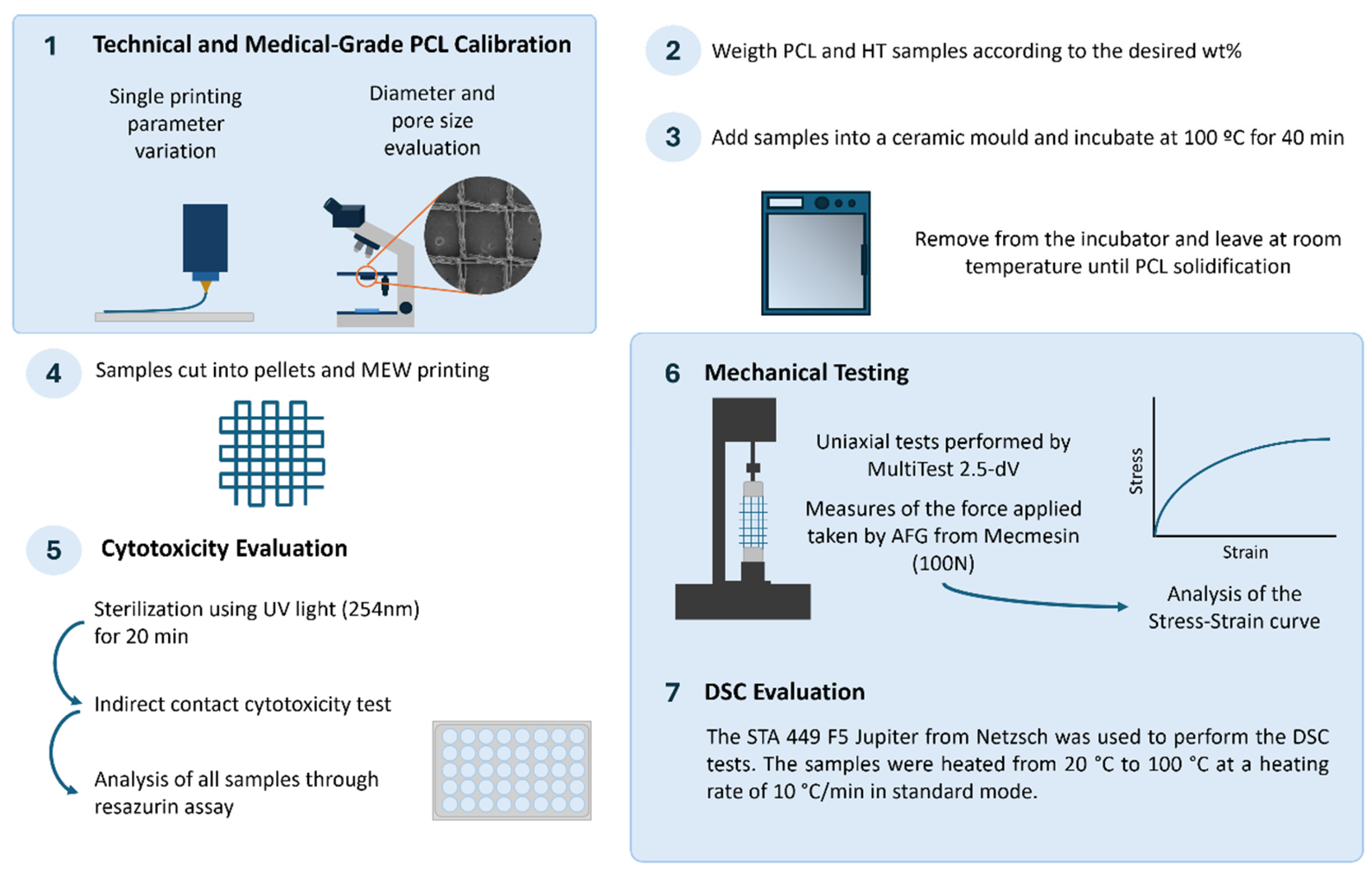
2. Methodology
2.1. Polymer
2.2. Antistatic Agent
2.3. MEW Device
2.4. MEW Device Calibration
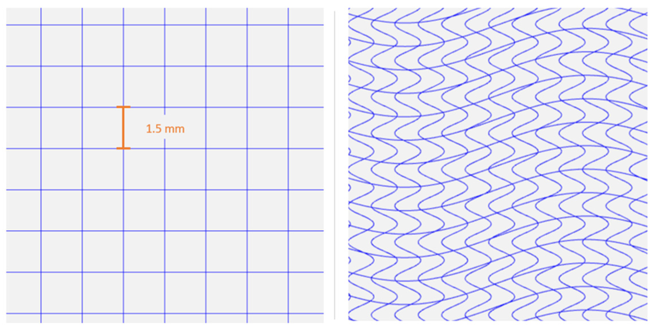
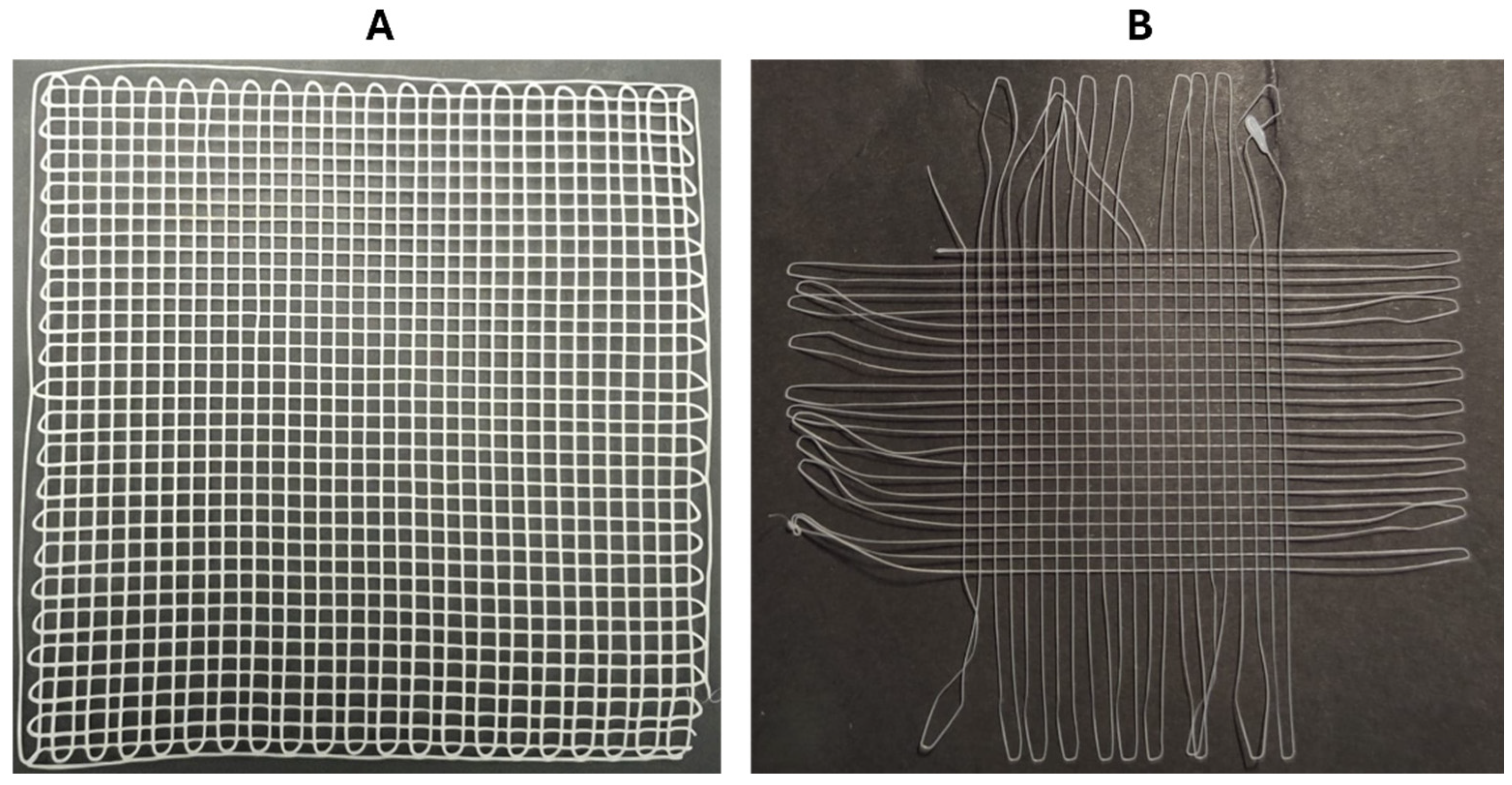
2.5. Meshes Design
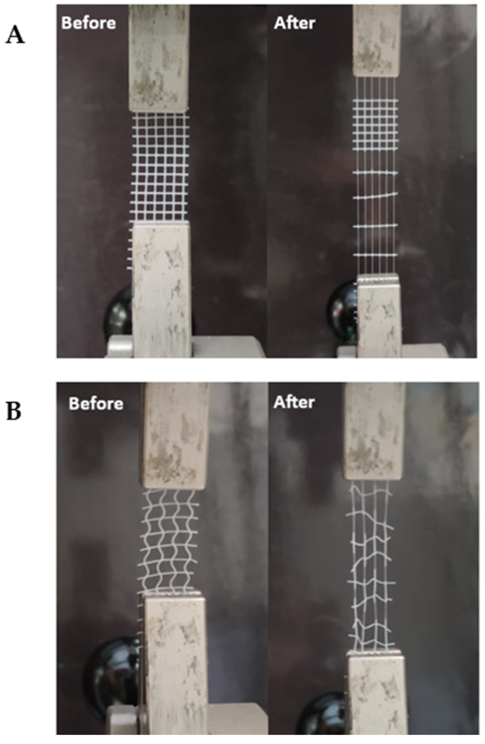
2.6. Uniaxial Tensile Testing
2.7. Differential Scanning Calorimetry
2.8. Melt Blending
2.9. Cytotoxicity Evaluation of MEW Meshes
2.10. Statistical Analysis
3. Results
3.1. Technical-Grade PCL Calibration
3.1.1. Temperature
3.1.2. Collector’s Speed
3.1.3. Voltage
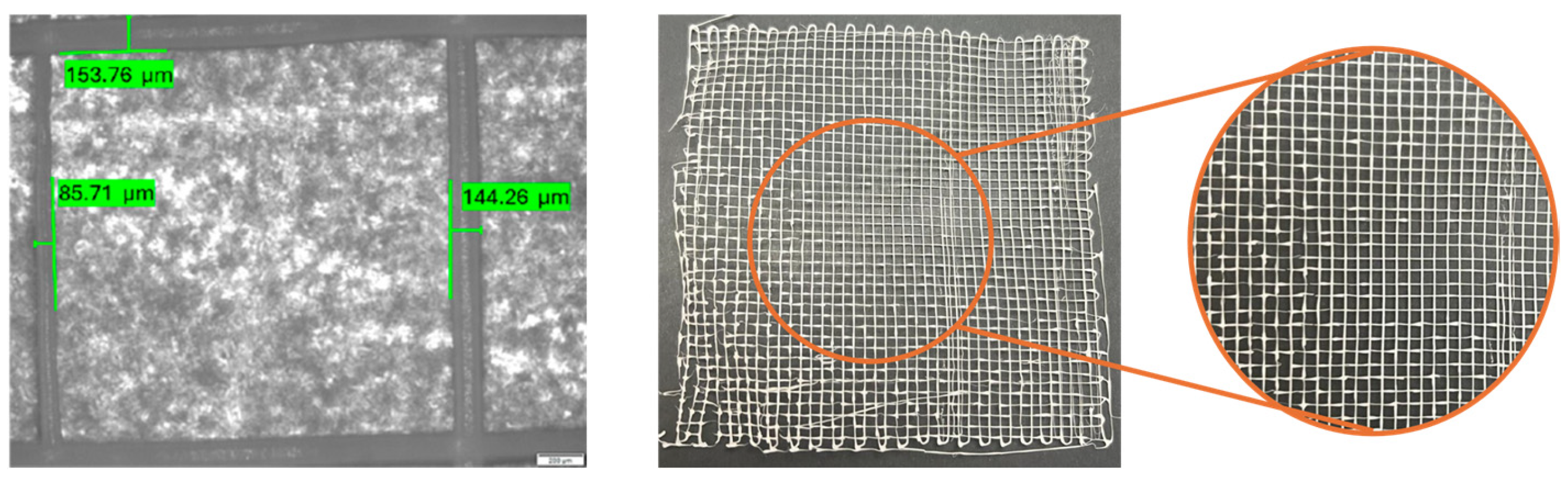
3.1.4. Diameter and Pore Size Evaluation
3.1.5. Final Parameter Adjustments
3.2. Medical-Grade PCL Calibration
3.2.1. Initial Printing Parameters
3.2.2. Diameter Evaluation
3.3. PCL/HT Meshes: Fabrication and Testing
3.3.1. Diameter Evaluation of the PCL/HT Meshes
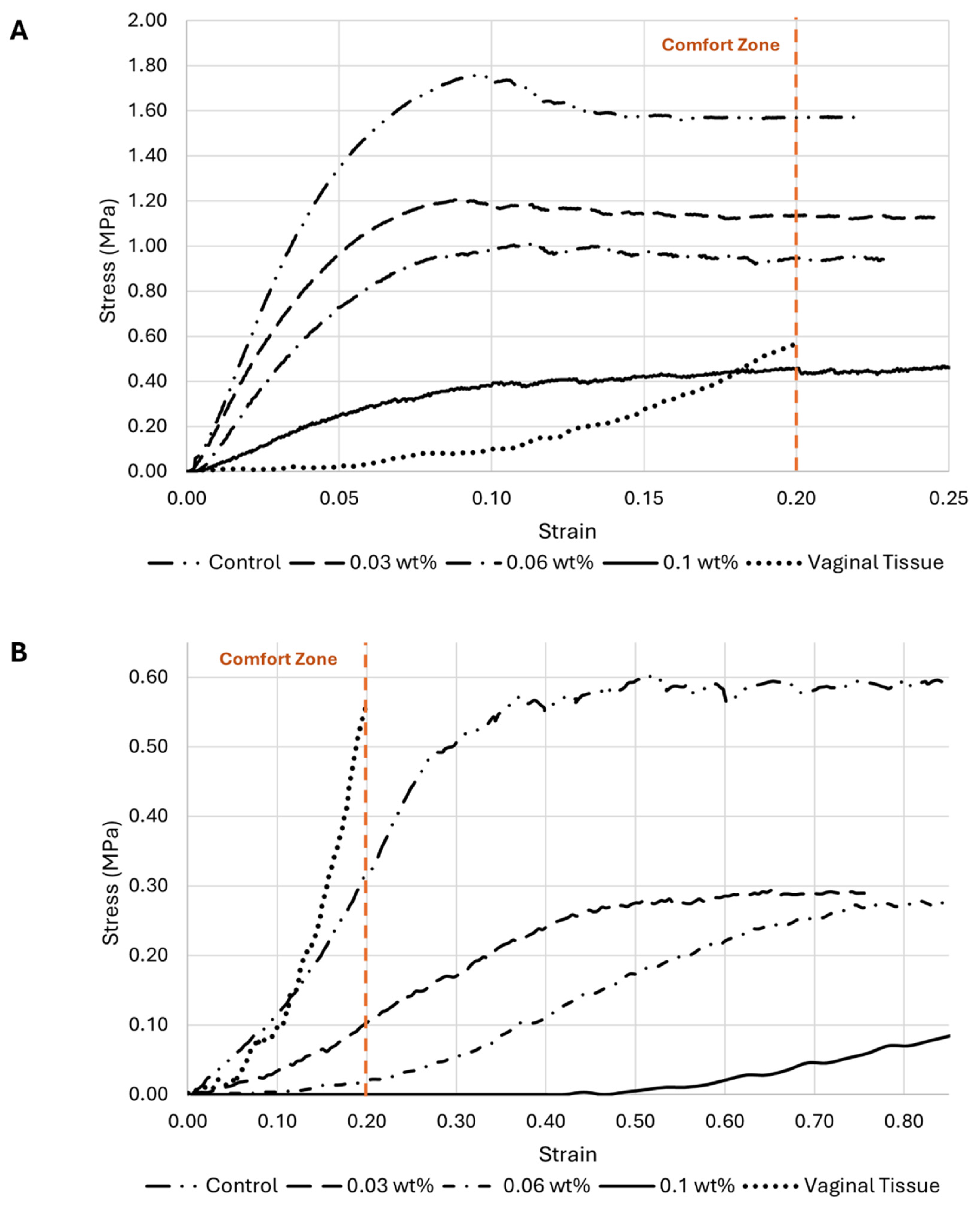
3.3.2. Uniaxial Tensile Testing
- Influence of HT concentration on the meshes’ behavior under load
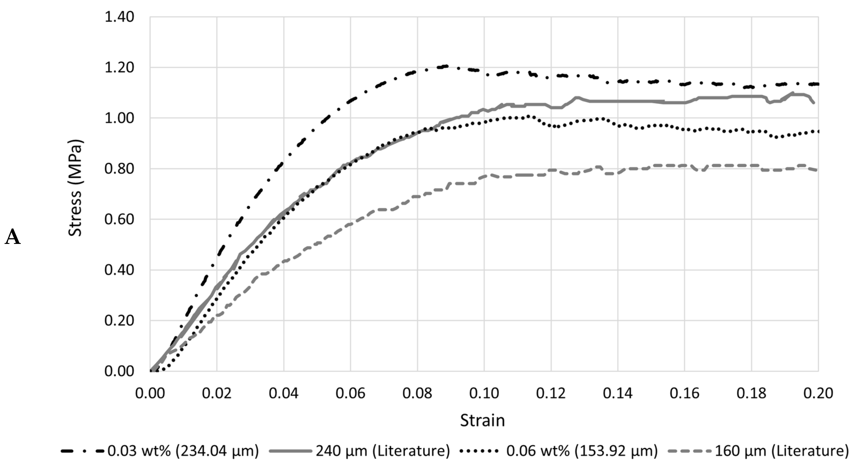
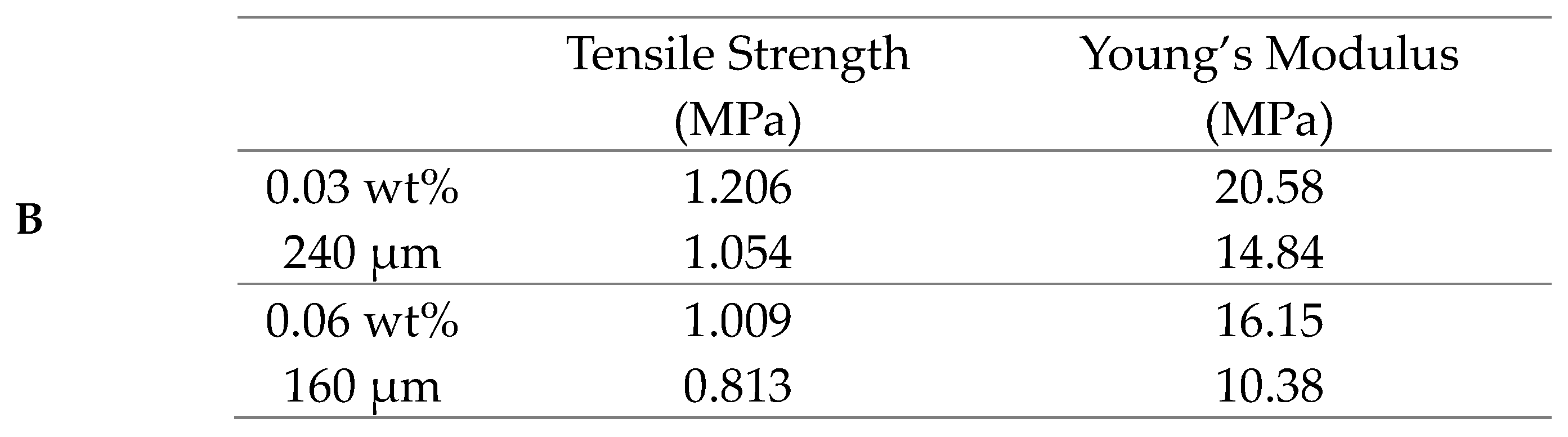
- HT concentration influence on the meshes’ mechanical properties
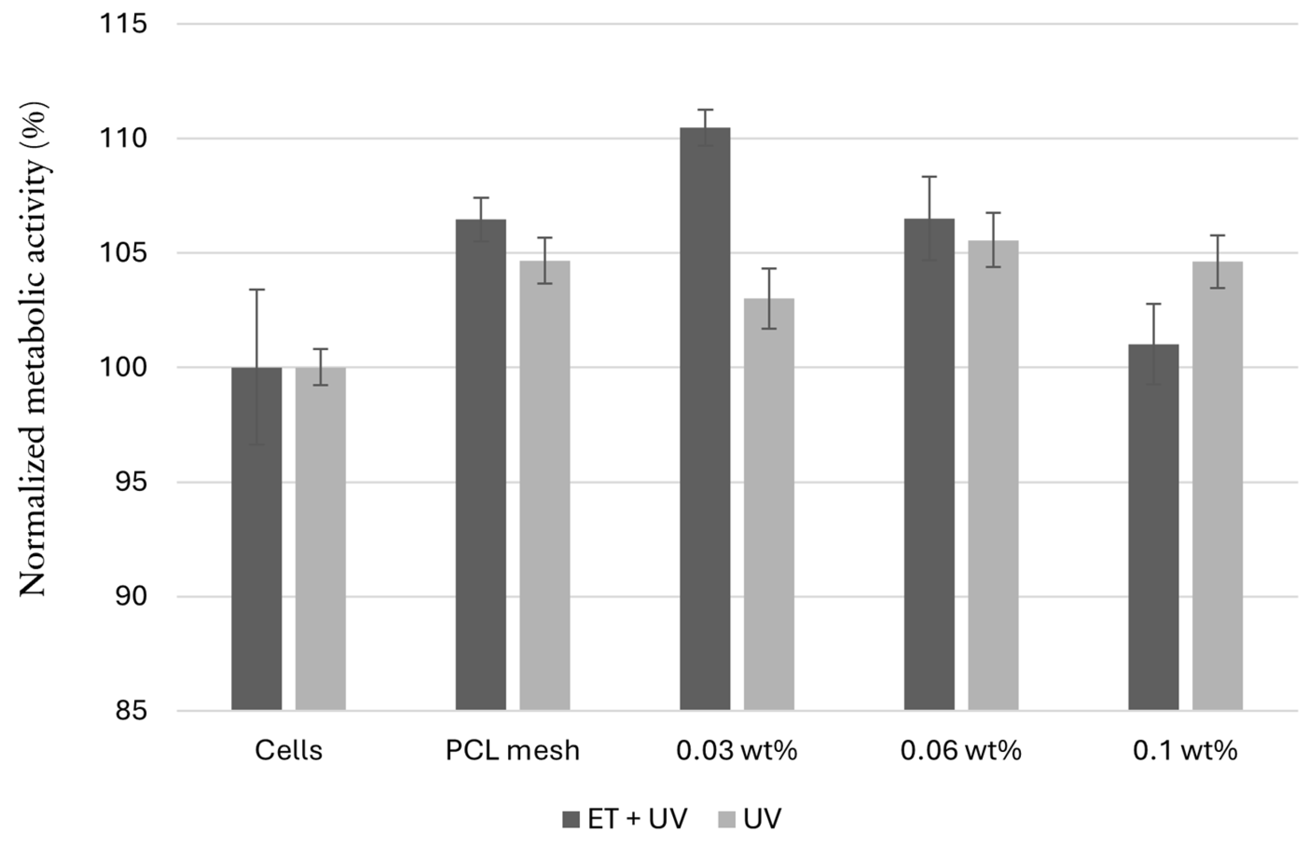
3.3.3. Cytotoxicity Evaluation
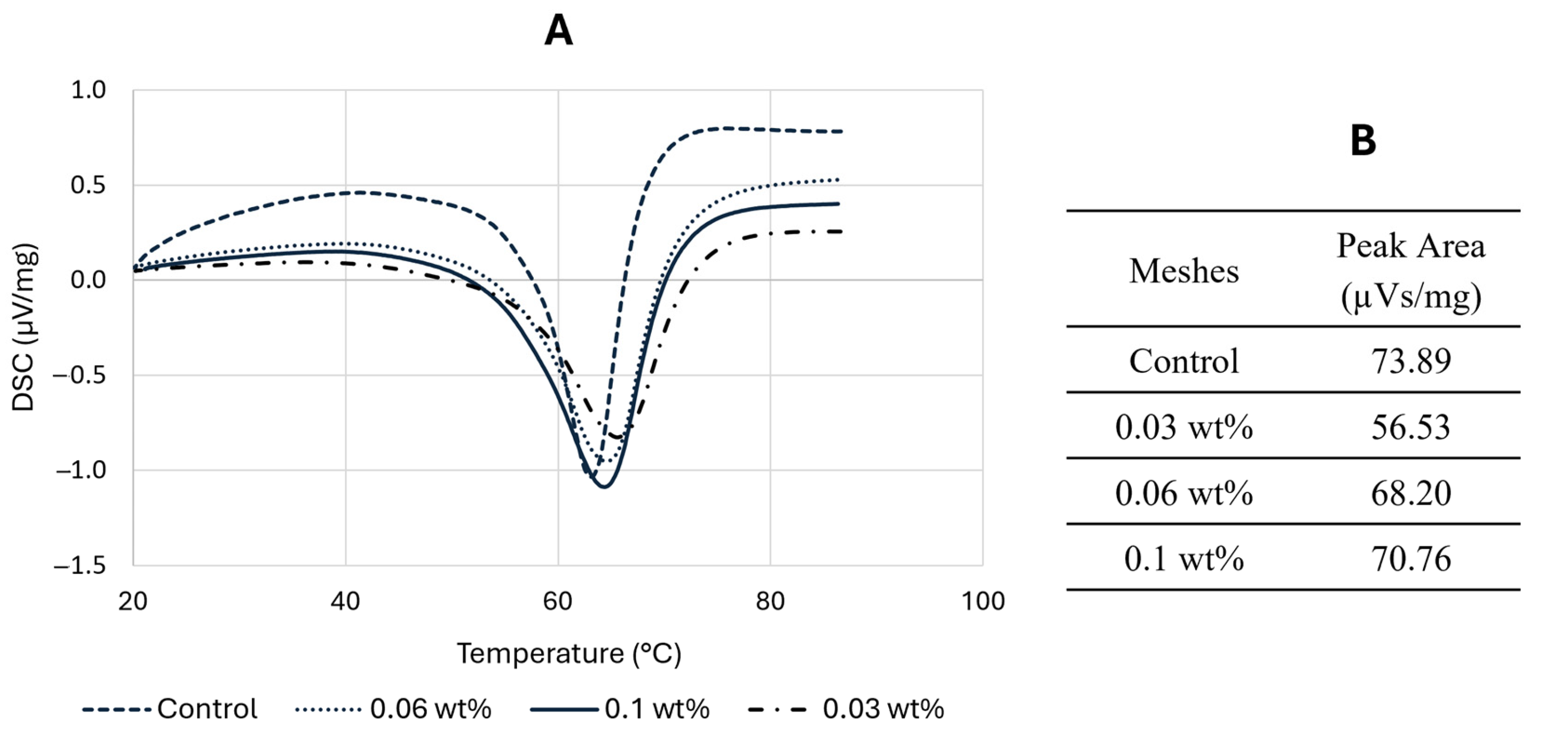
3.4. Differential Scanning Calorimetry
4. Discussion
5. Conclusions
Author Contributions
Funding
Institutional Review Board Statement
Informed Consent Statement
Data Availability Statement
Acknowledgments
Conflicts of Interest
References
- Braga, A.; Serati, M. New Advances in Female Pelvic Floor Dysfunction Management. Medicina 2023, 59, 1010. [Google Scholar] [CrossRef] [PubMed]
- Vaz, M.F.R.R.; Silva, M.E.; Parente, M.; Brandão, S.; Fernandes, A.A. 3D Printing and Development of Computational Models of Biodegradable Meshes for Pelvic Organ Prolapse. Eng. Comput. 2024, 41, 1399–1423. [Google Scholar] [CrossRef]
- Ghanbari, Z.; Ghaemi, M.; Shafiee, A.; Jelodarian, P.; Hosseini, R.S.; Pouyamoghaddam, S.; Montazeri, A. Quality of Life Following Pelvic Organ Prolapse Treatments in Women: A Systematic Review and Meta-Analysis. J. Clin. Med. 2022, 11, 7166. [Google Scholar] [CrossRef] [PubMed]
- Belayneh, T.; Gebeyehu, A.; Adefris, M.; Rortveit, G.; Gjerde, J.L.; Ayele, T.A. Pelvic Organ Prolapse Surgery and Health-Related Quality of Life: A Follow-Up Study. BMC Women’s Health 2021, 21, 99. [Google Scholar] [CrossRef]
- Maher, C.; Feiner, B.; Baessler, K.; Christmann-Schmid, C.; Haya, N.; Marjoribanks, J. Transvaginal Mesh or Grafts Compared with Native Tissue Repair for Vaginal Prolapse. Cochrane Database Syst. Rev. 2016, 2, CD012079. [Google Scholar] [CrossRef]
- Todros, S.; Pavan, P.G.; Natali, A.N. Biomechanical Properties of Synthetic Surgical Meshes for Pelvic Prolapse Repair. J. Mech. Behav. Biomed. Mater. 2016, 55, 271–285. [Google Scholar] [CrossRef]
- Bartuzi, A.; Futyma, K.; Kulik-Rechberger, B.; Rechberger, T. Self-Perceived Quality of Life After Pelvic Organ Prolapse Reconstructive Mesh Surgery: Prospective Study. Eur. J. Obstet. Gynecol. Reprod. Biol. 2013, 169, 108–112. [Google Scholar] [CrossRef]
- Ren, J.; Murray, R.; Wong, C.S.; Qin, J.; Chen, M.; Totsika, M.; Riddell, A.D.; Warwick, A.; Rukin, N.; Woodruff, M.A. Development of 3D Printed Biodegradable Mesh with Antimicrobial Properties for Pelvic Organ Prolapse. Polymers 2022, 14, 763. [Google Scholar] [CrossRef]
- Vaz, M.F.; Martins, J.A.P.; Pinheiro, F.; Ferreira, N.M.; Brandão, S.; Alves, J.L.; Fernandes, A.A.; Parente, M.P.L.; Silva, M.E.T. Medical- and Non-Medical-Grade Polycaprolactone Mesh Printing for Prolapse Repair: Establishment of Melt Electrowriting Prototype Parameters. Appl. Sci. 2024, 14, 9670. [Google Scholar] [CrossRef]
- Mancuso, E.; Downey, C.; Doxford-Hook, E.; Bryant, M.G.; Culmer, P. The Use of Polymeric Meshes for Pelvic Organ Prolapse: Current Concepts, Challenges, and Future Perspectives. J. Biomed. Mater. Res. B. Appl. Biomater. 2020, 108, 771–789. [Google Scholar] [CrossRef]
- Cunha, M.N.B.; Rynkevic, R.; Silva, M.E.T.; Brandão, A.F.M.d.S.; Alves, J.L.; Fernandes, A.A. Melt Electrospinning Writing of Mesh Implants for Pelvic Organ Prolapse Repair. 3D Print. Addit. Manuf. 2022, 9, 10. [Google Scholar] [CrossRef] [PubMed]
- FDA Takes Action to Protect Women’s Health, Orders Manufacturers of Surgical Mesh Intended for Transvaginal Repair of Pelvic Organ Prolapse to Stop Selling All Devices. Available online: https://www.fda.gov/medical-devices/implants-and-prosthetics/urogynecologic-surgical-mesh-implants (accessed on 5 January 2024).
- Arifin, N.; Sudin, I.; Ngadiman, N.H.A.; Ishak, M.S.A. A Comprehensive Review of Biopolymer Fabrication in Additive Manufacturing Processing for 3D-Tissue-Engineering Scaffolds. Polymers 2022, 14, 2119. [Google Scholar] [CrossRef] [PubMed]
- Afghah, F.; Dikyol, C.; Altunbek, M.; Koc, B. Biomimicry in Bio-Manufacturing: Developments in Melt Electrospinning Writing Technology Towards Hybrid Biomanufacturing. Appl. Sci. 2019, 9, 3540. [Google Scholar] [CrossRef]
- Rynkevic, R.; Silva, M.E.T.; Martins, P.; Mascarenhas, T.; Alves, J.; Fernandes, A. Characterisation of Polycaprolactone Scaffolds Made by Melt Electrospinning Writing for Pelvic Organ Prolapse Correction—A Pilot Study. Mater. Today Commun. 2022, 32, 104101. [Google Scholar] [CrossRef]
- Sterk, S.; Silva, M.E.T.; Fernandes, A.A.; Huß, A.; Wittek, A. Development of New Surgical Mesh Geometries with Different Mechanical Properties Using the Design Freedom of 3D Printing. J. Appl. Polym. Sci. 2023, 140, e54611. [Google Scholar] [CrossRef]
- Miller, K.; Hsu, J.E.; Soslowsky, L.J. Materials in Tendon and Ligament Repair. In Comprehensive Biomaterials; Ducheyne, P., Ed.; Elsevier: Oxford, UK, 2011; pp. 257–279. [Google Scholar]
- Xie, Y.; Fang, Q.; Zhao, H.; Li, Y.; Lin, Z.; Chen, J. Effects of Six Processing Parameters on the Size of PCL Fibers Prepared by Melt Electrospinning Writing. Micromachines 2023, 14, 1437. [Google Scholar] [CrossRef]
- Kade, J.C.; Dalton, P.D. Polymers for Melt Electrowriting. Adv. Healthc. Mater. 2021, 10, 2001232. [Google Scholar] [CrossRef]
- Manivasagam, G.; Reddy, A.; Sen, D.; Nayak, S.; Mathew, M.T.; Rajamanikam, A. Dentistry: Restorative and Regenerative Approaches. In Encyclopedia of Biomedical Engineering; Narayan, R., Ed.; Elsevier: Amsterdam, The Netherlands, 2019; pp. 332–347. [Google Scholar]
- Piyasin, P.; Yensano, R.; Pinitsoontorn, S. Size-Controllable Melt-Electrospun Polycaprolactone (PCL) Fibers with a Sodium Chloride Additive. Polymers 2019, 11, 1768. [Google Scholar] [CrossRef]
- Russo Serafini, M.; Mowat, A.; Mustafa, S.; Saifzadeh, S.; Shabab, T.; Bas, O.; O’rourke, N.; Hutmacher, D.W.; Savi, F.M. 3D-Printed Medical-Grade Polycaprolactone (mPCL) Scaffold for the Surgical Treatment of Vaginal Prolapse and Abdominal Hernias. Bioengineering 2023, 10, 1242. [Google Scholar] [CrossRef]
- Chow, W.S.; Tham, W.L. Effects of Antistatic Agent on the Mechanical, Morphological and Antistatic Properties of Polypropylene/Organo-Montmorillonite Nanocomposites. Express Polym. Lett. 2009, 3, 116–125. [Google Scholar] [CrossRef]
- Clariant. Polymer Solutions BU Additives and Adsorbents Hostastat™ FA 38 Antistatic Agent for Plastic Materials. Available online: https://www.clariant.com (accessed on 3 April 2024).
- Sheoran, N.; Boland, B.; Thornton, S.; Bochinski, J.R.; Clarke, L.I. Increasing Ionic Conductivity Within Thermoplastics via Commercial Additives Results in a Dramatic Decrease in Fiber Diameter from Melt Electrospinning. Soft Matter 2021, 17, 9264–9279. [Google Scholar] [CrossRef] [PubMed]
- Omidi, M.; Fatehinya, A.; Farahani, M.; Akbari, Z.; Shahmoradi, S.; Yazdian, F.; Tahriri, M.; Moharamzadeh, K.; Tayebi, L.; Vashaee, D. Characterization of Biomaterials. In Biomaterials for Oral and Dental Tissue Engineering; Tayebi, L., Moharamzadeh, K., Eds.; Elsevier: Amsterdam, The Netherlands, 2017; pp. 97–115. [Google Scholar]
- Rane, A.V.; Kanny, K.; Abitha, V.K.; Thomas, S. Methods for Synthesis of Nanoparticles and Fabrication of Nanocomposites. In Synthesis of Inorganic Nanomaterials; Mohan Bhagyaraj, S., Oluwafemi, O.S., Kalarikkal, N., Thomas, S., Eds.; Elsevier: Amsterdam, The Netherlands, 2018; pp. 121–139. [Google Scholar]
- Horakova, J.; Klicova, M.; Erben, J.; Klapstova, A.; Novotny, V.; Behalek, L.; Chvojka, J. Impact of Various Sterilization and Disinfection Techniques on Electrospun Poly-ϵ-Caprolactone. ACS Omega 2020, 5, 8885–8892. [Google Scholar] [CrossRef] [PubMed]
- Valente, T.A.M.; Silva, D.M.; Gomes, P.S.; Fernandes, M.H.; Santos, J.D.; Sencadas, V. Effect of Sterilization Methods on Electrospun Poly(Lactic Acid) (PLA) Fiber Alignment for Biomedical Applications. ACS Appl. Mater. Interfaces 2016, 8, 3241–3249. [Google Scholar] [CrossRef] [PubMed]
- Gill, P.; Moghadam, T.T.; Ranjbar, B. Differential Scanning Calorimetry Techniques: Applications in Biology and Nanoscience. J. Biomol. Tech. 2010, 21, 167–193. [Google Scholar]
- Roman, S.; Mangir, N.; Bissoli, J.; Chapple, C.R.; MacNeil, S. Biodegradable scaffolds designed to mimic fascia-like properties for the treatment of pelvic organ prolapse and stress urinary incontinence. J. Biomater. Appl. 2016, 30, 1578–1588. [Google Scholar] [CrossRef]
- Backes, E.H.; Harb, S.V.; Beatrice, C.A.G.; Shimomura, K.M.B.; Passador, F.R.; Costa, L.C.; Pessan, L.A. Polycaprolactone Usage in Additive Manufacturing Strategies for Tissue Engineering Applications: A Review. J. Biomed. Mater. Res. B Appl. Biomater. 2022, 110, 1479–1503. [Google Scholar] [CrossRef]
- Arakawa, C.K.; DeForest, C.A. Polymer Design and Development. In Biology and Engineering of Stem Cell Niches; Vishwakarma, A., Karp, J.M., Eds.; Elsevier: San Diego, CA, USA, 2017; pp. 295–314. [Google Scholar]
- Malikmammadov, E.; Tanir, T.E.; Kiziltay, A.; Hasirci, V.; Hasirci, N. PCL and PCL-Based Materials in Biomedical Applications. J. Biomater. Sci. Polym. Ed. 2018, 29, 863–893. [Google Scholar] [CrossRef]
- ISO 1183-1:2025; Plastics—Methods for Determining the Density of Non-Cellular Plastics. Part 1: Immersion Method, Liquid Pycnometer Method and Titration Method. ISO: Geneva, Switzerland, 2025.
- ISO 10993-5:2009; Biological Evaluation of Medical Devices. Part 5: Tests for In Vitro Cytotoxicity. ISO: Geneva, Switzerland, 2009.
- Petiti, J.; Revel, L.; Divieto, C. Standard Operating Procedure to Optimize Resazurin-Based Viability Assays. Biosensors 2024, 14, 156. [Google Scholar] [CrossRef]
- Vaz, M.F.; Martins, J.A.P.; Pinheiro, F.; Ferreira, N.M.; Brandão, S.; Alves, J.L.; Fernandes, A.A.; Parente, M.P.L.; Silva, M.E. Optimizing Melt Electrowriting Prototypes for Printing Non-Medical and Medical Grade Polycaprolactone Meshes in Prolapse Repair. J. Appl. Polym. Sci. 2024, 141, e56408. [Google Scholar] [CrossRef]
- Hochleitner, G.; Jüngst, T.; Brown, T.D.; Hahn, K.; Moseke, C.; Jakob, F.; Dalton, P.D.; Groll, J. Additive manufacturing of scaffolds with sub-micron filaments via melt electrospinning writing. Biofabrication 2015, 7, 035002. [Google Scholar] [CrossRef]
- Zhao, Y.; Liu, Y.; Zhao, H.; Chen, Z. The Synthesis of a Novel Polymer-Type Antistatic Agent and Its Effect on the Properties of Polypropylene. J. Appl. Polym. Sci. 2024, 141, e55589. [Google Scholar] [CrossRef]
- Loewner, S.; Heene, S.; Baroth, T.; Heymann, H.; Cholewa, F.; Blume, H.; Blume, C. Recent Advances in Melt Electrowriting for Tissue Engineering for 3D Printing of Microporous Scaffolds for Tissue Engineering. Front. Bioeng. Biotechnol. 2022, 10, 896719. [Google Scholar] [CrossRef] [PubMed]
- Sun, N.; Yi, C.; Xu, C.; Xu, J.; Ma, M.; Shi, Y.; He, H.; Zhu, Y.; Chen, S.; Wang, X. Fabrication of Permanent Antistatic PMMA Copolymer for Enhanced Antistatic and Mechanical Properties. ACS Appl. Polym. Mater. 2023, 5, 5537–5543. [Google Scholar] [CrossRef]
- Nunes, G. Bioengineered Novel Contraction-Blocking Biomaterials for Skin Tissue Engineering. Master’s Thesis, Faculty of Engineering, University of Porto, Porto, Portugal, 2023. [Google Scholar]
- Łopianiak, I.; Butruk-Raszeja, B.A. Evaluation of Sterilization/Disinfection Methods of Fibrous Polyurethane Scaffolds Designed for Tissue Engineering Applications. Int. J. Mol. Sci. 2020, 21, 8092. [Google Scholar] [CrossRef]

| Temperature (°C) | 160–180–200–220 |
| Collector’s Speed (mm/min) | 500–1000–1200–1400–1800 |
| Voltage (kV) | 2.63–3.03–3.23–3.43–3.63–4.03–4.63 |
| Pore | Fiber Diameter | |||||
|---|---|---|---|---|---|---|
| 260 µm | 200 µm | 160 µm | 260 µm | 200 µm | 160 µm | |
| Sample 1 (µm) Sample 2 (µm) Sample 3 (µm) Sample 4 (µm) | 1483.17 1505.40 1527.60 1494.38 | 1485.11 1562.84 1547.89 1509.51 | 1520.66 1576.94 1583.67 1624.31 | 160.00 144.35 140.27 140.18 | 120.92 113.74 117.39 116.42 | 91.47 94.11 96.67 100.55 |
| Mean (µm) Error (%) | 1502.64 0.18 | 1526.34 1.76 | 1576.40 5.09 | 146.20 43.77 | 117.12 41.44 | 95.70 40.19 |
| Mean error (%) | 2.34 | 41.80 | ||||
| 260 µm | 200 µm | 160 µm | |
|---|---|---|---|
| Sample 1 (µm) Sample 2 (µm) Sample 3 (µm) Sample 4 (µm) | 244.05 242.59 242.01 255.72 | 190.55 189.51 189.33 192.37 | 156.47 157.59 156.53 152.80 |
| Mean (µm) Error (%) | 246.09 5.35 | 190.44 4.78 | 155.85 2.60 |
| Mean error (%) | 4.24 |
| 260 µm | 200 µm | 160 µm | |
|---|---|---|---|
| Sample 1 (µm) Sample 2 (µm) Sample 3 (µm) Sample 4 (µm) | 256.05 239.04 244.30 240.20 | 192.78 190.89 190.08 190.50 | 157.22 159.31 158.31 158.85 |
| Mean (µm) Error (%) | 244.90 5.81 | 191.06 4.47 | 158.42 0.99 |
| Mean error (%) | 3.75 |
| Square Meshes | Sinusoidal Meshes | |||
|---|---|---|---|---|
| Mean Diameter (µm) | Reduction (%) | Mean Diameter (µm) | Reduction (%) | |
| Control (0 wt%) | 281.30 | - | 273.62 | - |
| 0.03 wt% 0.06 wt% 0.1 wt% | 234.04 153.92 98.41 | 16.80 45.28 65.02 | 234.05 165.35 95.07 | 14.46 39.57 65.26 |
| Square | Sinusoidal | Tensile Stress (MPa) | ||
|---|---|---|---|---|
| Printed Fiber Diameter | Printed Fiber Diameter | Square | Sinusoidal | |
| Control | 281.30 | 273.62 | 1.758 | 0.317 |
| 0.03 wt% 0.06 wt% 0.1 wt% | 234.04 153.92 98.41 | 234.05 165.35 95.07 | 1.206 1.009 0.457 | 0.104 0.022 0.004 |
Disclaimer/Publisher’s Note: The statements, opinions and data contained in all publications are solely those of the individual author(s) and contributor(s) and not of MDPI and/or the editor(s). MDPI and/or the editor(s) disclaim responsibility for any injury to people or property resulting from any ideas, methods, instructions or products referred to in the content. |
© 2025 by the authors. Licensee MDPI, Basel, Switzerland. This article is an open access article distributed under the terms and conditions of the Creative Commons Attribution (CC BY) license (https://creativecommons.org/licenses/by/4.0/).
Share and Cite
Cruz, D.; Vaz, F.; Antoniadi, E.; Silva, A.T.; Martins, J.; Pinheiro, F.; Ferreira, N.M.; Bebiano, L.B.; Pereira, R.F.; Fernandes, A.; et al. Antistatic Melt-Electrowritten Biodegradable Mesh Implants for Enhanced Pelvic Organ Prolapse Repair. Appl. Sci. 2025, 15, 7763. https://doi.org/10.3390/app15147763
Cruz D, Vaz F, Antoniadi E, Silva AT, Martins J, Pinheiro F, Ferreira NM, Bebiano LB, Pereira RF, Fernandes A, et al. Antistatic Melt-Electrowritten Biodegradable Mesh Implants for Enhanced Pelvic Organ Prolapse Repair. Applied Sciences. 2025; 15(14):7763. https://doi.org/10.3390/app15147763
Chicago/Turabian StyleCruz, Daniela, Francisca Vaz, Evangelia Antoniadi, Ana Telma Silva, Joana Martins, Fábio Pinheiro, Nuno Miguel Ferreira, Luís B. Bebiano, Rúben F. Pereira, António Fernandes, and et al. 2025. "Antistatic Melt-Electrowritten Biodegradable Mesh Implants for Enhanced Pelvic Organ Prolapse Repair" Applied Sciences 15, no. 14: 7763. https://doi.org/10.3390/app15147763
APA StyleCruz, D., Vaz, F., Antoniadi, E., Silva, A. T., Martins, J., Pinheiro, F., Ferreira, N. M., Bebiano, L. B., Pereira, R. F., Fernandes, A., & Silva, E. (2025). Antistatic Melt-Electrowritten Biodegradable Mesh Implants for Enhanced Pelvic Organ Prolapse Repair. Applied Sciences, 15(14), 7763. https://doi.org/10.3390/app15147763