Article

Research on the Use of Hydro-Pneumatic Shock Absorbers for the Rear Suspension of a Vehicle Cabin

by
Vasile Gheorghe
,
Eliza Chircan
* and
Horatiu Teodorescu Draghicescu
Mechanical Engineering Department, Faculty of Mechanical Engineering, Transilvania University of Brasov, 500036 Braşov, Romania
*
Author to whom correspondence should be addressed.
Appl. Sci. 2025, 15(14), 7759; https://doi.org/10.3390/app15147759
Submission received: 11 June 2025 / Revised: 8 July 2025 / Accepted: 9 July 2025 / Published: 10 July 2025
(This article belongs to the Section Mechanical Engineering)

Abstract

This work explores enhancing rear cabin suspension in vehicles using hydro-pneumatic shock absorbers to maintain the cabin position regardless of load and improve safety by mitigating oscillation impacts. Advanced solutions employ pneumatic elastic elements with automatic adjustment, addressing classic suspension disadvantages like variable cab position and natural frequency with load changes. The experimental analysis of reinforced rubber samples from the air socket material involved tensile testing and scanning electron microscopy. The tensile results showed a clear trend: weak reinforced samples (L, T) were ductile but had a lower strength, while the ones on the reinforcing direction (D_45, D_60) exhibited a significantly increased strength and stiffness, with D_60 being the strongest but least ductile. Stress–strain curves visually confirmed these mechanical behaviors. Crucially, SEM images of fracture surfaces consistently revealed widespread fiber pull out. This indicates that weak interfacial adhesion between the reinforcing fibers and the rubber matrix is a primary limiting factor for the composite′s overall strength.

1. Introduction

This work will focus on identifying the aspects that intervene in improving the rear suspension of a vehicle cabin through the use of hydro-pneumatic shock absorbers. This type of shock absorber helps to improve the position of the cabin relative to both the ground and the chassis, aiming to maintain it regardless of the cabin’s load. Simultaneously, these improvements positively influence the cabin’s protection elements by limiting the impact of oscillations caused by environmental factors and the roadway, thereby increasing traffic safety.
Semi-automatic cabin clamping systems enhance occupant security. This system can be operated by the main hydraulic cabin folding system. Leading vehicle manufacturers are constantly seeking to improve driver and passenger comfort by modernizing cabin suspensions, thus ensuring greater mobility relative to the chassis in the vertical plane. The first generations of cabs had two articulation points at the front, resulting in low elasticity in the vertical plane, and a relatively rigid elastic support (e.g., a leaf spring) at the rear. Cabin folding, in this case, was performed manually, using a pre-stressed torsion bar located on the same axis as the joints. The pre-stressing of the torsion bar reduced the load on the rear support to a value that could be counteracted by manual actuation [1,2,3,4].
New cabs feature a series of significant improvements, such as the introduction of hydraulic folding instead of manual folding. This innovation has led to an increased load on the rear supports, necessitating an appropriate dimensioning of the suspension. The rear suspension of the cabs can be designed with a central point, which requires a yoke fixed to the chassis and a cross member elastically connected to this yoke, using either two coil springs or a leaf spring. Another constructive option is attachment at two lateral points, which eliminates the need for a yoke, thereby creating sufficient space for other uses.
Worldwide, the development and modernization of new suspensions for heavy-duty truck cabs are continuously progressing. The latest solutions are designed to increase the comfort level for both the driver and passengers. The use of pneumatic elastic elements with automatic adjustment, such as replacing a main or secondary spring, offers an advantage in terms of comfort by helping to maintain the cab’s constant position.
Classic suspensions have the disadvantage of not maintaining the constant cab position relative to the chassis, irrespective of the load. This can lead to asymmetric transverse loads and a lack of parallelism between the cabin floor and the plane of the chassis longitudinal members. Another functional disadvantage is that, due to the linear characteristic of the springs, the natural frequency of the suspended mass varies depending on the load.
The disadvantages mentioned above can be eliminated by using pneumatic elastic elements when suspending the cab on the chassis, which may or may not be assisted by classical elastic elements. The pneumatic elements will thus ensure a constant and balanced position of the cab relative to the chassis, regardless of its loading state; a constant frequency of the suspended mass regardless of the cabin loading, thus improving the functional qualities of the cab suspension; and an increase in operational reliability, driver productivity, and safety [4,5].
The constant position of the cab relative to the chassis is achieved through the intervention of a pneumatic suspension adjustment valve, operated by the means of a control lever. The valve is mounted on an element integral to the chassis, and the control lever is mounted to the cab suspension by means of an adjustable tie rod. When an overload occurs, the lever lowers, thus operating an intake valve that allows the passage of compressed air between the pneumatic suspension cushions. Due to this, the body rises until the control lever returns to the horizontal position, at which point the intake valve is blocked, preventing further air intake. When the load decreases, due to the pressure in the suspension, the body rises, implicitly also raising the control lever. This action operates the exhaust valve, which allows air to be discharged from the air cushions, and the body lowers until the lever reaches the horizontal again.
With regard to engine-generated vibrations, they are isolated by the way the engine and gearbox are mounted on metal or cast-iron bearings. Resonant frequencies have been eliminated during studies on other structural elements. Additional vibration isolation is achieved by using independent air suspensions. Depending on the type of cab, two or four air suspension points can be used to dampen a wide range of vibrations and amplitudes generated by road or engine conditions. Thus, an air suspension system provides comfort and stability [6].
Several researchers have focused on finding the properties of shock absorbers, such as Hryciów, Z. [7] who studied issues related to the life cycle of a shock absorber. They established a connection between temperature and damping properties. This led to proving that different environmental conditions can influence component failure, thereby demonstrating that knowing the characteristics of the material and its behavior under certain pressures is important. Additionally, Schickhofer, L. et al. [8] highlighted in their work the need for continuous research on shock absorbers, as several of the known parameters can be altered to induce higher performances. They studied the geometric features of a shock absorber, as well as the material properties in different temperature environments. They manage to create guidelines for the development of future models. Another study was conducted by Stembalski, M. et al. [9], who focused on improving the durability testing of shock absorbers for large vehicles. They examined the connection between the maximum damping force and the displacement speed of the shock absorber piston, as well as the influence of temperature. They showed that the weight of the trailer has a great influence on the shock absorber performance. Liu, Z. et al. [10] identified a problem with the friction heating phenomenon in traditional shock absorbers and designed a variable piston. They analyzed the damping characteristics and the force displacement characteristics and concluded that their design has improved characteristics, excluding the friction problem, therefore improving vehicle operation.
Grzesikiewicz, W. et al. [11] studied the vibration of a vehicle that is equipped with semi-active dampers and the influence of friction generated in them. The purpose of the work was to determine the values of the forces on the dampers at which the criteria function is at its minimum. They showed that the comfort index increased by 51.6% as a result of the form of the criteria function.
Regarding the need to adapt the properties of dampers and finding mathematical solutions, Makowski M. [12] studied a simplified method for controlling the changes that can appear inside dampers used for off-road vehicles. They developed an algorithm that allows the user to select the optimum friction inside the dampers, leading to increased performance. Sun, X. et al. [13] investigated the design of a damper used in vehicle suspensions. They elaborated a model to resolve constraint problems, which was validated by numerical simulations that show its effectiveness. Kayabekir, A.E. et al. [14] studied an algorithm intended to optimize active mass dampers. They highlighted the importance of knowing the mechanical properties of dampers, mass, stiffness, and damping coefficient and managed to create a simulation that showed optimized control over velocity and the limitations of strokes. The method was able to reduce the maximum displacement of the structure by 53.71%. Zhifei, W. et al. [15] proposed a model for a hydraulic shock absorber, by creating a mathematical model and designing its elements. They studied the effects of the accumulator volume, spring stiffness, and damping force on the proposed model, and also conducted a series of experiments on the volume and pre-inflation pressure of the damper to validate the model. Lozoya-Santos J.J. et al. [16] developed a mathematical model used to obtain the characteristics of a classic shock absorber, such as a force–displacement diagram and a velocity–acceleration diagram, which are created using data from general tests, with a precision between 2% and 10%. Jamolov, U. et al. [17] focused their study on developing a finite element design methodology that can be used to develop and optimize the geometry and functions of a damper in vehicles. They considered a multipurpose model that can be used to obtain the electrical, thermal, fluid dynamic properties, and boundary conditions of a damper.
Yaghoubi, S. et al. [18] focused on the importance of the suspension as part of the vehicle and on optimizing the working parameters of a suspension system to reduce vehicle vibrations, using an extra damper. As a result, the maximum vibration was reduced and the whole system was optimized by 32%. Fleps-Dezasse, M et al. [19] highlighted the importance of knowing the parameters for a semi-active damper and the principles implied by its usage. The model they discussed focused on a full vehicle and was compared to a passive controller suspension system. They managed to improve the working parameters, therefore gaining stability without reducing performance. Suciu, B. [20] investigated a controllable colloidal damper used in the automotive industry. They highlighted the importance of knowing the pressurization level and the need for a pressure controlling device. The proposed model had an experimental damping ratio of 153%, which is larger than the required one, so it was concluded that it can be used in real-life applications. Yumei, B. et al. [21] studied the importance of knowing the parameters of a pneumatic spring. The main objective of their work was finding a model for stiffness that considers the influence of the air–diaphragm coupling effect. They added a modification coefficient that quantifies the influence of the air–diaphragm and validated the model having an error of 1.65%. Considering the above-mentioned effect they lowered the error, with the relative stiffness decreasing by 11.05% and 8.26%. Their model helps provide data in a theoretical manner that can help the development of pneumatic spring for more precise usage.
Further studies have focused on the influence of vibrations on the occupant of the vehicle. Shatskyi, I. et al. [22] considered that vibration negatively impacts industrial machinery and personnel. They introduced a dry friction shell shock absorber featuring parallel spring and friction components. Its compact design and excellent damping capabilities, even under high loads, are due to energy dissipation via structural hysteresis within the friction module. A mathematical model predicts its behavior, making it ideal for the mining, oil, gas, and construction industries. Also, Velychkovych, A et al. [23] introduces a novel damper featuring an open, helically cut shell with a deformable filler. The design leverages shell bending and frictional interaction for damping. A numerical model analyzed its performance, confirming that the shell-cut configuration impacts stiffness. This damper is projected for use in the energy and construction sectors, including drilling shock absorbers and earthquake-resistant structures.
All of the mentioned studies helped highlight the importance of a precise model that can provide sufficient data and cover various situations regarding shock absorbers. Knowing the parameters provided by the damper distributors is not enough, as real-world operating conditions are sometimes quite different from the ideal cases considered. As we analyzed previous research, we found it necessary to propose a hydro-pneumatic shock absorber as the elastic element for a cabin suspension system. To analyze and determine the optimum parameters, we examined the loading diagram to derive the loads on the element, as well as the stiffness characteristics and frequencies. These aspects are significant as usually only the driver’s seat has extra damping, while the passenger seat is more subjected to the influence of the driving terrain. Another important factor that influences both the mechanical behavior and the lifespan of the suspension is the material of the air socket. We considered a fiber-reinforced rubber, commonly used in pneumatic suspensions, and analyzed the mechanical behavior of the material. Knowing all the characteristics of the elastic element is important to be able to predict its lifespan, optimal usage environment, and overall performance.
The purpose of this paper is to highlight the advantages of air suspension for vehicle cabins when compared with traditional coil spring suspension systems. The superior performance of air suspension is primarily attributed to its constituent components, with the air chamber being the most critical element. To investigate this, specimens extracted from the wall of an air chamber were subjected to testing. The analysis focused on understanding the structural damage incurred by these specimens and evaluating the impact of internal pressure on the rigidity of the pneumatic element. This research aims to provide a comprehensive understanding of the factors contributing to the enhanced performance and durability of air suspension systems in cabin applications.

2. Materials and Methods

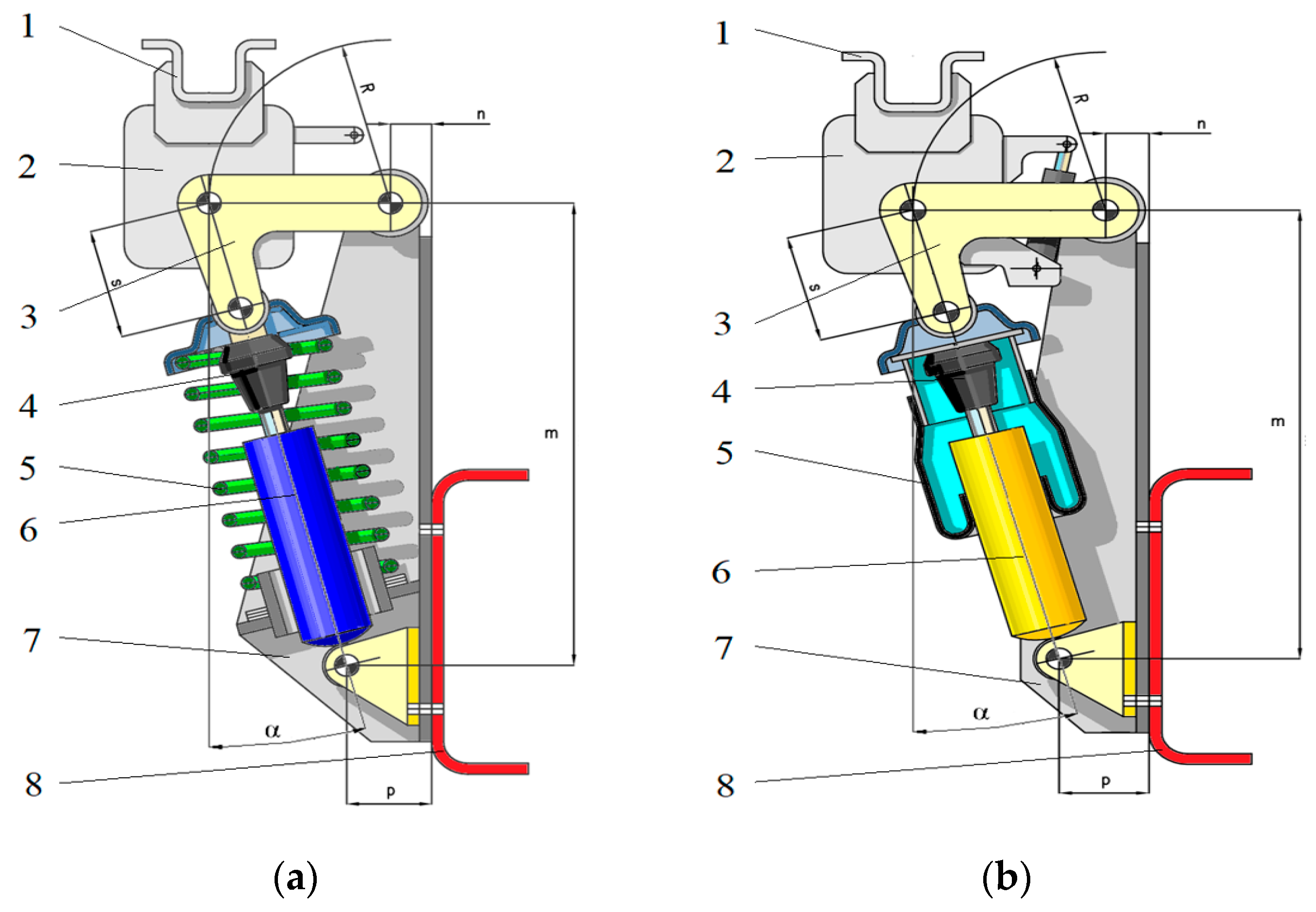
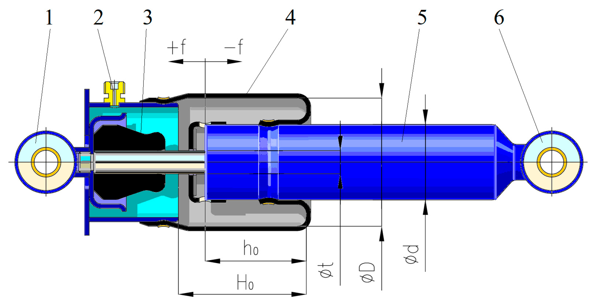
2.1. Geometrical Aspects of the Studied Shock Absorbers

This work explores two constructive variants for a pneumatic rear cabin suspension. The first involves replacing the coil spring with a pneumatic elastic element, consisting of a shock absorber and pneumatic bellows, in the case of the standard suspension with four-point support. Here, the fixing device is rigidly attached to the chassis by means of the hydro-pneumatic shock absorber. The second variant includes two fixing support assemblies on the chassis, onto which the hydro-pneumatic shock absorbers are mounted. These are articulated in the upper part by two upper support assemblies, stiffened by a cross member between them. The two hydraulic locking devices are mounted in the upper supports (Figure 1).
For this study, we used a schematic model of a commonly used helical spring shock absorber as a guideline for positioning and geometry and replaced it with a pneumatic one, as shown in Figure 2.
The dimensions were chosen based on automotive industry requirements, derived from an analysis of helical spring suspension. Table 1 below presents the values considered for the pneumatic suspension.

2.2. Schematic Diagram of the Loading on an Elastic Element

To find the force applied on the rear elastic element, we used a simplified diagram of the loading on the cabin suspension, as presented in Figure 3, including the cabin pivot hinge where we have the force R, the front axle axis between a and b and the simplified elastic element of the cabin suspension. We focused on finding the parameters given by the mass of the cabin, leading to finding the working parameters of the shock absorber that will influence not only the driver’s position, but also have an impact on the passenger, as their seat usually has less damping than the driver’s. We considered two elemental cases, one in which we calculated the force on the elastic rear element considering the loaded cabin, and the other one without any loading, taking into account only the force given by its own weight.
The force (F) on the rear elastic element can be computed using the following equation:
F = Q 2 c o s α
where α represents the shock absorber inclination angle.
The calculation of the stiffness characteristic ( c p ) is performed using the volumetric variations in the air cushion of the pneumatic element. For the numerical determination, the relationship below was used, taking into account the additional air volume (Vs) from the elastic element, as well as the dead volume of air (Vm) formed by the fixed internal volume of the cylinder in position 1. From this, the following volumes are subtracted: the cup 2, the elastic buffer 3, the rod 4, and the stroke limiter 5. Determinations will be conducted for two values of the polytropic coefficient (n), in initial conditions of pressure ( p 0 ) for the empty cabin and a variable displacement ( f ). Another influencing factor is the static height of the variable volume (H0) and the static height of the damping volume (h0). As for the section, we considered the maximum area of the volume variation (A) and the area of the damper (Ad).
c p = n · p 0 V s + V m + A · H 0 A d · h 0 n · A + A d · A 2 V s + V m + A · H 0 A d · h 0 A + A d 2 · f n + 1
The load capacity of the elastic element ( F p ) can be defined using Equation (3):
F p = p 0 V s + V m + A · H 0 A d · h 0 n · A V s + V m + A · H 0 A d · h 0 A + A d 2 · f n
As a safety measure when using elastic elements, one must check the frequency of the natural frequencies. In order to do so, we must know the required pressure in the elastic element to create the necessary lift to support the cabin. We will consider both cases, loaded cabin and own weight, to obtain the range of the stiffness. The stiffness (c) of the elastic element corresponding to these pressures (p) will be:
c = A + A d · A p 2 V m + A · H 0 A d · h 0
The natural frequencies ( n f ) can be computed using Equation (5), considering the mass of the cabin (m):
n f = 30 π c m

2.3. Materials Used for Air Sockets

Several studies were conducted to determine the characteristics of different rubber structures, considering factors such as the manufacturing process, the reinforcing materials, the percentage of recycled elements, and the inclusion of bio-based materials. All the studies were carried out with the desire to create computational models for the considered structures as well as to determine the mechanical properties of the reinforced rubber compounds. Korneev, S.A. et al. [24] studied reinforced rubber elements, simplifying the mathematical model to better describe the connection between force and deformation. This research showed that neglecting the elongation can lead to less reliable data during simulation. In a similar manner, Goncaa, V et al. [25] discussed the characteristics of multilayer elastomeric structures, highlighting the importance of knowing the force–displacement dependence in order to correctly describe the equation of motion of an object protected from low frequency vibrations.
Besides the determination of the properties of known compounds, some research groups have focused on improving the material, such as Wong, D. [26] who suggested a new rubber polymeric composite that can have properties similar to oil-based rubbers. They found that by replacing synthetic fibers with natural ones, they can lower the environmental impact as well as enhance the mechanical properties. Another important factor is the environmental impact of the compound. In this manner, Kabakçi, G.C. et al. [27] studied rubber recycling and its uses. The recycling process reinforces the rubber by adding micro-scale particles, providing a low-cost solution to creating highly resistant reinforced materials, which are suitable for heavy-duty applications.
Studies were conducted on reinforced rubber, as it has a wide range of uses. Anizah, M.A.N. [28] and their research group tried to identify alternative reinforcements for rubber, focusing on the molecular connections between rubber and different fibers, as well as on the mixing and development methods, thereby improving its mechanical properties. Ren, T. et al. [29] demonstrated that reinforcing reclaimed rubber can improve its added value, increasing its thermal and mechanical stability. This is important when using recycled rubbers that include natural components. Pan, S. et al. [30] focused their research on the behavior of a composite rubber buffer reinforced with fiber. Controlling the stiffness of the buffer was possible by knowing the number of layers of reinforcing material. They validated the obtained stiffness model using experimental results, highlighting the need for knowledge regarding different buffer geometry, as rubber composites tend to behave differently depending on the section. An important factor was studied by Tian, X. [31], who conducted research on short fiber-reinforced rubber composites. They proved that during processing the material can suffer problems due to the change in fiber orientation and unstable extrusion quantities. This aspect can influence the material’s wear and lifespan.
All of the previous research suggests that it is necessary to know the exact characteristics of a material to predict its behavior during exploitation. In this manner we considered the air socket material a reinforced rubber used for heavy-duty applications (QWP 190701). We used samples that were cut in four directions (Figure 4 and Figure 5), as the reinforcing mesh inside the rubber has different fiber orientations in each set of samples (Figure 6).
The side images of the samples showing the differences in fiber orientation (Figure 6) were made using a stereo microscope Leica S9 D (Leica, Wetzlar, Germany). This helped us to analyze the positioning of the fiber mesh inside the rubber, proving the necessity of testing samples in four directions as the fibers have different orientations.

3. Methods

3.1. Numerical Considerations for the Hydro-Pneumatic Shock Absorber

In order to determine the parameters of the elastic element, we considered two cases in which we have different polytropic indices ( n = 1 ( i z o t h e r m a l   p r o c e s s e s ) ; 1.3 ). The selected values for the polytropic coefficient are as follows: For n = 1, we have the ideal case, an isothermal process where the temperature of the gas inside the air socket remains constant during usage (compression/extension) and we have perfect heat transfer. The second case, where n = 1.3, signifies the description of a real case scenario, where we have a process that is not perfectly isothermal or adiabatic. We have some heat transfer between the inside gas and the exterior, but we do not maintain a constant temperature. As this study is for a shock absorber, while the air is compressed, its temperature will rise, but some of that heat will dissipate to the shock absorber′s components and the surrounding environment. For n = 1.3, we have a higher rate of increase in stiffness compared with the isothermal case due to heat retention; having a high pressure rise for the same volume change translates to increased stiffness. If the process were perfectly adiabatic (n = 1.4), the stiffness increase would be even more pronounced.
For each case, the deformation of the element(f) was in a range from −0.03 to 0.035 m, a range of additional volumes from 0 to 300 cm3, and an initial pressure in the range of 1 to 6 bar.
Table 2 illustrates the two distinct loading scenarios analyzed in this study. The first case considers the empty vehicle cabin, where the only applied force is attributed to its tare weight. The second scenario involves the cabin loaded to its maximum capacity, corresponding to an approximate mass of 870 kg. These two conditions are important in defining the limits of the operational parameters of the hydro-pneumatic suspension element.

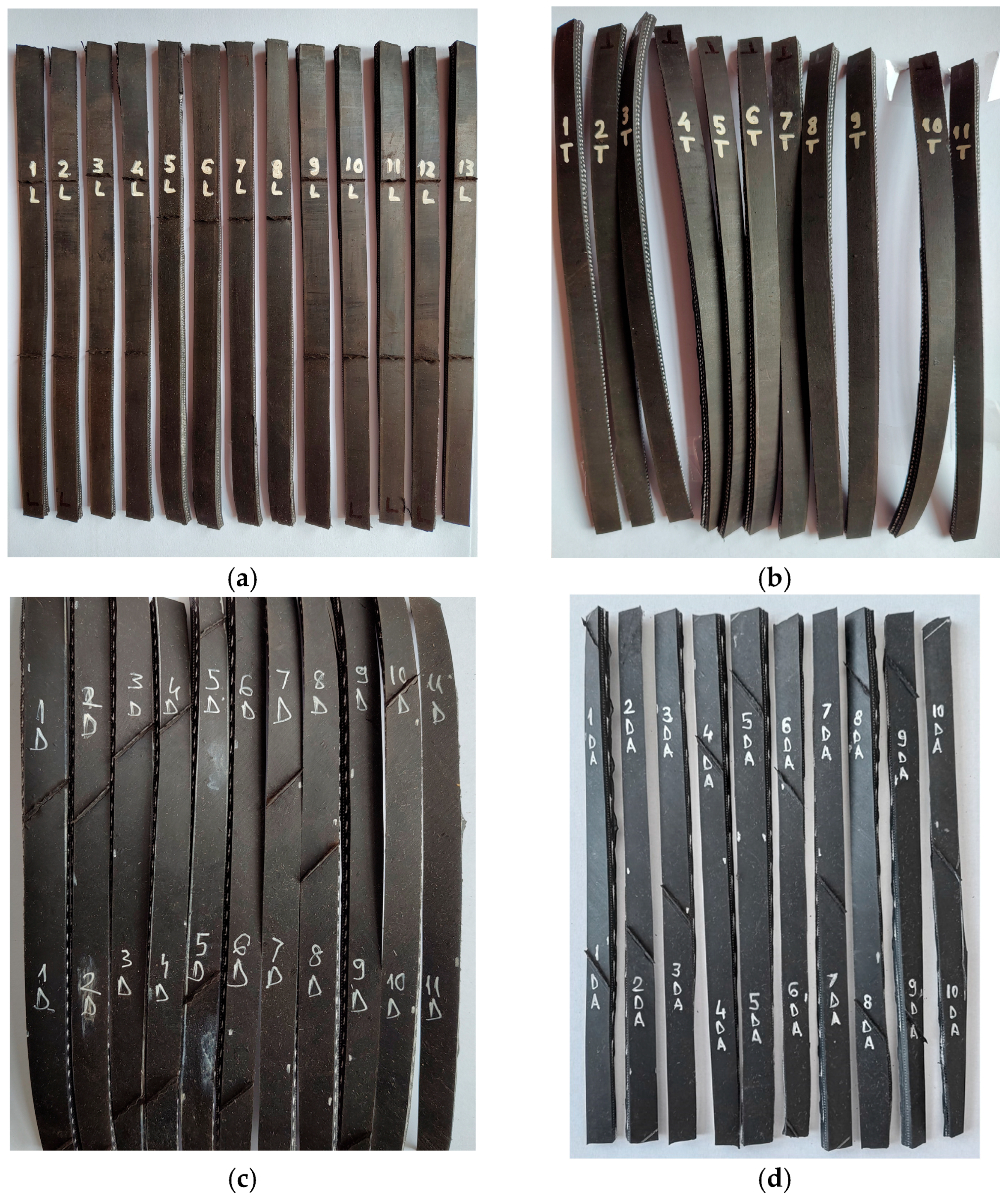
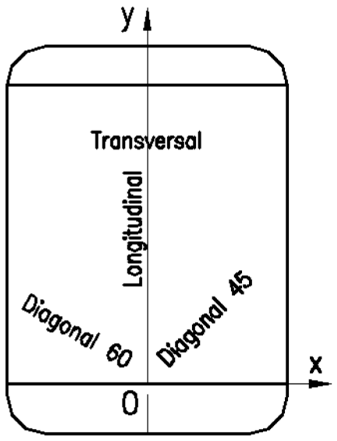
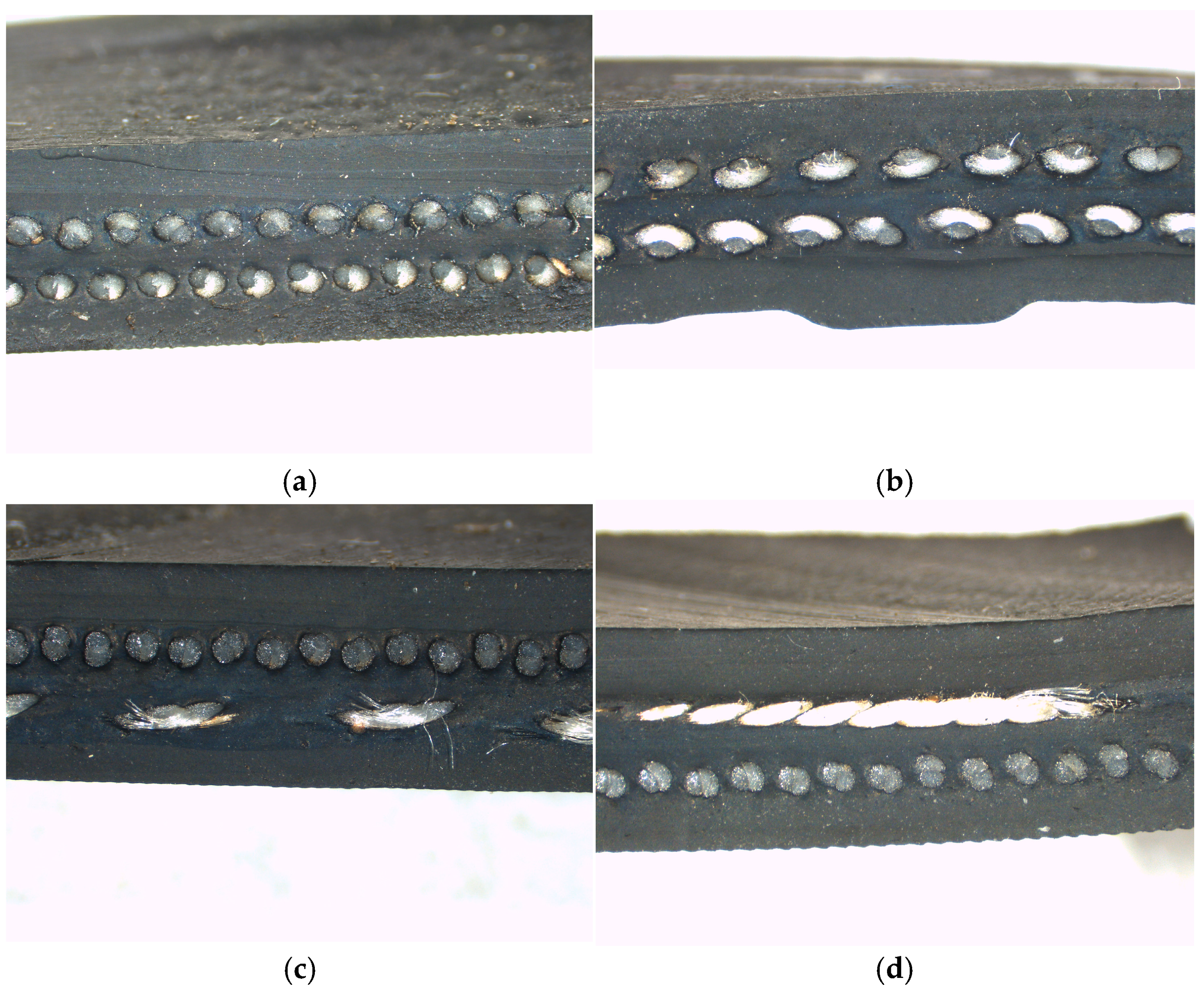
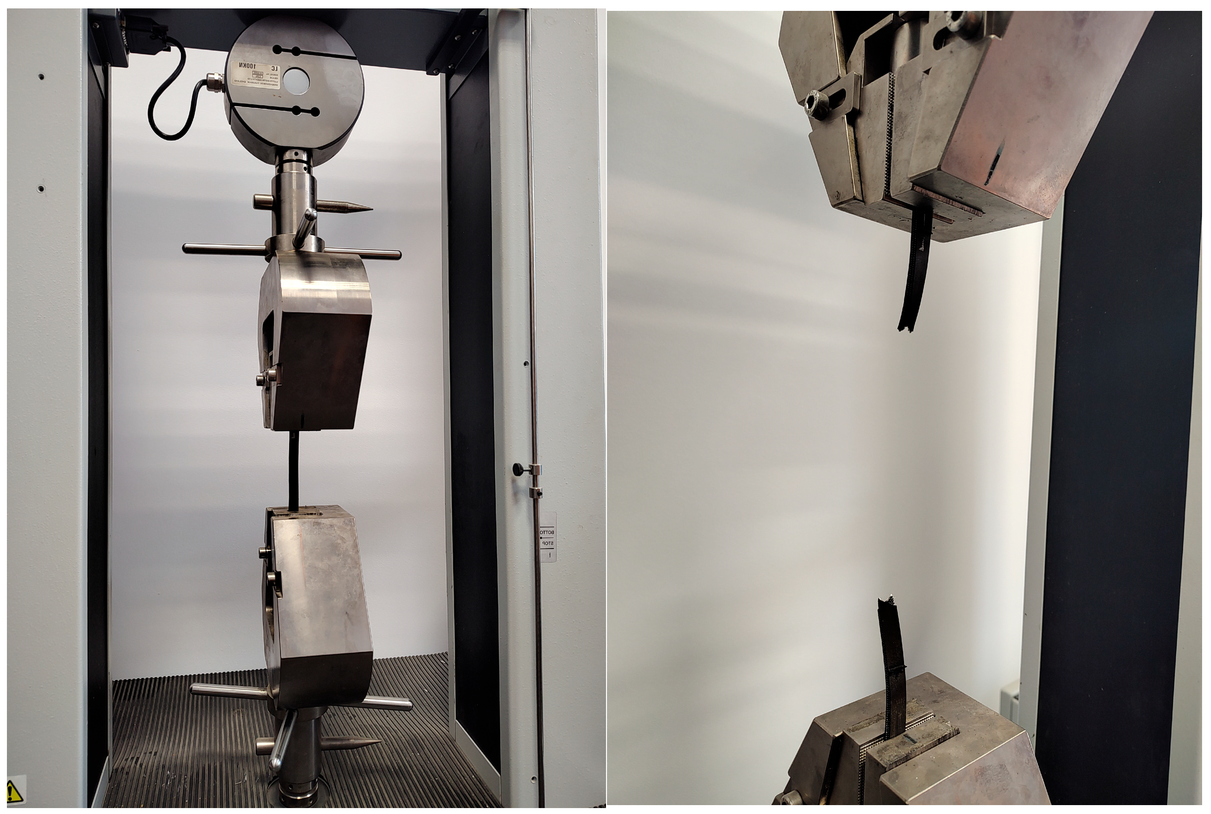
3.2. Experimental Analysis on the Proposed Materials of the Air Socket

The equipment used for testing the specimens is a constant test speed material tensile testing machine according to ISO 5893 [32], consisting of a fixed part, equipped with specimen fixing clamps, and a mobile part, equipped with two fixing clamps and the drive mechanism. The materials testing machine is a LS100Plus (Figure 7) produced by Lloyd’s Instruments, Bognor Regis, UK.
To assess the material′s mechanical properties under tension, a specimen was prepared from the air socket wall and was mounted between the grips of the tensile testing machine. The specimen was subjected to tensile stress until complete rupture (Figure 7). The objective of this test was to quantify critical parameters such as maximum tensile strength, yield strength, and elongation at breaking, which are important for understanding the air chamber′s load-bearing capacity and its resistance to failure under operational stresses (Table 3).

4. Results and Discussion

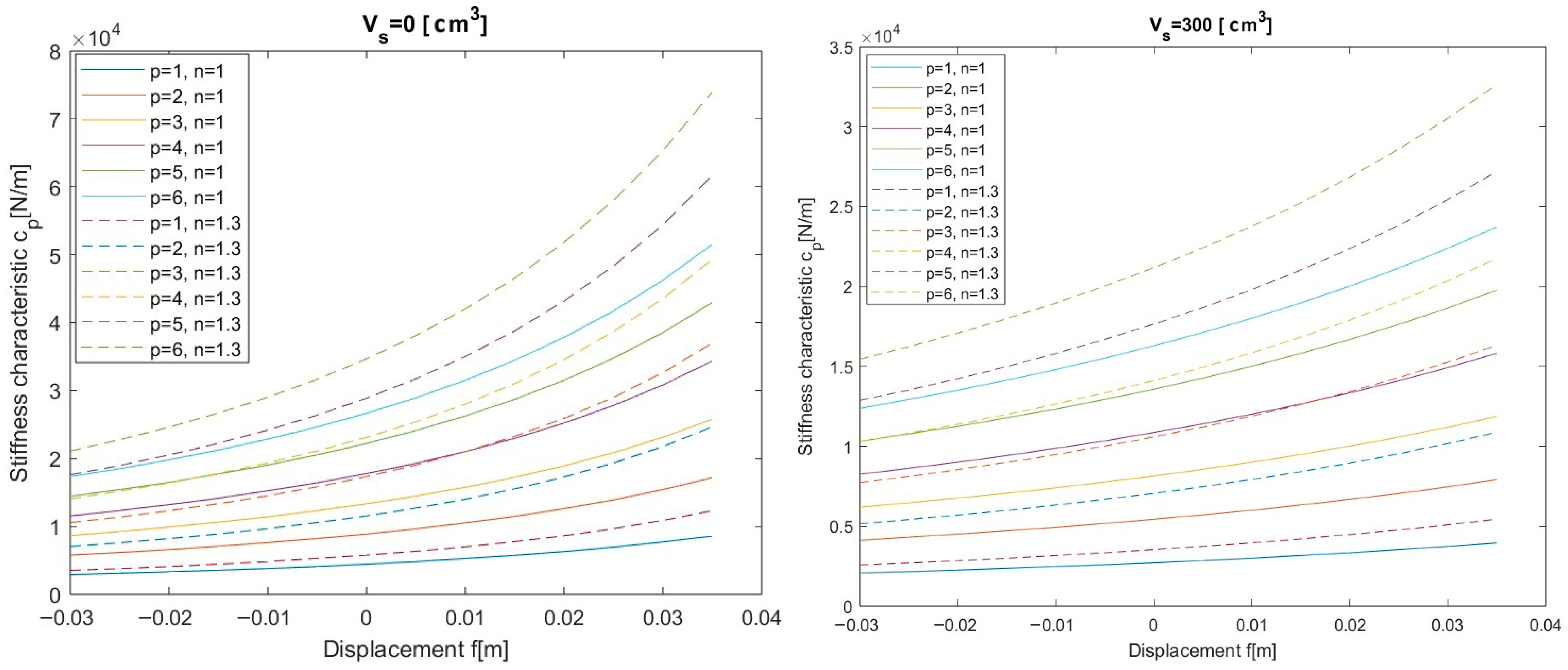
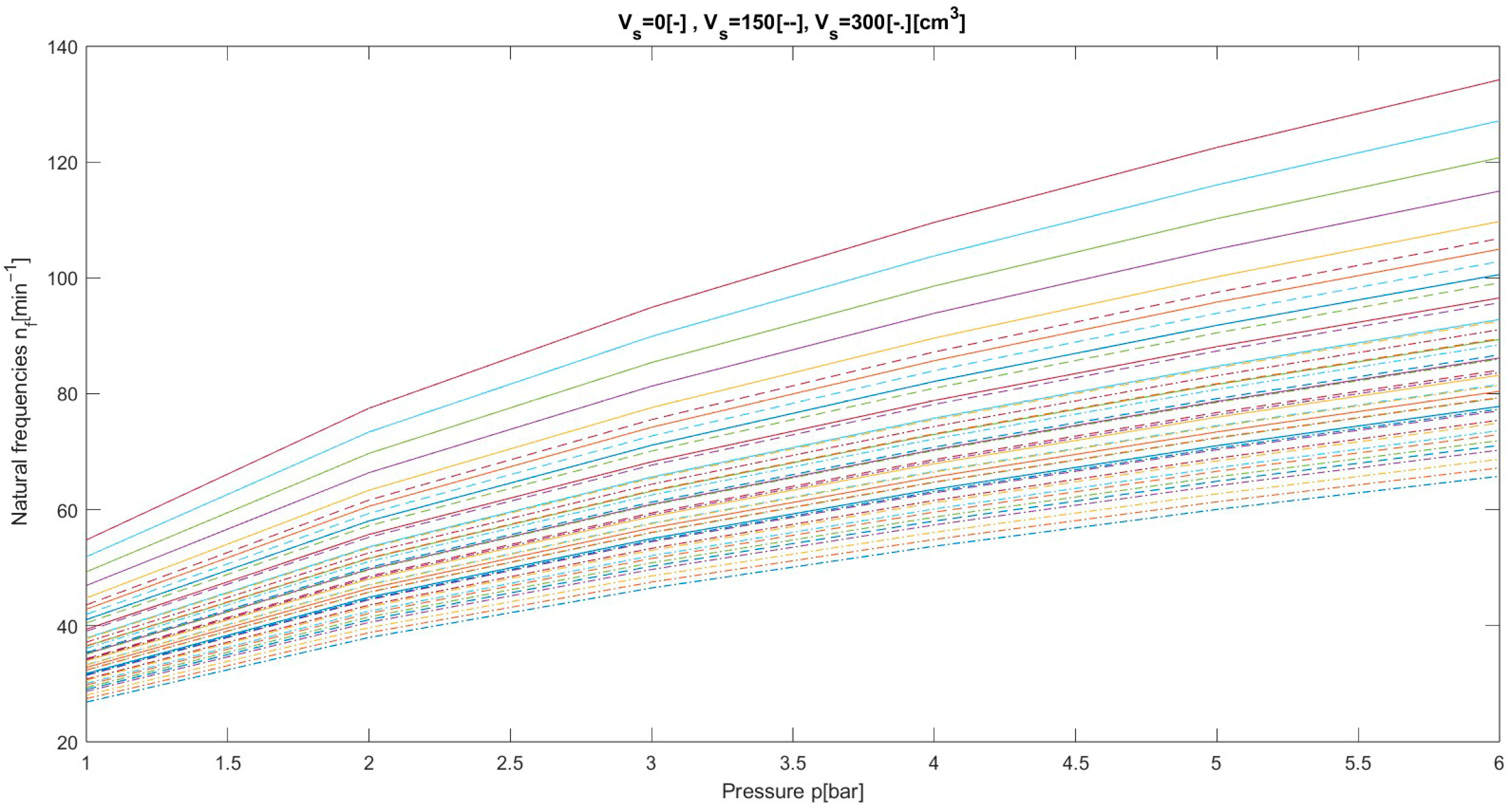
4.1. Numerical Analysis Results of the Hydro-Pneumatic Shock Absorber

The considered elastic element was analyzed for different parameters considering two volumes. The results show that by increasing the volume, the stiffness characteristic decreases, with the element being more elastic. This can be observed in Figure 8. The influence of the polytropic index of the air inside the socket is observed. For the considered value of 1.3, we record a higher rate of increase in stiffness by displacement. This highlights that during isothermal processes (n = 1) the stiffness characteristic does not have a rapid variation.
The load capacity on the elastic element is an important aspect that helps us to identify the range of loads that the element can sustain. As for the results of the computation, the load capacity was considered for a minimum and maximum value of the volume. The maximum displacement of the elastic element provides us with the limit for the load. When we have a deflated state of the air socket, the load is taken by the piston. In this case, we record the maximum load capacity. As we inflate the air socket, the load capacity decreases, as the material of the socket could not sustain as much as the hydraulic element. From here, we see a decrease in the load capacity at the maximum displacement (Figure 9).
The natural frequencies for a range of volumes are presented in Figure 10. The natural frequencies increase as we have a lower air volume in the air socket. This implies that with the increase in stiffness we record a higher frequency. We considered the following masses for the cabin as shown in Table 4.
To highlight the efficiency of the pneumatic element, we also computed the main values of the loads and stiffnesses for a classic elastic helical element, which has been used in the cabin shock absorber (Table 5). We considered the parameters from Table 6 and Table 7 as an equivalence to the proposed elastic element.

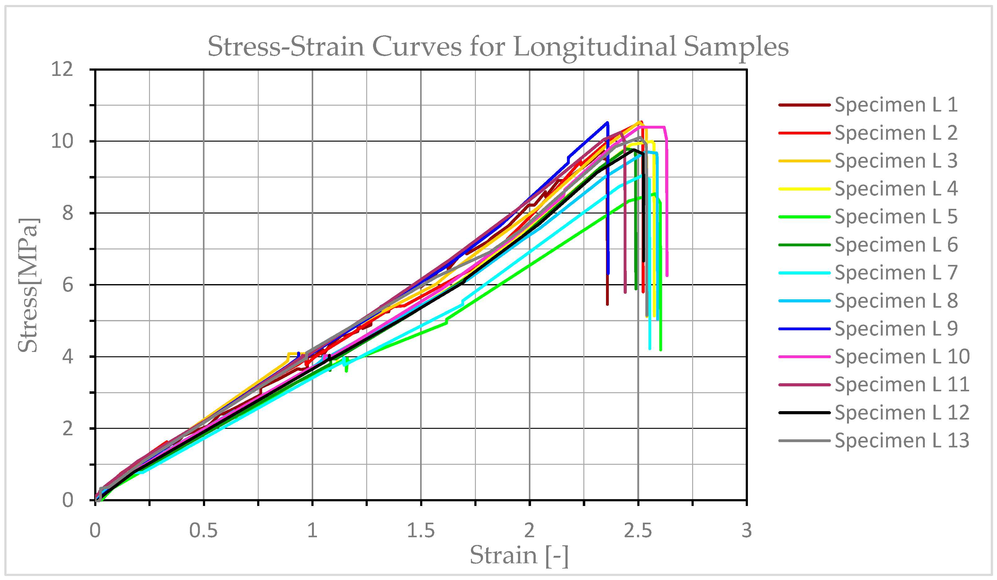
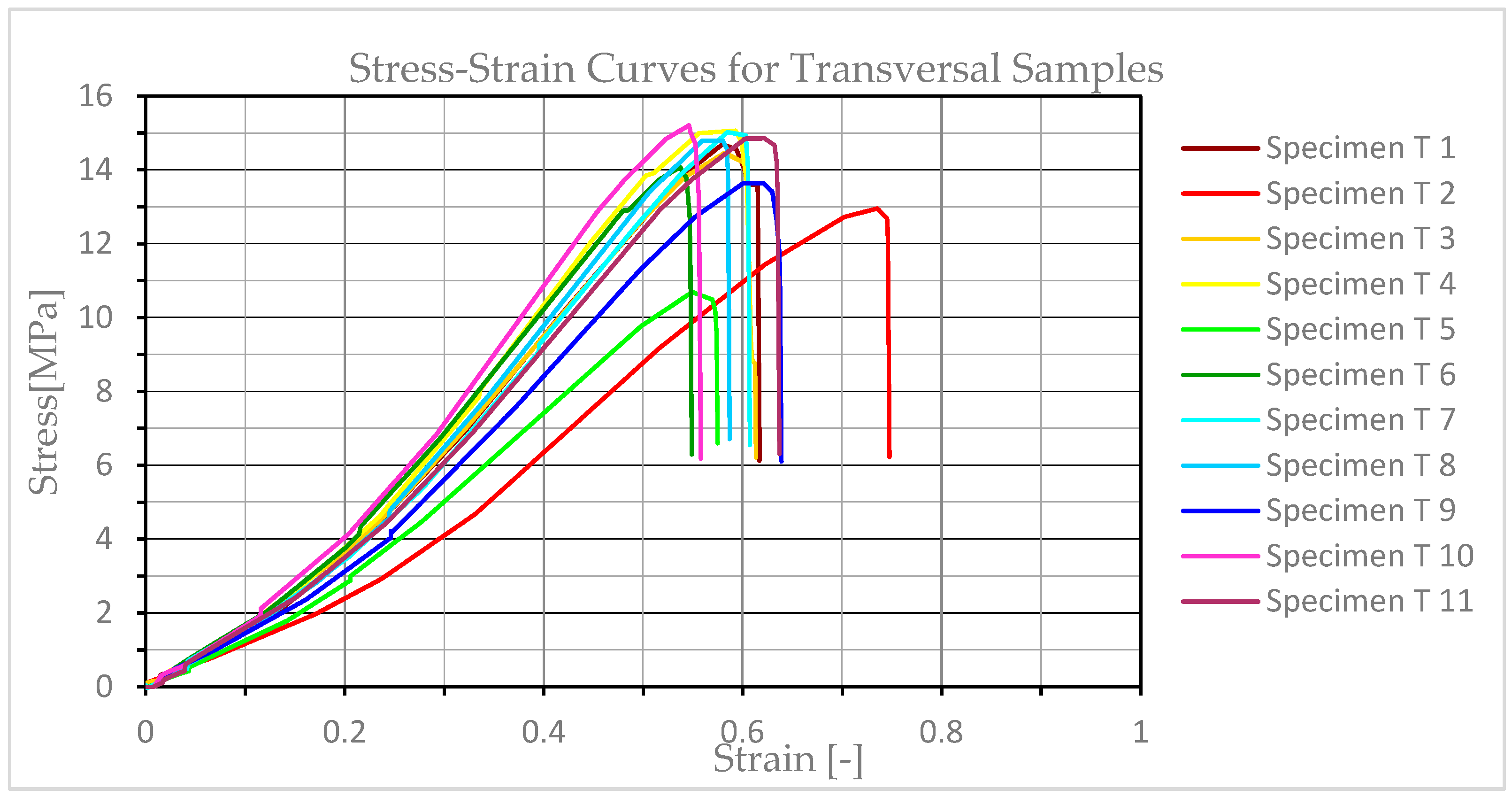
4.2. Experimental Analysis Results on the Proposed Materials of the Air Socket

This section presents the experimental analysis results obtained from the tensile testing of four types of samples of reinforced rubber material designed for shock absorber air sockets. The mechanical properties that were analyzed include tensile strength, stress and strain at break, stiffness, and Young′s modulus, providing crucial insights into the materials′ performance under uniaxial tension (Table 8).
The samples cut at 45° (D_45) and 60° (D_60) exhibit a significantly higher stress at break and tensile strength compared with samples cut on the longitudinal (L) and transversal (T) direction. Notably, the ones cut at 60° show the highest values in these categories, indicating that it has the strongest direction of the cut material among the tested sample directions.
The low Young′s Modulus for the longitudinal cut and the transversal cut samples means that the material will deform more under a given stress in these directions. This might be desirable for applications requiring flexibility or shock absorption.
During the analysis we considered two distinct thermodynamic conditions represented by varying polytropic indices: an isothermal process (n = 1) and a more general case (n = 1.3). This dual approach allows for a comprehensive understanding of how air properties within the shock absorber influence its characteristics under different operational scenarios.
The deformation of the elastic element is constrained within a practical range, specifically from −0.03 to 0.035 m, simulating realistic compression and extension. Furthermore, this study investigates the impact of variable air volumes, ranging from 0 to 300 cubic centimeters, and initial pressures spanning 1 to 6 bar. These ranges are essential for mapping the stiffness and load capacity across diverse operating conditions. To ground the theoretical analysis in real-world application, two crucial cabin load scenarios are considered: an empty cabin with a defined force of 2400 N and a mass of 244.648318 kg, and a loaded cabin demanding a force of 8500 N and a mass of 866.4627931 kg.
The longitudinal samples exhibit high ductility, demonstrating significant elongation before fracture (strains of 2.3–2.5), but with relatively low tensile strength, peaking around 9–10 MPa (Figure 11). Their initial stress–strain response shows a shallow slope, indicating low stiffness, and the curves suggest substantial plastic deformation before fracture. This behavior positions these samples as highly flexible materials, suitable for applications where extensibility and energy absorption are prioritized over high load-bearing capacity, with the reinforcing material having the least influence from all the samples.
The transversal cut samples display a higher tensile strength, reaching peaks between 12 and 16 MPa (Figure 12), making them stronger than the longitudinal cut samples. While less ductile than the longitudinal samples (strains at break around 0.6–0.8), these samples still exhibit considerable elongation. Their initial stiffness is comparable to the previous samples, but many of the specimens show clearer signs of strain hardening, where the material gains strength as it deforms plastically before reaching failure. This suggests that the samples cut in a transversal direction offer a more balanced combination of strength and flexibility, with the reinforcing material of the rubber having more influence than in the previous case.
The samples cut at 45 degrees exhibit significantly steeper initial slopes, indicating a higher stiffness, and achieve peak tensile strengths ranging from approximately 20 to 26 MPa (Figure 13). While their ductility is reduced compared with the previous two directions, as an influence of being cut near the direction of the inner reinforcing material, they still retain some elongation and show clear elastic and plastic deformation regions, often with strain hardening.
The samples cut at 60 degrees represent the top tensile strength among all tested sample directions, reaching peak stresses from around 30 MPa to almost 50 MPa in some instances (Figure 14). This exceptional strength, however, comes with a trade-off as these samples display the lowest ductility, fracturing at strains typically between 0.3 and 0.45. Their stress–strain curves are characterized by very steep initial slopes and a more direct path to fracture after reaching ultimate strength, indicating a more brittle failure mode. In this case, we cut the sample in the direction of the reinforcing material, with the results being influenced by this factor. This shows that the reinforcement material increases the mechanical properties by up to 3.5 times compared with the samples cut in a longitudinal direction.
The methodology′s current application, as presented, is primarily analyzed for two main cases, an empty cabin and a loaded cabin, representing standard vehicle loads. The focus is on improving comfort and stability for typical road and engine vibrations.
A key limitation regarding the behavior and characteristics is the material itself. While capable of carrying a high load, the continuous exposure to forces significantly beyond standard vehicle operations can push the system′s components, including the reinforced rubber air chamber, to their material limits, potentially accelerating wear and failure (e.g., due to weak interfacial adhesion between fibers and rubber as noted in the previous chapters). This material characteristic could significantly impact the air chamber′s durability and performance when subjected to severe and continuous impacts, heavy loads, and high-frequency oscillations.
The SEM images of the L specimens (Figure 15a) in the fracture zone show the orientation of the fiber in the specified direction and its behavior during the tests. As the material is ripped, the breakage appears first in the rubber, then the fibers start delaminating, followed by rupture, as shown in the figure. When subjected to tensile stress, the fibers disengage and slip out of the matrix rather than breaking, suggesting that the full potential of the reinforcement is not being utilized to enhance the composite′s strength. Depending on the fiber orientation, the rupture zone presents changes. As we change the fiber orientation, the behavior of the rupture zone is different from the previous case, as the fiber begins to influence the resistance of the sample.
Figure 15c reveals a more ductile-looking rubber matrix alongside the fiber bundles, suggesting that crack propagation preferentially occurs through the matrix until it encounters the reinforcement, leading to interfacial debonding and fiber rupture. Figure 15d implies a dense cluster of pulled-out and often-tangled fibers, implying a highly reinforced region or a concentration of stress that led to multiple fiber disengagements. The bending and apparent entanglement of these fibers suggest some resistance to pull out, indicating that energy is being absorbed during the fracture process. This happens as the fibers are oriented in the direction of the sample, providing the biggest resistance of all the samples.

5. Conclusions

The use of hydro-pneumatic shock absorbers brings significant improvements by allowing stiffness to be modified according to user requirements.
Hydro-pneumatic shock absorbers offer significant advantages over traditional spring suspensions for vehicle cabins. They maintain a constant cabin position regardless of the load, eliminating issues like uneven loads and non-parallelism. Unlike classic springs, they provide a constant natural frequency, improving suspension performance. These systems also enhance safety and comfort through better oscillation dampening and automatic adjustment, leading to increased operational reliability and driver productivity. Their automatic adjustment feature, controlled by a pneumatic valve, ensures that the cabin remains level. Furthermore, they offer enhanced vibration isolation through independent air suspensions, effectively dampening a wide range of vibrations for improved comfort and stability.
The analyzed pneumatic suspension ensures a constant and balanced position of the cabin relative to the chassis regardless of its loading status. At the same time, a constant frequency of the suspended mass is maintained, regardless of the cabin loading. By using hydro-pneumatic elastic elements in the rear suspension of heavy-duty trucks, comfort in the cabin is improved by reducing the frequency of natural oscillations from 103 to 120 min−1 in the classic suspension to approximately 85 min−1. High oscillations contribute to the tardiness and even nausea of the occupants in the cabin; reducing the values will improve the passengers’ and driver’s overall conditions during usage.
The material deformation recorded by the testing machine at maximum load showed the maximum value in the longitudinal direction of the shock absorber. This is because in this direction, the material has fewer reinforcing fibers than in the other directions.
In terms of mechanical strength, the proposed material for the air socket shows the highest value in the case of specimens cut at an angle of 60° to the longitudinal direction of the shock absorber. This strength is three times higher than that obtained in the longitudinal direction. This is due to the rubber reinforcement fibers of the shock absorber, which are positioned in the direction given by this angle.
Regarding the stiffness of the material, given by Young′s modulus, it shows a maximum in the case of samples taken at an angle of 45° to the longitudinal direction of the hydro-pneumatic shock absorber. This stiffness is 3.5 times higher than that determined in the longitudinal direction of the material.
Changing the orientation of the reinforcement fibers significantly impacts the fatigue endurance and overall performance of the air socket. This is illustrated by the fiber alignment directly influencing the material′s strength, stiffness, and ductility, which in turn dictate its wear and lifespan. Specifically, samples with reinforcement fibers oriented at 45° and 60° (D_45, D_60) exhibit a notably higher strength and stiffness compared with longitudinal and transversal cuts. This increased robustness suggests enhanced fatigue endurance under certain loading conditions.
However, these results are not universally generalizable across all load variables without considering the material′s inherent characteristics. While superior in strength, specimens like D_60, which display maximum stiffness, also demonstrate reduced deformability and a tendency towards more brittle fracture behavior. This is a critical consideration for designers: opting for materials with peak stiffness and strength might lead to a compromise in flexibility and a higher susceptibility to sudden, brittle failures rather than gradual deformation. Therefore, while beneficial for load-bearing capacity, their application must carefully consider the trade-off between ultimate strength and the need for ductility and energy absorption, particularly in dynamic environments where complex load variables and repeated stresses are present.
The experimental analysis demonstrates the effectiveness of reinforcement in tailoring the mechanical properties of rubber materials. The proposed reinforced rubber socket material offers a significantly improved strength and stiffness for the shock absorber, making it suitable for applications demanding a higher load-bearing capacity and dimensional stability.
While hydro-pneumatic suspensions offer significant advantages in adapting to varying loads and providing comfort, their application in highly demanding and aggressive conditions requires a deeper consideration of their inherent material and system limitations, particularly concerning long-term reliability, sealing integrity, and damping performance under sustained extreme and high-frequency loads.

Author Contributions

Conceptualization, E.C. and V.G.; methodology, E.C.; software, E.C. and H.T.D.; validation, V.G., E.C., and H.T.D.; formal analysis, E.C.; investigation, V.G. and H.T.D.; resources, V.G.; data curation, V.G. and E.C.; writing—original draft preparation, E.C.; writing—review and editing, H.T.D.; visualization, V.G.; supervision, V.G. and H.T.D.; project administration, E.C.; funding acquisition, V.G. All authors have read and agreed to the published version of the manuscript.

Funding

This research received no external funding.

Institutional Review Board Statement

Not applicable.

Informed Consent Statement

Not applicable.

Data Availability Statement

The original contributions presented in the study are included in the article. Further inquiries can be directed to the corresponding author.

Acknowledgments

We are very grateful to Transilvania University of Brasov for the given support and for helping us with the APC.

Conflicts of Interest

The authors declare no conflicts of interest.

References

  1. Timbó, R.; Ritto, T.G. Impact of damper seal coefficients uncertainties in rotor dynamics. J. Braz. Soc. Mech. Sci. Eng. 2019, 41, 165. [Google Scholar] [CrossRef]
  2. Yue, S.; Titurus, B.; Li, Z.; Wu, C.; Du, Z. Analysis of liquid spring damper for vertical landing reusable launch vehicle with network-based methodology. Nonlinear Dyn. 2023, 111, 2135–2160. [Google Scholar] [CrossRef]
  3. Knap, L.; Makowski, M.; Siczek, K.; Kubiak, P.; Mrowicki, A. Hydraulic Vehicle Damper Controlled by Piezoelectric Valve. Sensors 2023, 23, 2007. [Google Scholar] [CrossRef] [PubMed]
  4. Wang, J.; Shen, Y.; Du, F.; Li, M.; Yang, X. Topology Optimization Design and Dynamic Performance Analysis of Inerter-Spring-Damper Suspension Based on PowerDriven-Damper Control Strategy. World Electr. Veh. J. 2024, 15, 8. [Google Scholar] [CrossRef]
  5. Yang, X.; Yan, L.; Shen, Y.; Li, H.; Liu, Y. Dynamic performance analysis and parameters perturbation study of inerter–spring–damper suspension for heavy vehicle. J. Low Freq. Noise Vib. Act. Control. 2020, 40, 1335–1350. [Google Scholar] [CrossRef]
  6. Franczyk, B.; Gołdasz, J. Modelling and Experimental Study of a Passive Frequency-Dependent Vehicle Suspension Damper. Acta Mech. Automatica. Sciendo 2024, 18, 409–418. [Google Scholar] [CrossRef]
  7. Hryciów, Z. An Investigation of the Influence of Temperature and Technical Condition on the Hydraulic Shock Absorber Characteristics. Appl. Sci. 2022, 12, 12765. [Google Scholar] [CrossRef]
  8. Schickhofer, L.; Antonopoulos, C.G. Cause–effect relationship between model parameters and damping performance of hydraulic shock absorbers. Int. J. Non–Linear Mech. 2024, 159, 104627. [Google Scholar] [CrossRef]
  9. Stembalski, M.; Czarnuch, A.; Szydłowski, T.; Batory, D. Assessment of the Possibility of Validating the Durability Testing Method for Large-Sized Vehicles Based on Changes in Shock Absorber Characteristics—Preliminary Tests. Appl. Sci. 2024, 14, 127. [Google Scholar] [CrossRef]
  10. Liu, Z.; Jiang, C.; Wen, J. Research on new shock absorber with variable piston volume for automotive. J. Adv. Mech. Des. Syst. Manuf. 2023, 17, JAMDSM0055. [Google Scholar] [CrossRef]
  11. Grzesikiewicz, W.; Makowski, M. Semi-Active System of Vehicle Vibration Damping. Appl. Sci. 2021, 11, 4577. [Google Scholar] [CrossRef]
  12. Makowski, M.; Knap, L. Investigation of an off-road vehicle equipped with magnetorheological dampers. Adv. Mech. Engineering. 2018, 10, 1687814018778222. [Google Scholar] [CrossRef]
  13. Sun, X.; Cai, Y.; Yuan, C.; Chen, L.; Wang, R. Hybrid model predictive control of damping multi-mode switching damper for vehicle suspensions. J. Vibroengineering. 2017, 19, 2910–2930. [Google Scholar] [CrossRef]
  14. Kayabekir, A.E.; Bekda, G.; Nigdeli, S.M.; Geem, Z.W. Optimum Design of PID Controlled Active Tuned Mass Damper via Modified Harmony Search. Appl. Sci. 2020, 10, 2976. [Google Scholar] [CrossRef]
  15. Wu, Z.; Xu, G.; Yang, H.; Li, M.; Wallaschek, J. Analysis of Damping Characteristics of a Hydraulic Shock Absorber. Shock. Vib. 2021, 2021, 8883024. [Google Scholar] [CrossRef]
  16. Lozoya-Santos, J.D.-J.; Tudon-Martinez, J.C.; Morales-Menendez, R.; Sename, O.; Spaggiari, A.; Ramírez-Mendoza, R. A General Modeling Approach for Shock Absorbers: 2 DoF MR Damper Case Study. Front. Mater. 2021, 7, 590328. [Google Scholar] [CrossRef]
  17. Jamolov, U.; Peccini, F.; Maizza, G. Multiphysics Design of an Automotive Regenerative Eddy Current Damper. Energies 2022, 15, 5044. [Google Scholar] [CrossRef]
  18. Yaghoubi, S.; Ghanbarzadeh, A. Modeling and optimization of car suspension system in the presence of magnetorheological damper using Simulink-PSO hybrid technique. Results Eng. 2024, 22, 102065. [Google Scholar] [CrossRef]
  19. Fleps-Dezasse, M.; Brembeck, J. LPV Control of Full-Vehicle Vertical Dynamics using Semi-Active Dampers. IFAC-Pap. 2016, 49, 432–439. [Google Scholar] [CrossRef]
  20. Suciu, B. Experimental investigation on a controllable colloidal damper for vehicle suspension. Mech. Eng. J. 2015, 2, 14-00512. [Google Scholar] [CrossRef]
  21. Bai, Y.; Liu, R.; Wu, J.; Che, J.; Wu, M.; Zhou, R.; Chen, X.; Zeng, L.; Jiang, W. Stiffness model for pneumatic spring with air-diaphragm coupling effect. Precis. Eng. 2024, 91, 728–738. [Google Scholar] [CrossRef]
  22. Shatskyi, I.; Velychkovych, A. Analytical Model of Structural Damping in Friction Module of Shell Shock Absorber Connected to Spring. Shock. Vib. 2023, 2023, 1–17. [Google Scholar] [CrossRef]
  23. Velychkovych, A.; Mykhailiuk, V.; Andrusyak, A. Numerical Model for Studying the Properties of a New Friction Damper Developed Based on the Shell with a Helical Cut. Appl. Mech. 2025, 6, 1. [Google Scholar] [CrossRef]
  24. Korneev, S.A.; Korneev, V.S.; Penkov, I.A. Defining relationships for reinforcing shell elements of a rubber cord composite. Procedia Eng. 2016, 152, 309–313. [Google Scholar] [CrossRef]
  25. Goncaa, V.; Polukoshkob, S.; Boykoc, A. Analytical and Experimental Research of Compressive Stiffness for Laminated Elastomeric Structures. Procedia Eng. 2014, 69, 1388–1396. [Google Scholar] [CrossRef]
  26. Wong, D.; Fabito, G.; Debnath, S.; Anwar, M.; Davies, I.J. A critical review: Recent developments of natural fiber/rubber reinforced polymer composites. Clean. Mater. 2024, 13, 100261. [Google Scholar] [CrossRef]
  27. Kabakçi, G.C.; Aslan, O.; Bayraktar, E. A Review on Analysis of Reinforced Recycled Rubber Composites. J. Compos. Sci. 2022, 6, 225. [Google Scholar] [CrossRef]
  28. Anizah, M.A.N.; Nadras, O.; Hazwan, H.M.; Kannika, S.; Nabil, H. Lignin as Alternative Reinforcing Filler in the Rubber Industry: A Review. Front. Mater. 2020, 6, 329. [Google Scholar] [CrossRef]
  29. Ren, T.; Song, P.; Yang, W.; Formela, K.; Wang, S. Reinforcing and plasticizing effects of reclaimed rubber on the vulcanization and properties of natural rubber. J. Appl. Polym. Sci. 2022, 140, e53580. [Google Scholar] [CrossRef]
  30. Pan, S.; Zhao, M.; Andrawes, B.; Zhao, H.; Li, L. Compressive behavior of cylindrical rubber buffer confined with fiber reinforced polymer. J. Low Freq. Noise Vib. Act. Control. 2020, 39, 470–484. [Google Scholar] [CrossRef]
  31. Tian, X.; Zhu, L.; Li, K.; Wang, K.; Bian, H.; Li, L.; Li, S.; Wang, C. Effect of Gear Pump Extrusion Processing on the Properties of Fiber Reinforced Rubber Composites. Polymers 2020, 12, 985. [Google Scholar] [CrossRef]
  32. ISO 5893:2019; Rubber and Plastics Test Equipment—Tensile, Flexural and Compression Types (Constant Rate of Traverse)—Specification. ISO: Geneva, Switzerland, 2019.
Figure 1. Schematic representation of the helical spring suspension (a) and the pneumatic suspension (b). 1—cabin frame rail; 2—locking mechanisms; 3—lever; 4—buffer; 5a—coil spring; 5b—air chamber; 6—damper; 7—suspension bracket; 8—chassis frame rail; R—lever radius; m, n, p—coordinates of the fixed joints; and α—inclination angle of the assembly.
Applsci 15 07759 g001
Figure 2. Pneumatic shock absorber (1—upper eyelet; 2—air inlet nipple; 3—buffer; 4—air chamber; 5—damper; 6—lower eyelet).
Applsci 15 07759 g002
Figure 3. Simplified diagram of the loading on the vehicle cabin suspension. G0—force due to the mass of the unloaded cabin; Gp—force due to the mass of the loaded cabin; R—reaction force from the cabin′s pivot bearing (R0 is the reaction when the cabin is empty, and ΔR is the reaction caused by the load); Q—load in the damping element (Q0 is the load when the cabin is empty, and ΔQ is the load after it has been loaded); d—distance to the center of mass of the loaded cabin; c—distance to the center of mass of the empty cabin; a, b—distances to the wheel axis.
Applsci 15 07759 g003
Figure 4. Reinforced rubber samples ((a). longitudinal cut; (b). transversal cut; (c). diagonal cut at 45°; (d). diagonal cut at 60°).
Applsci 15 07759 g004
Figure 5. Considered directions for the samples.
Applsci 15 07759 g005
Figure 6. Reinforced rubber samples’ fibers at a side view ((a). longitudinal cut; (b). transversal cut; (c). diagonal cut at 45°; (d). diagonal cut at 60°).
Applsci 15 07759 g006
Figure 7. Experimental setup of the samples inside the testing machine (before and after testing).
Applsci 15 07759 g007
Figure 8. Stiffness variation with displacement.
Applsci 15 07759 g008
Figure 9. Load capacity of the elastic element with displacement.
Applsci 15 07759 g009
Figure 10. Natural frequencies with pressure for a range of volumes (0, 150, and 300 cm3).
Applsci 15 07759 g010
Figure 11. Stress–strain distributions for longitudinal samples.
Applsci 15 07759 g011
Figure 12. Stress–strain distributions for transversal samples.
Applsci 15 07759 g012
Figure 13. Stress–strain distributions for samples with a diagonal cut at 45°.
Applsci 15 07759 g013
Figure 14. Stress–strain distributions for samples with a diagonal cut at 60°.
Applsci 15 07759 g014
Figure 15. SEM images of the rupture zone (a). longitudinal sample; (b). transversal sample; (c). 45° sample; (d). 60° sample.
Applsci 15 07759 g015
Table 1. Dimensions of the pneumatic shock absorber.
ElementValue [mm]
H084
h065
d51
D84
t15.5
Table 2. Considered values for general cases.
F [N]m [kg]
Empty cabin2400244.648318
Loaded cabin8500866.4627931
Table 3. Average values for the 4 samples.
Sample LSample TSample D_45Sample D_60
Median Width10.100 mm10.182 mm10.100 mm10.410 mm
Median Thickness4.4100 mm4.2400 mm4.4100 mm4.4100 mm
Median Area44.541 mm243.172 mm244.541 mm245.908 mm2
Table 4. Considered weights.
m1m2m3m4m5m6m7m8
197.75203.87214.06224.26234.45244.64254.84260.95
Table 5. Compared values for empty and loaded cabin for the pneumatic element.
Empty Cabin
Maximum Mass
Loaded Cabin
Minimum Mass
Pressure on the elastic element p [N/m2]3.5 × 1054.62 × 105
Stiffness of the elastic element c [N/m]15,55020,530
Natural oscillations n [min−1]84.6784.7
Table 6. Helical spring parameters.
Value
Outer diameter [mm]80
Thickness [mm]11.5
Length [mm]270
Coil number10
Active coils8
Table 7. Compared values for empty and loaded cabin for the helical spring.
Empty Cabin
Maximum Mass
Loaded Cabin
Minimum Mass
Pressure on the elastic element p [N/m2]3.5 × 1054.62 × 105
Stiffness of the helical spring c [N/m]31,012.113
Natural oscillations n [min−1]119.57103.57
Table 8. Mean values for the 4 samples.
Sample LSample TSample D_45Sample D_60
Stress at Break [MPa]9.8219.45319.05430.483
Strain at Break [-]2.5080.6130.7640.375
Stiffness [N/m]2489.92456.18800.44402.3
Young’s Modulus [kN]4.1924.26614.8187.192
Load at Maximum Load [MPa]0.4410.6100.9591.542
Stress at Maximum Load [MPa]9.91514.13121.54733.589
Machine Extension at Maximum Load [mm]186.944.56756.99028.108
Strain at Maximum Load [-]2.4910.5930.7590.374
Tensile Strength [MPa]9.91514.13121.54733.589
Elongation at Fracture [mm]188.1745.99457.30728.140
Disclaimer/Publisher’s Note: The statements, opinions and data contained in all publications are solely those of the individual author(s) and contributor(s) and not of MDPI and/or the editor(s). MDPI and/or the editor(s) disclaim responsibility for any injury to people or property resulting from any ideas, methods, instructions or products referred to in the content.

