Article

The Behavior of Wind Turbines Equipped with Induction Generators and Stator Converters Under Significant Variations in Wind Speed

by
Cristian Paul Chioncel
1,
Gelu-Ovidiu Tirian
2 and
Elisabeta Spunei
1,*
1
Department of Engineering Sciences, Faculty of Engineering, Babes-Bolyai University, 400028 Cluj-Napoca, Romania
2
Faculty of Engineering Hunedoara, Polytechnic University of Timisoara, 300006 Timisoara, Romania
*
Author to whom correspondence should be addressed.
Appl. Sci. 2025, 15(14), 7700; https://doi.org/10.3390/app15147700
Submission received: 3 June 2025 / Revised: 27 June 2025 / Accepted: 8 July 2025 / Published: 9 July 2025

Abstract

This study investigates the performance of medium-power wind turbines (within kilowatt range) in response to substantial fluctuations in wind speed. The wind turbines utilize induction generators that have a short-circuited rotor and are controlled by a power converter within the stator circuit. This configuration facilitates the adjustment of the stator frequency, thereby allowing the desired rotational speed to be achieved and guaranteeing that the turbine operates at the maximum power point (MPP). Specific mathematical models for the turbine and generator have been developed using technical data from an operational wind turbine. The study demonstrated that utilizing a power converter within the stator circuit enhances the turbine’s operation at its maximum power point. A crucial aspect of effective MPP operation is the accurate determination of the relationship between wind speed and the corresponding optimal angular mechanical speed. Precise understanding and implementation of the interdependence among the primary generator parameters—namely power, frequency, current, and power factor—in relation to wind speed is essential for maximizing power generation and achieving grid stability for wind turbines operating in variable wind speed.

1. Introduction

To achieve sustainable development goals, it is essential that green energy constitute an increasing share of gross energy consumption. Consequently, in accordance with the latest European directives, it has been established that by 2023, the proportion of renewable sources in gross energy consumption should be at least 42.5%, with a target of reaching 45% [1]. Figure 1 illustrates the variation in the primary sources contributing to electricity production [2]. The analysis reveals that in the year 2000, the energy generated from solid fuels was 800,340 GWh, whereas in 2023 it decreased to 321,498 GWh, representing 40.17% of the initial value. Concurrently, the share of renewable sources has increased significantly, from 406,997 GWh in 2000 to 1,213,388 GWh in 2023, indicating an approximate growth of 33 times compared to the value in 2000 [2].
Regarding the development of installed capacity in wind power plants across Europe, the period from 2013 to 2022 shows a doubling of the installed power (Figure 2) [3].
Regarding the utilization of renewable energy, several challenges have been identified that are relevant to this study, as noted in [4]:
-
The high cost of the initial investment, particularly in cases where there are no government subsidies for the large-scale implementation of these solutions;
-
The shortage of qualified human resources capable of installing, operating, and maintaining electricity generation systems;
-
The inadequate communication among the parties involved regarding the benefits associated with the implementation of renewable energy generation systems;
-
The low reliability of transport networks, which prevents multiple individuals or legal entities from injecting any power into the grid.
Recently, an increasing trend has been identified regarding the integration of wind systems in the production of electricity [5]. This fact is also determined by the consideration that the amortization period of the investment is an acceptable one. Thus, following new studies, it was established that for a wind farm with a power of 105 MW, investment is amortized in 9.1 years, so this sector is in continuous development due to the benefits brought in the long term [6].
Regarding the integration of wind turbines into electricity production systems, it is essential that this process also ensures the stability of the electricity transport/distribution system. To verify the fulfillment of this requirement, prior simulations are necessary, utilizing dedicated programs to determine the impact of renewable sources on the stationery and dynamic stability of the system [7].
It is well known that wind turbines are designed and selected to operate under specific weather conditions and mechanical stress requirements. During operation, these parameters may vary, leading to the conclusion that a continuous correlation between wind speed and optimal angular mechanical speed is essential for delivering maximum power [8,9,10].
To measure or calculate wind speed, various methods are employed, such as
-
The use of a small power turbine operating at maximum power in free air [11];
-
Reversing the aerodynamic model of the turbine based on the estimated values of the turbine’s torque and rotor speed [12];
-
Estimating the rotor speed of the turbine and its torque, utilizing the inverse aerodynamic model and nonlinear control theory [13].
The operation of wind turbines encounters the issue of unpredictable variability in wind speed, impacting both the output power and the structural stability of the turbine system [14]. To manage the output power and, by extension, the wind turbines at varying wind speeds, different control algorithms and methods are employed, such as
-
The implementation of an advanced torque controller, which relies on an efficient estimation of wind speed, has been shown to enhance the accuracy of wind speed estimation by 2–7% compared to alternative methods [15];
-
The application of a PID controller, with results assessed through performance index parameters in the time domain [16];
-
The use of a controller that, based on the power curve corresponding to various wind speeds, aims to track the optimal power curve identified by the control system [17];
-
The application of modified virtual inertial controllers, which also serve to enhance the damping capacity of power oscillations within the energy system [18];
-
The application of vector control oriented by stator flux, achieving a reduction in the generator’s impact on system stability [19].
In certain instances, various dispatch commands for the wind generator are utilized, enabling control of the generator across different wind speed profiles [20], particularly in systems that also allow energy storage [21].
In the case of isolated networks, relying solely on green energy creates challenges regarding stability and frequency control. Following a simulation analysis of a hybrid installation composed of hydropower units, a pumping station, and a wind farm, it was determined that the implementation of a battery storage system would enhance frequency control and ensure the operational security of the electricity generation system [22,23]. Another challenge that must be considered in the operation of wind turbines involves controlling the speed during sudden discharges, which can lead to the rotor accelerating beyond the established limits [24].
There are situations in which wind farms are utilized for secondary frequency regulation [25]. In such cases, it has been observed that the use of energy for frequency regulation generates significantly higher revenue compared to merely supplying electrical energy [26].
This study addresses several significant issues in wind energy, especially concerning variable wind speeds over time: determining the mathematical model for the turbine and generator based on the technical data of the wind system; computing the values of stator frequency, current, and power factor based on wind speed; based on numerical simulations, the analysis highlights notable differences in wind energy capture, particularly at constant and variable generator power under conditions of significant temporal variations in wind speed.
In contrast to the existing research, this paper places particular emphasis on cases where wind speed fluctuates significantly over time, a topic that has been inadequately addressed in the literature, which predominantly focuses on constant wind speeds. The simulations conducted highlight the effects of temporal variations in wind speed.
The primary objectives pursued in this work are
-
Presentation of the current state of research concerning the behavior of wind turbines under significant variations in wind speed;
-
Determining the potential power output based on the characteristics of the wind turbine and the power curve as a function of angular velocity;
-
Determining the power output of the induction generator and constructing the power characteristic as a function of angular velocity, based on its rated values;
-
Establishing the optimal angular mechanical speed by utilizing the mathematical model of the turbine based on its technical parameters, specifically the wind speed;
-
Determining the maximum value of the power supplied by the wind turbine.
The primary objective is to visualize the essential elements—power, energy, and currents—as they relate to the variable speed of the wind.

2. Properties and Characteristics of the Analyzed Wind Turbine

This paper examines the operation of the wind turbine, WT, which is equipped with a squirrel-cage induction generator, under substantial variations in wind speed [16,22]. The technical characteristics of the turbines are rated power at 10 m/s—55 kW, wind speed—2.5 m/s to 25 m/s, survival wind speed—59.5 m/s, no of blades—3, diameter of rotor—20 m; swept area—314 m, and tower height—18 m [27]. We consider that the wind speed varies within the range of (0 to 120) km/h. It is known that at low wind speeds, specifically below 3 m/s, wind turbines remain stationary, with a rotational speed of zero [8,26]. They become operational at speeds exceeding 3 m/s, and within the range of (3 to 10) km/h, they operate at maximum power points (MPPs) (Figure 3) [28]. In certain studies, an asynchronous generator equipped with a dual AC-DC-AC power converter has been analyzed, which, through its control methodology, enables the maximization of power output across a wide range of wind speeds [29].
The turbine’s power, WT, depends on the wind speed, V, and the MAS, ω, whereas the power of the electric generator, EG, is influenced by the stator voltage, US, along with the mechanical angular speed, ω. Additionally, it is essential to consider the altitude at which the turbines are installed, as a lower air density results in a decrease in the power output [30].
For the purpose of analysis, technical data pertaining to a 55 kW wind turbine was examined [31]. The power characteristics of the turbine at two wind speeds, V1 = 3 m/s and V2 = 10 m/s, are illustrated in Figure 3.
The fluctuation in wind speed, represented within these parameters, is highlighted in green within the operational zone. The turbine’s maximum power characteristic, PWT-MAX(ω), intersects the maximum power points, MPP 1, at a wind speed of V1 = 3 m/s, and MPP 2, at a wind speed of V2 = 10 m/s.
For the analyzed case, the power characteristic at V1 = 3 m/s is defined by the relationship
P W T 1 ω , 3 = 19182 3 ω 1.3877 10 2 e 57.63 3 ω 3 3   [ W ]
and for V2 = 10 m/s by the relationship
P W T 2 ω , 10 = 19182 10 ω 1.3877 10 2 e 57.63 10 ω 10 3   [ W ]
The maximum power characteristic developed by the turbine is
P W T M A X ω = 1.6744 10 3 ω 3   [ W ]
Fixed-blade wind turbines are protected against strong winds (over 25 m/s) by several methods, because they do not have the ability to adjust the pitch of the blades to reduce speed.
When wind speeds exceed 10 m/s, to prevent damage to the structural integrity of the wind system, it is necessary to engage the turbine rotor’s braking mechanism using a furling system. This allows the turbine to automatically turn away from the direction of strong winds, thereby reducing the force exerted on the blades and limiting the generator’s rotational speed. As the turbine blades are no longer perpendicular to the airflow, the rotational speed decreases and the load on the generator diminishes, thereby safeguarding the turbine from overloading. In the absence of a furling system, a mechanical brake will be employed at high wind speeds to keep the rotor’s speed within the nominal operating limits [12,13].
Consequently, the speed of the generator must be adjusted in accordance with the ratio 1/3.3.
To achieve optimal energy performance within this speed range, adjustments are made to the voltage and frequency at the generator by utilizing power converters [32,33] that are connected to the stator of induction generators with a short-circuited rotor or to the rotor of induction generators equipped with slip rings.
Induction generators with a wound rotor can utilize two converters: one for the stator winding and the other for the rotor winding. In this scenario, the costs are high, so, generally, this solution is not justified.
In [34,35], the analysis of induction generators with a wound rotor was conducted in detail, utilizing a power converter in the rotor circuit to achieve the MPP operation of the turbine. In this scenario, the voltage at the rings exceeds twice the nominal stator voltage at a wind speed of 10 m/s, thus making the specially designed rotor more expensive compared to the conventional type.
The variations in wind speed cause the wind turbine to operate in a dynamic regime and at variable speeds [8,26]. Given that the process is dynamic, the equation for kinetic momentum is utilized, in the form [20,21,22].
J d ω d t = M W T M E G
where ω is the MAS at the generator shaft, J is the equivalent inertia moment, /dt is the MAS time derivative, MWT is the moment provided by WT, relative to the EG shaft, and MEG is the electromagnetic moment at the EG shaft.
Multiplying with ω, we obtain the power equation [36,37].
J d ω d t ω = P W T P E G
where PWT is the useful power provided by WT, referenced to the electric generator shaft, and PEG is the electromagnetic power of EG at the shaft.
The WT functions at the convergence of the power characteristics of the EG and that of the turbine, PWT(ω).
The maximum wind energy is harnessed when the wind turbine (WT) functions at its maximum power points (MPPs) [38]. In this regard, the power characteristic of the electric generator, PEG(ω), has to correspond to the maximum power curve generated by the turbines (Figure 3) [39].
The electric generator power characteristic, PEG(ω), is influenced by the power values related from the stator via the power converter located between the generator and the grid.
In the simulations provided, the rotational speeds of wind turbines that are fitted with a gearbox are related to the shaft of the electric generator. The rotational speeds at the turbine shaft are kT times less; kT represents the transmission multiplication ratio.

3. Mathematical Models of the Induction Generator and the Three-Blade Horizontal Axis Turbine

The control of wind systems relies on mathematical models of the induction generator and the turbine [40].

3.1. The Mathematical Model of the Induction Generator

An analysis was conducted on wind turbines equipped with induction generators with the following nominal data [1,31,41]:
  • The moment of inertia, J = 0.34 kgm2;
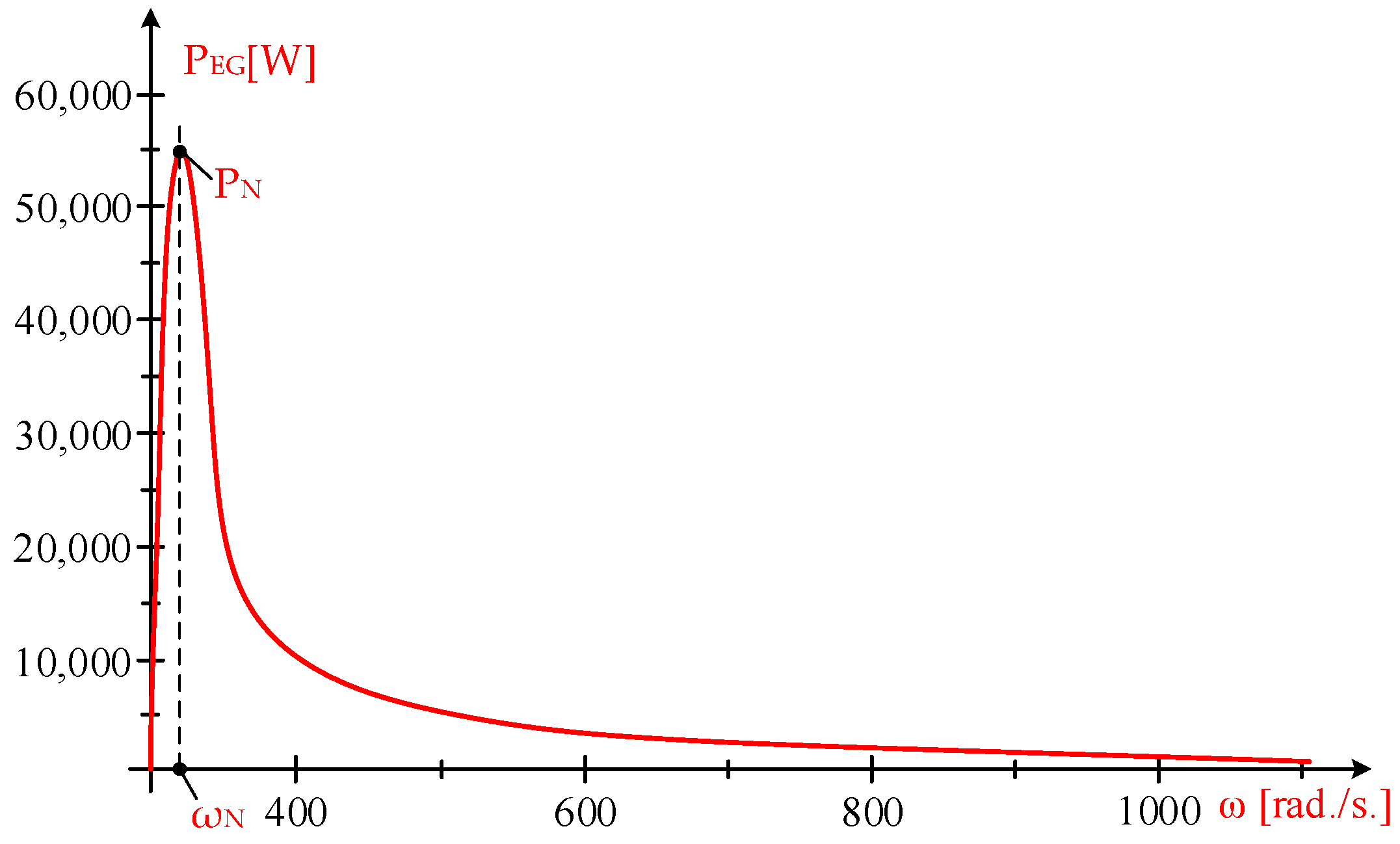
  • The nominal power PN = PEG = 55 kW;
  • The rated voltage UN = 400 V;
  • The nominal current IN = 98 A;
  • The number of poles 2p1 = 2;
  • Nominal speed nN = 2940 rpm;
  • The nominal sliding sN = 0.02.
The parameters of the generator are established based on the nominal data, at the nominal frequency fN = 50 Hz. The nominal operating slip is
s N = n 1 n n 1 = 3000 2940 3000 = 0.02
n1 represents the rotational speed of the spinning field, while n is the rotor’s rotational speed.
The rotor resistance, denoted as RR, is determined from the power balance equation
s N P N = 3 R R I N 2
or
0.02 55000 = 3 R R 98 2
with the solution RR = 3.8179 × 10⁻² Ω.
The stator resistance is equal to the rotor resistance: RS = RR = 3.8179 × 10⁻² Ω.
The short-circuit reactance, Xsc, is derived from the nominal current, IN, as follows:
I N = 230 3.8179 10 2 + 3.8179 10 2 0.02 2 + X s c 2
or
98 = 230 3.8179 10 2 + 3.8179 10 2 0.02 2 + X s c 2
with the solution Xsc = 1.31 Ω.
The rotor parameters RR and XR are minimized at the stator in the following manner:
R R = k 2 R R R E A L ; R R = k 2 X R R E A L
where k = N1/N2, N1 is the number of turns per phase in the stator, and N2 is the number of turns per phase in the rotor.
The magnetizing reactance, XM, is regarded as significantly larger in comparison to the short-circuit reactance.
With these parameters of the generator, the stator current IS and rotor current IR at the stator voltage US are
I S ¯ = U S ¯ R S + R R s + j X s c = U S ¯ 3.8179 10 2 + 3.8179 10 2 s + j 1.31
I R ¯ = I S ¯
The electromagnetic power of the induction generator at the shaft is
P E G = 3 U S 2 R R s R S + R R s 2 + 1.31 2 = 3 230 2 3.8179 10 2 s 3.8179 10 2 + 3.8179 10 2 s 2 + 1.31 2
By substituting the slip s with the mechanical angular velocity ω, the following results are obtained:
s = ω 1 ω ω 1 = 1 ω ω 1 = 1 ω 314 = 1 3.1847 10 3 ω
The power characteristic of the induction generator, PEG, is obtained:
P E G ω = 3 230 2 3.8179 10 2 s 3.8179 10 2 + 3.8179 10 2 s 2 + 1.31 2 = 3 230 2 3.8179 10 2 1 3.1847 10 3 ω 3.8179 10 2 + 3.8179 10 2 1 3.1847 10 3 ω 2 + 1.31 2
at UN = 230 V, f = 50 Hz. Figure 4 illustrates the generator’s power characteristics.
The coordinates of the generator’s nominal power point are nominal power PN = PEG = 55 kW. The nominal slip is
s N = ω 1 ω N ω 1 = 314 ω N 314 = 0.02
the nominal mechanical angular velocity is ωN = 320.28 rad./s.
The converter positioned between the generator and the grid facilitates the operation of the wind system across a broad range of speeds, frequencies, and voltages by maintaining a constant steady-state flow:
U f 1 = 230 50 = 4.6   V / Hz
The ratio of voltage to frequency serves as an indicator of the saturation level of the magnetic core. Utilizing the expression for generator power
P E G = 3 U S 2 R R s R S + R R s 2 + 1.31 2
and replacing s with
s = ω 1 ω ω 1 = 1 ω 2 π f = 1 0.15915 f ω
we obtain
P E G = 3 U S 2 R R s R S + R R s 2 + 1.31 2 = 3 4.6 2 3.8179 10 2 1 0.15915 f ω 3.8179 10 2 + 3.8179 10 2 1 0.15915 f ω 2 f 2 + 1.31 50 2
Which is visible in Figure 5.
As will be demonstrated through the mathematical model of the turbine, the wind system operates optimally at the mechanical angular velocity ωOPTIM = 32.026 V, which is determined by the wind speed, V.
The power of the generator, under constant stator flux, is influenced by the mechanical angular velocity, ω, and the stator frequency [40]:
P E G ω , f = 3 4.6 2 3.8179 10 2 1 0.15915 f ω 3.8179 10 2 + 3.8179 10 2 1 0.15915 f ω 2 f 2 + 1.31 50 2

3.2. The Mathematical Model of the Turbine

The mathematical model of the turbine is established using the technical data from [31]. The power output provided by the WT is calculated using the relationship outlined in [8,16]:
P W T ω , V , β = a V ω b e c V ω V 3
where the values of the parameters a, b, and c can be determined from the technical data of the turbine as follows:
(1)
The maximum power value is achieved at ωOPTIM by setting the derivative of power to zero:
d P W T d ω = d d ω a V ω b e c V ω V 3 = V 4 a ω 3 e V c ω ω V c + b c ω = 0
or
ω V c + b c ω = 0
or
ω O P T I M = c 1 + b c V = k V
Given that the wind speed V is 10 m/s, the optimal mechanical angular velocity, ωOPTIM, is equal to the nominal mechanical angular velocity of the generator [37]:
ω O P T I M = ω N = 320.28   [ rad . / s . ]
achieving
ω O P T I M V = 320.28 10 = 32.028
or
c 1 + b c = 32.028
This is the initial equation of the system involving the unknowns a, b, and c.
(2)
The maximum power value of the WT corresponds to the optimal MAS, ωOPTIM:
V ω O P T I M = 1 + b c c
and it is
P W T M A X V = a 1 + b c c b e c 1 + b c c V 3 = a c e 1 c b V 3
following that
k p = a c e 1 c b
At a wind speed of V = 10 m/s, the maximum power output WT is PWT-MAX = 55,000 W, which indicates that the proportionality factor kp is determined as follows:
k p = P W T M A X V 3 = 55000 10 3 = 55
and the second equation is obtained:
a c e 1 c b = 55
These two equations are fundamental in establishing the mathematical model of the wind turbine (MM-WT) and in determining the coordinates of the maximum power point (MPP), optimal angular velocity (ωOPTIM), and maximum wind power (PWT-MAX).
For a wide range of WT, the report ωOPTIMMAXIM, [15,42] has the value ωOPTIM/ωMAXIM = 4/9; ωMAXIM represents the maximum mechanical angular velocity during the no-load operation of the wind turbine.
(3)
The value of the ratio ωOPTIM/ωMAXIM leads to Equation (3).
Since the power of the wind turbine is zero when operating under no load
P W T = a V ω b e c V ω V 3 = 0
at MAS
ω = ω M A X I M = V b
By substituting ωMAXIM into the ratio ωOPTIM/ωMAXIM, we obtain
ω O P T I M ω M A X I M = c 1 + b c 1 b = b c 1 + b c
and it results in
4 9 = b c 1 + b c
Thus, the system in the unknowns a, b, and c was obtained:
c 1 + b c = 32.028 a c e 1 c b = 55 4 9 = b c 1 + b c
with the solution a = 19,182, b = 1.3877 × 10⁻², and c = 57.65.
The mathematical model of WT was obtained in the form
P W T ω , V = 19182 V ω 1.3877 10 2 e 57.65 V ω V 3   [ W ]
The maximum power point, MPP, is achieved by setting the derivative of power with respect to ω to zero, resulting in the following:
d P W T ω , V d ω = d 19182 V ω 1.3877 10 2 e 57.65 V ω V 3 d ω = 0
or
1.1058 10 13 V 3.4528 10 11 ω = 0
with the solution ωOPTIM = 32.026·V.
The maximum power value of the WT corresponds to the optimal MAS and is
P W T M A X V = 55 V 3
depending on the wind speed:
P W T M A X ω = 55 ω 32.026 3 = 1.6744 10 3 ω 3
or the mechanical angular speed.

4. System Operation in the Optimal Zone: Analysis of Various Dependencies

The adjustment of the frequency and the stator voltage is performed using the converter interposed between the generator and the grid (Figure 6).
By adjusting the frequency, f, and the stator voltage, the optimal mechanical angular speed, ωOPTIM, is achieved based on wind speed.
The generator power at constant stator flux is defined in (22) and in the steady state it is equal to the turbine power defined in (40). It results in
19182 V ω 1.3877 10 2 e 57.65 V ω V 3 = 3 4.6 2 3.8179 10 2 1 0.15915 f ω 3.8179 10 2 + 3.8179 10 2 1 0.15915 f ω 2 f 2 + 1.31 50 2
Given that the inertia of the converter situated between the generator and the grid is significantly lower than the mechanical inertia of the turbine, it can be assumed that the stator frequency, f, is achieved without any dead time.

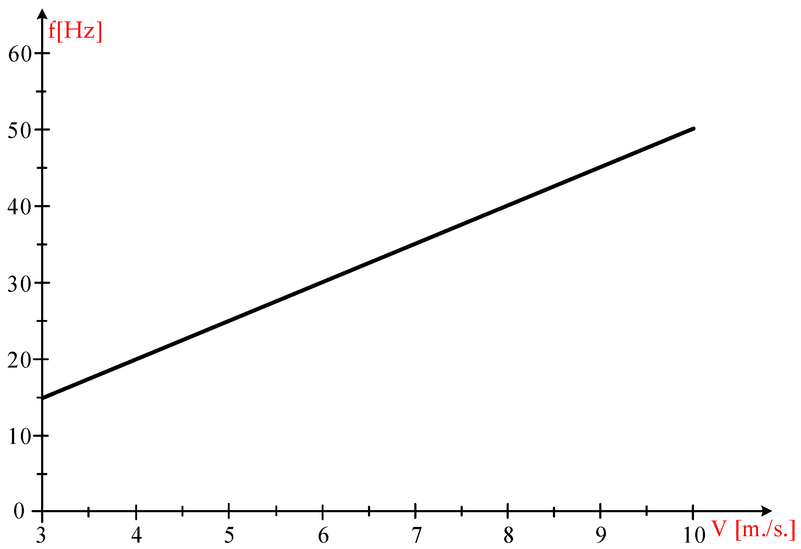
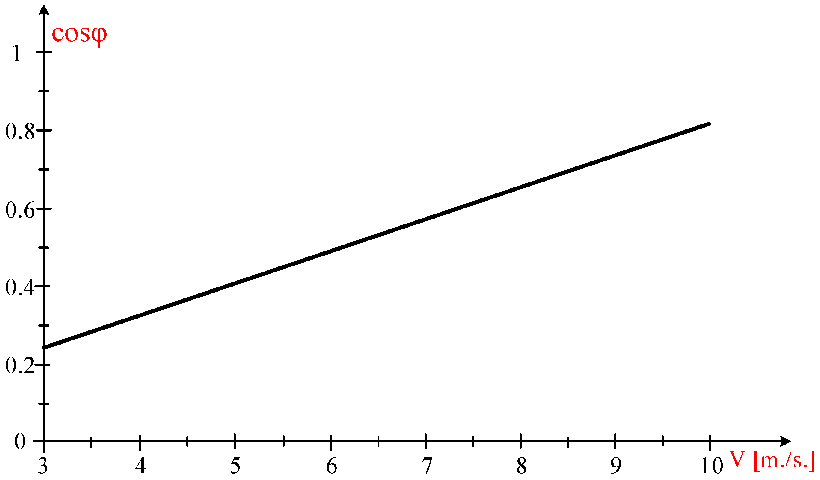
4.1. The Dependencies of Frequency, Steady-State Current, and Power Factor in Relation to Wind Speed

The static frequency, f, is adjusted to enable the operation of the wind turbine at maximum power points (MPPs) under optimal conditions, where ωOPTIM = 32.026·V, which is contingent upon the wind velocity, V. We consider the stationary regime, where the powers are equal, PWT(ω, V) = PEG(ω, f).
The wind speed varies from 3 m/s to 10 m/s, yielding the following results.
  • For V = 3 m/s:
    55 V 3 = 3 4.6 2 3.8179 10 2 1 0.15915 f ω 3.8179 10 2 + 3.8179 10 2 1 0.15915 f ω 2 f 2 + 1.31 50 2 ω = 32.026 V f = 15.233   Hz
  • For V = 4 m/s:
    55 V 3 = 3 4.6 2 3.8179 10 2 1 0.15915 f ω 3.8179 10 2 + 3.8179 10 2 1 0.15915 f ω 2 f 2 + 1.31 50 2 ω = 32.026 V f = 20.284   Hz
  • For V = 5 m/s:
    55 V 3 = 3 4.6 2 3.8179 10 2 1 0.15915 f ω 3.8179 10 2 + 3.8179 10 2 1 0.15915 f ω 2 f 2 + 1.31 50 2 ω = 32.026 V f = 25.231   Hz
  • For V = 6 m/s:
    55 V 3 = 3 4.6 2 3.8179 10 2 1 0.15915 f ω 3.8179 10 2 + 3.8179 10 2 1 0.15915 f ω 2 f 2 + 1.31 50 2 ω = 32.026 V f = 30.344   Hz
  • For V = 7 m/s:
    55 V 3 = 3 4.6 2 3.8179 10 2 1 0.15915 f ω 3.8179 10 2 + 3.8179 10 2 1 0.15915 f ω 2 f 2 + 1.31 50 2 ω = 32.026 V f = 35.347   Hz
  • For V = 8 m/s:
    55 V 3 = 3 4.6 2 3.8179 10 2 1 0.15915 f ω 3.8179 10 2 + 3.8179 10 2 1 0.15915 f ω 2 f 2 + 1.31 50 2 ω = 32.026 V f = 40.325   Hz
  • For V = 9 m/s:
    55 V 3 = 3 4.6 2 3.8179 10 2 1 0.15915 f ω 3.8179 10 2 + 3.8179 10 2 1 0.15915 f ω 2 f 2 + 1.31 50 2 ω = 32.026 V f = 45.260   Hz
  • For V = 10 m/s:
    55 V 3 = 3 4.6 2 3.8179 10 2 1 0.15915 f ω 3.8179 10 2 + 3.8179 10 2 1 0.15915 f ω 2 f 2 + 1.31 50 2 ω = 32.026 V f = 50.093   Hz
Table 1 systematizes the results obtained:
As can be seen from Figure 7, the stator frequency increases linearly with the wind speed value.
The value of the stator current, at constant stator flux, is
I s = U s R s + R s s 2 + X s c 2 = 4.6 3.8179 10 2 + 3.8179 10 2 1 0.15915 f ω 2 f 2 + 1.31 50 2
By substituting the mechanical angular speed, ω, with the optimal value ω = ωOPTIM = 32.026·V and incorporating the relationship between stator frequency and wind speed, f = 5·V, the resulting value is obtained:
I s = 4.6 3.8179 10 2 + 3.8179 10 2 1 0.15915 5 V ω 2 5 V 2 + 1.31 50 2 = 4.6 1 V 2 6.8644 10 4 V 2 + 0.14916
The variation of the static current with wind speed is illustrated in Figure 8.
At a wind speed of 10 m/s, the nominal current IN is determined to be 98 A. A linear variation of the current, expressed as I = 9.8·V, is validated by the relationship between the steady-state current and wind speed illustrated in Figure 9. Consequently, the electrical power delivered to the grid is
P E l = 3 U I cos φ = 3 4.6 5 V 9.8 V I cos φ = 676.2 V 2 cos φ
From the equality of the turbine powers, PWT(V) = 55·V3, with the generator PWT(V) = PEG(V), the generator power factor cos φ value is obtained:
cos φ = 55 V 3 676.2 V 2 = 8.1337 10 2 V
Figure 9 illustrates that the power factor ranges from 0.24401 to 0.81337, with the minimum value occurring at a wind speed of 3 m/s and the maximum value at a wind speed of 10 m/s.
The speed of the wind significantly affects both the quality of power delivered to the grid, as indicated by the power factor, and the quantity of power supplied, which is dependent on the cube of the wind speed. The higher the wind speed value, the higher the quality and value of power delivered to the grid.

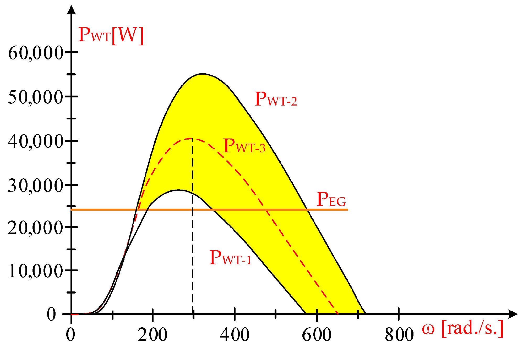
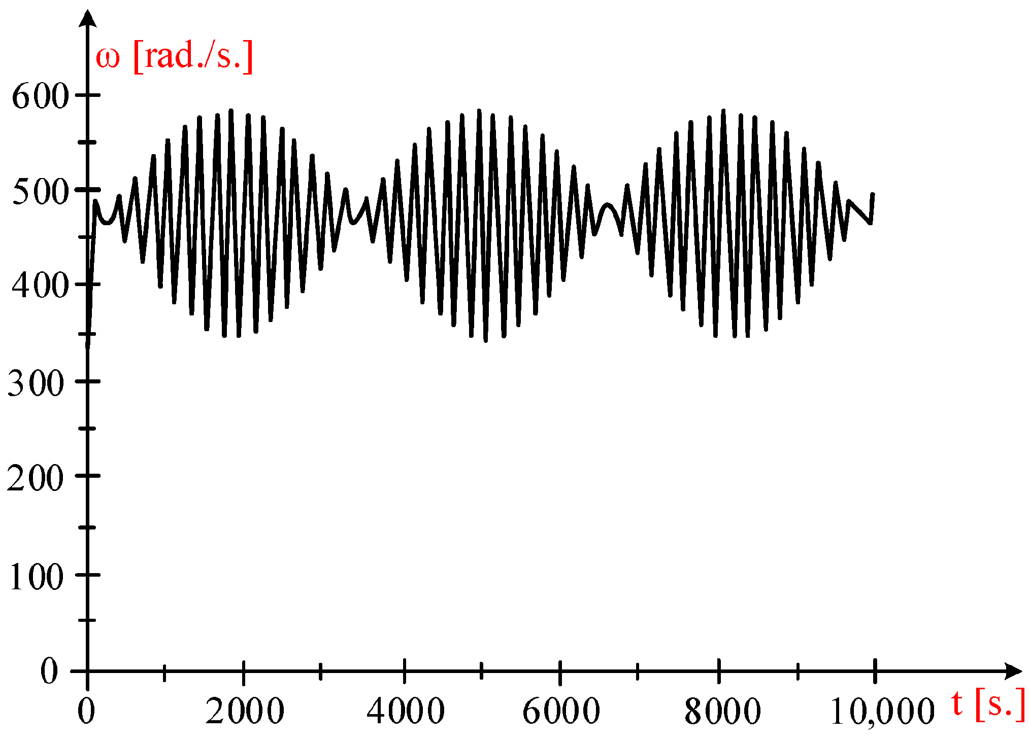
4.2. Wind System Behavior at Time-Varying Wind Speeds by Estimating the Wind Energy Captured by the Turbine

At constant wind speeds over time, the wind turbine is capable of operating at the maximum power point, MPP, by utilizing a suitable power prescription at the EG [8,26]. This can be accomplished through the Perturb and Observe Method, which is thoroughly examined in the literature [28] concerning the operation of wind installations in energetically optimal areas under stable wind speeds.
Given the variable wind speeds over time [11,12,43], the issue becomes complex due to the significant inertia moments. To operate within the optimal energy-efficient range, the mechanical angular speed must correspond with the temporal variations in wind speed.
As will be demonstrated subsequently, employing the mathematical model of WT, if the wind speed varies over time while the power output of the electric generator stays constant, the maximum wind energy that the turbines can capture will not be achieved. It is known that the optimal power value at the generator is contingent upon the mechanical angular speed, which is in turn is influenced by the wind speed.
Owing to the significant inertia moment [12,42], it is not feasible for the operation to consistently maintain the MPP, as the wind turbine’s rotational speed is unable to sufficiently adjust to the swift variations in wind speed over time [16,42], which requires an optimal rotational speed from an energy efficiency standpoint [11].
It is considered that the wind speed changes from V1 = 8 m/s to V2 = 10 m/s, having a sinusoidal variation of the form
V t = 9 + sin 9.43 10 2 t
At t = 0, the wind speed has the value V(0) = 9 m/s and the optimal MAS, ωOPTIM, corresponding to the speed of 9 m/s is
ω O P T I M = 32.026 V = 32.026 9 = 288.23   rad . / s
At ωOPTIM = 288.23 rad/s, the turbine operates at its maximum power point (Figure 10), with a constant generator power output.
P E G 0 = 33 9 3 = 24057   W   rad . / s
The turbine power characteristics are
  • For V1 = 8 m/s:
    P W T 1 ω , 8 = 19182 8 ω 1.3877 10 2 e 57.65 8 ω 8 3   W
  • For V2 = 10 m/s:
    P W T 2 ω , 10 = 19182 10 ω 1.3877 10 2 e 57.65 10 ω 10 3   W
  • For V3 = 9 m/s:
    P W T 3 ω , 9 = 19182 9 ω 1.3877 10 2 e 57.65 9 ω 9 3   W
From the power equation
J d ω d t ω = P W T P E G   W
with the total moment of inertia of the generator and turbine system, J = 0.7 kg m2, the obtained equation of motion is
0.7 d ω d t ω = P W T P E G   W
or
0.7 d ω d t ω = 19182 9 + sin 9.43 10 2 t ω 1.3877 10 2 e 57.65 9 + sin 9.43 10 2 t ω 9 + sin 9.43 10 2 t 3 33 9 3 d E W d t = 19182 9 + sin 9.43 10 2 t ω 1.3877 10 2 e 57.65 9 + sin 9.43 10 2 t ω 9 + sin 9.43 10 2 t 3 ω 0 = 288.23 E W 0 = 0
By solving the differential equations system, the MAS variation, ω, is obtained as illustrated in Figure 11, under the condition that the power at the generator remains constant at 24,057 W.
The wind energy harnessed by the turbine over a time span of 3500 s, EW(3500), is derived from the integration of the differential equation
d E W d t = P W T W
resulting in EW(3500) = 8.4251 × 10⁷ J.
The maximum wind energy that the turbine can capture in a time interval of 3500 s, EW-MAX(3500), is obtained by integrating the maximum power PWT-MAX:
E W M A X 3500 = 0 3500 P W T M A X d t = 0 3500 55 V 3 d t = 0 3500 55 9 + sin 9.43 10 2 t 3 d t = 1.4321 10 8 J
The electric energy supplied to the grid EE is derived from the integration of electrical power:
E E 3500 = 0 3500 P E G d t = 0 3500 33 9 3 d t = 0.841995 10 8 J
Upon comparing the energy values, it is evident that
(1)
The amount of electric energy supplied to the grid is 41.206% lower than the maximum wind energy that can be harnessed by the turbines:
E W M A X 3500 E E 3500 E W M A X 3500 100 = 1.4321 10 8 0.841995 10 8 1.4321 10 8 100 = 41.206 %
(2)
The wind energy harnessed by the turbine at PEG = 24,057 W is 41.17% than the maximum wind energy that the turbine is capable of capturing:
E W M A X 3500 E W 3500 E W M A X 3500 100 = 1.4321 10 8 8.425 10 7 1.4321 10 8 100 = 41.17 %

5. Discussion

This study examines the performance of medium-power wind turbines under significant variations in wind speed, with the turbines being equipped with short-circuited rotor induction generators and regulated through a power converter in the stator circuit. The load at the terminals of the electric generator was assumed to be constant.

5.1. Results

The most significant results are
  • Mathematical models for the generator and turbine have been established based on technical data from a 55 kW turbine;
  • The generator’s power was determined at a variable frequency while maintaining a constant stator flux;
  • The dependencies of the stator current and frequency on wind speed have been determined;
  • The wind-turbine-captured wind energy values were compared with the electrical energy supplied to the grid.

5.2. Fundamental Aspects

The results obtained highlight the following significant aspects:
  • When the load on the electric generator remains constant, the electrical energy supplied to the grid is more than twice as small as the maximum wind energy that can be harnessed by a wind turbine;
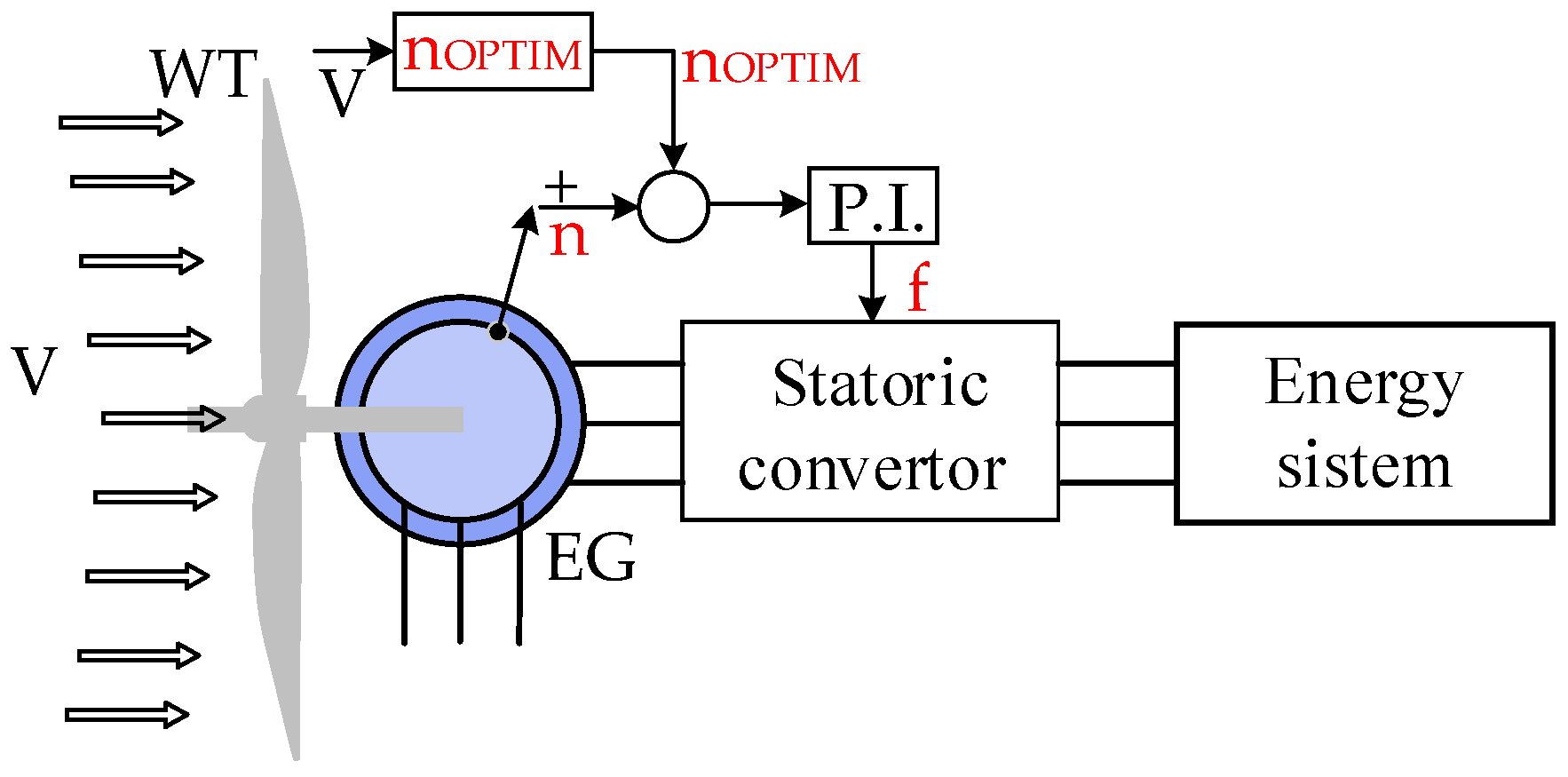
  • The operation of the turbine at its maximum power points necessitates the adjustment of the generator’s power output by regulating the stator frequency, thereby achieving optimal rotational speed.

5.3. Discussions

  • Utilizing a power converter within the stator circuit enables the turbine to operate at its maximum power point;
  • For optimal control, it is essential to accurately understand the dependence of the optimal mechanical angular speed on wind velocity.

6. Conclusions

This study examines the performance of high-power wind turbines equipped with short-circuited rotor induction generators and regulated through the use of a power converter in the stator circuit under significant variations in wind speed.
It has been demonstrated that adjusting the generator’s power according to the wind speed is essential.
Thus, the main contributions of the research can be highlighted as determining the dependences between generator power on wind speed and stator frequency and between generator frequency on wind speed, generator current, and generator power factor on wind speed. Comparative studies highlighted the captured wind energy at constant and variable wind speeds over time.
The primary outcomes achieved in this study are as follows:
-
Deduction of mathematical models for the 55 kW turbine and the induction generator from the technical data of the turbine (power characteristics, power dependence on rotational speed).
-
Analysis of the behavior of the induction generator under variable frequencies and controlled stator flux.
-
Determination of wind speed dependencies for the stator frequency and current as well as the power factor in the MPP operation mode of the turbine.
Also, simulation-based analysis at variable wind speeds with constant and variable power at the generator were conducted and the harvested wind energy at these power levels for the electric generator were provided.
The results obtained are genuinely beneficial for those who use wind energy systems and thus contribute to the existing specialized literature. Understanding and exploiting the relationship between wind speed and optimal MAS can unlock the full potential of variable-speed wind turbines and contribute to a sustainable energy future.

Author Contributions

Conceptualization, C.P.C. and E.S.; methodology, C.P.C. and G.-O.T.; software, C.P.C. and G.-O.T.; validation, C.P.C., G.-O.T. and E.S.; formal analysis, E.S.; investigation, C.P.C. and G.-O.T.; resources, E.S.; data curation, E.S.; writing—original draft preparation, C.P.C. and G.-O.T.; writing—review and editing, E.S.; visualization, G.-O.T. and E.S.; supervision, C.P.C.; project administration, C.P.C., G.-O.T. and E.S.; funding acquisition, C.P.C., G.-O.T. and E.S. All authors have read and agreed to the published version of the manuscript.

Funding

The publication of this article was supported by the 2024 Development Fund of the UBB.

Institutional Review Board Statement

Not applicable.

Informed Consent Statement

Not applicable.

Data Availability Statement

The data presented in this study are available upon request from the first author.

Conflicts of Interest

The authors declare no conflicts of interest. The funders had no role in the design of the study; in the collection, analyses, or interpretation of data; in the writing of the manuscript; or in the decision to publish the results.

Abbreviations

The following abbreviations are used in this manuscript:
WTwind turbine
MPPmaximum power point
MASmechanical angular speed
EGelectric generator
PIDproportional, integrative, derivative
Vwind speed
Jequivalent moment of inertia
PWTpower given by WT relative to the shaft of the electric generator
PWT-MAXmaximum power value from the wind turbine
PEGpower of the electric generator
PNrated power
EEelectric energy supplied to the grid
EWwind energy
EW-MAXmaxim wind energy
MWTmoment provided by WT, relative to the EG shaft
MEGelectromagnetic moment at the EG shaft
UNrated voltage
USstator voltage
INnominal current
ISstator current
IRrotor current
RSstator resistance
RRrotor resistance
Xscshort-circuit reactance
XRrotor reactance
XMmagnetizing reactance
N1number of turns per phase in the stator
N2number of turns per phase in the rotor
fNnominal frequency
ωmechanical angular velocity
ωNnominal mechanical angular velocity
ωOPTIMoptimal mechanical angular velocity
ωMAXIMmaxim mechanical angular velocity
ktransformation ratio
kTtransmission multiplication ratio
kpproportionality factor
p1number of poles
nNnominal speed
n1rotational speed of the spinning field
nrotor’s rotational speed
sNnominal sliding
cos φgenerator power factor
a, b, cparameters of the wind turbine

References

  1. Ciucci, M. Energia Din Surse Regenerabile. Available online: https://www.europarl.europa.eu/factsheets/ro/sheet/70/energia-din-surse-regenerabile (accessed on 22 May 2025).
  2. Electricity and Heat Statistics. Available online: https://ec.europa.eu/eurostat/statistics-explained/index.php?title=Electricity_and_heat_statistics (accessed on 21 June 2025).
  3. Evolution of Wind Energy in Europe. Available online: https://www.iberdrola.com/sustainability/wind-power-evolution-europe (accessed on 21 June 2025).
  4. Bishoge, O.K.; Zhang, L.L.; Mushi, W.G. The Potential Renewable Energy for Sustainable Development in Tanzania: A Review. Clean Technol. 2019, 1, 70–88. [Google Scholar] [CrossRef]
  5. Sachin, G.; Shree, K.M.; Shivam, K.; Deepesh, A. A Consolidation Review of Major Wind Turbine Models in Global Market. In Proceedings of the 2020 International Conference on Power Electronics & IoT Applications in Renewable Energy and Its Control (PARC), Mathura, India, 28–29 February 2020. [Google Scholar]
  6. Khajah, A.M.H.A.; Philbin, S.P. Techno-Economic Analysis and Modelling of the Feasibility of Wind Energy in Kuwait. Clean Technol. 2022, 4, 14–34. [Google Scholar] [CrossRef]
  7. Sajadi, A.; Clark, K.; Loparo, K.A. Statistical Steady-State Stability Analysis for Transmission System Planning for Offshore Wind Power Plant Integration. Clean Technol. 2020, 2, 311–332. [Google Scholar] [CrossRef]
  8. Sorandaru, C.; Ancuti, M.-C.; Musuroi, S.; Svoboda, M.; Muller, V.; Geza Erdodi, M. Fundamental Issue for Wind Power Systems Operating at Variable Wind Speeds: The Dependence of the Optimal Angular Speed on the Wind Speed. In Proceedings of the 2022 International Conference and Exposition on Electrical And Power Engineering (EPE), Iasi, Romania, 20–22 October 2022. [Google Scholar]
  9. Routray, A.; Hur, S.H. Power regulation of a wind farm through flexible operation of tur-bines using predictive control. Energies 2024, 313, 133917. [Google Scholar]
  10. Carstea, C.; Butaru, F.; Ancuti, M.-C.; Musuroi, S.; Deacu, A.; Babaita, M. Wind Power Plants Operation at Variable Wind Speeds. In Proceedings of the 2020 IEEE 14th International Symposium on Applied Computational Intelligence and Informatics (SACI), Timisoara, Romania, 21–23 May 2020. [Google Scholar]
  11. Sorandaru, C.; Musuroi, S.; Frigura-Iliasa, F.M.; Vatau, D.; Dordescu, M. Analysis of the Wind System Operation in the Optimal Energetic Area at Variable Wind Speed over Time. Sustainability 2019, 11, 1249. [Google Scholar] [CrossRef]
  12. Huynh, P.; Tungare, S.; Banerjee, A. Maximum Power Point Tracking for Wind Turbine Using Integrated Generator–Rectifier Systems. IEEE Trans. Power Electron. 2020, 56, 730–739. [Google Scholar]
  13. Hussain, J.; Mishra, M.K. An Efficient Wind Speed Computation Method Using Sliding Mode Observers in Wind Energy Conversion System Control Applications. IEEE Trans. Ind. Appl. 2020, 56, 730–739. [Google Scholar] [CrossRef]
  14. Edrah, M.; Zhao, X.; Hung, W.; Qi, P.; Marshall, B.; Karcanias, A. Effects of POD Control on a DFIG Wind Turbine Structural System. IEEE Trans. Energy Convers. 2020, 35, 765–774. [Google Scholar] [CrossRef]
  15. Deng, X.; Yang, J.; Sun, Y.; Song, D.; Yang, Y.; Joo, Y.H. An Effective Wind Speed Estimation Based Extended Optimal Torque Control for Maximum Wind Energy Capture. IEEE Access 2020, 8, 65959–65969. [Google Scholar] [CrossRef]
  16. Karthik, R.; Sri Hari, A.; Pavan Kumar, Y.V.; John Pradeep, D. Modelling and Control Design for Variable Speed Wind Turbine Energy System. In Proceedings of the 2020 International Conference on Artificial Intelligence and Signal Processing (AISP), Amaravati, India, 10–12 January 2020. [Google Scholar]
  17. Xingjia, Y.; Yingming, L.; Jieqiu, B.; Zuoxia, X. Research and simulation of direct drive wind turbine VSCF characteristic. In Proceedings of the IEEE International Conference on Automation and Logistics, Qingdao, China, 1–3 September 2008. [Google Scholar]
  18. Ravanji, M.H.; Parniani, M. Stability Assessment of DFIG-Based Wind Turbines Equipped with Modified Virtual Inertial Controller under Variable Wind Speed Conditions. In Proceedings of the 43rd Annual Conference of the IEEE-Industrial-Electronics-Society (IECON), Beijing, China, 29 October–1 November 2017. [Google Scholar]
  19. Soued, S.; Ramadan, H.S.; Becherif, M. Effect of Doubly Fed Induction Generator on Transient Stability Analysis under Fault Conditions. In Proceedings of the 6th International Conference on Emerging and Renewable Energy—Generation and Automation (ICEREGA), Sousse, Tunisia, 28–30 October 2018. [Google Scholar]
  20. Hua, Y.; Yujun, D.; Liye, X.; Qionglin, L.; Chen, Z.; Yi, W. Hydro-Tower Pumped Storage-based Wind Power Generator: Short-term Dynamics and Controls. In Proceedings of the 2nd Asian Conference on Frontiers of Power and Energy (ACFPE), Chengdu, China, 20–22 October 2023. [Google Scholar]
  21. Jannet, J.; Fouizi, M. Model of wind turbine-pumped storage hydro plant. In Proceedings of the 9th International Renewable Energy Congress (IREC), Hammamet, Tunisia, 20–22 March 2018. [Google Scholar]
  22. Papakonstantinou, A.G.; Konstanteas, A.I.; Papathanassiou, S.A. Solutions to Enhance Frequency Regulation in an Island System With Pumped-Hydro Storage Under 100% Renewable Energy Penetration. IEEE Access 2023, 11, 76675–76690. [Google Scholar] [CrossRef]
  23. Yingyu, A.; Li, Y.; Zhang, J.; Wang, T.; Liu, C. Enhanced Frequency Regulation Strategy for Wind Turbines Based on Over-speed De-loading Control. In Proceedings of the 5th Asia Conference on Power and Electrical Engineering (ACPEE), Chengdu, China, 4–7 June 2020. [Google Scholar]
  24. Fan, F.; Crisostomi, E.; Zhang, B.; Thomopulos, D. Rotor Speed Fluctuation Analysis for Rapid De-Loading of Variable Speed Wind Turbines. In Proceedings of the IEEE 20th Mediterranean Electrotechnical Conference (MELECON), Palermo, Italy, 16–18 June 2020. [Google Scholar]
  25. Ravanji, M.H.; Parniani, M. Small-Signal Stability Analysis of DFIG-based Wind Turbines Equipped with Auxiliary Control Systems under Variable Wind Speed. In Proceedings of the 20th IEEE International Conference on Environment and Electrical Engineering (EEEIC)/4th IEEE Industrial and Commercial Power Systems Europe Conference (I and CPS Europe), Electr Network, Madrid, Spain, 9–12 June 2020. [Google Scholar]
  26. Rebello, E.; Watson, D.; Rodgers, M. Performance Analysis of a 10 MW Wind Farm in Providing Secondary Frequency Regulation: Experimental Aspects. IEEE Trans. Power Syst. 2019, 34, 3090–3097. [Google Scholar] [CrossRef]
  27. EC Wind 55kW Wind Turbine. Available online: https://eco-energ.co.uk/wind/ec-wind-55kw-wind-turbine/ (accessed on 21 June 2025).
  28. Dobrin, E.; Ancuti, M.-C.; Musuroi, S.; Sorandaru, C.; Ancuti, R.; Lazar, M.A. Dynamics of the Wind Power Plants at Small Wind Speeds. In Proceedings of the 2020 IEEE 14th International Symposium on Applied Computational Intelligence and Informatics (SACI), Timisoara, Romania, 21–23 May 2020. [Google Scholar]
  29. Pesut, N.D.; Ciric, R.M. An efficient method for speed control of induction wind turbine generator with dual AC-DC-AC converter. Wind Eng. 2022, 46, 993–1008. [Google Scholar] [CrossRef]
  30. Ge, M.W.; Ke, W.M.; Chen, H.X. Pitch control strategy before the rated power for variable speed wind turbines at high altitudes. J. Hydrodynam. 2019, 31, 379–388. [Google Scholar] [CrossRef]
  31. Micon M 300-55. Available online: https://en.wind-turbine-models.com/turbines/1305-micon-m-300-55 (accessed on 1 April 2025).
  32. Baala, Y.; Bri, S. DFIG-Based Wind Turbine Control Using High-Gain Observer. In Proceedings of the 1st International Conference on Innovative Research in Applied Science, Engineering and Technology (IRASET), Meknes, Morocco, 16–19 April 2020. [Google Scholar]
  33. Vadi, S.; Gürbüz, F.B.; Bayindir, R.; Hossain, E. Design and Simulation of a Grid Connected Wind Turbine with Permanent Magnet Synchronous Generator. In Proceedings of the 8th IEEE International Conference on Smart Grid, Paris, France, 17–19 June 2020. [Google Scholar]
  34. Gao, G.; Chen, W. Design Challenges of Wind Turbine Generators. In Proceedings of the 29th Electrical Insulation Conference, Montreal, QC, Canada, 31 May–3 June 2009. [Google Scholar]
  35. Han, Y.; Kim, S.; Ha, J.-I.; Lee, W.-J. A Doubly Fed Induction Generator Controlled in Single-Sided Grid Connection for Wind Turbines. IEEE Trans. Energy Convers. 2013, 28, 413–424. [Google Scholar] [CrossRef]
  36. Chioncel, C.P.; Spunei, E.; Tirian, G.-O. Visualizing the Maximum Energy Zone of Wind Turbines Operating at Time-Varying Wind Speeds. Sustainability 2024, 16, 2659. [Google Scholar] [CrossRef]
  37. Chioncel, C.P.; Spunei, E.; Tirian, G.-O. Wind Turbines Around Cut-In Speed: Startup Optimization and Behavior Analysis Reported to MPP. Appl. Sci. 2025, 15, 3026. [Google Scholar] [CrossRef]
  38. Chioncel, C.P.; Tirian, O.G.; Dordescu, M.; Spunei, E. Optimization of wind turbine operation in variable wind speed conditions. In Proceedings of the 7th International Conference on Energy Efficiency and Agricultural Engineering (EE and AE), Ruse, Bulgaria, 12–14 November 2020. [Google Scholar]
  39. Wu, Z.Q.; Hou, L.C.; Cao, B.L.; Ma, B.Y.; Hu, X.Y. Cooperative Control for Wind Turbines Based on Hamilton System Under Limited Input. Int. J. Control Autom. Syst. 2023, 21, 2605–2614. [Google Scholar] [CrossRef]
  40. Chioncel, C.P.; Ciucurita, S.; Spunei, E. Control of Wind-Power Systems Operating at Variable Wind Speeds to Optimize Energy Capture. Energies 2024, 18, 2574. [Google Scholar] [CrossRef]
  41. Siemens, Motor 55 KW at DOL Operation. Available online: https://ausschreibungstexte.siemens.com/tiplv/Data/E/Drive_Technology,_Automat/Dr/Low_/I/1LE1_-_SIMOTICS_GP_and_SIMOTICS_SD_standard_motors_%280,/I/2/Motor__DPMD_AAF229_001_000__kW_at_DOL_operation,__DPMD_AAD769_001_000__housing,_FS___DPMD_AAA726_001_000_,__DPMD_ACB254_001_000_,__DPMD_AA/(LV_HVT8GHVAWMTMVFSCP1DTHS657W_1LE1504-2CA23-4AA4) (accessed on 28 June 2025).
  42. Babescu, M. Masina Sincrona—Modelare—Identificare—Simulare; Publisher Polityehnica Timisoara: Timisoara, Romania, 2003; ISBN 973-625-021-0. [Google Scholar]
  43. Chioncel, C.P.; Spunei, E.; Tirian, G.-O. The problem of power variations in wind turbines operating under variable wind speeds over time and the need for wind energy storage systems. Energies 2024, 17, 5079. [Google Scholar] [CrossRef]
Figure 1. The variation in electricity production based on the energy source.
Applsci 15 07700 g001
Figure 2. The variation in installed capacity of wind power plants across Europe.
Applsci 15 07700 g002
Figure 3. The power characteristics.
Applsci 15 07700 g003
Figure 4. Generator power characteristics.
Applsci 15 07700 g004
Figure 5. Power dependence on frequency and angular velocity at a constant stator flux.
Applsci 15 07700 g005
Figure 6. Wind system with induction generator and stator converter.
Applsci 15 07700 g006
Figure 7. Dependence of the frequency on wind speed.
Applsci 15 07700 g007
Figure 8. Dependence of the stator current on wind speed.
Applsci 15 07700 g008
Figure 9. The dependence of the power factor on wind speed.
Applsci 15 07700 g009
Figure 10. Turbine power characteristics.
Applsci 15 07700 g010
Figure 11. MAS variation.
Applsci 15 07700 g011
Table 1. Frequency dependence on wind speed.
V [m/s]f [Hz]
315.233
420.493
525.321
630.344
735.347
840.325
945.26
1050.877
Disclaimer/Publisher’s Note: The statements, opinions and data contained in all publications are solely those of the individual author(s) and contributor(s) and not of MDPI and/or the editor(s). MDPI and/or the editor(s) disclaim responsibility for any injury to people or property resulting from any ideas, methods, instructions or products referred to in the content.

