Article

A Double Closed-Loop Process for Nanoparticle Synthesis via Aerosol Mixing and Venturi Jet Scrubbing

1
DICCA, Department of Civil, Chemical and Environmental Engineering, Polytechnic School, University of Genova, Via Opera Pia 15, 16145 Genova, Italy
2
DIFI, Department of Physics, University of Genova, Via Dodecaneso 33, 16146 Genova, Italy
3
DCCI, Department of Chemistry and Industrial Chemistry, University of Genova, Via Dodecaneso 31, 16146 Genova, Italy
*
Author to whom correspondence should be addressed.
Appl. Sci. 2025, 15(14), 7693; https://doi.org/10.3390/app15147693
Submission received: 4 June 2025 / Revised: 7 July 2025 / Accepted: 7 July 2025 / Published: 9 July 2025

Abstract

Inorganic nanoparticles (NPs) have been synthesised via mixing and coalescence of droplets containing precursors and entrained by gaseous streams. The droplets have been generated by ultrasonic aerosolisation of two different liquid phases, each containing the respective reagent. The as-produced NPs are trapped by mixing with a liquid phase in a Venturi nozzle, acting simultaneously as a collector and concentrator of the solid nanosized phase produced. Commercial electrically powered ultrasonic aerosolising devices have been adapted to atomise salt solutions characterised by high electrical conductivity. This process allowed the synthesis of calcium carbonate NPs with an average diameter in the range of (34–52) nm, according to the concentration of precursors in the aerosolised phases. This closed-loop method of synthesis, where neither capping agents were used nor demanding operating conditions were adopted, can represent a safe and viable eco-friendly technique for NP production free of undesirable compounds, as required for pharmaceutical preparations and theranostic uses.

1. Introduction

Nowadays, nanotechnology has assumed a key role in modern manufacturing, with promising uses in the most diverse sectors. Notably, the ongoing energy transition brings many changes in design concepts, materials, equipment and process operation, possibly giving rise to safety implications: the main trends and challenges are identified in the use of nanomaterials in battery storage, hydrogen production [1] and novel energy storage solutions [2]. Thanks to nanotechnology development, a high degree of interdisciplinarity is realised between chemistry and materials physics [3], with applications in intermetallic alloys and compounds [4], in semiconductor technology and nanofluid manufacturing for heat transfer [5]. On that note, Kulandaivel et al. [6] authored a thorough survey focused on many different types of NP dispersion in suitable fluids and discussed the basic technical problems related to how physicochemical properties of solvents and suspended solids may influence the performance of the relevant nanofluids. As a first rough classification, NPs can be grouped into organic and inorganic ones [7]. Both types can be advantageously used to coat surfaces to fight bacterial proliferation, a technique of primary importance in biomedical technology, preventing secondary infections caused by biofilms adhering to surfaces of surgical instruments and medical devices [8]. In a different, though related context, metal NP–polymer composites based on Ag NPs proved to be highly efficient in antibacterial packaging [9].
Compared to organics, inorganic NPs have perhaps received more attention over the years, as evidenced by the development of different synthesis techniques depending on the process variables to be optimised [10]. Likewise, their noxious effect on living organisms has been identified and discussed, owing to their high permeability through cell membranes [11]. A common aspect of the various synthesis methods is the need to have as tight a diameter distribution curve as possible, and this need is also often considered essential from a commercial point of view. Shape control is another basic target, as many specific properties of NPs depend on their structural configuration at the nanoscale [12]. To this purpose, hydrodynamics and other operating conditions may have a key role in determining the physical properties of the final nanosized product [13]. As is well known, the NPs’ structural configuration is a paramount variable in optoelectronics, with particular reference to the manufacture of optical filters and photonic crystals [14].
Physical and chemical processes are the two cornerstones on which the vast majority of laboratory- and industrial-scale synthesis methods are based [15], while biological methods, in which micro-organisms, algae or fungi act as nanofactories or living nano-reactors, are still undergoing extensive research but have not found substantial acceptance for large-scale production [16]. Physical synthesis methods, including sputtering, pulsed laser ablation, vapour deposition, wire explosion and lithographic methods, may produce nearly monodispersed NPs at a price of a costly manufacturing setup, but there are exceptions [17]. In fact, top-down comminution methods, at a dry state or in the presence of a solvent dispersing the as-produced NPs, represent a class of economically promising physical methods that have been experimentally tested in the preparation of noble metals dispersions stabilised by specific capping agents [18].
Chemical methods probably represent the largest chapter in nanosynthesis and are applied in the most diverse ways, depending on whether NPs consist of free-state elements or compounds. Very often, the synthesis processes are carried out at drastic operating conditions, and this situation typically pertains to dry synthesis methods, like pyrolysis processes [19], or wet chemical methods, like thermal dissociations, typical of polyol processes. Interestingly, after a period of opposition, both from the scientific community and from the media, due to the use of reagents that were toxic to humans or harmful to the environment, chemical methods have experienced a revamping/renaissance [20], thanks to the use of environmentally friendly reagents of natural origin [21], like plant extracts often used as reductants, under the paradigms of environmental sustainability [22]. In this context, the operating conditions for synthesis are milder, even in terms of energy demand, and this is the second aspect that the recent trend lines are inspired by.
Aerosol processes have been mainly adopted in NP synthesis where high temperatures are required, as in the case of thermostable NPs produced by spray flame aerosol reactors [23]. Venturi reactors [24] represent a more unusual choice in nanosynthesis, although they have been extensively used in gas adsorption and stripping, due to their advantages in terms of interphase mass transfer. They can be considered as a variant of jet reactors, which have already been proposed in inorganic NP synthesis [25]. A common drawback affecting these methods, relying upon hydrodynamic regimes of precursor mixing, stems from a high particle diameter polydispersity requiring minimisation. To this end, in the present study, a Venturi nozzle is used for the sole purpose of acting as a particle collector, capturing CaCO3 NP synthesised by mixing two different aerosolised phases, each of them containing one reactant. The novelty of this approach lies in the use of a closed circuit both for gaseous and liquid streams, in order to create both a water- and gas-tight process. As a consequence, such an inherently safer design allows minimising NP dispersion in the environment while also respecting the paradigms of green nanosynthesis. Another key aspect is that this process is carried out at room temperature, achieving the dual benefits of reducing risks to operators and avoiding the energy waste associated with heating precursors.
The paper is divided as follows: In Section 2, the utilised reagents and the plant setup are described. In Section 3, the results are discussed and compared with those obtained by different synthesis techniques, including aerosol chemical reactors. In Section 4, the conclusions are drawn and directions for future research are put forward.

2. Materials, Methods and Experimental Setup

2.1. Chemicals and Reaction Scheme

Calcium chloride (CaCl2, 99.9%, Sigma-Aldrich, Milano, Italy) and sodium carbonate (Na2CO3, 99.5%, Labbox, Milano, Italy) were used as purchased. Deionised water was used in all experimental samples, which were carried out at room temperature (20 °C).
The chemical reaction for the synthesis of CaCO3 NPs is as follows:
CaCl2 + Na2CO3 → CaCO3 + 2NaCl
Essentially, the aforementioned reaction can be described by the following scheme:
A + B → C + D
where A (CaCl2) is a reagent dissolved in droplets produced by a first aerosoliser, while B (Na2CO3) is the second reagent present in droplets produced by a second aerosoliser. The solid phase C, made of CaCO3 NPs, is formed by the coalescence of droplets contained in the nebulised phases produced by the two aforementioned independent aerosolisation processes. The as-produced nanosized phase C is then captured by mixing in a liquid medium in a Venturi nozzle according to the schemes, which will be described in Section 2.3.

2.2. Characterisation Techniques

The NPs were characterised in diameter by dynamic light scattering (DLS, Zetasizer Nano, Malvern Instruments, Malvern, UK), using a polystyrene cuvette where an aliquot of water embedding the as-formed NPs is dropped. The final diameter distribution curve is the average of 20 different distribution plots obtained by the instrument at sequential times. The NPs were characterised in shape and composition by field emission scanning electron microscopy (FESEM, Supra40VP, Carl Zeiss, Oberkochen, Germany) operating at a maximum voltage of 30 kV and at a maximum magnification of 500,000×. The liquid medium, in which NPs are dispersed at the end of the synthesis process, is sonicated and further drop-spread on a mica surface. Finally, the deposited NPs are dried under vacuum and covered by a layer of graphitic carbon by physical vapour deposition (PVD).

2.3. The Experimental Setup

In Figure 1, a scheme of the comprehensive experimental setup relying upon ultrasonic aerosolisation is reported. The overall setup components are as follows:
-
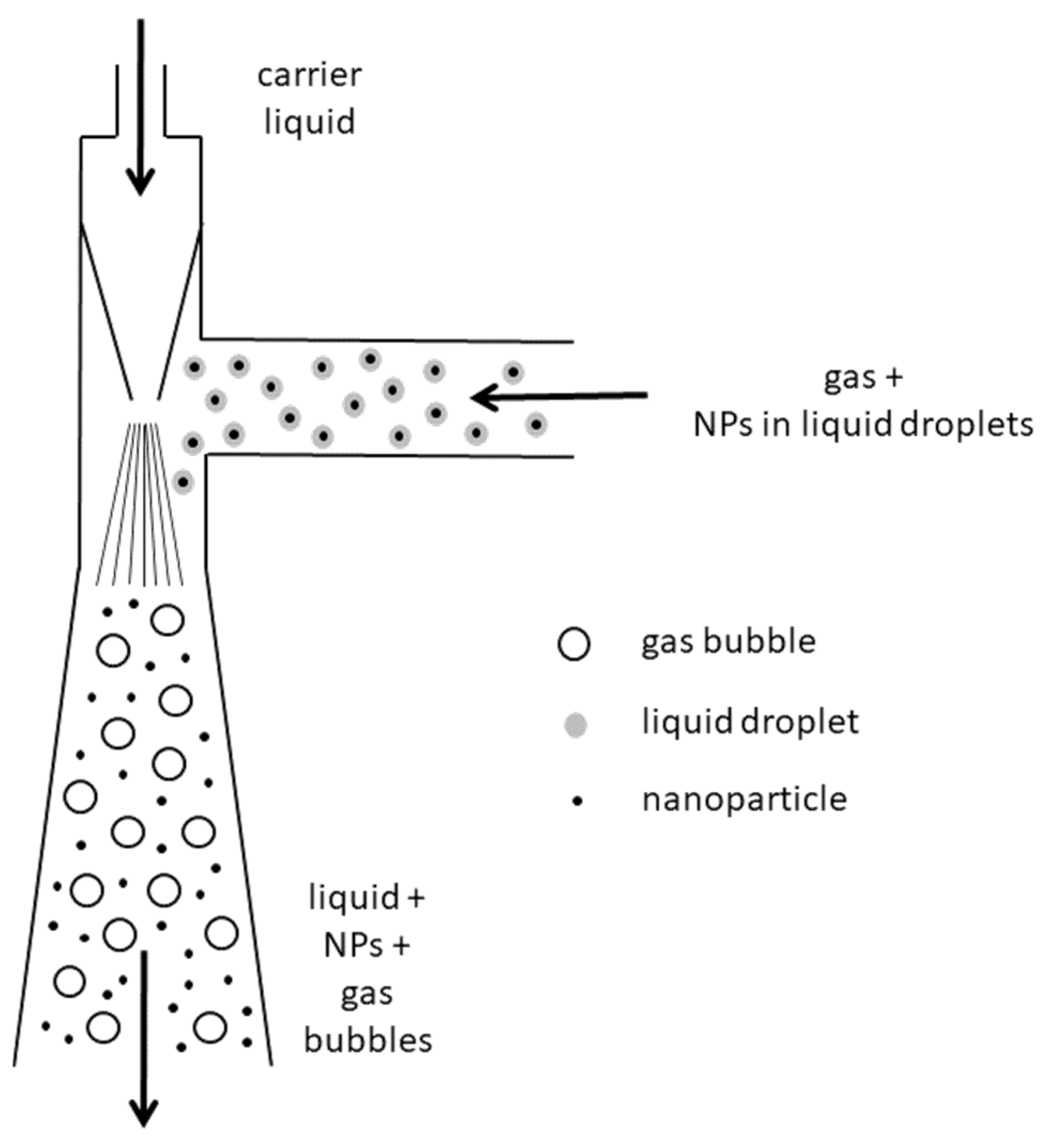
A glass vessel, whose upper flange is crossed by a water supply line, a water outlet line and a Venturi nozzle outlet line. From this point on, this vessel will be named the “Venturi vessel” to avoid confusion with the aerosoliser container, called the “atomising vessel”
-
A Venturi nozzle, whose outlet pipe draws directly into the vessel.
-
A five-chamber diaphragm pump (Seaflo, 24 V, 240 W) for circulating the water phase, operating at a maximum outlet pressure of 4 bar. This pump draws water from the vessel and sends it to the Venturi reactor inlet.
-
An analogic manometer measuring water pressure at the Venturi reactor inlet;
-
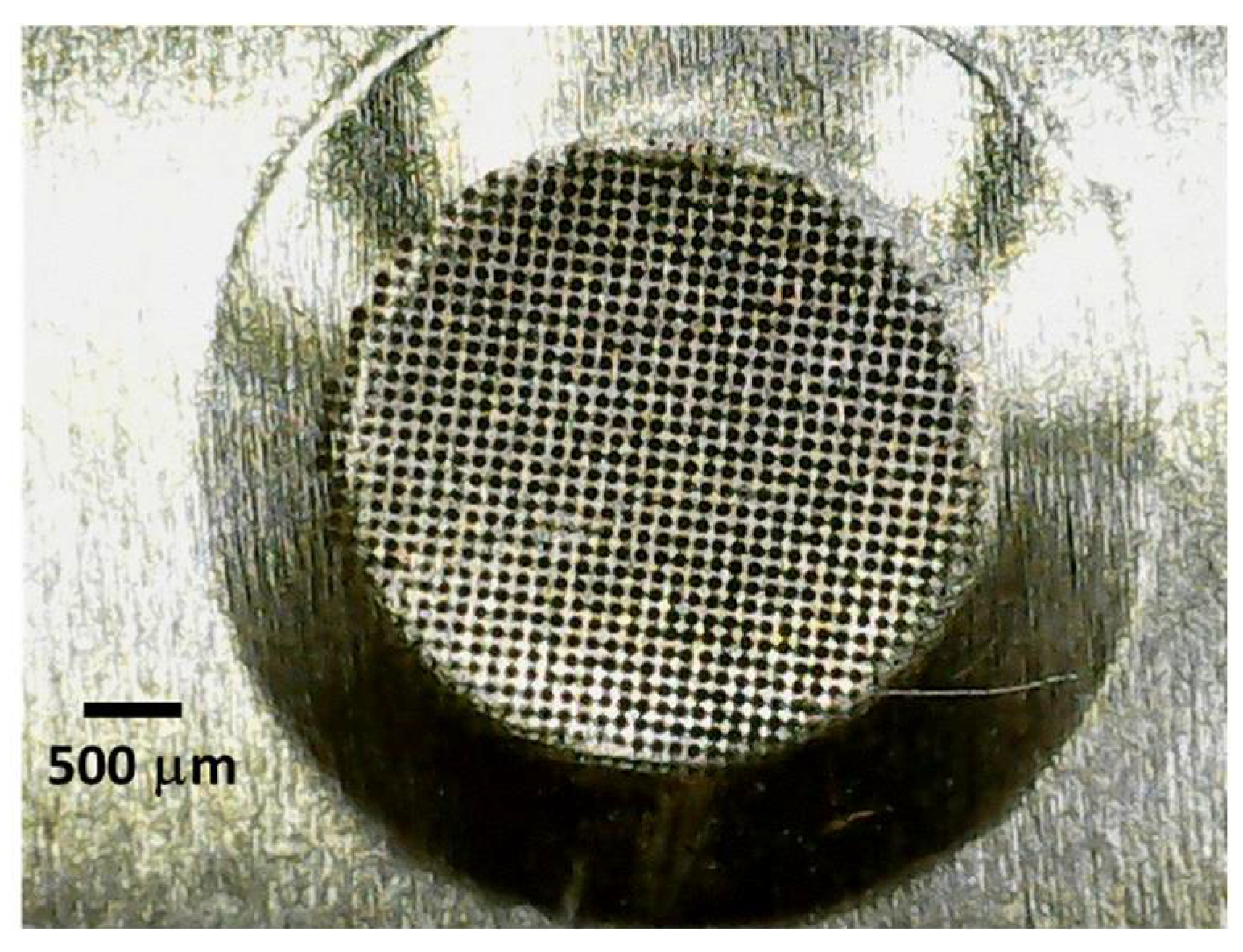
Two ultrasonic aerosolisers, each one comprising a reservoir (the atomising vessel) containing chemical reagents A and B indicated in Equation (2), namely one reagent for each aerosoliser, equipped with an inlet and outlet duct. The former receives the outgoing air from the Venturi vessel; the latter conveys the gaseous stream containing the liquid droplets into a T-junction where the outgoing streams from each aerosoliser merge together. This T-shaped device acts as a chemical reactor, promoting the coalescence between droplets containing two different reagents, thus forming bigger droplets containing NPs of the product C.
-
A boosting gas compressor (Tungfull Digital Technology, Shenzhen, China, 24 V, 10 W), operating with adjustable flow rate, is located on the gas line between the outlet of the Venturi vessel and the inlet of the two aerosolisers. Its purpose is to improve the circulation of the gas stream by counteracting pressure drops in the gas line. The compressor motor is equipped with a dedicated, custom-made water-cooling coil.
-
Two adjustable DC power suppliers (Longwei, LW-K3010D; 0–30 V; 300 W) were adopted. One of the two is used to run the water circulation pump in the Venturi nozzle, while the other powers the boosting compressor mentioned in the previous point.
-
One fixed DC power supplier (5 V; 20 W) to power the electrical circuit of each atomiser and the relevant cooling fan.
In essence, the experimental setup described in Figure 1 is based on two closed-circuit streams, namely,
-
A closed-loop water circulation to ensure the operation of the Venturi nozzle, whose sole purpose is to capture the liquid droplets coming from the T-joint and containing NPs of product C;
-
A closed-loop gas stream, exiting the vessel and forming two gas currents of equal flow rate entering the aerosolisers.
For a better visualisation, the closed-loop liquid, gas and aerosolised streams are reported in solid, dotted and dashed lines, respectively.
In Figure 2, a scheme of the Venturi nozzle is reported. It consists of a supply duct terminating in a converging nozzle. As the carrier fluid passes through the nozzle, it forms a vacuum by which air and droplets coming from the T-joint are sucked in and further mixed with the carrier liquid. The high turbulence produced downstream of the nozzle causes the abatement of NPs, which are thus trapped by the liquid, finally collected in an underlying vessel.
Two different experimental configurations have been tested. Both of them rely on the same Venturi nozzle collector, but they differ from one another in the way in which the aerosolised phases are generated. In fact, the experimental setup initially used was based on an indirect ultrasonic aerosolisation process, while the one subsequently used relied on a direct aerosolisation process.
In Figure 3, the differences between the two mentioned nebulisation techniques are highlighted. In an indirect aerosoliser, a submerged piezoelectric plate, oscillating at a constant resonance frequency, produces vibrations in a volume of water acting as an auxiliary fluid, which, in turn, transmits these vibrations to the meniscus of a separated liquid phase where a reagent is dissolved, giving a stream of aerosolised droplets. The auxiliary liquid has the sole function of energy transfer between the piezoelectric transducer and the liquid subject to aerosolisation, which is located in a thin-wall polymeric vessel surrounded by the auxiliary liquid. On the other hand, a direct aerosolisation technique relies on direct contact between an oscillating metal plate and a liquid containing a reagent, without resorting to an auxiliary fluid acting as an energy vector. In particular, the liquid containing a reagent is placed in a container, where a wick is located in the middle, which imbibes by capillarity, bringing the liquid into contact with the vibrating metal plate. The latter, 16 mm in diameter, has a finely perforated central area, 3.5 mm in diameter, which is permeable to the solution. The latter is thus finely atomised, producing a stream of droplets containing a reagent. An enlarged image of the micro-holes on the vibrating lamella is shown in Figure 4.
In Figure 5a, a photograph of the ultrasonic atomiser driver circuit, connected with the atomiser plate, is reported. The operating tension is 5 V, with a power input of 2 W and a resonant frequency in the range 103–113 kHz. The frequency transducer, namely the atomising device, acts as a capacitor and consists of two metallic plates separated by a dielectric layer. The upper plate is shaped in the form of a circular crown, while the lower one has a central pitted area, as previously said.
In its original commercial version, as reported in Figure 5b, the vibrating plate is suitable for atomising solutions with low or negligible electrical conductivity, typical of weakly polar organic substances dispersed in an aqueous solvent. This makes the device unsuitable for atomising saline solutions, whose electrical conductivity compromises the operation of the capacitive atomiser, resulting in overheating and rapid deterioration of the power circuit, which happened during the first experiments using a commercial product as is. For this reason, the atomiser plate has been customarily modified as depicted in Figure 5c by adopting the following amendments:
-
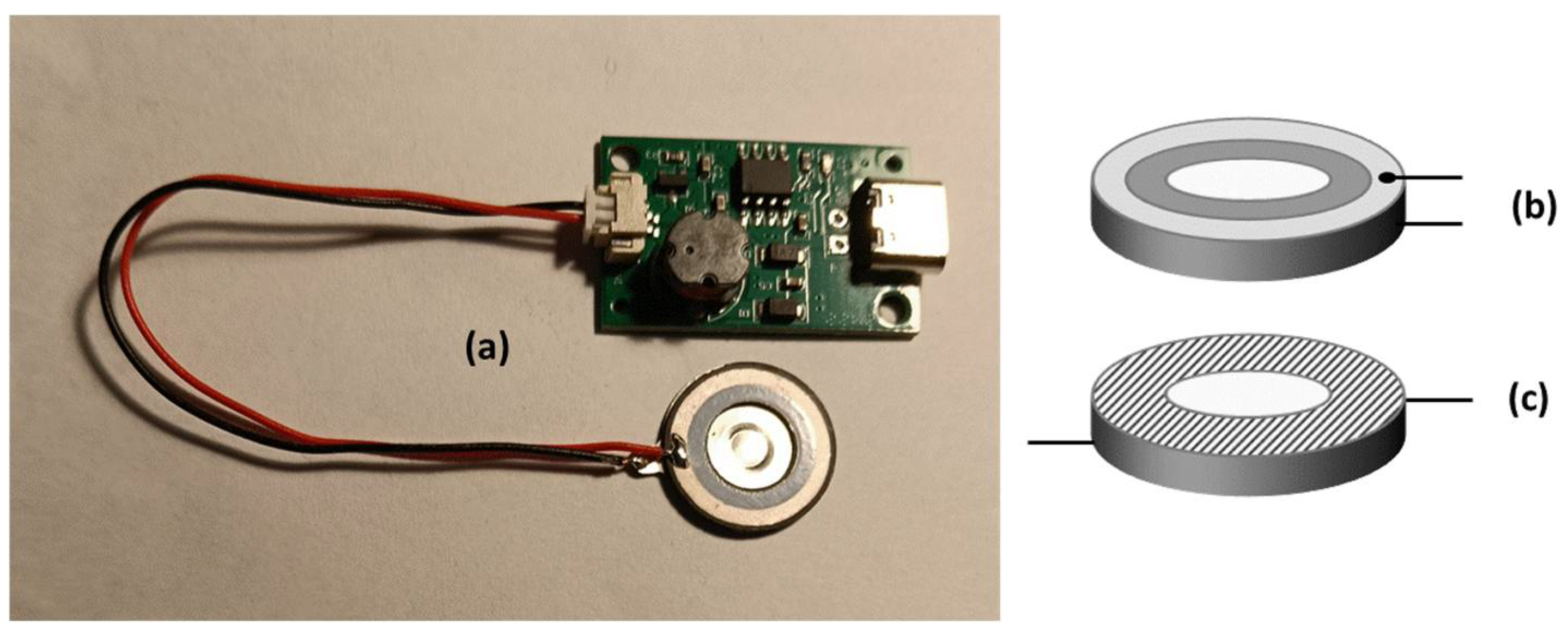
One of the two capacitor armatures has been coated with insulation paint to minimise electrical conduction between the armatures and the liquid drops.
-
The electrical connections between the armatures and the external circuit were redesigned to make them as far apart as possible. This is to avoid possible short circuits between electric terminals, induced by contact with the conductive solution.
-
The driver module of Figure 5a has been mounted on suitable supports connected to heat sinks with forced ventilation, adopting a solution similar to cooling systems for computer CPUs.

3. Results and Discussion

In previous research, Venturi reactors/absorbers have been successfully used in the case of chemical reaction/absorption between a reactant in gaseous form and an absorbent liquid, whether or not it contained another reactant [26]. This is because these types of reactors allow high performance in gas–liquid mixing due to the turbulence of the outgoing mixed flow [27]. They have been recently proposed as a valid solution for CO2 capture [28] and the abatement of pollutants like SO2 and NO from a gas stream [29].
The choice of CaCO3 NP synthesis for the present study has been made for many different reasons. The first motivation is the total absence of toxicity of this inorganic compound [30] and its excellent tolerability for in vivo [31] and in vitro [32] human cells, making it a very promising compound in theranostic nanomedicine [33]. Very recently, CaCO3 NPs have been successfully proposed in nanocomposites as a multi-drug carrier for odontoiatric uses, with interesting results in bone repair and bacterial eradication [34]. Mahmoud et al. [35] synthesised CaCO3 NPs and tested their fire-retardant properties. Furthermore, these inorganic NPs have proven to be efficient nanosorbents for the removal of heavy cations [36], thus representing a viable alternative to biosorbents [37]. Likewise, the process described here can be used for the synthesis of other particles of organic or inorganic composition. The latter include hydroxides, sulfides, or otherwise nanostructured solid phases, provided they are insoluble in the carrier liquid of the Venturi scrubber.
In the experimental campaign realised here, a first attempt was made using the setup described in the left image of Figure 3, namely, adopting an indirect nebulisation technique. However, this choice was affected by a serious drawback that actually hindered its use. In many cases, the atomisation of a saline solution does not imply a significant change in its surface tension ν, with respect to its value in the case of a pure solvent. However, the situation is different in the case of a concentrated solution of electrolytes like Na2CO3. Ozdemir et al. [38] reported a value of ν = 77.15 mN/m at 23 °C for a saturated aqueous solution of Na2CO3, against a value ν = 72.72 mN/m of pure water at the same temperature. This trend, which is different from that of NaHCO3, has been ascribed to the water dipole moment distribution at the air/solution interface [39]. These aspects, owing to a non-tunable power of the atomiser originally designed for diluted solutions of therapeutic use, led to a dramatic loss of aerosolisation efficiency, thus making this setup unusable. For this reason, the indirect ultrasonic aerosolisation was discarded in favour of a direct ultrasonic aerosolisation schematised in the right-hand image of Figure 3, from which all the experimental data reported in this paper were obtained.

3.1. Synthesis by Direct Ultrasonic Aerosolisation and Comparison with Non-Aerosolised Synthesis

In this type of setup, the atomisation of water containing CaCl2 and Na2CO3, each contained in its own atomiser, was carried out under the operating conditions listed in Table 1. Samples were obtained using equimolar concentrations of both reagents in the atomisers, namely C0 = 0.472 M and C0/4 in different experiments.
It has been observed that the sequence of operations for starting the experimental setup must be carried out in a non-invertible order; otherwise, the system will not work. Specifically, the Venturi collector circuit must be started first, followed by switching the gas compressor upstream of the atomisers. The reason for this intriguing phenomenon could be explained by taking into account that the Venturi collector requires that there is no gaseous flow from the nebulisers at plant start-up. Hence, the commissioning of the apparatus described in Figure 1 must be carried out according to the following sequence of operations:
(1)
Start the flow of liquid into the Venturi collector circuit, keeping the air compressor supplying the aerosolizers off.
(2)
Raise the water pressure at the Venturi nozzle inlet by increasing the supply voltage of the liquid pump, up to a value that allows the Venturi nozzle suction to be triggered. Generally, a liquid pressure of 1.5 bar is sufficient and higher values are useless, as they may overload the liquid pump without increasing the effectiveness of NP abatement.
(3)
Turn on the gas compressor and adjust its supply voltage so that the downstream compressor flow rate of gas does not exceed 6 L/min. Higher flow values may interfere with the operation of the Venturi nozzle.
According to the previously described settings, the liquid contained in both aerosolisers is atomised with a flow rate of approximately 9 ÷ 10 cm3/h.
While the system is running, an intense formation of air bubbles is observed in the Venturi vessel. This fact can seriously hamper the operation of the liquid circulation pump, as a mixed gas–liquid phase regime in the pump may give rise to vibrations induced by cavitation phenomena. Consequently, it was necessary to prevent bubble trails from escaping from the Venturi vessel towards the liquid pump. To this end, a glass septum was placed inside it, so that the bubbles do not spread throughout the liquid holdup within the vessel itself, but remain confined to a pre-determined volume, without leaving it. In addition, the vessel was equipped with special devices in the outlet gas piping, including two traps, in order to prevent the entrainment of liquid droplets towards the atomiser compressor.
After an atomisation of 1.5 cm3 of both reagents, the solution inside the Venturi vessel became cloudy, indicative of the formation of a dispersed solid phase of calcium carbonate. Once a volume of 5 cm3 for each reagent has been atomised, the compressor of the aerosolisers was turned off, and so was the circulating pump of the liquid supply to the Venturi nozzle. Finally, a liquid aliquot was extracted from the Venturi vessel in order to characterise its suspended solid phase.
Separately, a CaCO3 synthesis was carried out by impulsively mixing, in a stirred beaker, the same volumes of reagents that were employed in the aforementioned aerosol synthesis (5 cm3 each), injecting them in the same volume V0 of water circulating in the Venturi nozzle circuit. The reagent concentrations were the same as shown in Table 1. This choice was adopted in order to compare the characteristics of particles obtained by two different synthesis processes, but with different mixing modes and, in particular, with different mass confinement. From this point on, AER-1 and AER-2 will indicate the aerosol-mediated synthesis methods using equal precursors concentrations at C0 = 0.472 M and C0/4, respectively, while STR-1 and STR-2 will indicate the stirred-tank synthesis by impulsive injection, in a water volume V0, of the same liquid volumes employed in aerosolisation, each containing the relevant precursor at concentrations C0 and C0/4, respectively. These experimental conditions are summarised in Table 2.
In Figure 6, the lognormal distribution function of the NPs’ diameters by number, measured by DLS, is reported for aerosolised and non-aerosolised CaCO3 synthesis. In the former case, the NPs’ average diameter was 34 nm with a standard deviation of 6 nm, while in the latter case, the average diameter was 52 nm with a standard deviation of 9 nm. The CaCO3 NPs’ average diameter obtained by aerosolisation is significantly smaller than that obtained by a standard mixing in a batch mode, whose solid phase produced cannot be considered nanostructured, as shown in Table 3, where the restrictive convention used by the physicist community is cautiously adopted, assuming that a nanoparticle should have a diameter ≤100 nm. Even more importantly, the polydispersity of particles is considerably limited in the case of aerosolised synthesis with respect to a non-aerosolised one, and this fact is observable by comparison of the standard deviations according to the data reported in the above-mentioned Table 3.
A possible explanation of these results could be given considering the differences in precursor confinement and mixing between the two synthesis techniques. On that theme, Besenhard et al. [40] focused on the role of the reagent flow rate and addition order in the synthesis of Ag- and Au-NPs by a redox technique in a batch reactor, and they found a significant influence of these variables on average particle diameter and polydispersity. On the other hand, micromixing [41] and mass transfer have even greater importance in the microfluidics of open systems, where the droplet reactors [42] are in the hotspot for organic [43] and inorganic NP synthesis [44], including the promising field of Janus particles [45]. A common point between droplet reactor synthesis, emulsion techniques [46] and aerosol-assisted synthesis [47] lies in discretising and confining reagents in mobile microreactors, acting as NPs micro/nanofactories, actually damping particle aggregation. However, nanosynthesis processes in which sprays or aerosolised phases participate can be divided into two categories: those in which nanosynthesis takes place by mutual coalescence between droplets [48] or by mixing of droplets with other phases [49], and those in which it takes place by chemical/physical processes occurring within the droplets themselves and are independent of the above phenomena, as is generally the case for spray/aerosol pyrolysis [50] and for some variants of chemical vapour deposition (CVD) [51]. The present technique belongs to the former category, and hence it is consistent with the related beneficial effects in terms of polydispersity when compared to standard batch processes. The only basic difference with respect to the synthesis method of Fathi et al. [48] lies in the absence of an external energy contribution, as reaction (1) occurs spontaneously at room temperature, being favoured by thermodynamic and kinetic conditions. This fact makes the present method rather uncommon and potentially attractive in terms of inherently safe operation and energy saving, as will be discussed in the next subsection.
In Figure 7, FESEM images of the NP aggregates obtained by direct aerosolisation at two different values of precursor concentration, namely C0 and C0/4, are reported. By simple inspection, the dimension of primary particles is qualitatively consistent with the DLS results.
In Figure 8, the energy-dispersive X-ray spectroscopy has been carried out for the solid phase obtained by the aerosol-assisted method, with reagent concentrations equal to those adopted in Figure 7a. Although the analysis has been carried out up to 20 kV, the horizontal axis has been intentionally cut at a maximum of 10 kV in order to improve the resolution of visible peaks, especially since no other significant peaks were detected for values greater than 10 kV. The presence of Cu is due to the FESEM metal substrate on which the nanostructured phase was deposited, while Na and Cl ions are accessory ions present in both precursors and forming NaCl according to reaction (1). The measured atomic ratio Ca/C = 0.815 is different from the expected value Ca/C = 1, corresponding to a solid phase made of pure CaCO3. This result can be ascribed to an excess of C related to the presence of a thin graphitisation layer deposited on the solid phase to make it conductive, according to the preparatory technique required by FESEM analysis. The composition of the NPs obtained in other experimental configurations proposed here does not differ significantly from those of Figure 8, and hence it has not been reported.

3.2. NP Yield and Related Energy Demand

From the gravimetric measurements, it was determined that the mass of NPs actually obtained by aerosol-mediated synthesis is in the range 33–42% of the mass of aerosolised precursors. A possible explanation of such a phenomenon can be given by recalling that reaction (1), producing a solid phase that is very poorly soluble in water, is almost totally displaced towards the formation of the relevant products and does not influence the NP yield. On the other hand, the latter is strongly affected by fluid dynamic aspects related to duct wall wetting, leading to the formation of unwanted CaCO3 microparticles remaining confined in the duct upstream of the Jet Venturi scrubber, actually reducing the NP yield. However, it should be pointed out that an NP yield not exceeding 42 percent was obtained in the total absence of capping agents, thus representing an infrequent finding in the literature concerning wet chemical methods. In addition, despite the need of improving an overall NP production yield in the perspective of a scale-up transfer, it is important to note that the solid phase abated by the jet Venturi scrubber and circulating in its carrier liquid is almost entirely made up of NPs, as shown by the results presented in Figure 6 and Figure 7, proving a satisfactory selectivity of the collection apparatus.
The processing energy demand for this aerosol-mediated synthesis, taking into account the yield range given above, is estimated to be in the range of 1830–2330 MJ/kg of CaCO3 NPs produced. The energy demand for the production of both reagents (precursors) does not exceed approximately 30 MJ/kg [52], as the energy consumption for Na2CO3 production, according to the Solvay process, can be estimated to be lower than 15 MJ/kg. Namely, the energy consumption for reagents manufacturing in the present study represents only a negligible fraction of the processing energy demand. Intriguingly, approximately 80% of the total impinged energy is dissipated in the Venturi jet scrubber. Wu et al. [53] discussed the cumulative energy demand related to the synthesis of TiO2 NPs according to different production techniques, including reagents and processing energy burden. Although CaCO3 and TiO2 are different chemical species, a few observations can be made. It can be observed that the processing energy demand of the present technique is in line with the corresponding value typical of a biological method and is considerably lower than that required by flame pyrolysis and thermal plasma for titania NP production.

4. Conclusions

A study concerning a synthesis method based on a direct aerosolisation process of two solutions, each containing a reactant, has been proposed. The as-formed NPs, embedded in liquid droplets resulting from the coalescence of two different aerosolised phases, have been captured in a liquid phase by means of a Venturi nozzle. The present experimental technique relies on two closed circuits, namely a liquid phase devoted to NP abatement, and a gaseous phase, carrying two aerosolised liquid phases reacting with each other. The essentials of the present study can be summarised in the following points:
-
The use of two closed circuits, both gas- and liquid-tight, allows minimising NP dispersions in the surrounding environment. For this reason, this technique may be advantageously proposed in the synthesis of toxic or noxious NPs.
-
As a consequence of the previous point, this synthesis process may be carried out in the presence of an inert gas, as a further possible extension of this method, without the need to replace gas leaks. For this reason, the present process may be economically attractive. Additionally, this aspect is of primary importance in the case of reactive NPs, like non-noble metal NPs, often requiring an inert atmosphere.
-
The synthesis of NPs is carried out at room temperature, with positive effects in the synthesis of thermolabile NPs. No additional energy consumption and/or severe experimental conditions were needed, thus fulfilling inherent safety criteria for the process route and operator hazard exposure.
-
This technique allowed obtaining inorganic NPs, avoiding contamination by surfactant or capping agents, usually adopted in wet chemical synthesis. For this reason, the present method lends itself to the production of NPs for theranostic uses, where the presence of additional compounds on the NPs’ surfaces is often undesired.
-
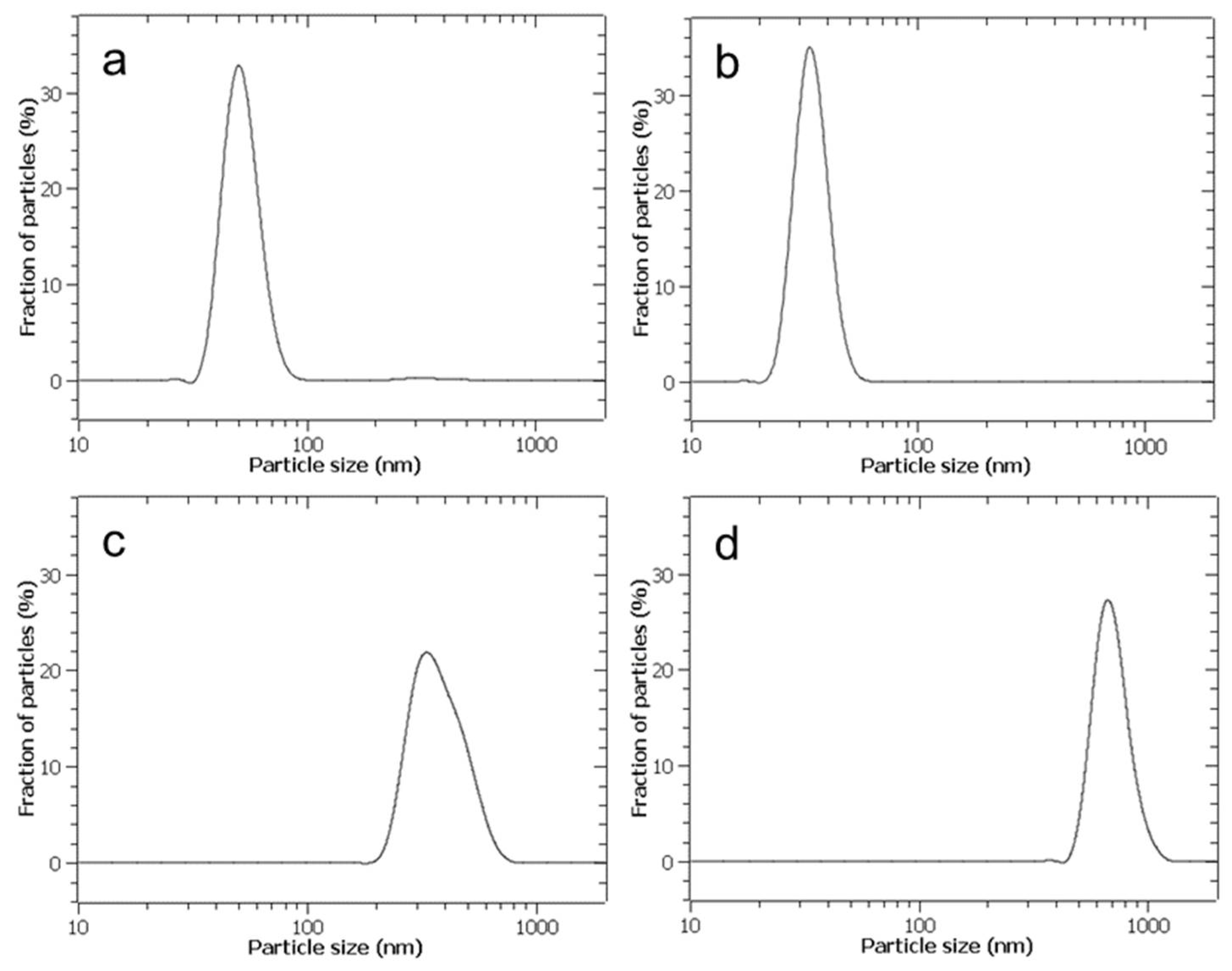
All other conditions being equal, especially in the absence of capping agents, the NPs synthesised here by direct aerosolisation proved to have a diameter dispersion narrower than those obtained by a wet chemical method based on liquid mixing.
As a further development, the present technique will be tested in the synthesis of organic NPs, aiming to achieve inherent safer and sustainable application in nanomedicine.

Author Contributions

All authors contributed significantly and equally to all aspects pertaining to the realisation of the present paper. All authors have read and agreed to the published version of the manuscript.

Funding

This research received no external funding.

Informed Consent Statement

Not applicable.

Data Availability Statement

All data are reported in the paper.

Acknowledgments

The authors wish to thank Alessandra Pesce for the management of the use of the DLS instrument. The authors are grateful, for the FE-SEM characterizations, to the Laboratory of Electron Microscopy-LEM at the Department of Chemistry and Industrial Chemistry at the University of Genoa, Italy.

Conflicts of Interest

The authors declare no conflicts of interest.

References

  1. Pasman, H.J.; Sripaul, E.; Khan, F.; Fabiano, B. Energy transition technology comes with new process safety challenges and risks—What does it mean? Process Saf. Prog. 2024, 43, 226–230. [Google Scholar]
  2. Thirumalaivasan, N.; Gopi, S.; Karthik, K.; Nangan, S.; Kanagaraj, K.; Rajendran, S. Nano-PCM materials: Bridging the gap in energy storage under fluctuating environmental conditions. Process Saf. Environ. Prot. 2024, 189, 1003–1021. [Google Scholar]
  3. Martinelli, A.; Ryan, D.; Sereni, J.; Ritter, C.; Leineweber, A.; Čurlík, I.; Freccero, R.; Giovannini, M. Magnetic phase separation in the EuPdSn2 ground state. J. Mater. Chem. C 2023, 11, 7641–7653. [Google Scholar]
  4. Freccero, R.; Choi, S.H.; Solokha, P.; De Negri, S.; Takeuchi, T.; Hirai, S.; Mele, P.; Saccone, A. Synthesis, crystal structure and physical properties of Yb2Pd3Ge5. J. Alloys Compd. 2019, 783, 601–607. [Google Scholar]
  5. Reverberi, A.P.; D’Addona, D.M.; Bruzzone, A.A.G.; Teti, R.; Fabiano, B. Nanotechnology in machining processes: Recent advances. Procedia CIRP 2019, 79, 3–8. [Google Scholar]
  6. Kulandaivel, S.; Samykano, M.; Keng, N.W.; Rajamony, R.K.; Suraparaju, S.K.; Sofiah, A.G.N.; Kalidasan, B. Nanotechnology revolutionizing heat transfer: A review of nanofluid research and applications. Malays. J. Chem. 2024, 26, 192–210. [Google Scholar]
  7. Rashid, E.U.; Nawaz, S.; Munawar, J.; Sarker, A.; Hussain, S.; Iqbal, H.M.N.; Bilal, M. Organic and inorganic nanoparticles. In Smart Polymer Nanocomposites; Ali, N., Bilal, M., Khan, A., Nguyen, T.A., Gupta, R.K., Eds.; Elsevier: Amsterdam, The Netherlands, 2023; pp. 93–119. [Google Scholar]
  8. Pugazhendhi, A.; Vasantharaj, S.; Sathiyavimal, S.; Raja, R.K.; Karuppusamy, I.; Narayanan, M.; Kandasamy, S.; Brindhadevi, K. Organic and inorganic nanomaterial coatings for the prevention of microbial growth and infections on biotic and abiotic surfaces. Surf. Coat. Technol. 2021, 425, 127739. [Google Scholar]
  9. Sargin, I. Polymer–silver composites for food packaging. In Nanostructured Materials for Food Packaging Applications; Jacob, J., Cacciotti, I., Thomas, S., Eds.; Elsevier: Amsterdam, The Netherlands, 2024; pp. 323–344. [Google Scholar]
  10. Liong, M.; Lu, J.; Kovochich, M.; Xia, T.; Ruehm, S.G.; Nel, A.E.; Tamanoi, F.; Zink, J.I. Multifunctional inorganic nanoparticles for imaging, targeting, and drug delivery. ACS Nano 2008, 2, 889–896. [Google Scholar]
  11. Bhatti, R.; Shakeel, H.; Malik, K.; Qasim, M.; Khan, M.A.; Ahmed, N.; Jabeen, S. Inorganic nanoparticles: Toxic effects, mechanisms of cytotoxicity and phytochemical interactions. Adv. Pharm. Bull. 2022, 12, 757–762. [Google Scholar]
  12. Wu, Z.; Yang, S.; Wu, W. Shape control of inorganic nanoparticles from solution. Nanoscale 2016, 8, 1237–1259. [Google Scholar]
  13. Gaur, J.; Kumar, S.; Pal, M.; Kaur, H.; Batoo, K.M.; Momoh, J.O.; Supreet. Current trends: Zinc oxide nanoparticles preparation via chemical and green method for the photocatalytic degradation of various organic dyes. Hybrid Adv. 2024, 5, 100128. [Google Scholar]
  14. Bigdeli, M.B.; Tsai, P.A. Making photonic crystals via evaporation of nanoparticle-laden droplets on superhydrophobic microstructures. Langmuir 2020, 36, 4835–4841. [Google Scholar] [PubMed]
  15. Kumari, S.; Raturi, S.; Kulshrestha, S.; Chauhan, K.; Dhingra, S.; Andras, K.; Thu, K.; Khargotra, R.; Singh, T. A comprehensive review on various techniques used for synthesizing nanoparticles. J. Mater. Res. Technol. 2023, 27, 1739–1763. [Google Scholar]
  16. Rahli, F.; Chentouf, H.; Terbeche, R.; Chougrani, S.; Djemah, C. Biosynthesis of silver nanoparticles by using Fusarium oxysporum and their therapeutic applications. J. Appl. Nat. Sci. 2022, 14, 1141–1151. [Google Scholar]
  17. Reverberi, A.P.; Vocciante, M.; Salerno, M.; Soda, O.; Fabiano, B. A sustainable, top-down mechanosynthesis of carbohydrate-functionalized silver nanoparticles. React. Chem. Eng. 2022, 7, 888–897. [Google Scholar]
  18. Reverberi, A.P.; Vocciante, M.; Salerno, M.; Ferretti, M.; Fabiano, B. Green synthesis of silver nanoparticles by low-energy wet bead milling of metal spheres. Materials 2020, 13, 63. [Google Scholar]
  19. Chiarioni, A.; Reverberi, A.P.; Fabiano, B.; Dovì, V.G. An improved model of an ASR pyrolysis reactor for energy recovery. Energy 2006, 31, 2460–2468. [Google Scholar]
  20. Banjara, R.A.; Kumar, A.; Aneshwari, R.K.; Satnami, M.L.; Sinha, S.K. A comparative analysis of chemical vs. green synthesis of nanoparticles and their various applications. Environ. Nanotechnol. Monit. Manag. 2024, 22, 100988. [Google Scholar]
  21. Melo, A.A.; Rodrigues, E.P.; Vasconcelos, J.S.; Medeiros, E.S.; Oliveira, L.C.; Lima, A.M.N. Dielectric function of gold nanoparticles synthesized using Camellia sinensis extract. Plasmonics 2023, 18, 529–540. [Google Scholar]
  22. Aliwarga, B.S.; Muhammad, K.; Asri, L.A.T.W.; Wibowo, A. Microwave-assisted synthesis of silver nanoparticles using extract of unbaked cilembu sweet potato. J. Phys. Conf. Ser. 2024, 2866, 012002. [Google Scholar]
  23. Okonkwo, O.; Dhawan, S.; Biswas, P. Controlled synthesis of alumina in a spray flame aerosol reactor. J. Am. Ceram. Soc. 2022, 105, 1481–1490. [Google Scholar]
  24. Zhou, L.; Li, C.; Chen, Y.; Liu, H.; Lin, M.; Duan, J.; Wang, W. Novel Venturi injector reactor design with multiple inlets in ammonia–nitrogen wastewater. Sep. Purif. Technol. 2025, 363, 132062. [Google Scholar]
  25. Mao, S.; Liu, Y.; Zhang, T.; Li, X. Nano-CaCO3 synthesis by jet-reactor from calcium carbide slag. Mater. Res. Express 2020, 7, 115003. [Google Scholar]
  26. Van Dierendonck, L.L.; Zahradník, J.; Linek, V. Loop Venturi reactor-A feasible alternative to stirred tank reactors? Ind. Eng. Chem. Res. 1998, 37, 734–738. [Google Scholar]
  27. Wang, W.; Zhou, L.; Li, C.; Li, G.; Chen, Y.; Pan, Q.; Yu, Z.; Dong, Y.; Duan, J. Novel Venturi injector reactor design and application in ammonia nitrogen wastewater treatment. J. Water Process Eng. 2024, 68, 106352. [Google Scholar]
  28. Huang, R.; Lin, M.; Tian, B.; Xiao, C. A venturi reactor with an excellent mass transfer performance for carbon dioxide capture. J. Environ. Manag. 2024, 360, 121144. [Google Scholar]
  29. Zu, M.; Lin, M.; Huang, R.; Tian, B.; Xiao, C. Mass transfer enhancement for simultaneous desulfurization and denitrification by a venturi reactor. J. Environ. Chem. Eng. 2024, 12, 113216. [Google Scholar]
  30. Tram, N.X.T. Synthesis and characterization of calcite nano-particle derived from cockle shell for clinical application. ASEAN Eng. J. 2020, 10, 49–54. [Google Scholar]
  31. Mosaheb, M.U.F.Z.; Banaszak Holl, M.M.; Tha, K.K.; Abidin, S.A.Z.; Chowdhury, E.H. Fabrication and characterization of calcium carbonate nanoparticles for delivery of doxorubicin in breast cancer cells. J. Drug Deliv. Sci. Technol. 2025, 109, 106979. [Google Scholar]
  32. Nallasamy, P.; Natarajan, S. Folic acid receptor conjugated mesoporous CaCO3 nanoformulation for the therapeutic potential against lung carcinoma. J. Drug Deliv. Sci. Technol. 2024, 92, 105392. [Google Scholar]
  33. Huang, H.; Zhang, W.; Liu, Z.; Guo, H.; Zhang, P. Smart responsive-calcium carbonate nanoparticles for dual-model cancer imaging and treatment. Ultrasonics 2020, 108, 106198. [Google Scholar] [PubMed]
  34. Chen, X.; Bi, J.; Zhang, H.; Yuan, M.; Wang, J.; Hu, N. NIR-responsive CaCO3@ BMP-2/PDA nanocomposite for multifunctional therapy in periodontitis. Colloids Surf. A Physicochem. Eng. Asp. 2025, 713, 136520. [Google Scholar]
  35. Mahmoud, U.M.; Aly, A.A.; Ismail, M.N. Preparing calcium carbonate nanoparticles from biomass waste and its application as fire-retardant agent. Egypt. J. Chem. 2023, 66, 1111–1115. [Google Scholar]
  36. Rezk, R.A.; Abdel-Salam, Z.; Abdel Ghany, N.A.; Abdelkreem, M.; Abdel-Harith, M. LIBS and pXRF validation for the removal of Pb by bio-CaCO3 nanoparticles from contaminated water. SN Appl. Sci. 2022, 4, 151. [Google Scholar]
  37. Beolchini, F.; Pagnanelli, F.; Reverberi, A.P.; Vegliò, F. Copper biosorption onto Rhizopus oligosporus: PH-edge tests and related kinetic and equilibrium modeling. Ind. Eng. Chem. Res. 2003, 42, 4881–4887. [Google Scholar]
  38. Ozdemir, O.; Karakashev, S.I.; Nguyen, A.V.; Miller, J.D. Adsorption of carbonate and bicarbonate salts at the air–brine interface. Int. J. Miner. Process. 2006, 81, 149–158. [Google Scholar]
  39. Du, H.; Liu, J.; Ozdemir, O.; Nguyen, A.V.; Miller, J.D. Molecular features of the air/carbonate solution interface. J. Colloid Interface Sci. 2008, 318, 271–277. [Google Scholar]
  40. Besenhard, M.O.; Baber, R.; LaGrow, A.P.; Mazzei, L.; Thanh, N.T.K.; Gavriilidis, A. New insight into the effect of mass transfer on the synthesis of silver and gold nanoparticles. CrystEngCom M 2018, 20, 7082–7093. [Google Scholar]
  41. Sun, H.; Wu, Y.; Feng, Q.; Qiu, X.; Sun, L.; Yang, H. Rapid in-droplet tri-fluid micromixing and concentration gradient generation for nanoparticle synthesis. Colloids Surf. A Physicochem. Eng. Asp. 2025, 708, 135983. [Google Scholar]
  42. Kašpar, O.; Koyuncu, A.H.; Pittermannová, A.; Ulbrich, P.; Tokárová, V. Governing factors for preparation of silver nanoparticles using droplet-based microfluidic device. Biomed. Microdevices 2019, 21, 88. [Google Scholar]
  43. Amoyav, B.; Benny, O. Controlled and tunable polymer particles’ production using a single microfluidic device. Appl. Nanosci. 2018, 8, 905–914. [Google Scholar]
  44. Park, M.; Kim, S.; Jung, J.H.; Seo, T.S. Synthesis of MoS2 nanoparticles grown on crumpled 3D graphene microballs using a microfluidic droplet generator. Carbon Lett. 2021, 31, 831–836. [Google Scholar]
  45. Saqib, M.; Tufan, Y.; Cemre Orsel, Z.; Ercan, B.; Erdem, E.Y. Biocompatible Janus microparticle synthesis in a microfluidic device. Biomed. Microdevices 2024, 26, 31. [Google Scholar]
  46. Politova-Brinkova, N.I.; Tsibranska-Gyoreva, S.R.; Tcholakova, S.S.; Denkov, N.D.; Danner, T. Preparation of TiO2 nanoparticle aggregates and capsules by the ‘Two-Emulsion Method’. Colloids Interfaces 2020, 4, 57. [Google Scholar]
  47. Debecker, D.P.; Le Bras, S.; Boissière, C.; Chaumonnot, A.; Sanchez, C. Aerosol processing: A wind of innovation in the field of advanced heterogeneous catalysts. Chem. Soc. Rev. 2018, 47, 4112—4155. [Google Scholar]
  48. Fathi, A.; Ahmadi, M.; Madrakian, T.; Afkhami, A.; Asadi, S. A multi-nebulizer-based aerosol-assisted system for the synthesis of magnetic iron mixed metal oxides nanoparticles (MFe2O4, M = Fe2+, Ni2+, Mn2+, Co2+, Zn2+). Chem. Pap. 2023, 77, 6933–6946. [Google Scholar]
  49. Soliwoda, K.; Rosowski, M.; Tomaszewska, E.; Tkacz-Szczesna, B.; Celichowski, G.; Psarski, M.; Grobelny, J. Synthesis of monodisperse gold nanoparticles via electrospray-assisted chemical reduction method in cyclohexane. Colloids Surf. A Physicochem. Eng. Asp. 2015, 482, 148–153. [Google Scholar]
  50. Wang, J.; Meng, Q.; Zhang, Q. Aerosol-assisted synthesis of mesoporous Cu/ZnO–ZrO2 catalyst with highly selective photothermal CO2 reduction to methanol. Dalton Trans. 2023, 52, 6019–6028. [Google Scholar]
  51. Hurain, S.S.; Habib, A.; Hussain, S.M.; Ul-Haq, N. Ultrasound-assisted synthesis of titania nanoparticles, characterization of their thin films, and activity in photooxidation of -β-naphthol. J. Electron. Mater. 2015, 44, 4622–4627. [Google Scholar]
  52. Bhadiyadra, K.; Jong, S.C.; Ong, D.E.L.; Doh, J.-H. Trends and opportunities for greener and more efficient microbially induced calcite precipitation pathways: A strategic review. Geotech. Res. 2024, 11, 161–185. [Google Scholar]
  53. Wu, F.; Zhou, Z.; Hicks, A.L. Life cycle impact of titanium dioxide nanoparticle synthesis through physical, chemical, and biological routes. Environ. Sci. Technol. 2019, 53, 4078–4087. [Google Scholar]
Figure 1. Schematic diagram of the experimental setup. For the sake of clarity, the electric components have not been reported. A and B are the reagents indicated in Equation (2).
Applsci 15 07693 g001
Figure 2. Schematic diagram of the Venturi nozzle adopted for NPs captured in the liquid phase.
Applsci 15 07693 g002
Figure 3. Schematic diagram of two different devices for liquid nebulisation. The left figure refers to an indirect atomization technique, while the right one refers to a direct atomization method. The liquid in the cavity of the indirect aerosoliser has the sole function of transmitting the vibrations produced by a piezoelectric transducer.
Applsci 15 07693 g003
Figure 4. An enlarged photograph of the perforated area, located in the centre of the vibrating plate of the piezoelectric sensor operating via a direct aerosolisation technique.
Applsci 15 07693 g004
Figure 5. (a) A photograph of the driver module, plugged with its piezoelectric transducer, as marketed by the manufacturer. (b) A scheme of the piezoelectric transducer in its original commercial form, with the electric connectors located on the same side of the plate. (c) A scheme of the piezoelectric transducer, specially modified to make it suitable for atomising the conductive solutions used in this work, with the electric connectors placed far from each other. The dashed area represents the surface treated with an insulating paint, specially added here as not foreseen by the manufacturer.
Applsci 15 07693 g005
Figure 6. Plot of particle diameter distribution function obtained by DLS. (a) Direct aerosolisation with CaCl2 and Na2CO3 at concentration C0 = 0.472 [M]. (b) Direct aerosolisation, but with reagent concentrations C0/4. (c) Reagent mixing in stirred tank reactor, with impulsive injection of reagents at concentrations adopted in (a). (d) Reagent mixing in stirred tank reactor, with impulsive injection of reagents at concentrations adopted in (b). Curves are interpolations from frequency histograms derived from averages over three replicate samples, with a maximum experimental error not exceeding 10%.
Applsci 15 07693 g006
Figure 7. FESEM images of CaCO3 NPs obtained by direct aerosolisation. (a) Case with CaCl2 and Na2CO3 concentrations C = C0. (b) The same as (a), but with C = C0/4.
Applsci 15 07693 g007
Figure 8. Plot of EDS analysis of elements detected by FESEM analysis of nanosized phase corresponding to AER-1 sample.
Applsci 15 07693 g008
Table 1. Set of operating conditions adopted for the direct aerosol synthesis. C0 = 0.472 [M].
Setup ComponentSet Value
Venturi vessel total volume1000 [cm3]
Liquid holdup inside the vessel500 [cm3]
Total circulating liquid volume V0600 [cm3]
Maximum liquid holdup in each atomiser20 [cm3]
Liquid pressure at the Venturi reactor inlet1.5 [bar]
Volumetric gas flow rate at a single aerosoliser inlet50 [cm3/s]
Na2CO3 and CaCl2 concentration in aerosolisersC0; C0/4 [M]
Table 2. Summary of key experimental parameters and techniques adopted in the present study.
Sample TypeSynthesis MethodPrecursors Concentrations
AER-1Direct aerosolisation0.472 M
AER-2Direct aerosolisation0.118 M
STR-1Impulsive mixing in stirred tank0.472 M
STR-2Impulsive mixing in stirred tank0.118 M
Table 3. Physical characteristics of the CaCO3 solid phase produced according to different experimental conditions using aerosolised and non-aerosolised synthesis processes.
Sample TypeAverage Diameter (nm)Standard Deviation (nm)
AER-1346
AER-2529
STR-1342 (microparticles)105
STR-2697 (microparticles)118
Disclaimer/Publisher’s Note: The statements, opinions and data contained in all publications are solely those of the individual author(s) and contributor(s) and not of MDPI and/or the editor(s). MDPI and/or the editor(s) disclaim responsibility for any injury to people or property resulting from any ideas, methods, instructions or products referred to in the content.

