

Evaluation of the Effectiveness of Surface Defect Removal by Slide Burnishing


Abstract
1. Introduction
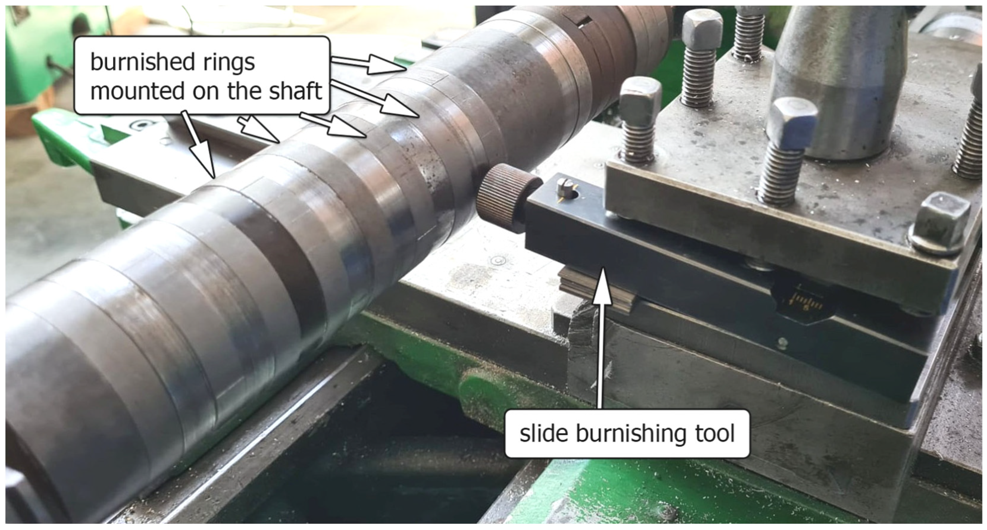
2. Materials and Methods
3. Results and Discussion
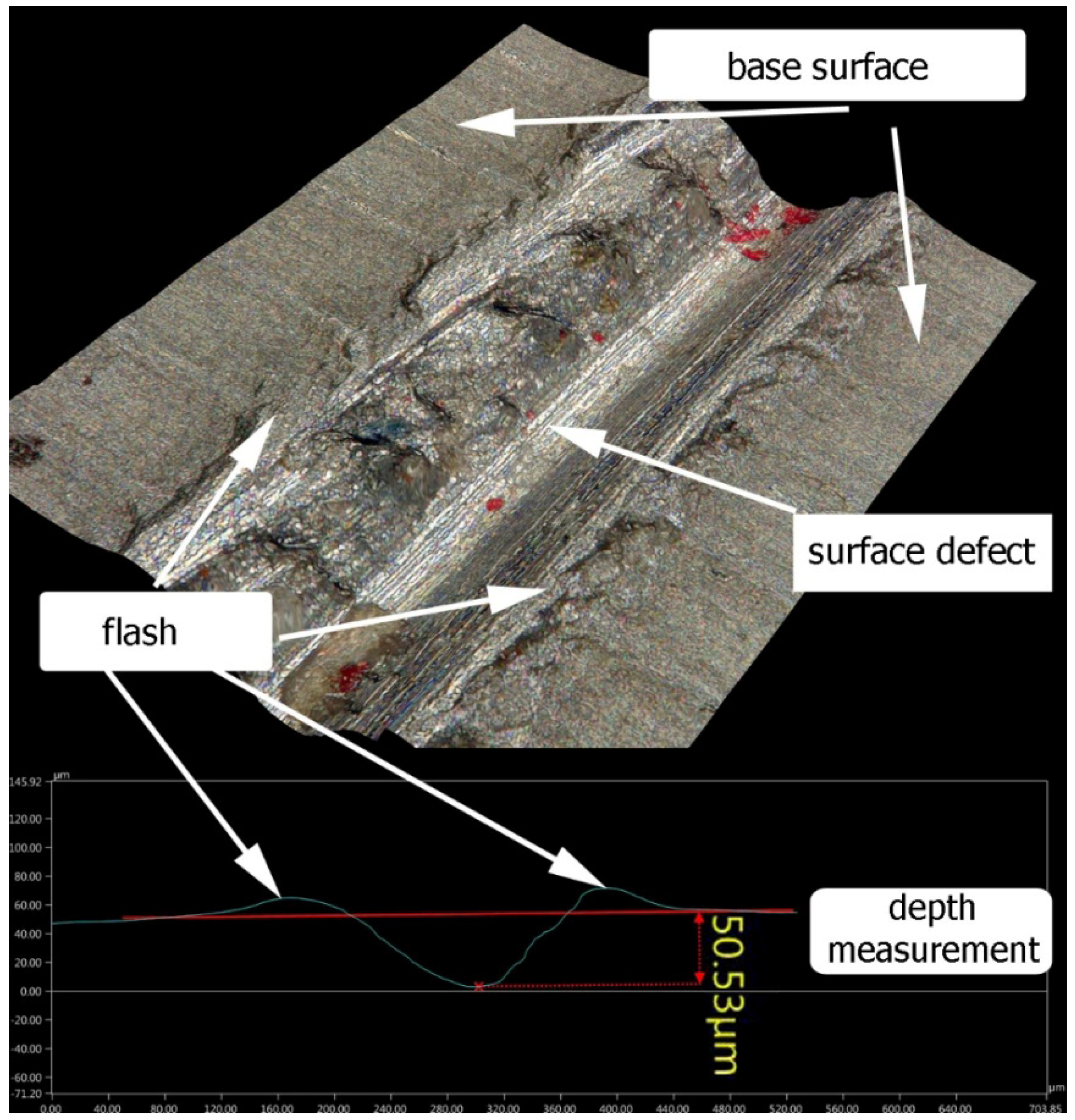
3.1. Visual Defects Analysis Before and After Slide Burnishing
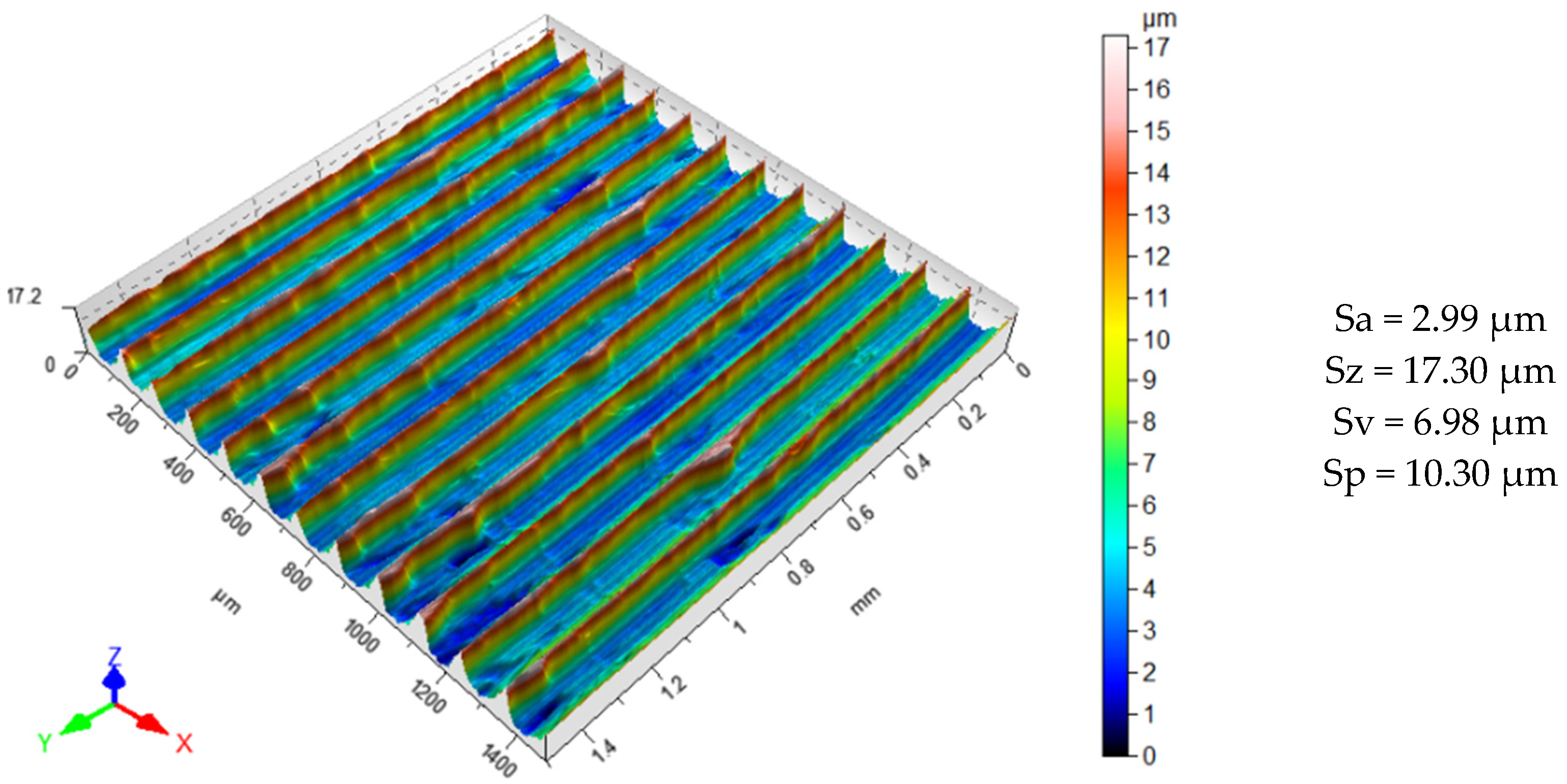
3.2. Surface Topography
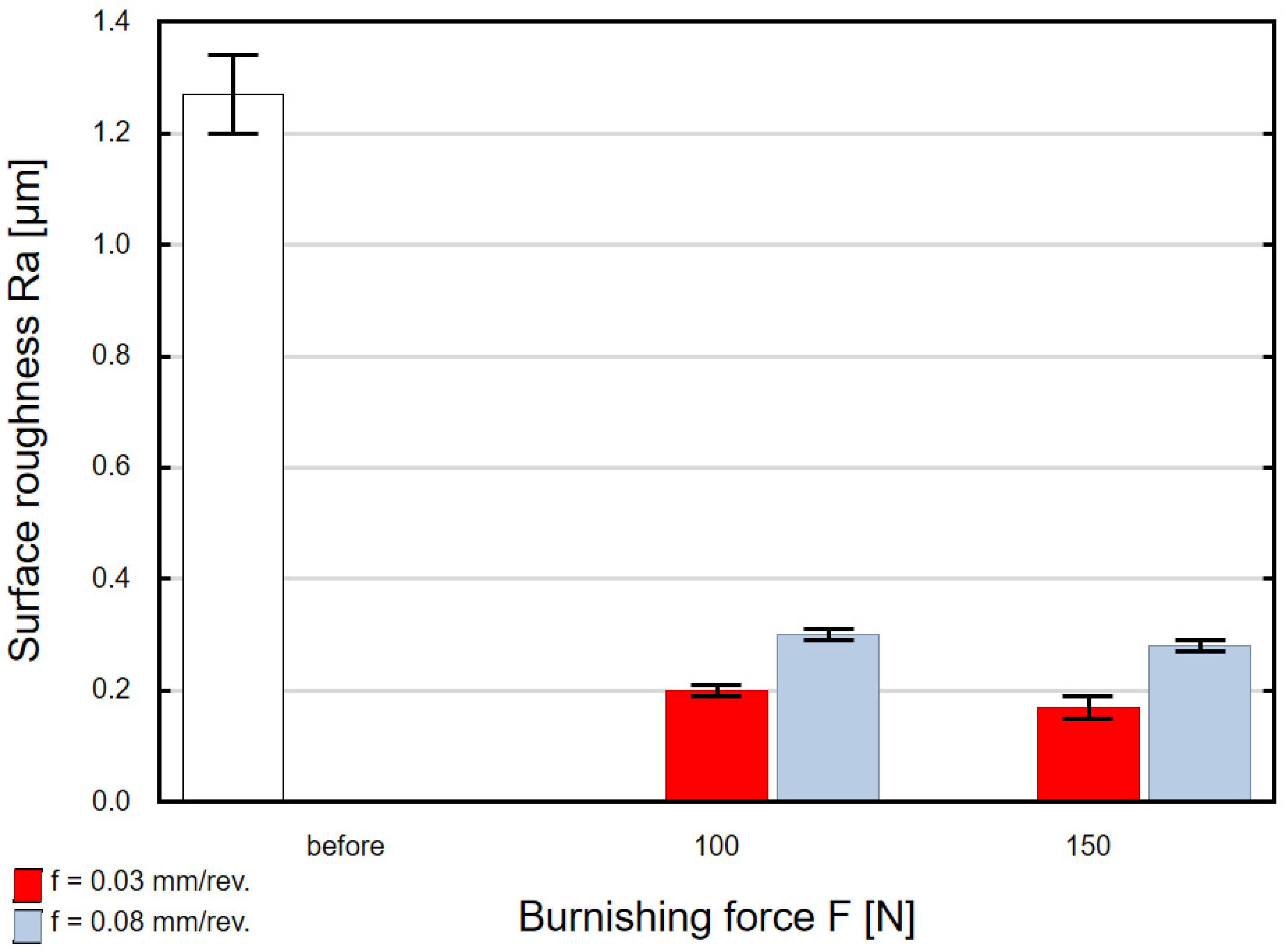
3.3. Surface Roughness
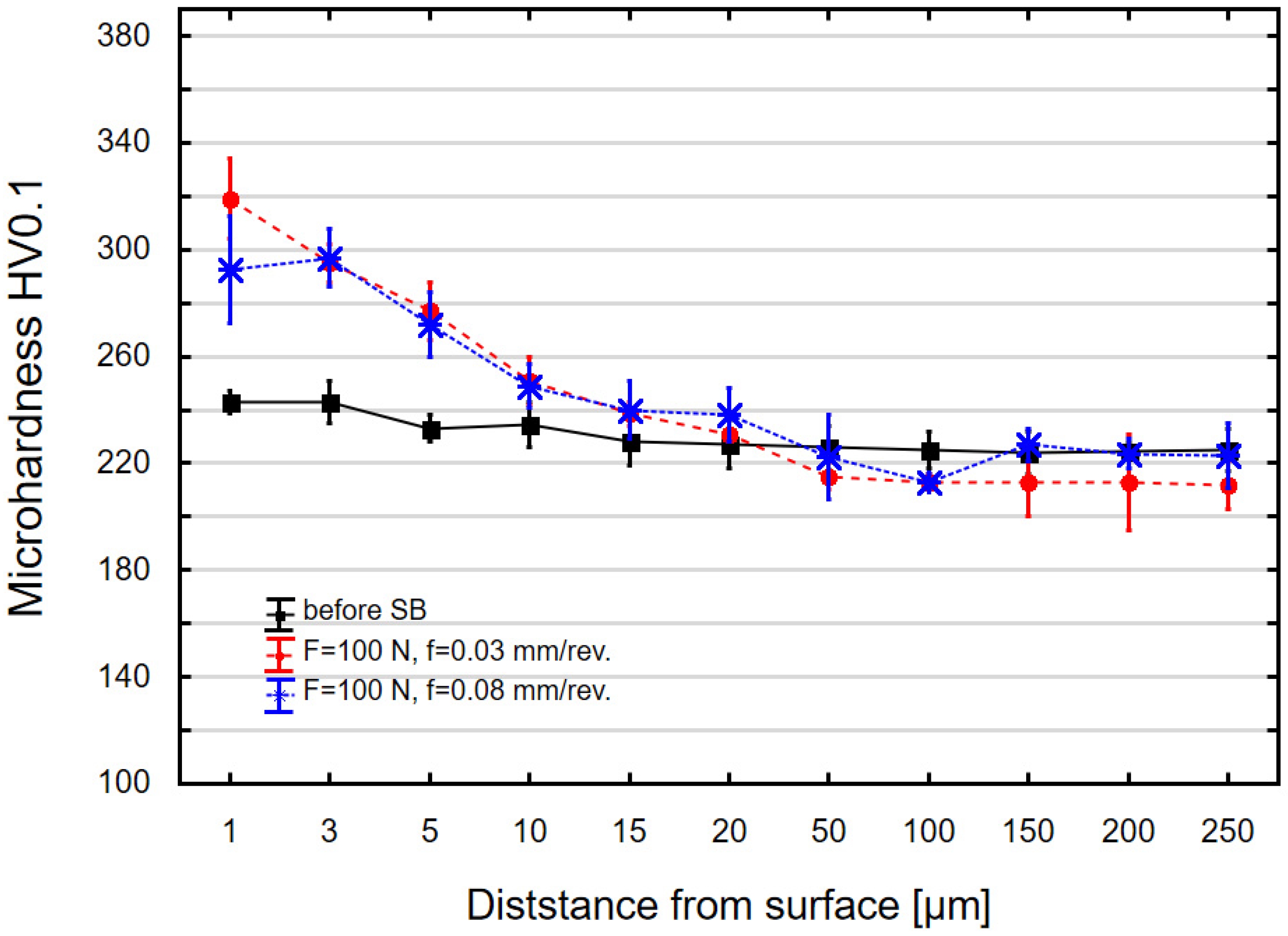
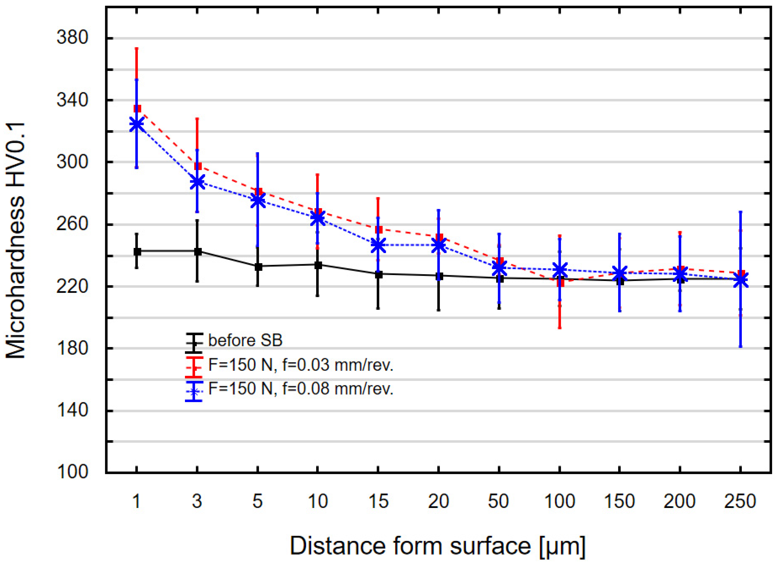
3.4. Microhardness
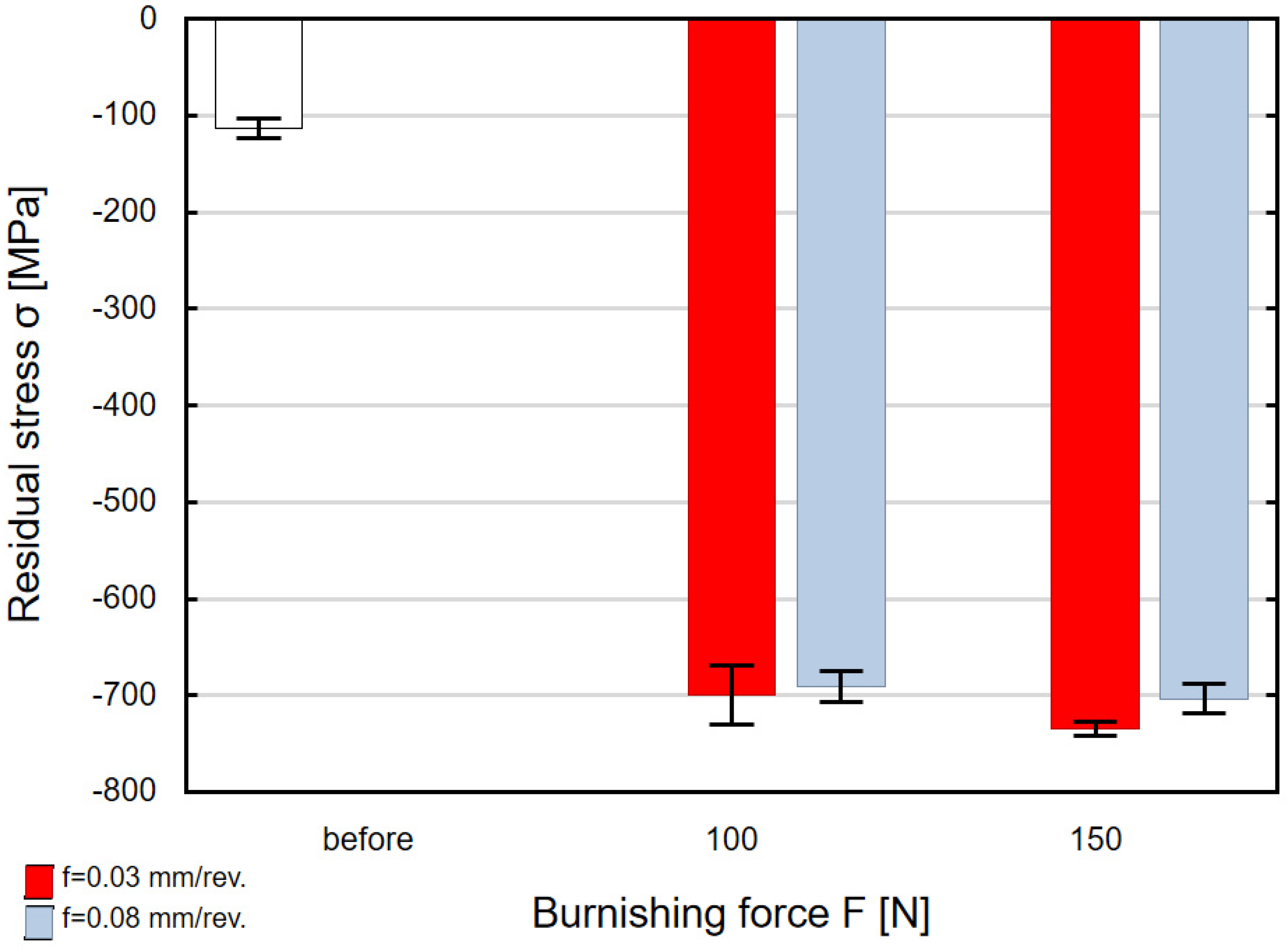
3.5. Residual Stress
4. Conclusions
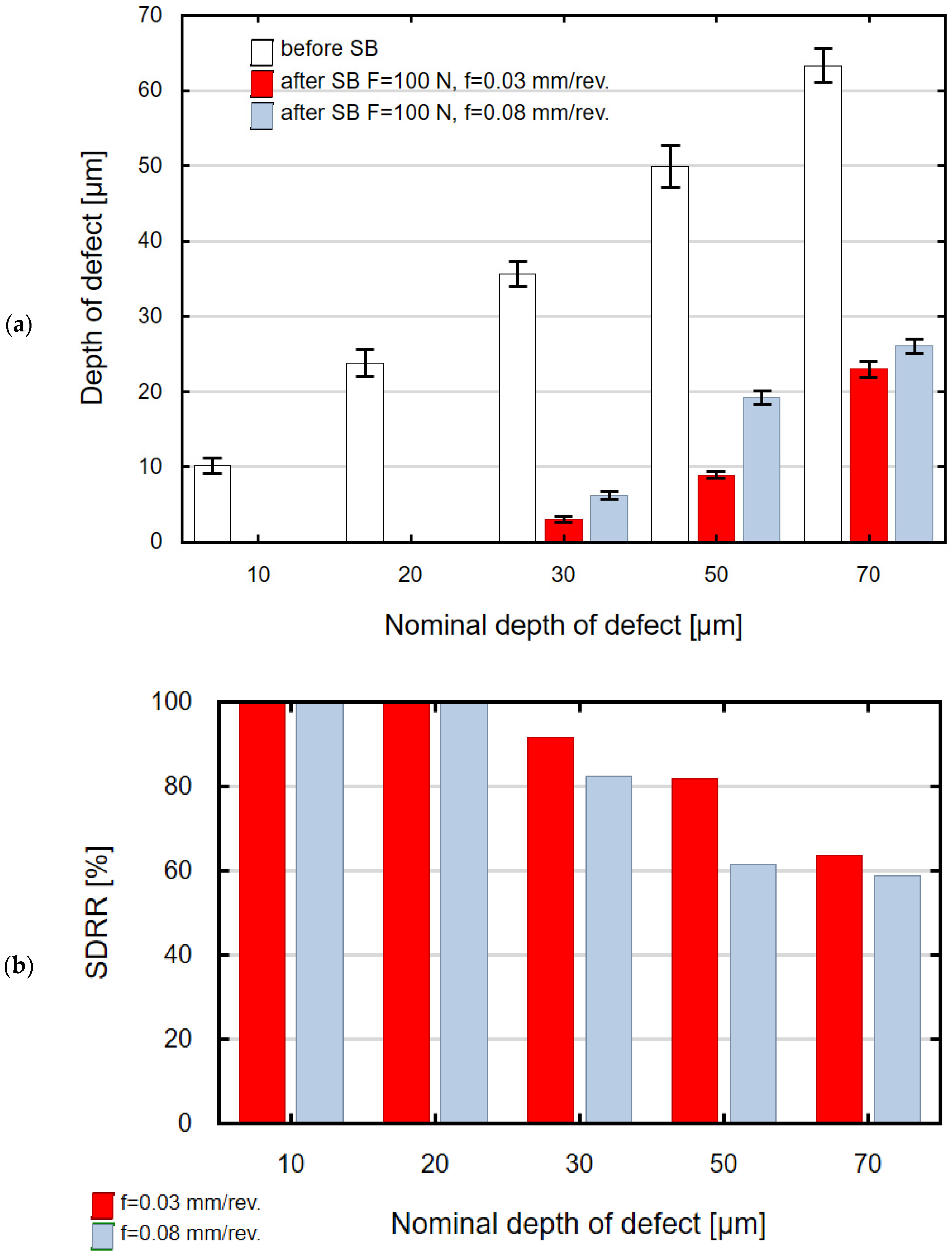
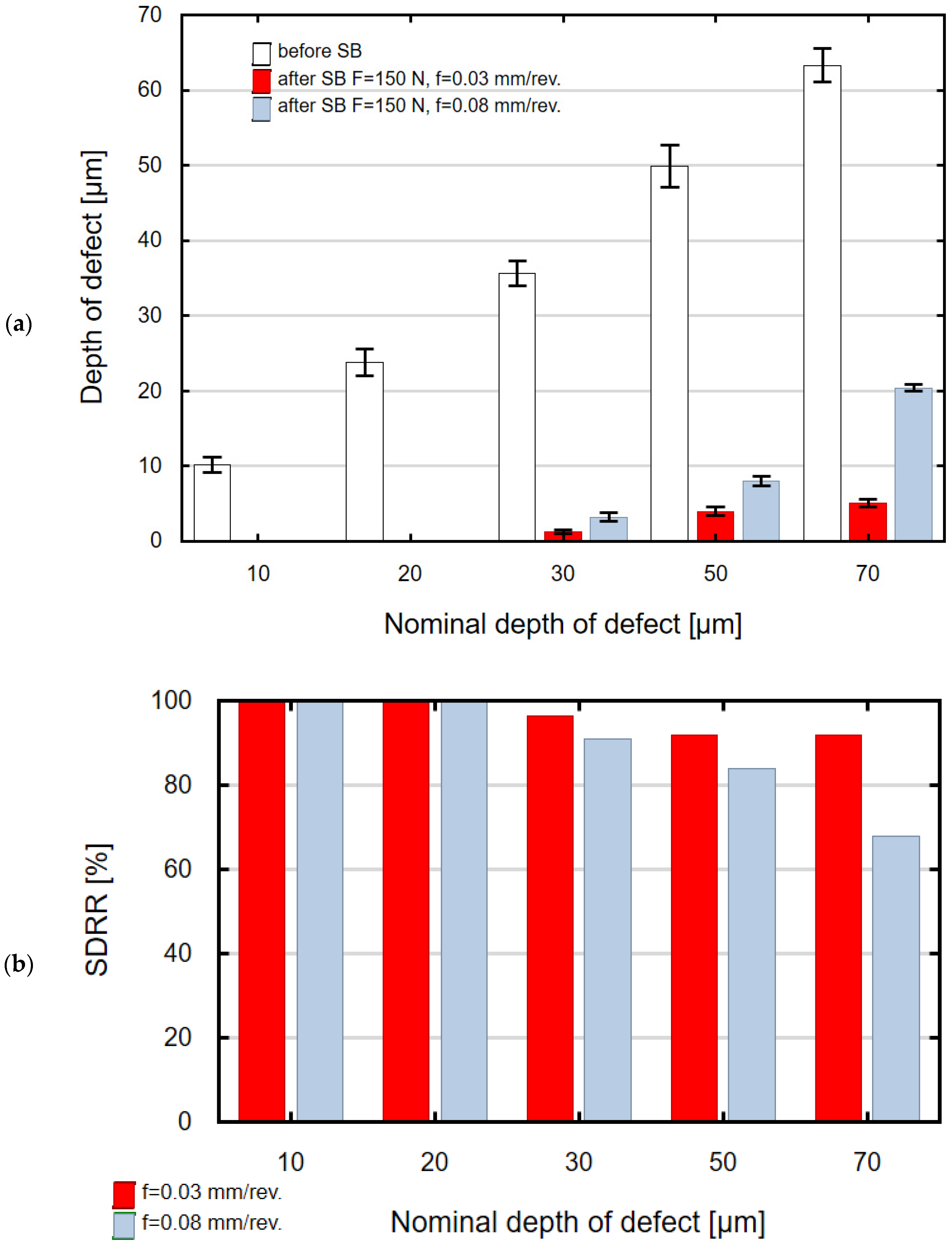
- After slide burnishing, regardless of the applied force F and feed f, scratches with nominal depths of 10 μm and 20 μm were removed.
- For the scratches with their nominal depth ranging from 30 μm to 70 μm after SB, only their depth decreased (it became 2 to 27 times smaller than before slide burnishing).
- The use of slide burnishing changed surface topography. The parameters Sa, Sz, Sp, and Sv decreased.
- After slide burnishing, the parameters of the Abbott–Firestone curve, Ra and Rt, were lower than those after grinding regardless of the SB conditions.
- As a result of the SB treatment, the surface layer was strengthened. The microhardness increased by 20–38% at a depth of 1 μm, and the thickness of the strengthened layer was 10 ÷ 15 μm.
- In the surface layer, just below the slide burnished layer, there occurred compressive residual stresses, the value of which oscillated around σ = −707 ± 19 MPa regardless of the slide burnishing parameters.
- Taking into account the obtained surface layer properties and the effectiveness of “crushing” surface defects on C45 steel samples, it can be stated that the most advantageous effects were obtained when the slide burnishing process was conducted with F = 150 N and f = 0.03 mm/rev.
- Based on the obtained results, it can be assumed that the proposed method of reducing the depth of surface defects will work well in the case of small-depth defects. For large-depth defects, slide burnishing is less effective in reducing them.
Author Contributions
Funding
Data Availability Statement
Conflicts of Interest
Abbreviation
| SB | Slide Burnishing |
References
- Labuda, W.; Wieczorska, A. Possibility of Using the Hydrostatic Burnishing Process under Marine Conditions. Adv. Sci. Technol. Res. J. 2024, 18, 189–205. [Google Scholar] [CrossRef] [PubMed]
- Maximov, J.; Duncheva, G.; Anchev, A.; Dunchev, V.; Anastasov, K.; Daskalova, P. Effect of Roller Burnishing and Slide Roller Burnishing on Surface Integrity of AISI 316 Steel: Theoretical and Experimental Comparative Analysis. Machines 2024, 12, 51. [Google Scholar] [CrossRef]
- Swirad, S.; Pawlus, P. Effect of Ball Burnishing on Fretting at Elevated Temperatures. Materials 2024, 17, 5960. [Google Scholar] [CrossRef]
- Kułakowska, A.; Bohdal, Ł. Surface Characterization of Carbon Steel after Rolling Burnishing Treatment. Metals 2024, 14, 31. [Google Scholar] [CrossRef]
- Maximov, J.; Duncheva, G. The Correlation between Surface Integrity and Operating Behaviour of Slide Burnished Components—A Review and Prospects. Appl. Sci. 2023, 13, 3313. [Google Scholar] [CrossRef]
- Ferencsik, V.; Varga, G. The Influence of Diamond Burnishing Process Parameters on Surface Roughness of Low-Alloyed Aluminium Workpieces. Machines 2022, 10, 564. [Google Scholar] [CrossRef]
- Dix, M.; Posdzich, M. Force-Controlled Burnishing Process for High Surface Integrity on Additive Manufactured Parts. Procedia CIRP 2022, 108, 642–647. [Google Scholar] [CrossRef]
- Korzynski, M.; Dudek, K.; Korzynska, K. Effect of Slide Diamond Burnishing on the Surface Layer of Valve Stems and the Durability of the Stem-Graphite Seal Friction Pair. Appl. Sci. 2023, 13, 6392. [Google Scholar] [CrossRef]
- Dzierwa, A.; Gałda, L.; Tupaj, M.; Dudek, K. Investigation of Wear Resistance of Selected Materials after Slide Burnishing Process. Eksploat. I Niezawodn.—Maint. Reliab. 2020, 22, 432–439. [Google Scholar] [CrossRef]
- Zielecki, W.; Bucior, M.; Trzepiecinski, T.; Ochał, K. Effect of Slide Burnishing of Shoulder Fillets on the Fatigue Strength of X19NiCrMo4 Steel Shafts. Int. J. Adv. Manuf. Technol. 2020, 106, 2583–2593. [Google Scholar] [CrossRef]
- Sachin, B.; Narendranath, S.; Chakradhar, D. Effect of Working Parameters on the Surface Integrity in Cryogenic Diamond Burnishing of 17-4 PH Stainless Steel with a Novel Diamond Burnishing Tool. J. Manuf. Process. 2019, 38, 564–571. [Google Scholar]
- Kato, H.; Hirokawa, W.; Todaka, Y.; Yasunaga, K. Improvement in Surface Roughness and Hardness for Carbon Steel by Slide Burnishing Process. Mater. Sci. Appl. 2021, 12, 171–181. [Google Scholar] [CrossRef]
- Posdzich, M.; Stöckmann, R.; Klimant, P.; Putz, M. Investigation of the Influence of Surface Waviness of Aluminium on the Burnishing Quality of a Combined Process. Procedia Manuf. 2020, 43, 479–486. [Google Scholar] [CrossRef]
- Dezső, G.; Szigeti, F.; Varga, G. Surface Hardness Modification of Selective Laser Melted Ti6Al4V Parts by Sliding Friction Diamond Burnishing. Period. Polytech. Mech. Eng. 2023, 67, 59–69. [Google Scholar] [CrossRef]
- Dyl, T.; Rydz, D.; Szarek, A.; Stradomski, G.; Fik, J.; Opydo, M. The Influence of Slide Burnishing on the Technological Quality of X2CrNiMo17-12-2 Steel. Materials 2024, 17, 3403. [Google Scholar] [CrossRef] [PubMed]
- Nestler, A.; Schubert, A. Effect of machining parameters on surface properties in slide diamond burnishing of aluminium matrix composites. Mater. Today: Proc. 2015, 2, S156–S161. [Google Scholar] [CrossRef]
- Konefal, K.; Korzynski, M.; Byczkowska, Z.; Korzynska, K. Improved Corrosion Resistance of Stainless Steel X6CrNiMoTi17-12-2 by Slide Diamond Burnishing. J. Mater. Process. Technol. 2013, 213, 1997–2004. [Google Scholar] [CrossRef]
- Zhang, W.; Dong, H.; Li, Y.; Yang, C.; Xue, H. Combining Turning with Slide Burnishing to Improve Surface Integrity and Stress Corrosion Resistance. J. Manuf. Process. 2023, 107, 16–33. [Google Scholar] [CrossRef]
- Skoczylas, A.; Zaleski, K.; Matuszak, J.; Ciecielag, K.; Zaleski, R.; Gorgol, M. Influence of Slide Burnishing Parameters on the Surface Layer Properties of Stainless Steel and MeanPositron Lifetime. Materials 2022, 15, 8131. [Google Scholar] [CrossRef]
- Kluz, R.; Antosz, K.; Trzepieciński, T.; Bucior, M. Modelling the Influence of Slide Burnishing Parameters on the Surface Roughness of Shafts Made of 42CrMo4 Heat-Treatable Steel. Materials 2021, 14, 1175. [Google Scholar] [CrossRef]
- Jimenez-García, J.I.; Capilla-Gonzalez, G.; Travieso-Rodriguez, J.A.; Ruíz-Lopez, I.; Balvantín-García, A.J.; Saldana-Robles, A. A Numerical Investigation into the Influence of the Slide Burnishing Process on the Real Surface Roughness and Residual Stress Profiles of AHSS. J. Mater. Res. Technol. 2024, 33, 1406–1419. [Google Scholar] [CrossRef]
- Chodór, J.; Kukiełka, L.; Chomka, G.; Bohdal, Ł.; Patyk, R.; Kowalik, M.; Trzepieciński, T.; Radchenko, A.M. Using the FEM Method in the Prediction of Stress and Deformation in the Processing Zone of an Elastic/Visco-Plastic Material during Diamond Sliding Burnishing. Appl. Sci. 2023, 13, 1963. [Google Scholar] [CrossRef]
- Skoczylas, A.; Kłonica, M. Selected Properties of the Surface Layer of C45 Steel Samples after Slide Burnishing. Materials 2023, 16, 6513. [Google Scholar] [CrossRef] [PubMed]
- Zaleski, K.; Skoczylas, A. Effect of Slide Burnishing on the Surface Layer and Fatigue Life of Titanium Alloy Parts. Adv. Mater. Sci. 2019, 19, 35–45. [Google Scholar] [CrossRef]
- Vasan, V.; Sridharan, N.V.; Vaithiyanathan, S.; Aghaei, M. Detection and Classification of Surface Defects on Hot-Rolled Steel using Vision Transformers. Heliyon 2024, 10, e38498. [Google Scholar] [CrossRef]
- Ashrafi, S.; Teymouri, S.; Etaati, S.; Khoramdel, J.; Borhani, Y.; Najafi, E. Steel Surface Defect Detection and Segmentation using Deep Neural Networks. Results Eng. 2025, 25, 103972. [Google Scholar] [CrossRef]
- Ameri, R.; Hsu, C.-C.; Band, S.S. A systematic review of deep learning approaches for surface defect detection in industrial applications. Eng. Appl. Artif. Intell. 2024, 130, 107717. [Google Scholar] [CrossRef]
- Bai, D.; Li, G.; Jiang, D.; Yun, J.; Tao, B.; Jiang, G.; Sun, Y.; Ju, Z. Surface defect detection methods for industrial products with imbalanced samples: A review of progress in the 2020s. Eng. Appl. Artif. Intell. 2024, 130, 107697. [Google Scholar] [CrossRef]
- Matuszak, J.; Zaleski, K.; Ciecielag, K.; Skoczylas, A. Analysis of the Effectiveness of Removing Surface Defects by Brushing. Materials 2022, 15, 7833. [Google Scholar] [CrossRef]
- Sandell, V.; Nilsson, J.; Hansson, T.; Åkerfeldt, P.; Antti, M.-L. Effect of chemical post-processing on surfaces and sub-surface defects in electron beam melted Ti-6Al-4V. Mater. Charact. 2022, 193, 112281. [Google Scholar] [CrossRef]
- Skoczylas, A.; Zaleski, K. Study on the Surface Layer Properties and Fatigue Life of a Workpiece Machined by Centrifugal Shot Peening and Burnishing. Materials 2022, 15, 6677. [Google Scholar] [CrossRef]
- Maximov, J.T.; Anchev, A.P.; Duncheva, G.V.; Ganev, N.; Selimov, K.F. Influence of the process parameters on the surface roughness, micro-hardness, and residual stresses in slide burnishing of high-strength aluminum alloys. J. Braz. Soc. Mech. Sci. Eng. 2017, 39, 3067–3078. [Google Scholar] [CrossRef]


| No. | Slide Burnishing Force F [N] | Feed f [mm/rev.] |
|---|---|---|
| 1 | 100 | 0.03 |
| 2 | 100 | 0.08 |
| 3 | 150 | 0.03 |
| 4 | 150 | 0.08 |
| Nominal Depth (µm) | Before Slide Burnishing | After Slide Burnishing |
|---|---|---|
| 10 |  | 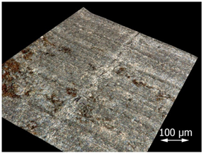 |
| 20 |  | 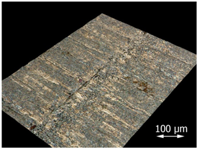 |
| 30 | 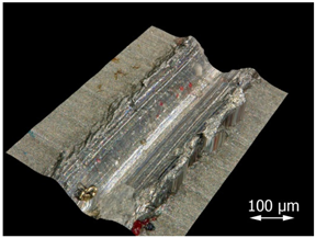 |  |
| 50 | 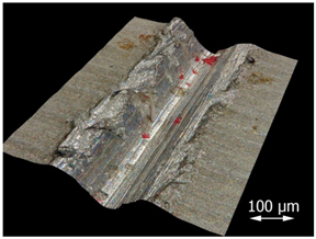 |  |
| 70 | 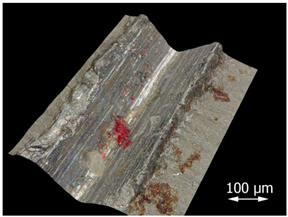 | 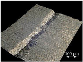 |
| F = 100 N | F = 150 N | |
|---|---|---|
| f = 0.03 mm/rev. | 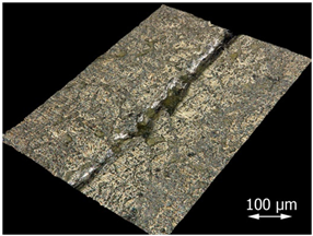 | 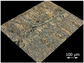 |
| f = 0.08 mm/rev. |  | 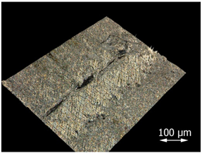 |
| F = 100 N | F = 150 N | |
|---|---|---|
| f = 0.03 mm/rev. | 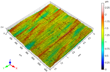 | 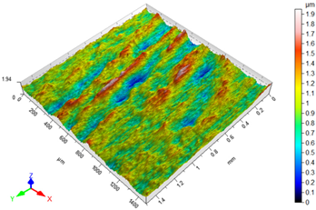 |
| Sa = 0.176 μm; Sz = 2.42 μm Sv = 1.36 μm; Sp = 1.06 μm | Sa = 0.183 μm; Sz = 1.95 μm Sv = 0.955 μm; Sp = 0.994 μm | |
| f = 0.08 mm/rev. | 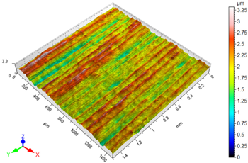 |  |
| Sa = 0.284 μm; Sz = 3.32 μm Sv = 2.02 μm; Sp = 1.30 μm | Sa = 0.285 μm; Sz = 3.88 μm; Sv = 2.24 μm; Sp = 1.43 μm |
Disclaimer/Publisher’s Note: The statements, opinions and data contained in all publications are solely those of the individual author(s) and contributor(s) and not of MDPI and/or the editor(s). MDPI and/or the editor(s) disclaim responsibility for any injury to people or property resulting from any ideas, methods, instructions or products referred to in the content. |
© 2025 by the authors. Licensee MDPI, Basel, Switzerland. This article is an open access article distributed under the terms and conditions of the Creative Commons Attribution (CC BY) license (https://creativecommons.org/licenses/by/4.0/).
Share and Cite
Skoczylas, A.; Zaleski, K.; Matuszak, J. Evaluation of the Effectiveness of Surface Defect Removal by Slide Burnishing. Appl. Sci. 2025, 15, 7398. https://doi.org/10.3390/app15137398
Skoczylas A, Zaleski K, Matuszak J. Evaluation of the Effectiveness of Surface Defect Removal by Slide Burnishing. Applied Sciences. 2025; 15(13):7398. https://doi.org/10.3390/app15137398
Chicago/Turabian StyleSkoczylas, Agnieszka, Kazimierz Zaleski, and Jakub Matuszak. 2025. "Evaluation of the Effectiveness of Surface Defect Removal by Slide Burnishing" Applied Sciences 15, no. 13: 7398. https://doi.org/10.3390/app15137398
APA StyleSkoczylas, A., Zaleski, K., & Matuszak, J. (2025). Evaluation of the Effectiveness of Surface Defect Removal by Slide Burnishing. Applied Sciences, 15(13), 7398. https://doi.org/10.3390/app15137398