Article

Design and Analysis of a Hybrid MPPT Method for PV Systems Under Partial Shading Conditions

by
Oğuzhan Timur
*,† and
Bayram Kaan Uzundağ
Department of Electrical and Electronics Engineering, Çukurova University, Adana 01330, Türkiye
*
Author to whom correspondence should be addressed.
These authors contributed equally to this work.
Appl. Sci. 2025, 15(13), 7386; https://doi.org/10.3390/app15137386
Submission received: 8 May 2025 / Revised: 21 June 2025 / Accepted: 26 June 2025 / Published: 30 June 2025

Abstract

Photovoltaic (PV) power generation may vary with respect to several factors such as solar radiation, temperature, power conditioning units, environmental effects, and shading conditions. The partial shading of PV modules is one of the most crucial factors that causes the performance degradation of PV systems. The main reason for efficiency reduction under partial shading conditions is the creation of multiple local maximums and one global maximum operating point. The classical Maximum Power Point Tracking (MPPT) algorithm fails to determine the global maximum operating point to prevent power losses under partial shading conditions. In this study, a novel hybrid MPPT method based on Perturb & Observe and Particle Swarm Optimization that mainly aims to determine global operating point, is proposed. The proposed hybrid MPPT method is tested under different partial shading conditions and variable irradiance levels. In this manner, the dynamic response of the system is remarkably increased by the proposed MPPT method. To show the superiority of the developed method, a performance comparison is conducted with the P&O- and Kalman-Filter-based MPPT methods. The obtained results illustrate an improvement around 1.5 V in undershoot voltage and 0.2 ms in convergence speed. In addition, the overall system efficiency of the PV system is increased around 2% when compared to the P&O- and Kalman-Filter-based MPPT methods. Consequently, the proposed method seems to be an efficient method in terms of undershoot voltage, convergence time, tracking accuracy, and efficiency under partial shading conditions.

1. Introduction

The usage of renewable energy sources has significantly increased over the past ten years due to reasons such as the dwindling of traditional energy sources, environmental concerns, and the fluctuating price of fossil fuels [1]. One of the most effective and reliable renewable energy sources utilized today is photovoltaic (PV) technology integrated into electrical grids. PV resources are a clean, abundant, economically cheap, and long-term resource that are beneficial to economic development and employment [2,3,4,5]. Solar energy is also one of the most invested-in and promising sources among renewable energy sources. During 2024, around the world, 75% of the expansion in renewable capacity has been caused by photovoltaic energy, and photovoltaic energy capacity has been increased by 30% when compared with the previous year. As of the end of 2024, the total installed solar PV energy capacity worldwide had reached approximately 2.2 TW [6].
A PV system typically consists of PV modules, a controller, a DC-DC converter, and a load [7]. PV modules have two options for powering loads: directly or through DC-DC boost converters. The power transfer capability of a PV system is limited without an MPPT controller. MPPT and DC-DC boost converters can be used to supply the optimum power and adjust the voltage level [8]. Temperature, irradiance, geographic location, panel shadowing, pollution level, humidity, and other factors all have an impact on the solar PV module’s efficiency. Therefore, it is necessary to identify surroundings and employ corrective measures in order to use PV solar energy efficiently [3]. Especially in shading situations, the efficiency of PV cells decreases significantly. The amount of energy that should be produced from the photovoltaic system is lower than desired due to shading [9]. Frequently, trees, poles, snow, chimneys, birds, and antennas provide shade [10,11,12,13,14]. The PV module is forced to work in conditions of partial shade due to the impact of shadows created by nearby objects [15]. In PV systems deployed in urban locations, partial shading is a frequent loss factor that should be taken into account when estimating electrical output [16]. The partial shading phenomena in some PV array modules restrict the total current of the series modules and decrease the overall output power [17]. Partial shade causes a significant drop in the PV array’s power production, which lowers efficiency and raises prices and design complexity. PV panels are typically linked in parallel to boost the power produced or in series to improve string voltage in photovoltaic systems [18,19]. In this situation, shaded PV cells use a portion of the energy produced by non-shaded PV cells if any of these panels are shaded by passing clouds, nearby trees, or other buildings [1]. Maximum Power Point Tracking (MPPT) is used to achieve the desired output power by reducing these negative effects, particularly in partial shading situations.
In the current literature, there are many MPPT algorithms to cope with partial shading conditions and obtain maximum power in PV systems. These MPPT algorithms in the literature are distinguished from each other by various features such as cost, efficiency, implementation complexity, tracking accuracy, tracking speed, required sensors, and input parameters. The Perturb & Observe (P&O) and Hill Climbing (HC) methods are the most widely used methods in the literature [20,21]. These two methods demonstrate a similar core strategy for obtaining the maximum power point (MPP). The HC algorithm works by irregularly changing a power converter’s duty cycle. The P&O algorithm operates with a change in the PV system’s operating voltage [22].
Many other MPPT methods have been used in the literature to solve the partial shading problem. Classical MPPT algorithms have been further developed and are the subject of many studies. Kwan and Wu propose the use of the Lock-On Mechanism MPPT Algorithm, which has been optimized for low oscillation, steady and excellent performance, and adaptive duty cycle ratio measurement [23]. The algorithm, a hybrid Perturb & Observe–Look Up Table Algorithm (LuT), has been proposed by Sulthan et al. and is presented for reacting to quick changes in weather conditions, great efficiency, and accurate and quick MPP tracking [24]. The study by Yüksek and Mete shows the Variable Step Size MPPT Method based on Perturb & Observe-Incremental Conductance Method (IC), which ensures minimal oscillation, quick MPP tracking, and dynamic step size [25]. In contrast to traditional MPPT methods, Irmak and Guler present Perturb & Observe and the Model Predictive Control (MPC) MPPT algorithm, which has the features of good performance, quick response time, control without a comparison structure, and a successful efficiency ratio [26]. In the study by Lemmassi et al., a system based on Perturb & Observe and Incremental Conductance MPPT algorithms for Cube Satellites with low implementation cost, increased MPP tracking accuracy, easy-to-apply MPPT, and adaptability to environmental changes was proposed [27]. A hybrid Fractional Short Circuit Current (FSCC) and Perturb & Observe MPPT algorithm was designed by Sher et al. to enhance quick environmental change adaption, quick MPP monitoring, and high efficiency and to provide a steady state without the need for an irradiance sensor or intelligent weather forecasting [28]. Shetty and Sabhait have demonstrated that a hybrid Grey Wolf Optimization (GWO) and Incremental Conductance MPPT algorithm, which minimizes torque swing, quickly reaches MPPT, enhances excellent efficiency, and quickly reacts [29]. The Shuffled Frog Leaping Algorithm (SFLA)–Incremental Conductance hybrid MPPT method, the algorithm proposed by Chiue and Ngo, has been implemented to provide the system with reliability, low computational time, and low computational complexity [30]. Kacimi et al. present a novel hybrid MPPT algorithm based on Neural Network, Model Predictive Control, and Kalman Filter, which has great performance in terms of efficiency, oscillations, MPP tracking accuracy, MPP tracking speed, overshoots, and output power [31].
Various methods combining many MPPT algorithms continue to be developed in the literature. According to the article by Basinski et al., a hybrid Stochastic Evolutionary Search-Specific Hill Climbing MPPT algorithm has been shown to provide cheap implementation costs and little computing complexity [32]. Assam et al. presented a new hybrid Backstepping-Sliding Mode MPPT algorithm, which has been developed to provide strong performance, low overshoot, and reduced oscillation [33]. Rizzo and Scelba highlight the features of a Hybrid Two-Stage Global Maximum Power Point Tracking Algorithm in terms of energy saving, fast response, and adaptability to changing conditions [34]. In the work of Ghosh, the Improvised Binary Sequence–Perturb & Observe hybrid MPPT algorithm has been proposed, which has quick reaction time, adaptability, and precise MPP tracking [35]. Tao et al. present a new hybrid method referred to as Whale Optimization (WO)–Pattern Search Algorithm based on ANFIS, which had good results in terms of excellent power output, effective MPP tracking, and high efficiency outcomes [36].
Some methods include evolutionary algorithms and nature-inspired optimization algorithms. Hassan et al. introduce the Genetic Algorithm (GA)-Based Fractional Open Circuit Voltage (FOCV) MPPT algorithm, which enhances rapid MPP tracking, has excellent efficiency, and decreases voltage swing [37]. The Hybrid Differential Evolution (DE)–Feed Forward Neural Network MPPT Algorithm, as introduced by Ncir et al., has been made to provide a high effectiveness level, a quick tracking capability, and high MPP precision [38]. The ANFIS-based hybrid Crow Pattern Search (CPS)–Incremental Conductivity Algorithm is proposed by Ahmed et al., pointing to minimized power ripple, high efficiency, higher output power, and a low sampling rate [39]. In the work of Hilali et al., an MPPT algorithm based on the Bat Metaheuristic Optimizer has been proposed, where the MPP tracking error is reduced, the MPP tracking speed is increased, the response time to changing irradiance conditions is reduced, the MPP tracking oscillation performance is significantly improved, the pump water flow rate of the proposed system is increased, and the solar water pump system is made more efficient [40]. In the work of Mohanty et al., a hybrid Gray Wolf Optimization and Perturb & Observe MPPT algorithm was proposed, which has the features of fast and precise MPP tracking with a high tracking rate [41]. Chao and Rizal proposed a hybrid MPPT algorithm using the Genetic Algorithm and Ant Bee Colony Optimization, which has been optimized for high MPP accuracy, a fast calculation speed, and few calculation steps [42]. In the work of Salim et al., a hybrid Cuckoo Search (CS) and Gray Wolf Algorithm was designed, with rapid MPP tracking, zero oscillation in a constant state, more effectiveness than GWO, and good dependability [43]. Elymany et al. presented a system based on ANFIS using the Zebra Optimization Algorithm and the Artificial Gorilla Troops Optimization Algorithm, which has the features of good performance, quick computing time, and effective hybrid design [44].
In some studies, algorithms using machine learning and artificial intelligence were developed. Nabipour et al. propose a new Adaptive Fuzzy Logic Controller MPPT method, which provided improved tracking performance, increased performance, and reduced active power ripple [45]. The study by Rizzo et al. shows that a hybrid Artificial Neural Networks (ANN) and Hill Climbing MPPT algorithm is capable of flexibility in response to changing conditions, minimal processing demands, and no necessity for more equipment [46]. In the study by Padmanaban et al., the ANFIS-Ant Bee Colony Hybrid MPPT algorithm was proposed, providing a low rate of harmonic distortion, safe grid connection, quick reaction, high efficiency, and precise MPP tracking [47]. A hybrid MPPT algorithm based on the Perturb & Observe—Artificial Neural Networks algorithm was introduced by Çelik and Teke, which provides a high power factor, low harmonic distortion, accurate MPP tracking, low oscillation in steady state, quick MPP tracking, high efficiency, and irradiance condition adaptation [48]. A hybrid MPPT method based on MSFLA and the Fuzzy Logic Controller (FLC) was proposed by Li et al.; it has consistent reliable MPP, high effectiveness, high power output, quick MPP tracking, and the integration of battery energy storage [49]. In a work by Priyadarshi et al., a hybrid MPPT algorithm based on ANFIS—Particle Swarm Optimization was proposed, providing fast and precise MPP tracking, zeta converter integration, minimal harmonic distortion, quick computation times, and no need for extra sensors [50]. In the study by El Mezdi et al., an MPPT method based on Artificial Neural Networks was proposed, which uses only current and voltage measurement, can track the reference voltage stably, has a low error rate, can respond quickly to changes, and provides stable operating conditions [51].
Innovative methods are also being developed in MPPT studies. The study by Ge et al. shows that a new MPPT method based on the Bat Algorithm and Fuzzy Logic Controller has the features of high efficiency, the integration of the grid and batteries, a quick reaction time, minimal oscillation, fit for the application, and precise and high MPP tracking [52]. Pradhan et al. presented the Modified Invasive Weed Optimization—Perturb & Observe hybrid MPPT algorithm, aims to provide a minimal voltage ripple, is grid-compatible, and can track MPP well [53]. In an article by Balaji and Fathima, a hybrid Salp Swarm Algorithm (SSA) and Perturb & Observe MPPT method was developed, which has faster MPP tracking, a low oscillation rate, adaptability to changing circumstances, application compatibility, and the need for only one sensor [54]. In a study by Eltamaly, a new Musical Chair MPPT algorithm was developed; it provides high performance, quick computing time, minimal steady-state volatility, and accurate MPP monitoring [55]. The Modified Krill Swarm Algorithm and Fuzzy-Logic-Controller-based MPPT design, presented in the work of Hu et al., found a quick and precise reaction to changing irradiance circumstances and dependable power source [56].
Many studies in the literature have been examined, and, in summary, various features have been investigated. The merits and demerits of MPPT methods in the current studies in the literature are given in Table 1.
There are many studies in the literature that address the partial shading problem in PV arrays. However, there is still a gap that need to be filled for the accurate detection of the maximum operating point under partial shading conditions. In addition, convergence time, tracking accuracy, and undershoot voltage rate issues under rapidly changing irradiance levels seem to be significant performance parameters that need to be improved. In this context, a hybrid MPPT method based on Perturb & Observe and Particle Swarm Optimization is proposed to determine the global maximum power point under partial shading conditions. The proposed hybrid MPPT method is tested under different partial shading conditions and rapidly changing irradiance levels. The obtained results reveal that the dynamic response of the system is remarkably increased by the proposed MPPT method. Moreover, the maximum operating point is accurately determined to obtain the maximum power for partial shading conditions. The main contributions of this study are listed as follows;
  • The dynamic response of the system is remarkably improved for rapidly changing irradiance levels,
  • Maximum operating point determination capability of the developed algorithm is high when compared to existing methods in the current literature,
  • The number of oscillations under steady-state operation is significantly reduced,
  • The accuracy of the perturbation direction is increased by the proposed method.
The proposed method seems to be a promising method in terms of reduced undershoot voltage, improved convergence time, and increased tracking accuracy under partial shading conditions.
The rest of the paper is organized as follows. In Section 2, the characteristics of the PV system, which is created in MATLAB (version R2016b)/Simulink environment, are mentioned. In Section 3, the features of the simulation scenarios are discussed. In Section 4, the purpose of the study, the method of the study, and the characteristics of the PV system are discussed. Finally, in Section 4, the study results are given and the outputs are interpreted.

2. Materials and Methods

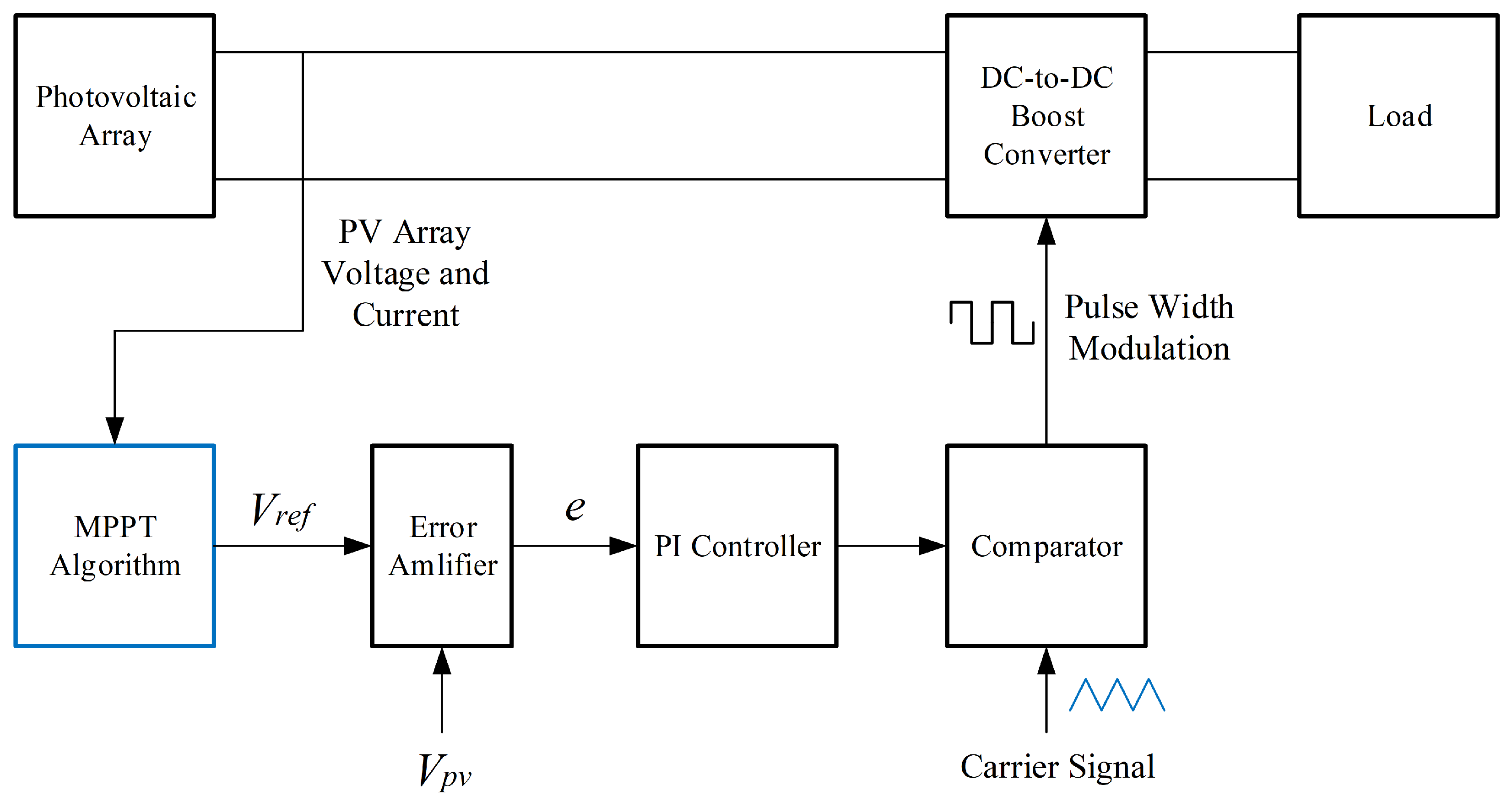
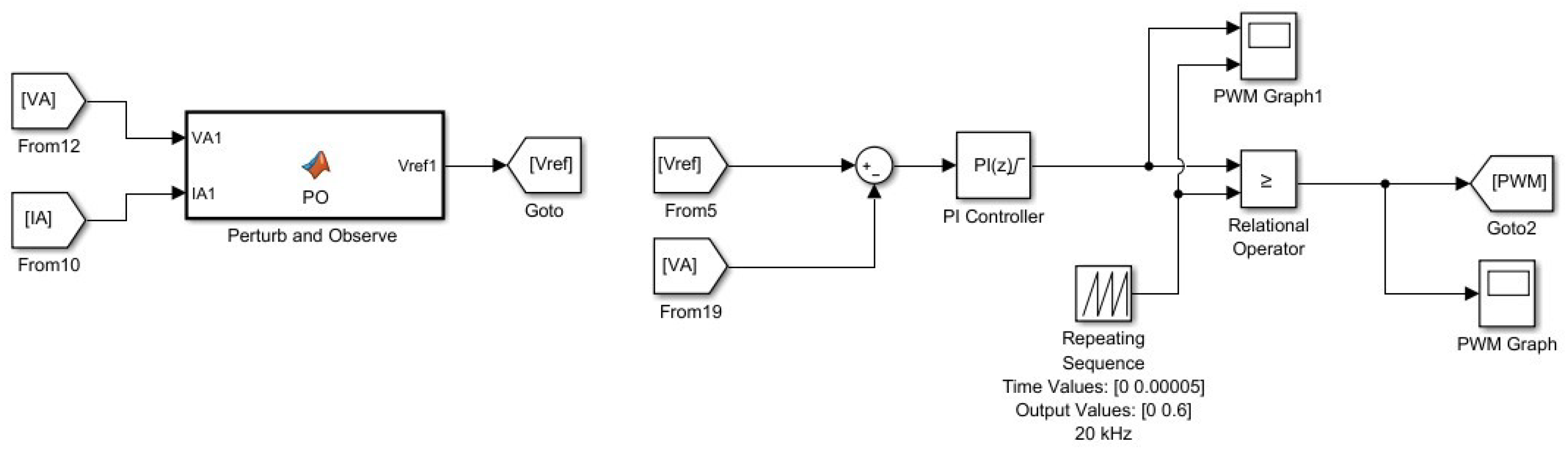
2.1. Design of the Proposed PV System

A solar energy system using the proposed Perturb & Observe and Particle Swarm Optimization hybrid-based MPPT algorithm has been developed in the MATLAB/Simulink environment. The system consists of a solar panel array, a DC-DC boost converter, and DC-DC boost converter control circuit sections.
In a PV system, the voltage and current values produced from the PV array are measured. The measured voltage and current values are used by the MPPT algorithms. The determined MPPT algorithms are prepared as MATLAB code in the MATLAB Function block. At this stage, MPP tracking is performed, and the function produces a reference voltage. This voltage is transmitted to the DC-DC boost converter control circuit. The error between the reference voltage and the PV array voltage is detected. This error signal is processed by the Proportional-Integral (PI) controller and then transmitted to the comparator. Here, a comparison process is made with the triangle wave signal, and a switching signal is produced at the output. Lastly, the switching element on the DC-DC boost converter is operated with switching signal, which is named Pulse Width Modulation (PWM) signal. DC voltage generated in the PV array is increased using this switching signal. The block diagram of the implemented PV system is shown in Figure 1.

2.2. Design of DC-DC Boost Converter

A DC-DC boost converter has been used in the PV system created for simple, fast, and reliable power transfer and voltage increase. The DC-DC boost converter has a structure consisting of five parts. These are the inductor, capacitor, diode, switching element, and output resistor. Generally, IGBTs (Insulated-Gate Bipolar Transistors) are used for switching. In this part of the system, the PV array is connected to the DC-DC boost converter through a parallel connected capacitor in the middle. This capacitor is used to correct the input voltage imbalance and reduce voltage fluctuations. The input capacitor value of 1 mF was selected. The characteristics of PV array used in the design are given in Table 2.
In this simulation, IGBT is used for switching for the DC-DC boost converter. In this designed system, a PV Array output voltage of 346.71 V was selected. This value is the input voltage of the DC-DC boost converter. The DC voltage is increased by this DC-DC boost converter and 540 V DC voltage is obtained at the output. A switching frequency of 20 kHz was selected. The parameters used in designing the DC-DC boost converter are shown in the equations below [57,58].
The output current of the converter is shown below in Equation (1).
I o u t = P o u t V o u t = 11,760.40 W 540 V = 21.78 A
The load resistor value of the converter is shown below in Equation (2).
R L = V o u t I o u t = 540 V 21.7785 A = 24.79 Ω
The duty cycle of the converter is shown below in Equation (3).
D = 1 V i n V o u t = 1 346.71 V 540 V = 0.3579 = 35.79 %
The voltage ripple of the converter is shown below in Equation (4).
Δ V out = 0.01 × 540 V = 5.4 V
The current ripple of the converter is shown below in Equation (5).
Δ I out = 0.1 × 21.78 A = 2.18 A
The capacitor value of the converter is shown below in Equation (6).
C = I o u t × 1 V i n V o u t f s w × Δ V o u t = 21.78 A × 1 346.71 V 540 V 20 kHz × 5.4 V = 72.18 μ F
The inductor current ripple of the converter is shown below in Equation (7).
Δ I L = 0.01 × I o u t × V o u t V i n = 0.01 × 21.78 A × 540 V 346.71 V = 0.34 A
The inductor value of the converter is shown below in Equation (8).
L = V i n × V o u t V i n f s w × Δ I L × V o u t = 346.71 V × 540 V 346.71 V 20 kHz × 0.34 A × 540 V = 0.018 H
The values obtained from the calculations of the DC-DC boost converter are shown in Table 3.
The DC-DC boost converter in the designed circuit is shown in Figure 2. The switching element of the DC-DC boost converter control circuit receives the reference voltage coming from the MATLAB function block that runs the MPPT algorithm. Then an error is generated from this reference voltage with the measured voltage of the PV array. This error reaches the Proportional-Integral (PI) controller. The signal from the PI controller output is compared with the 20 kHz triangle wave. As a result, the Pulse Width Modulation (PWM) signal that will trigger the switching element is generated. Figure 3 shows an example DC-DC boost converter control circuit.

2.3. Design of the Proposed MPPT Algorithms

In this article, three different MPPT methods, including the proposed method, have been examined and compared. The first of these is the Perturb & Observe algorithm, known as a traditional algorithm, which stands out for its simple design and ease of implementation. Due to its small number of parameters, fast MPP tracking ability, and better performance in low-hardware systems, it is frequently included in studies in the literature, and the P&O MPPT algorithm has been selected as the fundamental algorithm in this study. Kalman Filter–Perturb & Observe Hybrid MPPT is a method that was created by combining the computational logic of the traditional P&O MPPT method with the Kalman Filter, which is a model- and estimation -based algorithm. In addition to the aforementioned advantages of P&O, it provides a faster and closer approach to the MPP point with its estimation ability and noise reduction ability. It processes data from voltage and current sensors and increases the MPPT ability of the P&O algorithm by calculating the estimated power. An improved hybrid algorithm has been tested by selecting the KF-P&O Hybrid MPPT method as the secondary method. In this study, a hybrid method combining the P&O algorithm and the PSO algorithm is proposed. In this hybrid method, the P&O algorithm determines the reference voltage quickly and approaches MPP. Then, the MPP is determined more accurately by using the PSO algorithm. By choosing the PSO algorithm which has the logic of algorithm inspired by nature and P&O algorithm, which is the classical method, two different algorithms that are in different categories are used. The P&O-PSO Hybrid MPPT method is chosen as the proposed method due to features such as less parameter adjustment, faster MPP convergence, high MPP tracking accuracy and ability to select global maximum search range depending on parameters.
In this section, MPPT algorithms are used with function blocks in the MATLAB/Simulink environment. Each function block contains the MATLAB code containing the relevant algorithm. The MPPT algorithms are hybrid in structure and are created by combining more than one MPPT algorithm. In these function blocks, MPP tracking is performed, and Vref, which is the reference voltage at the outputs, is produced. The reference voltages generated here are then be sent to the DC-DC boost converter control circuit. Then the current and voltage values of the PV array are measured in this structure. The measured values are processed with the MPPT algorithm and a reference voltage is produced as a result. This reference signal is used for the DC-DC boost converter control.

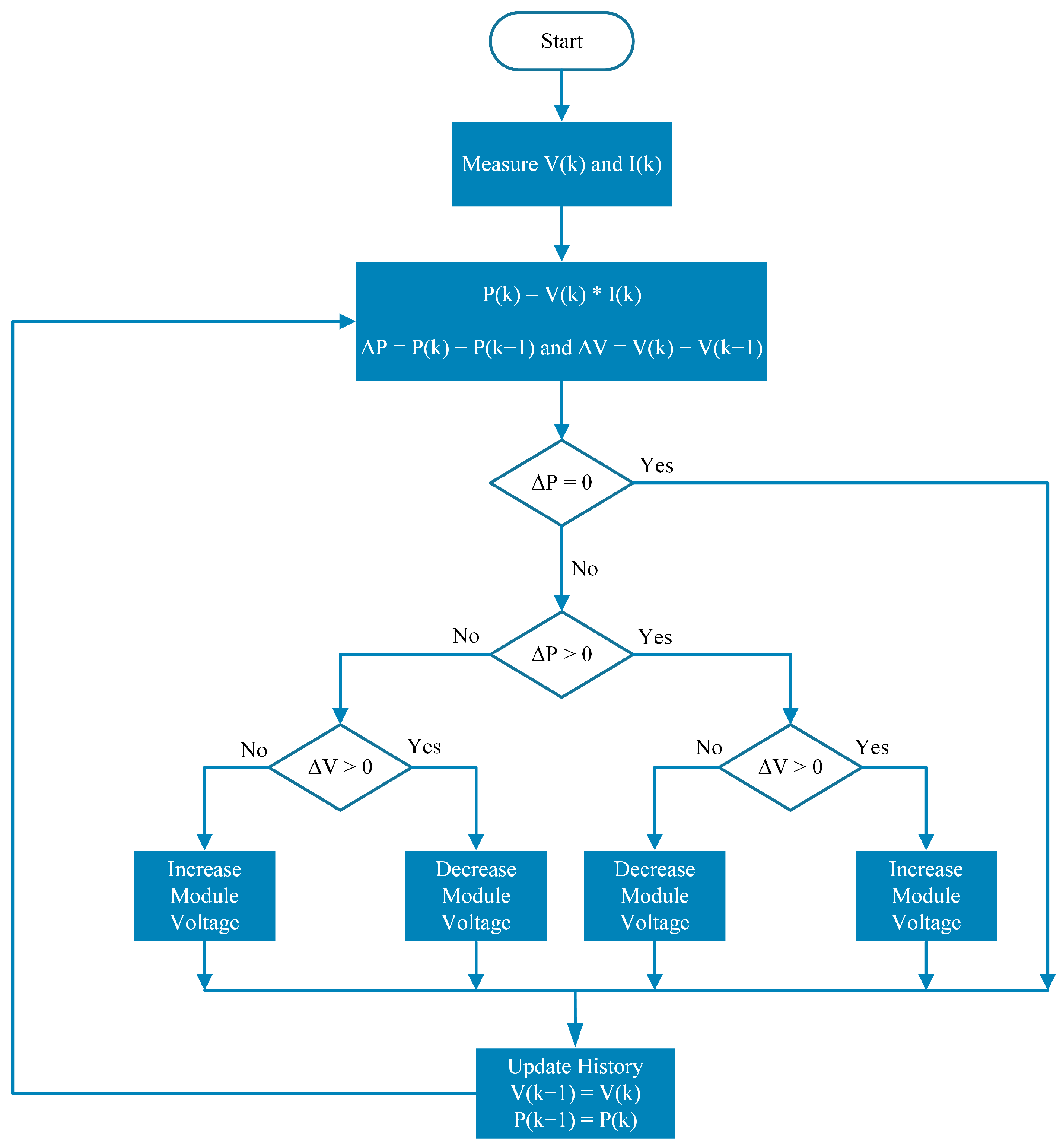
2.3.1. Design of Perturb & Observe MPPT Algorithm

The Perturb & Observe MPPT algorithm is a traditional online MPPT algorithm. It is one of the most studied and implemented MPPT methods due to its simple structure and low cost. In this algorithm, power is calculated using the voltage and current values measured from the PV array. Power and voltage values are compared with the previous power and voltage values. The duty cycle or reference voltage value is adjusted according to the change in output power. The increment or decrement of the reference voltage affects the power output of the PV module. In this manner, the perturbation direction of the duty cycle or reference voltage can be determined in line with the change in power. The flowchart of Perturb & Observe MPPT algorithm is given in Figure 4.

2.3.2. Design of Kalman Filter and Perturb & Observe Hybrid MPPT Algorithm

This algorithm is created by combining the Kalman Filter and the Perturb & Observe MPPT algorithm. An efficient hybrid method is created by combining the strengths of both algorithms. The Kalman Filter (KF) is used to make an accurate estimate in cases of uncertainty or noise. The Kalman Filter observes the previous system state and estimates the next states. It consists of two stages; the first stage is the estimation stage. The second stage is the update stage. The Kalman Filter can be expressed mathematically by the following equations [59].
The estimated state is calculated in Equation (9).
x k = A x k 1 + B u k 1
The estimated error covariance is as in Equation (10).
H k = A H k 1 A T + Q
The gain matrix calculation is shown in Equation (11).
K k = H k C T C H k C T + R 1
The updated state estimate is represented in Equation (12).
x k = x k + K k z k C x k
Finally, the updated error covariance calculation is shown in Equation (13).
H k = I H k C H k
The expected condition in the anticipated iteration k from the preceding iteration is denoted by x k . The k 1 iteration process’s control step is u k 1 . The corrected status in the iteration k 1 is x k 1 . A serves as the preceding state’s transition phase. The covariance procedure is denoted by Q. One of the constants utilized in the control process is B. The error in covariance is H k 1 . We call the covariance prior H k . The rectified state is denoted by x k . Output z k is used for updating the estimation x k . K k represents the Kalman gain. H k represents the error’s covariance. z k represents the value being measured. The noise covariance is denoted by R. C is a system-related constant [59]. The flowchart of the Kalman Filter and Perturb & Observe MPPT algorithm is shown in Figure 5.
In this hybrid algorithm, the voltage and current measurements of the PV array are first performed. The power value is calculated using these measurements. When the conventional P&O algorithm is considered, the main advantage of this hybrid algorithm lies behind the determination of the change in power. The instantaneous power value is calculated by using the electrical parameters of the PV module and denoted as P k 1 in the algorithm. Then, a future power state is estimated by the Kalman Filter based on past estimations and stated as P k .

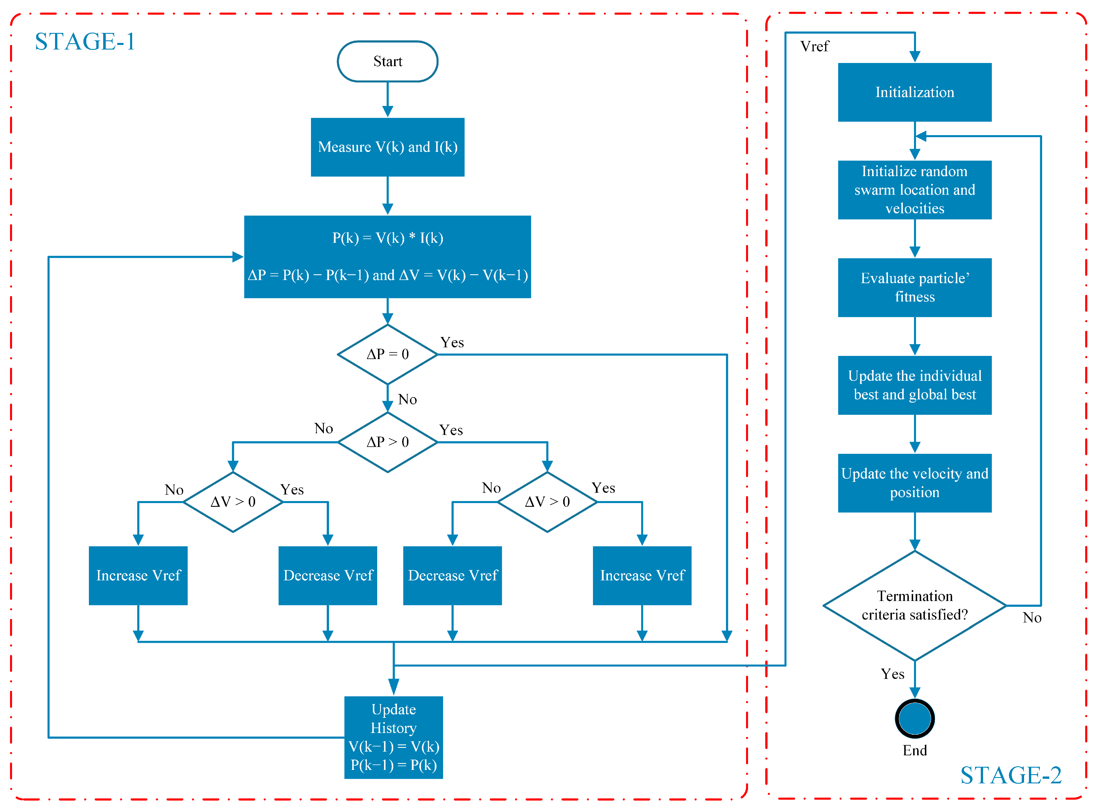
2.3.3. The Proposed Algorithm: Design of the Perturb & Observe and Particle Swarm Optimization MPPT Algorithm

This algorithm is formed by combining Perturb & Observe and Particle Swarm Optimization MPPT algorithms. A good hybrid method is developed by using the advantageous aspects of both algorithms. The Particle Swarm Optimization (PSO) algorithm is a method created by taking the swarm behavior of living beings in nature as an example. In this algorithm, a cluster of particles is created. Particles move in the solution space. These particles, which are constantly moving, search for the best solution. In this algorithm, the initial positions are determined randomly. Each particle has speed and position information. Position information also represents a solution. Moving particles make their next moves according to their distance and position to the appropriate value. Speed and positions are constantly updated in the algorithm. The algorithm has various parameters, and the algorithm can gain different advantages according to the values of these parameters. As a result, the algorithm continues to iterate until it finds the best result.
The PSO algorithm can be expressed mathematically by Equations (14) and (15) [60].
v i t + 1 = w × v i t + c 1 × r 1 × p b e s t x i t + c 2 × r 2 × g b e s t x i t
x i t + 1 = x i t + v i t + 1
The velocity of the particle is calculated in Equation (14). In Equation (15), the position of the particle is determined. Here, the letter i is the particle number. t indicates the current state. The expressions indicated by t + 1 indicate the next state. v i , represents the velocity vector of the particle. w is the coefficient of inertia and determines how much the particle maintains its previous speed. The cognitive and social components are expressed as coefficients c 1 and c 2 . The coefficients r 1 and r 2 consist of random numbers (between 0 and 1) and make the particle motion random. The current position of the particle can be expressed as x i . The best position of the particle is shown by p b e s t . The best position of the entire swarm is expressed as g b e s t [60].
In this algorithm, a MATLAB code containing the Perturb & Observe algorithm and the PSO algorithm is prepared in the MATLAB function block. First, voltage and current information are obtained from the PV array. The power value is calculated using these measurements. The Perturb & Observe method starts the algorithm at the first stage. The Perturb & Observe algorithm compares the previous states of the power and voltage information and produces the reference voltage. The generated reference voltage enters the PSO algorithm. Here, the best solution is tried again. Finally, the PSO algorithm produces a suitable reference voltage. These algorithms will work continuously one after the other in order to follow the MPP.
In this algorithm, a PI controller is used. The PWM signal is generated in the control circuit and the DC-DC boost converter is switched. The peak value of the carrier signal is selected as 0.6 and its frequency is 20 kHz. Figure 6 shows the flowchart of the applied P&O and PSO Hybrid MPPT method.

3. Results and Discussion

In this section, simulations with the MPPT algorithms and the proposed hybrid MPPT method are tested under specified conditions and the results are reviewed and compared with each other. The values of the design components are the same in all simulations, and only the MATLAB/Simulink function varies in terms of MPPT algorithms. A signal generator is used as the irradiance source in the PV systems. Simulations with the algorithms are tested under the same conditions with 1000 W/m2, 800 W/m2, 600 W/m2, 500 W/m2 and 900 W/m2 irradiance values. The responses of the algorithms in this study are observed under constant and variable irradiance conditions. Then, MPPT algorithms are compared with the proposed method, and the results are interpreted. Figure 7 shows the variation of the irradiance.
In addition, each of the methods is tested separately with simulations using the real solar irradiance data below. The irradiance graph containing the real solar irradiance data is shown in Figure 8.

3.1. Operating Scenario of the Overall System: Perturb & Observe MPPT Algorithm

In this section, PV system simulation with the Perturb & Observe Algorithm is performed. The algorithm tracks the MPP and generates the reference voltage value. The generated signal is applied in the PI controller and comparator to produce the PWM signal. A successful MPP tracking is performed by using the right duty cycle. In the simulation results, the voltage, current and power of the PV array are reviewed. In addition, the PV array voltage has been compared with the reference voltage produced in the Perturb & Observe algorithm. It has been seen that the reference voltage has followed the PV array voltage. The advantageous aspects of this method are determined. The PV array output voltage graph and converter output voltage graph of the system using the Perturb & Observe MPPT algorithm under varying irradiance conditions are seen in Figure 9.
In addition, the PV array output power and converter output power graph containing the real solar irradiance data are shown in Figure 10.
PV array output voltage and reference voltage graphs for the Perturb & Observe MPPT method under varying irradiance conditions are shown in Figure 11. The green color represents the PV array voltage and the purple color represents the reference voltage generated in the Perturb & Observe algorithm. It is also shown in close perspective with varying irradiance phase. In this scenario, the MPP is successfully followed by the MPPT algorithm. Moreover, compared to the case where the MPPT controller is not used, more stable signals are formed during irradiance changes.
In addition, a PV array output voltage and reference voltage graph containing the real solar irradiance data is shown in Figure 12.

3.2. Operating Scenario of the Overall System: Kalman Filter and the Perturb & Observe Hybrid MPPT Algorithm

In this case, a hybrid Perturb & Observe and Kalman Filter algorithm is tested. PWM signal is generated using the reference voltage. The boost converter is operated and the MPP point is tracked successfully. Voltage, current, power and reference signal comparisons are performed for the PV array and DC-DC boost converter. Since the Kalman Filter is only a mathematical process, it is useful to combine it with the Perturb & Observe method in a hybrid structure as a low-cost solution.
The graph shown in Figure 13 is the PV array output power graph and converter output power graph for the KF and P&O Hybrid MPPT method under varying irradiance conditions.
In addition, PV array output power and converter output power for KF and P&O Hybrid MPPT method graph containing the real solar irradiance data is shown in Figure 14.
Figure 15 shows the PV array output voltage and reference voltage graphs. The graph also shows that MPP is tracked successfully. The green color represents the PV array voltage, and the blue color represents the reference voltage generated in the MPPT algorithm.
In addition, the PV array output voltage and reference voltage graph containing the real solar irradiance data are shown in Figure 16.

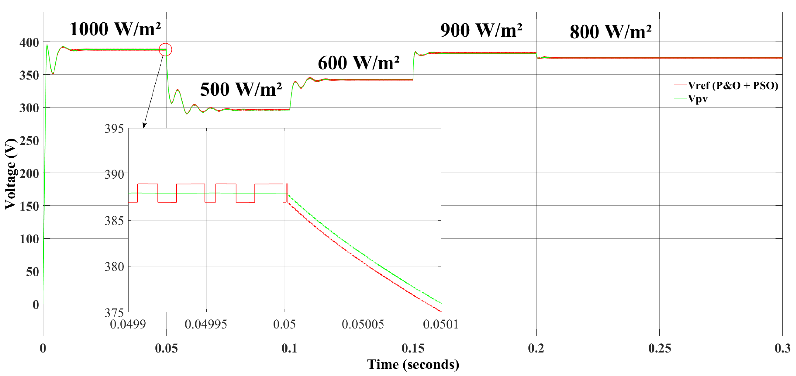
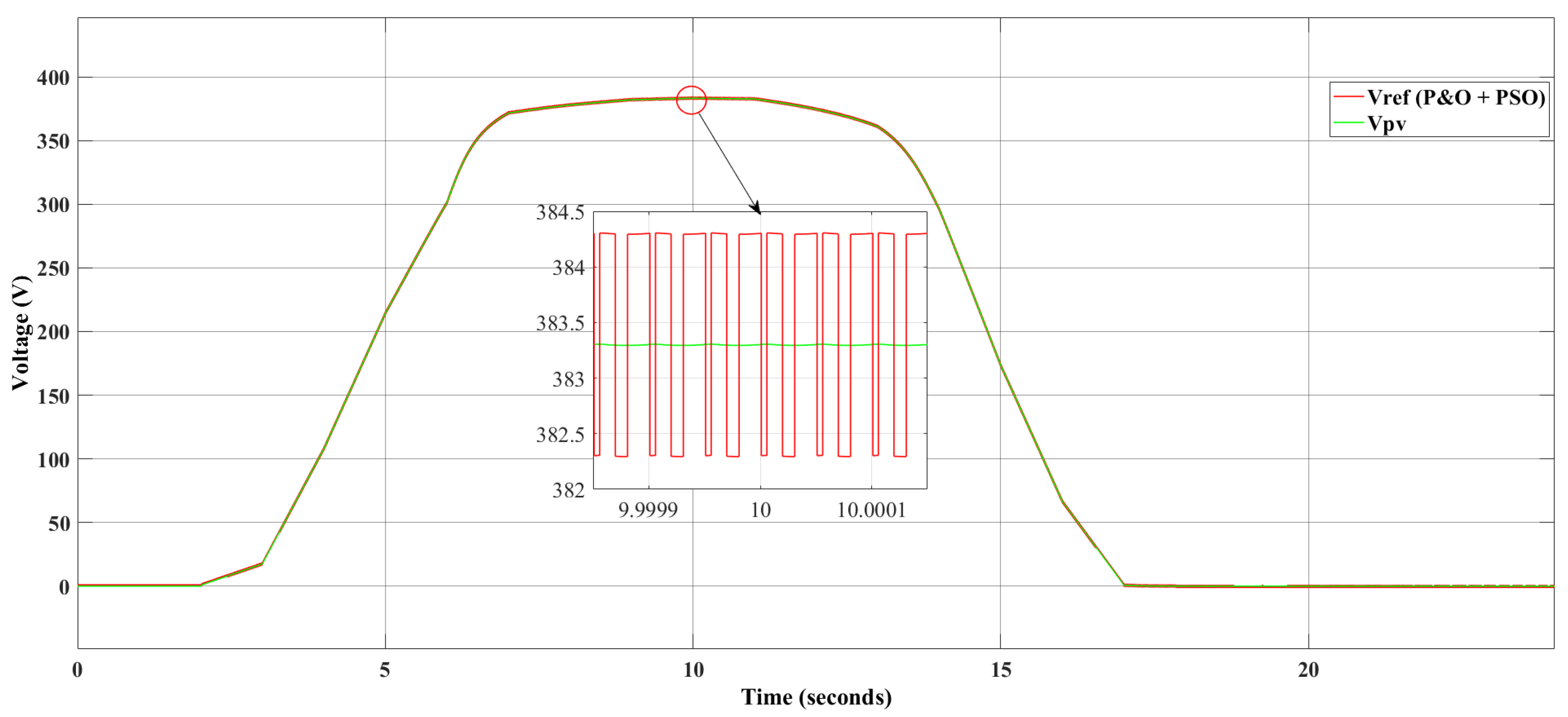
3.3. Operating Scenario of the Overall System: Perturb & Observe and Particle Swarm Optimization Hybrid MPPT Algorithm

In this section, the Perturb & Observe and Particle Swarm Optimization Hybrid MPPT Algorithm is tested in the simulation environment using the previously introduced PV system. The algorithm uses the reference voltage and follows MPP. The PWM signal is generated and the boost converter is run. The PV array voltage, current and power graphs resulting from the simulation are examined. In addition, the boost converter’s voltage, current and power graphs are also examined. The PSO algorithm is considered a good method because it performs a detailed MPP search.
The graphs in Figure 17 are the PV array output power graph and converter output power graph.
In addition, the PV array output power and converter output power graph containing the real solar irradiance data is shown in Figure 18.
The graph given in Figure 19 is the PV array output voltage and reference voltage graphs. MPP is successfully followed. The green color represents the PV array voltage and red color represents the reference voltage generated in the MPPT algorithm.
In addition, PV array output voltage and reference voltage graph containing the real solar irradiance data is shown in Figure 20.

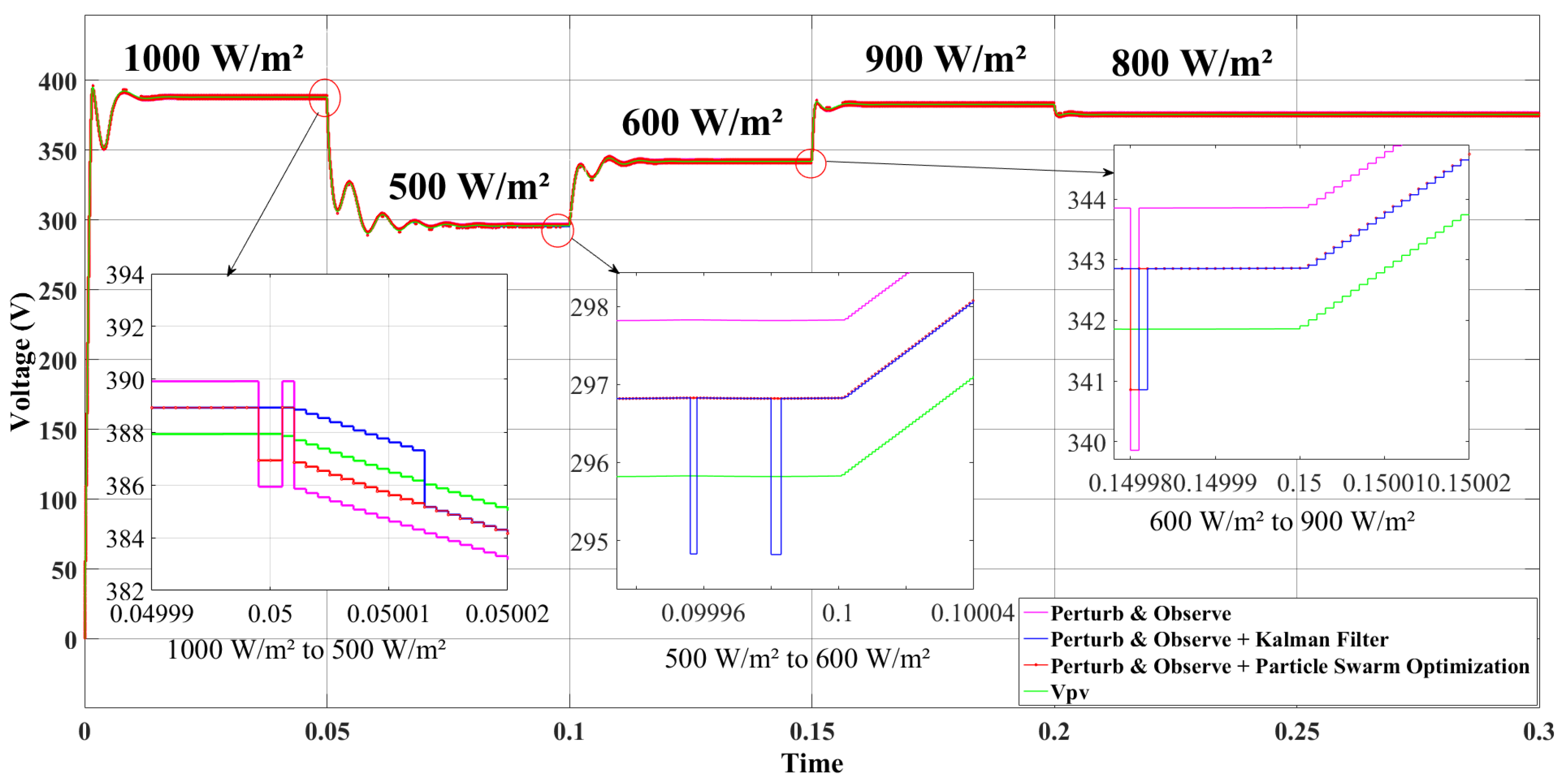
3.4. Comparison of the Proposed Method with the Other Methods

In this section, the simulation cases are analyzed in detail. For all simulations made, except for the algorithm codes in the MATLAB/Simulink Function block, all remaining circuit elements and values are the same. A signal generator is used for all simulation cases and 1000 W/m2, 800 W/m2, 600 W/m2, 500 W/m2 and 900 W/m2 irradiance values are given, respectively. Then, all simulation cases and the PV system including the proposed MPPT method are tested. The method proposed in this study is Perturb & Observe and Particle Swarm Optimization Hybrid Algorithm. The reference voltage generation graph is examined in detail compared to other simulation graphs.
In the proposed algorithm, the reference voltage tracking speed is better than that of the other algorithms. It is seen that the reference voltage fluctuation is lower than that of other methods. It is observed that a graph closer to the reference voltage in terms of voltage value is formed. In most close-up views, the voltage pulses seen in other algorithms are lower or not seen at all. Simulation results show that the proposed Perturb & Observe and Particle Swarm Optimization Hybrid MPPT algorithm is a more efficient algorithm than the other algorithms.
The following graphs show the reference voltage plots for all running simulation cases. Purple represents the Perturb & Observe MPPT method. Blue represents the Perturb & Observe and Kalman Filter Hybrid MPPT method. Red represents the proposed Perturb & Observe and Particle Swarm Optimization Hybrid MPPT algorithm. Lastly, green represents the PV array voltage.
Figure 21 and Figure 22 show the reference voltages produced by different algorithms in a case where the irradiance value changes seriatim. When the graph is examined, the proposed P&O and PSO Hybrid MPPT algorithm produce a closer reference voltage than the P&O MPPT algorithm. Compared to the P&O and KF Hybrid MPPT algorithm, the pulse signal appearance is less or absent in the reference voltage graph of the proposed method.
As seen in these graphs, the P&O and PSO Hybrid MPPT algorithm provides tracking earlier than the P&O and KF Hybrid MPPT algorithm. When the reference voltages produced by different algorithms are in a stable situation where the irradiance value is constant, the P&O and PSO Hybrid MPPT algorithm produces a more stable and accurate reference signal than the other algorithms.
The energy production at the MPP provided by the proposed MPPT method according to real solar irradiance data is given in Table 4.
In summary, the simulation results are compared and evaluated in terms of accuracy and tracking speed. Table 5 includes these comparisons. In the PV system where the Perturb & Observe MPPT algorithm is used, the reference voltage is followed by MMP at a moderate level compared to the other methods.
In the simulation of the PV system where the Perturb & Observe and Kalman Filter Hybrid MPPT algorithm is used, the reference signal tracking is at a medium level. It has been observed that its performance at times of irradiance change is also at a medium level compared to the others.
In the PV system simulation where the Perturb & Observe and Particle Swarm Optimization Hybrid MPPT algorithm is used, a higher accuracy MPP tracking is observed compared to the others. It is understood that fast tracking is carried out at the moments of irradiance value change.
If the limitations of the method proposed in this study are mentioned in terms of benefiting future studies and literature, there may be a possibility of steady-state oscillation for the P&O method under various conditions in the system. In addition, powerful hardware may be needed due to the computational load of the PSO algorithm. Finally, it is useful to take into account that if the parameters of the PSO algorithm are not chosen well, the algorithm may get stuck in local minima.

4. Conclusions

In this study, a new hybrid MPPT method that combines the Perturb & Observe and Particle Swarm Optimization algorithms has been successfully developed and tested in MATLAB/Simulink. The proposed MPPT method leverages the strengths of both P&O and PSO techniques to achieve faster convergence, lower voltage undershoots, and higher tracking accuracy. The proposed method is validated through simulations and compared with the conventional P&O and P&O-Kalman Filter Hybrid MPPT methods under varying irradiance conditions. The obtained results demonstrate that the proposed hybrid approach significantly improves the tracking performance and reference voltage accuracy, especially under partial shading conditions. The proposed hybrid MPPT algorithm has been tested by running it with two other simulation scenarios, namely the PV system with the Perturb & Observe algorithm and the PV system using the Perturb & Observe and Kalman Filter Hybrid MPPT algorithm. The proposed method and other two simulation studies have been tested in the MATLAB/Simulink simulation program using 1000 W/m2, 500 W/m2, 600 W/m2, 900 W/m2 and 800 W/m2 irradiance values, respectively. In the Perturb & Observe MPPT algorithm, the undershoot voltage is determined as 3 V. In the Perturb & Observe and Kalman Filter Hybrid MPPT method, the undershoot voltage is seen to be 2 V. In the proposed Perturb & Observe and Particle Swarm Optimization Hybrid MPPT method, a lower undershoot voltage compared to the others is determined as 1.5 V. When the simulated methods are examined, it is seen that the convergence times for the Perturb & Observe MPPT algorithm, Perturb & Observe and Kalman Filter Hybrid MPPT method, and the proposed Perturb & Observe and Particle Swarm Optimization Hybrid MPPT method are 8 ms, 6 ms, and 5 ms, respectively. These improvements make it highly suitable for practical PV systems operating under partial shading conditions. In addition to these simulation studies, the proposed hybrid method has been tested with real solar irradiance and temperature data. In simulations with real solar irradiance data, the proposed method performs more electric power production. This paper contributes to the literature by expressing some limitations of the proposed method. Under changing irradiance conditions, steady state oscillation can be observed in the Perturb & Observe method. In addition, the Particle Swarm Optimization algorithm may create excessive processing load on hardware and may require more powerful hardware setups. Finally, parameter selection is the most important part for PSO algorithm, and if the selection is not performed well, local MPP points may be detected incorrectly. Future work will focus on hardware implementation to further validate the proposed method. The use of more advanced power converters and grid integration is planned. In addition, the proposed method will be tested by using it in newly installed PV plants. The method performance will be improved by better tuning the control and algorithm parameters to improve the performance.

Author Contributions

Conceptualization, O.T. and B.K.U.; methodology, O.T. and B.K.U.; software, O.T. and B.K.U.; validation, O.T. and B.K.U.; formal analysis, O.T. and B.K.U.; investigation, O.T. and B.K.U.; resources, O.T and B.K.U.; data curation, O.T. and B.K.U.; writing—original draft preparation, O.T. and B.K.U.; writing—review and editing, O.T. and B.K.U.; visualization, O.T. and B.K.U.; supervision, O.T.; project administration, O.T. All authors have read and agreed to the published version of the manuscript.

Funding

This research received no external funding.

Institutional Review Board Statement

Not applicable.

Informed Consent Statement

Not applicable.

Data Availability Statement

The data presented in this study are available on request from the corresponding author.

Conflicts of Interest

The authors declare no conflicts of interest.

Abbreviations

The following abbreviations are used in this manuscript:
ANNArtificial Neural Networks
CPSCrow Pattern Search
CSCuckoo Search
DEDifferential Evolution
FLCFuzzy Logic Controller
FOCVFractional Open Circuit Voltage
DEDifferential Evolution
FSCCFractional Short Circuit Current
GAGenetic Algorithm
GWOGrey Wolf Optimization
HCHill Climbing
ICIncremental Conductance
IGBTInsulated-Gate Bipolar Transistor
KFKalman Filter
LuTLook up Table
MPCModel Predictive Control
MPPMaximum Power Point
MPPTMaximum Power Point Tracking
P&OPerturb & Observe
PIProportional-Integral
PSOParticle Swarm Optimization
PVPhotovoltaic
PWMPulse Width Modulation
SFLAShuffled Frog Leaping Algorithm
SSASalp Swarm Algorithm
STCStandard Test Conditions
WOWhale Optimization

References

  1. El-Helw, H.M.; Magdy, A.; Marei, M.I. A hybrid maximum power point tracking technique for partially shaded photovoltaic arrays. IEEE Access 2017, 5, 11900–11908. [Google Scholar] [CrossRef]
  2. Joisher, M.; Singh, D.; Taheri, S.; Espinoza-Trejo, D.R.; Pouresmaeil, E.; Taheri, H. A hybrid evolutionary-based MPPT for photovoltaic systems under partial shading conditions. IEEE Access 2020, 8, 38481–38492. [Google Scholar] [CrossRef]
  3. Al-Ezzi, A.S.; Ansari, M.N.M. Photovoltaic solar cells: A review. Appl. Syst. Innov. 2022, 5, 67. [Google Scholar] [CrossRef]
  4. Dambhare, M.V.; Butey, B.; Moharil, S.V. Solar photovoltaic technology: A review of different types of solar cells and its future trends. In Proceedings of the International Conference on Research Frontiers in Sciences (ICRFS 2021), Nagpur, India, 5–6 February 2021. [Google Scholar]
  5. Gao, C.; Chen, H. Electricity from renewable energy resources: Sustainable energy transition and emissions for developed economies. Util. Policy 2023, 82, 101543–101554. [Google Scholar] [CrossRef]
  6. International Energy Agency. Global Energy Review 2025; Technical Report; International Energy Agency: Paris, France, 2025; Available online: https://www.iea.org/reports/global-energy-review-2025 (accessed on 25 June 2025).
  7. Motahhir, S.; Chtita, S.; Chouder, A.; Hammoumi, A.E. Enhanced energy output from a PV system under partial shaded conditions through grey wolf optimizer. Clean. Eng. Technol. 2022, 9, 100533–100543. [Google Scholar] [CrossRef]
  8. Singh, V.; Tiwari, A. Study and comparison of various types of converters used for solar PV: A review. In Proceedings of the 2018 International Conference on Power Energy, Environment and Intelligent Control (PEEIC), Greater Noida, India, 13–14 April 2018. [Google Scholar]
  9. Bingöl, O.; Özkaya, B. Analysis and comparison of different PV array configurations under partial shading conditions. Sol. Energy 2018, 160, 336–343. [Google Scholar] [CrossRef]
  10. Eke, R.; Demircan, C. Shading effect on the energy rating of two identical PV systems on a building façade. Sol. Energy 2015, 122, 48–57. [Google Scholar] [CrossRef]
  11. Schuss, C.; Kotikumpu, T.; Eichberger, B.; Rahkonen, T. Impact of dynamic environmental conditions on the output behaviour of photovoltaics. In Proceedings of the 20th IMEKO TC4 International Symposium and 18th International Workshop on ADC Modelling and Testing Research on Electric and Electronic Measurement for the Economic Upturn, Benevento, Italy, 15–17 September 2014. [Google Scholar]
  12. Kumari, P.A.; Geethanjali, P. Parameter estimation for photovoltaic system under normal and partial shading conditions: A survey. Renew. Sustain. Energy Rev. 2018, 84, 1–11. [Google Scholar] [CrossRef]
  13. Hahn, D.; Daßler, D.; Schindler, S.; Götz, D.; Gottschalg, R.; Dassler, D.; Hanifi, H. Evaluation of shading tolerance of PV modules with different module designs for mobile application by simulation, indoor and outdoor. In Proceedings of the 36th European Photovoltaic Solar Energy Conference and Exhibition, Marseille, France, 9–13 September 2019. [Google Scholar]
  14. Brecl, K.; Bokalič, M.; Topič, M. Annual energy losses due to partial shading in PV modules with cut wafer-based Si solar cells. Renew. Energy 2021, 168, 195–203. [Google Scholar] [CrossRef]
  15. Bi, Z.; Ma, J.; Man, K.; Smith, J.; Yue, Y.; Wen, H. Global MPPT method for photovoltaic systems operating under partial shading conditions using the 0.8 VOC model. In Proceedings of the 2019 IEEE International Conference on Environment and Electrical Engineering and 2019 IEEE Industrial and Commercial Power Systems Europe, Genova, Italy, 11–14 June 2019. [Google Scholar]
  16. Trzmiel, G.; Głuchy, D.; Kurz, D. The impact of shading on the exploitation of photovoltaic installations. Renew. Energy 2020, 153, 480–498. [Google Scholar] [CrossRef]
  17. Torkian, F.; Ghandehari, R. Power recovery of the PV arrays under partial shading by a power electronic compensator. Sol. Energy 2022, 237, 284–292. [Google Scholar] [CrossRef]
  18. Mohapatra, A.; Nayak, B.; Das, P.; Mohanty, K.B. A review on MPPT techniques of PV system under partial shading condition. Renew. Sustain. Energy Rev. 2017, 80, 854–867. [Google Scholar] [CrossRef]
  19. Yang, B.; Zhu, T.; Wang, J.; Shu, H.; Yu, T.; Zhang, X.; Yao, W.; Sun, L. Comprehensive overview of maximum power point tracking algorithms of PV systems under partial shading condition. J. Clean. Prod. 2020, 268, 121983–122007. [Google Scholar] [CrossRef]
  20. Zhu, W.; Shang, L.; Li, P.; Guo, H. Modified hill climbing MPPT algorithm with reduced steady-state oscillation and improved tracking efficiency. J. Eng. 2018, 2018, 1878–1883. [Google Scholar] [CrossRef]
  21. Lasheen, M.; Abdel-Salam, M. Maximum power point tracking using hill climbing and ANFIS techniques for PV applications: A review and a novel hybrid approach. Energy Convers. Manag. 2018, 171, 1002–1019. [Google Scholar] [CrossRef]
  22. Motsoeneng, P.; Bamukunde, J.; Chowdhury, S. Comparison of perturb & observe and hill climbing MPPT schemes for PV plant under cloud cover and varying load. In Proceedings of the 10th International Renewable Energy Congress (IREC 2019), Sousse, Tunisia, 26–28 March 2019. [Google Scholar]
  23. Kwan, T.H.; Wu, X. The lock-on mechanism MPPT algorithm as applied to the hybrid photovoltaic cell and thermoelectric generator system. Appl. Energy 2017, 204, 873–886. [Google Scholar] [CrossRef]
  24. Sulthan, S.M.; Devaraj, D.; Sri Revathi, B.; Mohammed Mansoor, O.; Raj, V. Development and analysis of a two stage Hybrid MPPT algorithm for solar PV systems. Energy Rep. 2023, 9, 1502–1512. [Google Scholar] [CrossRef]
  25. Yüksek, G.; Mete, A.N. A hybrid variable step size MPPT method based on P&O and INC methods. In Proceedings of the 2017 10th International Conference on Electrical and Electronics Engineering (ELECO), Bursa, Turkey, 30 November–2 December 2017. [Google Scholar]
  26. Irmak, E.; Güler, N. A model predictive control-based hybrid MPPT method for boost converters. Int. J. Electron. 2020, 107, 1–16. [Google Scholar] [CrossRef]
  27. Lemmassi, A.; Derouich, A.; Hanafi, A.; Byou, A.; Benmessaoud, M.; El Quanjli, N. Low-cost MPPT for triple-junction solar cells used in nanosatellites: A comparative study between P&O and INC algorithms. e-Prime—Adv. Electr. Eng. Electron. Energy 2024, 7, 100426. [Google Scholar] [CrossRef]
  28. Sher, H.A.; Murtaza, A.F.; Noman, A.; Addoweesh, K.E.; Al-Haddad, K.; Chiaberge, M. A new sensorless hybrid MPPT algorithm based on fractional short-circuit current measurement and P&O MPPT. IEEE Trans. Sustain. Energy 2015, 6, 1426–1434. [Google Scholar] [CrossRef]
  29. Shetty, D.; Sabhahit, J.N. Grey wolf optimization and incremental conductance based hybrid MPPT technique for solar powered induction motor driven water pump. Int. J. Renew. Energy Dev. 2024, 13, 52–61. [Google Scholar] [CrossRef]
  30. Chiu, C.S.; Ngo, S. Hybrid SFLA MPPT design for multi-module partial shading photovoltaic energy systems. Int. J. Electron. 2023, 110, 199–220. [Google Scholar] [CrossRef]
  31. Kacimi, N.; Grouni, S.; Idir, A.; Boucherit, M.S. New improved hybrid MPPT based on neural network-model predictive control-Kalman Filter for photovoltaic system. Indones. J. Electr. Eng. Comput. Sci. 2020, 20, 1230–1241. [Google Scholar] [CrossRef]
  32. Basiński, K.; Ufnalski, B.; Grzesiak, L.M. Hybrid MPPT algorithm for PV systems under partially shaded conditions using a stochastic evolutionary search and a deterministic hill climbing. Power Electron. Drives 2017, 2, 49–59. [Google Scholar] [CrossRef]
  33. Assam, B.; Messalti, S.; Harrag, A. New improved hybrid MPPT based on backstepping-sliding mode for PV system. J. Eur. Des Syst. Autom. 2019, 52, 317–323. [Google Scholar] [CrossRef]
  34. Rizzo, S.A.; Scelba, G. A hybrid global MPPT searching method for fast variable shading conditions. J. Clean. Prod. 2021, 298, 126775. [Google Scholar] [CrossRef]
  35. Ghosh, S. IBS - P&O hybrid MPPT algorithm for solar PV applications. In Proceedings of the 2019 IEEE PES GTD Grand International Conference and Exposition Asia (GTD Asia), Bangkok, Thailand, 19–23 March 2019. [Google Scholar]
  36. Tao, H.; Ghahremani, M.; Ahmed, F.W.; Jing, W.; Nazir, M.S.; Ohshima, K. A novel MPPT controller in PV systems with hybrid whale optimization-PS algorithm based ANFIS under different conditions. Control Eng. Pract. 2021, 112, 104809. [Google Scholar] [CrossRef]
  37. Hassan, A.; Bass, O.; Masoum, M.A. An improved genetic algorithm based fractional open circuit voltage MPPT for solar PV systems. Energy Rep. 2023, 9, 1535–1548. [Google Scholar] [CrossRef]
  38. Ncir, N.; Akchioui, N.E.; Fathi, A.E. Enhancing photovoltaic system modeling and control under partial and complex shading conditions using a robust hybrid DE-FFNN MPPT strategy. Renew. Energy Focus 2023, 47, 100504. [Google Scholar] [CrossRef]
  39. Ahmed, E.M.; Norouzi, H.; Alkhalaf, S.; Ali, Z.M.; Dadfar, S.; Furukawa, N. Enhancement of MPPT controller in PV-BES system using incremental conductance along with hybrid crow-pattern search approach based ANFIS under different environmental conditions. Sustain. Energy Technol. Assess. 2022, 50, 101812. [Google Scholar] [CrossRef]
  40. Hilali, A.; El Marghichi, M.; Makhad, M.; Loulijat, A.; El Quanjli, N.; Mossa, M.A.; Almalki, M.M.; Alghamdi, T.A.H. Optimization of solar water pumping systems through a combined approach based on MPPT-Bat and DTC. PLoS ONE 2024, 19, e0309330. [Google Scholar] [CrossRef] [PubMed]
  41. Mohanty, S.; Subudhi, B.; Ray, P.K. A grey wolf-assisted perturb & observe MPPT algorithm for a PV system. IEEE Trans. Energy Convers. 2017, 32, 340–347. [Google Scholar] [CrossRef]
  42. Chao, K.H.; Rizal, M.N. A hybrid MPPT controller based on the genetic algorithm and ant colony optimization for photovoltaic systems under partially shaded conditions. Energies 2021, 14, 2902. [Google Scholar] [CrossRef]
  43. Salim, J.A.; Albaker, B.M.; Alwan, M.S.; Hasanuzzaman, M. Hybrid MPPT approach using cuckoo search and grey wolf optimizer for PV systems under variant operating conditions. Glob. Energy Interconnect. 2022, 5, 627–644. [Google Scholar] [CrossRef]
  44. Elymany, M.M.; Enany, M.A.; Elsonbaty, N.A. Hybrid optimized-ANFIS based MPPT for hybrid microgrid using zebra optimization algorithm and artificial gorilla troops optimizer. Energy Convers. Manag. 2024, 299, 117809. [Google Scholar] [CrossRef]
  45. Nabipour, M.; Razaz, M.; Seifossadat, S.G.; Mortazavi, S.S. A new MPPT scheme based on a novel fuzzy approach. Renew. Sustain. Energy Rev. 2017, 74, 1147–1169. [Google Scholar] [CrossRef]
  46. Rizzo, S.A.; Salerno, N.; Scelba, G.; Sciacca, A. Enhanced hybrid global MPPT algorithm for PV systems operating under fast-changing partial shading conditions. Int. J. Renew. Energy Res. 2018, 8, 221–229. [Google Scholar] [CrossRef]
  47. Padmanaban, S.; Priyadarshi, N.; Bhaskar, M.S.; Holm-Nielsen, J.B.; Ramachandaramurthy, V.K.; Hossain, E. A hybrid ANFIS-ABC based MPPT controller for PV system with anti-islanding grid protection: Experimental realization. IEEE Access 2019, 7, 103377–103389. [Google Scholar] [CrossRef]
  48. Çelik, Ö.; Teke, A. A hybrid MPPT method for grid connected photovoltaic systems under rapidly changing atmospheric conditions. Electr. Power Syst. Res. 2017, 152, 194–210. [Google Scholar] [CrossRef]
  49. Li, Y.; Samad, S.; Ahmed, F.W.; Abdulkareem, S.S.; Hao, S.; Rezvani, A. Analysis and enhancement of PV efficiency with hybrid MSFLA–FLC MPPT method under different environmental conditions. J. Clean. Prod. 2020, 271, 122195. [Google Scholar] [CrossRef]
  50. Priyadarshi, N.; Padmanaban, S.; Holm-Nielsen, J.B.; Blaabjerg, F.; Bhaskar, M.S. An experimental estimation of hybrid ANFIS-PSO-based MPPT for PV grid integration under fluctuating sun irradiance. IEEE Syst. J. 2020, 14, 1218–1229. [Google Scholar] [CrossRef]
  51. Mezdi, K.E.; Magri, A.E.; Watil, A.; Myasse, I.E.; Bahatti, L.; Lajouad, R.; Ouabi, H. Nonlinear control design and stability analysis of hybrid grid-connected photovoltaic-battery energy storage system with ANN-MPPT method. J. Energy Storage 2023, 72, 108747. [Google Scholar] [CrossRef]
  52. Ge, X.; Ahmed, F.W.; Rezvani, A.; Aljojo, N.; Samad, S.; Foong, L.K. Implementation of a novel hybrid BAT-fuzzy controller based MPPT for grid-connected PV-battery system. Control Eng. Pract. 2020, 98, 104380. [Google Scholar] [CrossRef]
  53. Pradhan, C.; Senapati, M.K.; Malla, S.G.; Nayak, P.K.; Gjengedal, T. Coordinated power management and control of standalone PV-hybrid system with modified IWO-based MPPT. IEEE Syst. J. 2020, 15, 3585–3596. [Google Scholar] [CrossRef]
  54. Balaji, V.; Fathima, A.P. Hybrid algorithm for MPPT tracking using a single current sensor for partially shaded PV systems. Sustain. Energy Technol. Assess. 2022, 53, 102415. [Google Scholar] [CrossRef]
  55. Eltamaly, A.M. A novel musical chairs algorithm applied for MPPT of PV systems. Renew. Sustain. Energy Rev. 2021, 146, 111135. [Google Scholar] [CrossRef]
  56. Hu, Z.; Norouzi, H.; Jiang, M.; Dadfar, S.; Kashiwagi, T. Novel hybrid modified krill herd algorithm and fuzzy controller based MPPT to optimally tune the member functions for PV system in the three-phase grid-connected mode. ISA Trans. 2022, 129, 214–229. [Google Scholar] [CrossRef]
  57. Boujelben, N.; Masmoudi, F.; Djemel, M.; Derbel, N. Design and comparison of quadratic boost and double cascade boost converters with boost converter. In Proceedings of the 2017 14th International Multi-Conference on Systems, Signals & Devices (SSD), Marrakech, Morocco, 28–31 March 2017. [Google Scholar]
  58. Adnan, M.F.; Oninda, M.A.M.; Nishat, M.M.; Islam, N. Design and simulation of a DC-DC boost converter with PID controller for enhanced performance. Int. J. Eng. Res. Technol. (IJERT) 2017, 6, 27–32. [Google Scholar] [CrossRef]
  59. Neto, D.T.S.; Salles, M.B.C.; Salazar, P.D.P.; Cardoso, J.R. A Kalman Filter based MPPT algorithm. SBSE2020 2021, 1, 1–6. [Google Scholar] [CrossRef]
  60. Abdulkadir, M.; Yatim, A.H.; Yusuf, S.T. An improved PSO-based MPPT control strategy for photovoltaic systems. Int. J. Photoenergy 2014, 2014, 818232. [Google Scholar] [CrossRef]
Figure 1. Designed PV system.
Applsci 15 07386 g001
Figure 2. DC-DC boost converter circuit.
Applsci 15 07386 g002
Figure 3. Control circuit of the DC-DC boost converter.
Applsci 15 07386 g003
Figure 4. Flowchart of Perturb & Observe MPPT algorithm.
Applsci 15 07386 g004
Figure 5. Flowchart of the Kalman Filter and Perturb & Observe MPPT algorithm.
Applsci 15 07386 g005
Figure 6. Proposed flowchart of the Perturb & Observe and Particle Swarm Optimization Hybrid MPPT.
Applsci 15 07386 g006
Figure 7. Signal graph of the signal generator that produces the irradiance.
Applsci 15 07386 g007
Figure 8. Signal graph of the signal generator that produces the real solar irradiance.
Applsci 15 07386 g008
Figure 9. PV array output power and converter output power for the P&O MPPT method.
Applsci 15 07386 g009
Figure 10. PV array output power and converter output power for the P&O MPPT method with real irradiance.
Applsci 15 07386 g010
Figure 11. PV array output voltage and reference voltage for the P&O MPPT method.
Applsci 15 07386 g011
Figure 12. PV array output voltage and reference voltage for the P&O MPPT method with real irradiance.
Applsci 15 07386 g012
Figure 13. PV array output power and converter output power for the KF and P&O Hybrid MPPT method.
Applsci 15 07386 g013
Figure 14. PV array output power and converter output power for the KF and P&O Hybrid MPPT method with real irradiance.
Applsci 15 07386 g014
Figure 15. PV array output voltage and reference voltage graph for the KF and P&O Hybrid MPPT method.
Applsci 15 07386 g015
Figure 16. PV array output voltage and reference voltage graphs for the KF and P&O Hybrid MPPT method with real irradiance.
Applsci 15 07386 g016
Figure 17. PV array output power graph and converter output power graph for the P&O and PSO Hybrid MPPT method.
Applsci 15 07386 g017
Figure 18. PV array output power graph and converter output power graph for the P&O and PSO Hybrid MPPT method with real irradiance.
Applsci 15 07386 g018
Figure 19. PV array output voltage and reference voltage graphs for the P&O and PSO Hybrid MPPT method.
Applsci 15 07386 g019
Figure 20. PV array output voltage and reference voltage graphs for the P&O and PSO Hybrid MPPT method with real irradiance.
Applsci 15 07386 g020
Figure 21. The reference voltages graph produced by different algorithms in a case where the irradiance value changes.
Applsci 15 07386 g021
Figure 22. Continuation of the reference voltages graph produced by different algorithms in a case where the irradiance value changes.
Applsci 15 07386 g022
Table 1. Merits and demerits of MPPT methods.
MPPT AlgorithmMeritsDemerits
Lock-On Mechanism MPPT [23]Low MPP tracking oscillation, high performance, steady performance, adaptive duty cycle ratio measurement.Computational complexity, need for two SEPIC converters, need to extra equipments.
P&O-LuT Hybrid MPPT [24]Fast MPP tracking, fast response to changes in weather conditions, high MPPT accuracy, high efficiency.Need for extra memory.
Variable Step Size MPPT based on P&O and IC [25]Low MPP tracking oscillation, fast MPP tracking, dynamic step size.Processing load due to continuous calculation of the number of steps.
P&O-MPC Hybrid MPPT [26]Fast response time, high performance, high efficiency, control without comparison structure.Processing load due to the number of steps, computational complexity.
P&O and IC MPPT [27]Low cost system design, easy to apply MPPT, high MPPT accuracy, high efficiency, appropriate to changes in weather conditions.Special equipment may be required for spatial conditions.
P&O-FSCC Hybrid MPPT [28]Fast MPP tracking, high efficiency, appropriate for changes in weather conditions, irradiance sensorless structure, intelligent weather forecasting.Need for fast switching equipment, temporary cancellation of PV panel and possibility of power loss.
GWO-IC Hybrid MPPT [29]Fast MPP tracking, fast response to changes in weather conditions, high efficiency.Processing load due to continuous calculation of the number of steps, need special parameter selection required.
SFLA-IC Hybrid MPPT [30]Low computational time, low computational complexity, steady performance.Processing load due to the number of steps and may require good hardware, special parameter selection required.
ANN-MPC-KF Hybrid MPPT [31]Fast response to changes in weather conditions, low overshoot, high performance, high power output, high efficiency, fast MPP tracking, high MPPT accuracy.Processing load due to the number of steps and may require good hardware, the ANN algorithm may need to be trained with sufficient data, special parameter selection required.
Stochastic Evolutionary Search-Specific HC MPPT [32]Low cost system design, low computational complexity.Special parameter selection required.
Backstepping-Sliding Mode MPPT [33]Low MPP tracking oscillation, low overshoot, high performance.Computational complexity, processing load due to the number of steps and may require good hardware.
Hybrid Two-Stage Global MPPT [34]Fast response to changes in weather conditions, low energy usage, appropriate to changes in weather conditions.The ANN algorithm may need to be trained with sufficient data.
Improvised Binary Sequence-P&O Hybrid MPPT [35]Fast response to changes in weather conditions, appropriate to changes in weather conditions, precise MPP tracking.Special limitation selection required.
WO-Pattern Search Algorithm based on ANFIS [36]High power output, high efficiency, fast MPP tracking.Computational complexity, the ANFIS algorithm may need to be trained with sufficient data, special parameter selection required.
GA based FOCV MPPT [37]Fast MPP tracking, high efficiency, low MPP tracking oscillation.Computational complexity, special parameter selection required.
DE-Feed Forward Neural Network Hybrid MPPT [38]Fast MPP tracking, high efficiency, precise MPP tracking.Computational complexity, the Feed Forward Neural Network algorithm may need to be trained with sufficient data, processing load due to the number of steps and may require good hardware.
ANFIS based CPS-IC Hybrid MPPT [39]High output power, low sampling rate, low power ripple.Computational complexity, the ANFIS algorithm may need to be trained with sufficient data, special parameter selection required.
Bat Metaheuristic Optimizer MPPT [40]Low MPP tracking error, low MPP tracking oscillation, fast MPP tracking, fast response to changes in weather conditions, high efficiency.Computational complexity, need to extra sensors, special parameter selection required.
GWO-P&O Hybrid MPPT [41]Fast MPP tracking, precise MPP tracking, high MPPT accuracy.Processing load due to number of steps, special parameter selection required.
Genetic Algorithm-Ant Bee Colony Hybrid MPPT [42]High MPPT accuracy, low computational time, few calculation steps.Processing load due to the number of steps and may require good hardware, special parameter selection required.
CS-GWO Hybrid MPPT [43]Fast MPP tracking, zero oscillation in constant state, more effectiveness than GWO, highly dependable.Computational complexity, special parameter selection required.
Zebra Optimization Algorithm and Artificial Gorilla Troops Optimization based ANFIS MPPT [44]High performance, low computational time, effective hybrid design.Computational complexity, the ANFIS algorithm may need to be trained with sufficient data, special parameter selection required.
Adaptive Fuzzy Logic Controller MPPT [45]High MPPT accuracy, high performance, low power ripple.Special parameter selection required, risk of control complexity.
ANN-HC Hybrid MPPT [46]Low computational comlexity, few equipment needed, appropriate to changes in weather conditions.The ANN algorithm may need to be trained with sufficient data.
ANFIS-Ant Bee Colony Hybrid MPPT [47]Low total harmonic distortion, safe grid connection, fast response to changes in weather conditions, high efficiency, precise MPP tracking.Processing load due to the number of steps and may require good hardware, the ANFIS algorithm may need to be trained with sufficient data, special parameter selection required.
P&O-ANN Hybrid MPPT [48]High power factor, low total harmonic distortion, precise MPP tracking, low oscillation in a steady state, fast MPP tracking, high efficiency, appropriate to changes in weather conditions.The ANN algorithm may need to be trained with sufficient data, special parameter selection required.
MSFLA-FLC Hybrid MPPT [49]Precise MPP tracking, high efficiency, fast MPP tracking, high power output, integration of battery energy storage.Computational complexity, special parameter selection required.
ANFIS-PSO Hybrid MPPT [50]Precise MPP tracking, fast MPP tracking, low total harmonic distortion, low computational comlexity, no need for extra sensors, zeta converter integration.Processing load due to the number of steps and may require good hardware, the ANFIS algorithm may need to be trained with sufficient data, special parameter selection required.
ANN MPPT [51]Few measurements, precise MPP tracking, low MPP tracking error, fast response to changes in weather conditions, integration of battery energy storage.Computational complexity, the ANN algorithm may need to be trained with sufficient data.
Bat-Fuzzy Logic Hybrid MPT [52]High efficiency, fast response to changes in weather conditions, low MPP tracking oscillation, precise MPP tracking, high MPPT accuracy, easy to implement, integration of the grid and batteries.Special parameter selection required, risk of control complexity.
Modified Invasive Weed Optimization-P&O Hybrid MPPT [53]Low voltage ripple, high MPPT accuracy, grid-compatible.Processing load due to the number of steps and may require good hardware.
SSA-P&O Hybrid MPPT [54]Fast MPP tracking, low MPP tracking oscillation, appropriate to changes in weather conditions, easy to implement, needs only one sensor.Computational complexity, special parameter selection required.
Musical Chair MPPT [55]High performance, low computational time, low oscillation in steady state, high MPPT accuracy.Special parameter selection required.
Modified Krill Swarm Algorithm-FLC Hybrid MPPT [56]Precise MPP tracking, fast response to changes in weather conditions, dependable power source.Computational complexity, special parameter selection required.
Table 2. Information about the PV array used in the designed system.
ParameterValue
Maximum Output Power at STC11.76 kW (Pmax)
Number of Panels (Series)7
Number of Strings (Parallel)4
Total Number of Panels28
Total Output Voltage346.71 V (Vmpp)
Total Output Current33.92 A (Impp)
Table 3. Parameters of the DC-DC boost converter.
ParameterValue
Input Voltage (Vin)346.71 V
Output Voltage (Vout)540 V
Input Current (Iin)33.92 A
Output Current (Iout)21.78 A
Voltage Ripple ( Δ V out )5.4 V
Current Ripple ( Δ I out )2.18 A
Inductor Value (L)0.018 H
Capacitor Value (C)72.18 µF
Load Resistor Value (RL)24.79 Ω
Inductor Current Ripple ( Δ I L )0.34 A
Switching Frequency (fsw)20 kHz
Table 4. Electric power production of MPPT methods.
MPPTEnergy Production at MPP
Perturb & Observe MPPT8.825 kWh
Perturb & Observe and Kalman Filter Hybrid MPPT8.812 kWh
Proposed Perturb & Observe and Particle Swarm Optimization Hybrid MPPT8.803 kWh
Table 5. Comparison of MPPT methods based on simulation results.
MPPT AlgorithmUndershoot VoltageConvergence TimeTracking Accuracy
Perturb & Observe MPPT3 V8 msMedium
Perturb & Observe and Kalman Filter Hybrid MPPT2 V6 msMedium
Proposed Perturb & Observe and Particle Swarm Optimization Hybrid MPPT1.5 V5 msHigh
Disclaimer/Publisher’s Note: The statements, opinions and data contained in all publications are solely those of the individual author(s) and contributor(s) and not of MDPI and/or the editor(s). MDPI and/or the editor(s) disclaim responsibility for any injury to people or property resulting from any ideas, methods, instructions or products referred to in the content.

