Abstract
This paper presents the design and validation of a novel specialized fixture device for machining inclined planes with barrel cutters on 3-axis CNC machine tools. Barrel milling, also known as Parabolic Performance Cutting (PPC), is extensively used on 5-axis machines to enhance the efficiency of machining complex surfaces. While significant research has focused on optimizing barrel milling for aspects such as surface roughness and cutting forces, implementing this technique on 3-axis machines poses a challenge due to limitations in tool orientation. To overcome this, an innovative adaptable device was designed, enabling precise workpiece orientation relative to the barrel cutter. To overcome this limitation, an adaptable device was designed that enables precise workpiece orientation relative to the barrel cutter. The device utilizes interchangeable locating elements for different cutter programming angles (such as 18°, 20°, and 42.5°), thereby ensuring correct workpiece positioning. Rigid workpiece clamping is provided by the device’s mechanism to maintain precise workpiece positioning during machining, and probing surfaces are integrated into the device to facilitate the definition of the coordinate system necessary for CNC machine programming. Device control was performed using a Hexagon RA-7312 3D measuring arm. Inspection results indicated minimal dimensional deviations (e.g., surface flatness between 0.002 mm and 0.012 mm) and high angular accuracy (e.g., angular non-closure of 0.006°). The designed device enables the effective and precise use of barrel cutters on 3-axis CNC machines, offering a previously unavailable practical and economical solution for cutting tool tests and cutting regime studies.
1. Introduction
Barrel end-milling, also known as Parabolic Performance Cutting (PPC), represents a further development of milling with ball-nosed end mills. This is a relatively new discipline, also called barrel tool milling or tangential milling. Barrel tools are circular segment end mills and turbine end mills, used for machining complex parts. PPC involves the use of a modern 5-axis milling machine and CAM software that allows the tool geometries to be processed as a data model, thus supporting the PPC process.
Barrel end-milling (PPC) is used on 5-axis CNC machine tools. In the absence of a 5-axis programmable CNC machine tool, it is necessary to position the workpiece relative to the milling cutter for testing, so that during the cutter’s movement, the position of its axis respects the programming angle. While theoretical aspects of barrel tool performance are well-studied, adapting these tools for 3-axis CNC machines remains a practical hurdle. To use barrel tools on a 3-axis CNC machine tool, the machining of an inclined plane surface will be programmed. The inclination of the machined plane will be equal to the programming angle of the barrel tool. Thus, the cutting edge of the tool will be tangent to the machined surface.
Machining a plane surface can be performed with barrel tools and with the help of a CNC machine tool. However, performing barrel tool milling tests on a 3-axis CNC machine, unlike a 5-axis machine, requires a specific positioning of the workpiece machined surface relative to the cutter.
For each programming angle of the barrel tools, a well-defined position of the workpiece is necessary. This workpiece position for machining can be ensured by creating a fixture with interchangeable locating elements, depending on the programming angle.
The objectives of this research are
- Designing a fixture to orient the workpiece in accordance with the programming angle of the cutter and the motion axes of the 3-axis CNC machine tool.
- Ensuring workpiece clamping during machining.
- Providing probing surfaces for defining the workpiece-fixture coordinate system, in which the machining program is written.
- The fixture must orient the workpiece in accordance with the programming angles of the tools used for testing (18°, 20°, and 42.5°).
Regarding the originality and importance of the topic, this research proposes a novel and practical method to utilize barrel tools, typically intended exclusively for 5-axis machines, on a more accessible 3-axis CNC machine tool, through the design of a specialized fixture. The fixture ensures correct workpiece positioning for machining inclined planes, thereby uniquely compensating for the lack of additional axes of the machine tool. This approach allows for complex machining operations to be performed on simpler and more accessible machine tools, having a potentially significant impact in various industries that may not have access to 5-axis equipment.
2. Literature Review
2.1. Barrel End Milling Technology
Barrel end-milling, also known as Parabolic Performance Cutting (PPC) or tangential milling, represents a significant evolution in the field of machining, being a further development of ball-nosed end milling [1,2]. This relatively new technique involves the use of cutters with specific geometries, such as circular segment end mills and conical cutters, commercially known as turbine cutters, designed to optimize the machining of complex surfaces [3]. The complex geometries of these cutters allow for more efficient machining of 3D surfaces, reducing machining time compared to traditional methods [4,5].
Unlike traditional ball-nosed end mills, which have almost point-like contact with the workpiece, barrel tools have a larger contact area, which allows for the use of larger cutting depths and, consequently, increased productivity [6]. This characteristic makes them particularly effective in applications such as die and mold machining, aerospace component machining, and the machining of other complex 3D parts [7].
Research has also explored in detail aspects such as surface topography, cutting forces, and tool runout in barrel milling to further optimize the process. This characteristic makes them particularly effective in applications such as die and mold machining, aerospace component machining, and the machining of other complex 3D parts [8,9,10,11,12].
The efficient implementation of PPC milling typically requires the use of a modern 5-axis CNC machine tool and advanced CAM software [13]. While CAM software allows for complex tool geometries to be processed as data models, thus ensuring precise toolpath control and optimization, the physical limitations of 3-axis machines still pose a challenge for certain applications like high-speed finishing of complex geometries [14]. Barrel end-milling (PPC) is commonly used with 5-axis CNC machine tools. 5-axis machines offer the freedom to orient the tool relative to the workpiece in multiple directions, which is essential to fully exploit the advantages of barrel tools and to machine complex surfaces with high efficiency [15,16]. This ability to control tool orientation allows for maintaining optimal contact between the tool and the workpiece, maximizing the material removal rate and surface quality [17,18].
However, barrel end-milling on 3-axis CNC machine tools presents a significant challenge. 3-axis machines have limitations in tool orientation, which makes it difficult to maintain the optimal orientation of the barrel tool relative to the workpiece. To overcome these limitations, specific workpiece positioning relative to the cutter is necessary, so that during the tool’s movement, the position of its axis respects the programming angle. This is often achieved by using specialized fixtures that orient the workpiece at the correct angle. The design and implementation of these fixtures are an essential aspect of adapting barrel end-milling to 3-axis machines.
2.2. Workpiece Fixturing Solutions for CNC Machining
CNC machining requires precise and rigid workpiece fixture systems to ensure machining accuracy and surface quality [19]. Machining accuracy is directly influenced by the stability and precision of the workpiece’s fixation, as any relative movement between the tool and the workpiece can lead to dimensional errors and form deviations [20]. The rigidity of the fixturing system is also important to withstand the cutting forces generated during the machining process, preventing vibrations and ensuring stable cutting [21].
There is a variety of fixturing devices used in CNC machining, each with specific advantages and disadvantages. The choice of the appropriate fixturing device depends on a series of factors, including the workpiece’s geometry, material, machining tolerances, and production volume [22].
Fixturing devices can include vises, clamping plates, chucks, modular fixtures, and dedicated fixtures. Vises are general-purpose devices, suitable for clamping workpieces with simple shapes [23]. They offer a quick and flexible solution for clamping prismatic workpieces but may have limitations in terms of rigidity for heavy machining [24]. Clamping plates offer a larger fixturing surface and can be used for larger or more complex parts. These allow for fixing workpieces using clamping elements, such as screws, nuts, or clamps, providing increased flexibility in workpiece arrangement [25]. Chucks are mainly used for clamping cylindrical workpieces. They ensure high concentricity and are essential for turning and grinding operations.
Modular fixtures offer flexibility and can be assembled in different configurations to adapt to various workpiece shapes [26]. These are built from standardized elements that can be combined to create complex fixtures, reducing design and manufacturing time and costs. Dedicated fixtures are designed specifically for a particular workpiece or machining operation and offer maximum precision and rigidity. Although they are more expensive and require design time, they are justified for high-volume production or high-precision machining [27].
The design of fixturing devices is an essential aspect of the CNC machining process [28]. Correct design can significantly improve machining efficiency, reduce costs, and ensure part quality. Important factors to consider include the shape and dimensions of the workpiece, cutting forces, machining tolerances, and tool accessibility [29]. Cutting force analysis is essential to determine the forces and moments to which the fixture will be subjected, thus ensuring secure and stable clamping [30]. Tool accessibility must also be considered to allow the necessary machining operations without collisions or interference.
For complex geometries, the design of fixturing devices can be a significant challenge, often requiring innovative solutions. Computer-aided design (CAD) and finite element analysis (FEA) methods are increasingly used to optimize the design of fixturing devices and to ensure their performance [31,32].
2.3. Design of Adaptive Fixtures
Adaptive fixtures represent a special category of fixturing devices that are designed to adapt to different tool orientations, machining angles, or workpiece shapes. These devices offer increased flexibility compared to traditional fixtures and can be used to machine parts with complex geometries or to perform machining operations that require changing the tool orientation.
The concept of an adaptive fixture can include various solutions, such as fixtures with adjustable components, indexing fixtures, fixtures with special kinematics, or even robotic fixtures. These solutions allow for adjusting the position and orientation of the workpiece or the tool during the machining process [32,33,34].
Exploring existing solutions for adaptive fixtures reveals a variety of approaches, each with its advantages and disadvantages. However, many of these existing solutions are complex, expensive, or inherently require additional, less accessible equipment, such as 5-axis machine tools or robotic systems. The research presented directly addresses these significant limitations by developing a specialized, cost-effective device for enabling machining with barrel tools on conventional 3-axis CNC machines. This approach allows for performing complex machining operations on simpler and more accessible machine tools, providing a practical and economical solution for many industrial applications that previously lacked such capabilities. The proposed device is specifically designed to compensate for the lack of additional axes of the machine tool by correctly orienting the workpiece, thus ensuring the efficient use of barrel tools where it was previously impractical.
3. Materials and Methods
3.1. Barrel Tool Selection
To carry out the milling experiments, it was necessary to select appropriate barrel tools. These tools, also called circular segment end mills, tangential milling cutters, or turbine end mills, are characterized by their specific geometry, designed to optimize cutting in complex surface machining applications.
In the initial analysis, a study of the barrel tools available on the market was conducted, identifying tools with a diameter of 12 mm, considered relevant for future research.
Table 1 presents a selection of analyzed barrel tools, highlighting characteristics such as the programming angle, tool type, number of teeth, and coating.

Table 1.
A selection of barrel end-milling cutters analyzed.
After analyzing the barrel end-milling cutters available on the market, it was determined that milling cutters with program angles of 18°, 20° and 42.5° would be used for the milling tests. This selection allows the evaluation of the behavior of the different angle end mills when machining inclined planes on a 3-axis CNC machine.
Figure 1 illustrates the principle of positioning the barrel tools with the selected programming angles relative to the workpiece.
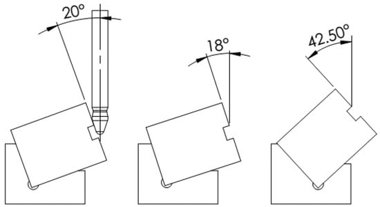
Figure 1.
Positioning of barrel tools in relation to the workpiece.
The rationale for selecting these specific angles (18°, 20°, and 42.5°) is based on the need to investigate the influence of varying the program angle on the machining process. Different angles will result in different orientations of the cutter relative to the machined surface, which can affect chip forces, surface quality, and productivity.
By using these cutters with varying angles, the aim is to optimize the machining parameters and adapt the barrel end-milling technology to the limitations imposed by the use of a 3-axis CNC machine.
3.2. Workpiece Material
For the realization of the milling tests with barrel end-milling cutters, the material chosen for the workpieces was titanium alloy (Ti-6Al-4V Grade 5, as specified in ISO 5832-3:2016 [35]), due to its mechanical properties and its relevance in industrial applications where barrel end-milling cutters are used.
For this purpose, the semi-manufactures used were parallelepipeds, a geometry selected to simplify machining operations, positioning during chipping and measurement of the resulting surfaces. More specifically, the machining program for machining with barrel end-milling cutters was developed using a semi-fabricated assembly consisting of a clamping pan and a titanium parallelepiped.
To ensure the accuracy and reproducibility of the results obtained from the processing of each specimen, strict adherence to the dimensions of the specimens was required. Accordingly, the titanium specimens were machined to a nominal length × width × height of 59.5 × 48 × 50 mm, with a dimensional tolerance of +0.05 mm after each dimension.
The Al7175 used to make the device is shown in Figure 2.
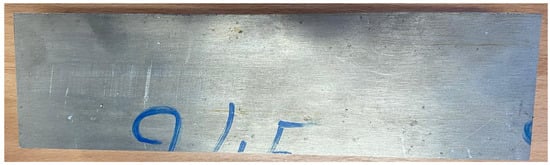
Figure 2.
Al7175 semi-finished product used to make the device.
Table 2 shows the chemical composition and mechanical characteristics of alloy 7175 according to the certificate.
Table 2.
Chemical composition and mechanical characteristics of alloy 7175.
3.3. Device Design
The device ensures a significantly higher rigidity of the semi-finished product compared to an additional axis attached to the CNC machine table or a manually operated dividing head. Such an axis can be purchased as an accessory for the CNC machine if it has been pre-equipped with an interface to drive additional axes.
Tests already performed with an additional axis, or a manual dividing head have indicated a significant decrease in rigidity and a pronounced negative influence on the obtained Ra (surface roughness).
The device was designed with the purpose of ensuring the optimal orientation of the semi-finished product (specimen) in relation to the programming angle of the barrel tool and the movement axes of the 3-axis CNC machine tool. An essential criterion in the device’s design was to ensure the rigid clamping of the semi-finished product during the machining process, to maintain stability and processing precision. Furthermore, the device was equipped with probing surfaces, integrated into the design to facilitate the precise definition of the device-specimen coordinate system, a system fundamental for the correct generation of the machining program.
The correct positioning of the semi-finished product is critical for each programming angle of the barrel tools. To ensure this positioning, the device was designed with an interchangeable locating element, adaptable to the specific programming angle. This approach allows for the use of a single fixture body with different locating jaws; each precisely machined for a specific barrel tool programming angle. Thus, the device allows for the orientation of the semi-finished product in accordance with the programming angles of the cutters used in the tests, namely 18°, 20°, and 42.5°.
Figure 3, Figure 4 and Figure 5 illustrate the 3D CAD models and assembly views of the device, highlighting the main components such as the vice, the jaw, and the specimen. These visual representations detail the assembly method of the components and the spatial relationships between them.
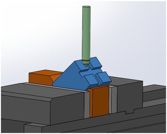
Figure 3.
Three-dimensional CAD assembly picture with vise—designed trough—test specimen—barrel end-milling cutter (programming angle 42.5°).
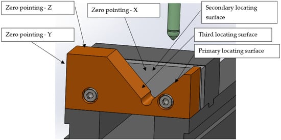
Figure 4.
CAD details of the locating jaw.
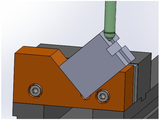
Figure 5.
Three-dimensional view of the assembled device.
Figure 3 presents a 3D CAD overview of the device, including the vice, the designed jaw, the specimen, and the barrel tool, with a programming angle of 42.5°.
Figure 4 provides a CAD detail of the locating jaw, a key component for positioning the specimen. It also indicates the locating, orienting, and supporting surfaces of the specimen, as well as the probing surfaces used during CAM programming. The listed surfaces are also important during the machining of the specimen by cutting.
Figure 5 shows a 3D view of the assembled device, giving a clear perspective of the final configuration.
It is important to note that the initial models (Figure 1) underwent modifications during the manufacturing process, with the addition of fixing holes to enhance the rigidity of the assembly and ensure a solid attachment to the fixed jaw of the vice.
The device utilizes a locating jaw, a component that orients the semi-finished product according to the specified programming angle. The angle of this jaw is directly dependent on the programming angle of the barrel tool.
Adequate clamping of the semi-finished product is a critical aspect for ensuring machining accuracy. The datums of the coordinate system used for machining and for designing the barrel tool’s path must be fixed in relation to the CNC machine tool (MUCN).
The device includes probing surfaces, which are essential for the precise definition of the coordinate system. These surfaces are used to establish the origin of the coordinate system required for the machining program.
Figure 6 illustrates the relative position of the cutter with respect to the semi-finished product during the machining operation.
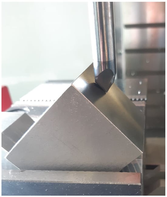
Figure 6.
Position of the barrel tool in relation to the blank.
3.4. Justification of Material Selection
To optimize the machining process, the material selected for the specimen locating jaw is a 7175 series aluminum alloy. This material was chosen due to its superior machinability, which facilitates machining operations, and its high hardness, which contributes to the stability and longevity of the device.
In the initial phase of the project, it was decided not to manufacture the locating jaw from steel. This decision was motivated by the need to first obtain confirmation of correct operation and validation of the proposed working methodology, before using a material that could have involved higher costs and increased processing complexity.
3.5. Device Manufacturing Process
The manufacturing process of the specimen support jaw was based on a rigorously structured technological route, ensuring a logical sequence of operations and efficient resource planning.
For each stage of the manufacturing process, the appropriate tools and tool holders were selected, and the corresponding cutting regimes were determined, to optimize the machining parameters and guarantee the achievement of the technical specifications.
For the execution of the specimen support jaw, a numerically controlled (CNC) machining technology was chosen, using a 3-axis Haas VF2 machine tool (Manufacturer: Haas Automation, Inc., City: Oxnard, Country: United States), selected for the precision and flexibility it offers in performing cutting operations.
To generate the control instructions for the machine tool, the specific toolpaths for each individual machining operation were developed using the MasterCAM 2024 software platform, which allows for a detailed definition of the trajectories and cutting parameters.
Figure 7, Figure 8 and Figure 9 detail the cutting tools used in the manufacturing process, and the figures illustrate the specific configuration of the tools and tool holders for various operations:
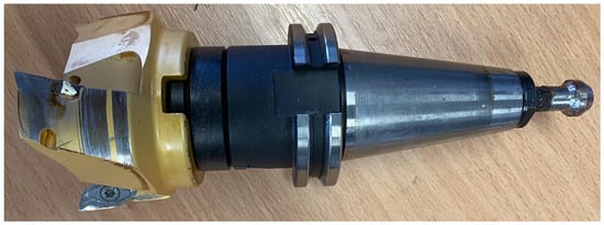
Figure 7.
Milling cutter and tool holder, used for surface planning.
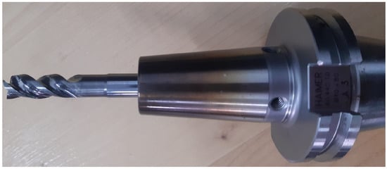
Figure 8.
Tool holder and solid carbide end mill (Ø10 mm, 3 flutes) for contouring and machining screw recesses.
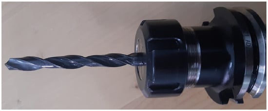
Figure 9.
HSS twist drill for drilling.
Figure 7 shows the cutter and tool holder used for the face milling operation.
Figure 8 shows the tool holder and the 10 mm diameter, 3-flute solid carbide end mill used for machining the contour and the counterbore recesses for the fixing screws.
Figure 9 shows the 9 mm diameter HSS twist drill used for machining the holes.
The following figures present the tool paths used in the manufacturing process.
Figure 10 graphically represents the operation of defining the workpiece, a preliminary step in the manufacturing process of the jaw. This definition involves specifying the geometric characteristics of the raw material, constituting a reference point for the subsequent processing stages.
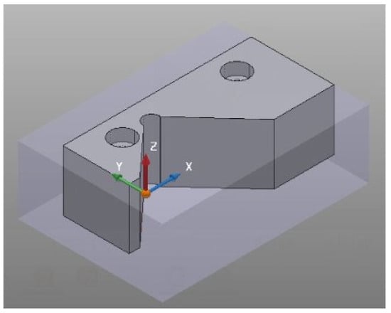
Figure 10.
Illustration of the workpiece definition process for manufacturing the support jaw.
Figure 11 shows the toolpaths generated for machining the jaw profile. These tool paths detail the relative movements of the cutting tool with respect to the workpiece, being essential for the control of the CNC machine tool and for achieving the final shape of the profile.
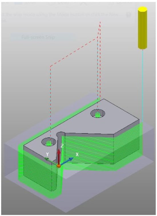
Figure 11.
Visualization of the toolpaths for machining the specimen support jaw profile.
Figure 12 illustrates the hole machining stage in the support jaw. This operation is necessary for creating the fastening or assembly elements of the jaw, and the precision and quality of the holes are essential for the functionality of the device.
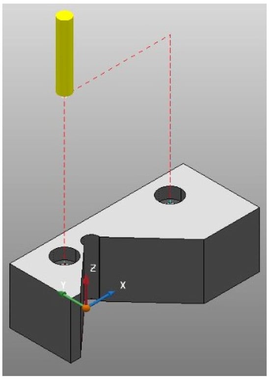
Figure 12.
Illustration of the drilling process for the support jaw.
Figure 13 illustrates the toolpaths used for the finishing stage of the jaw profile and for machining the recesses intended for cylindrical head screws. Profile finishing aims to achieve the specified dimensional accuracy and surface quality, and machining the recesses ensures the correct positioning of the assembly elements.
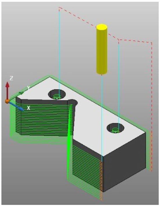
Figure 13.
Presentation of toolpaths for profile finishing and creating screw recesses in the jaw.
Figure 14 illustrates the parting-off operation, which consists of separating a portion of material from the semi-finished product. This operation, usually performed at the end of the machining process, contributes to obtaining the final geometry of the part by removing excess material.
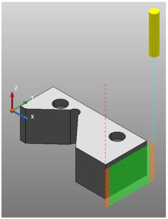
Figure 14.
Illustration of the parting-off stage in the manufacturing process of the jaw.
3.6. Actual Machining of the Support Jaw
Following the initial face milling operation, used to ensure a flat reference surface and a precise initial dimension of the semi-finished product, it was positioned and clamped using a vice (as can be seen in Figure 10). This preparatory stage was necessary to allow for the roughing operation of the locating jaw profile, an operation illustrated in Figure 11, through which excess material was removed to approach the final shape of the part.
Figure 15 presents the initial stage of the machining process, in which the semi-finished product is clamped in the vice to allow for the roughing operations. This precise and rigid clamping is essential for ensuring the stability of the semi-finished product during machining and for achieving the dimensional accuracy of locating jaw profile.
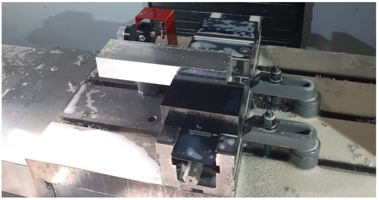
Figure 15.
Initial clamping of the semi-finished product in the vice for roughing.
Figure 16 details the clamping stage of the semi-finished product for the finishing operation of the profile. This finishing operation, which follows roughing, aims to achieve superior dimensional accuracy and surface quality. Adequate clamping of the semi-finished product is essential for ensuring the precision and quality of the finished profile.
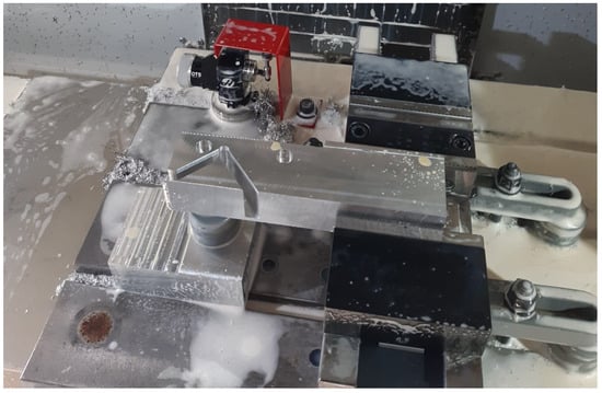
Figure 16.
Clamping of the semi-finished product in the vice for the finishing operation of the profile.
Figure 17 shows the support jaw after the machining process is complete, with the screws inserted into the specially created recesses. This image highlights the final geometry of the jaw, ready for assembly in the vice and for use within the specimen clamping device.
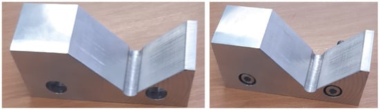
Figure 17.
Machined support jaw, with screws mounted, ready for assembly.
3.7. Inspection
To ensure the device’s conformity with the project specifications, rigorous metrological control was performed using a Hexagon RA-7312 3D measuring arm (Manufacturer: Hexagon Manufacturing Intelligence (a division of Hexagon AB), City: Stockholm (corporate headquarters of Hexagon AB), Country: Sweden). This coordinate measuring system, characterized by a precision of 5 µm + L/40 mm (where L is the length in mm), with a maximum permissible error of 18 µm, allowed for the precise evaluation of the device’s dimensional and geometric characteristics.
Figure 18 presents the experimental setup used for the control and validation of the support jaw.
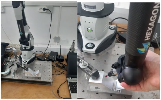
Figure 18.
Control setup for the inspection of the support jaw.
During this process, the relevant surfaces of the jaw were probed to determine the dimensional and positional deviations, which are critical for ensuring the correct positioning of the specimen during machining.
Figure 19 illustrates the experimental setup for the control of the support jaw-specimen assembly.
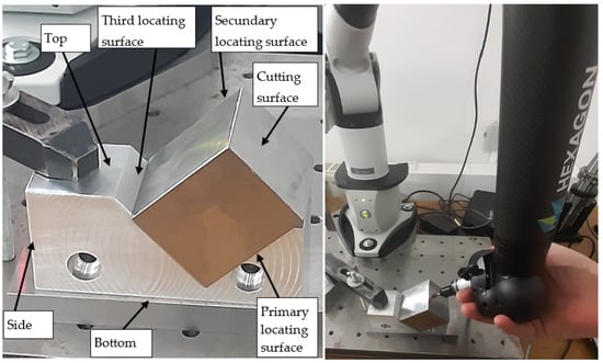
Figure 19.
Dimensional verification of the support jaw-specimen assembly.
- Primary locating surface: The surface on which the semi-finished product is positioned, thus defining the machining angle of the specimen.
- Third locating surface: An auxiliary reference surface used in the measurement process.
- Cutting surface: The surface of the specimen resulting from face milling, whose roughness will be evaluated after machining with the barrel tool.
- Programming angle: The angle between the side and cutting surfaces, representing the programming angle of the cutter.
- Complementary angle to programming angle: The angle between the bottom and cutting surfaces, used for verifying angular deviations.
- The control was focused on the key surfaces of the support jaw, those that directly influence the precision of the specimen’s positioning and, consequently, the programming angle of the barrel tool.
- The measured parameters included
- Surface flatness: The maximum deviation of each surface from the theoretical flatness, important for ensuring correct seating of the specimen and machining accuracy.
- Angular accuracy: The conformity of the machined angles with the designed nominal values, essential for adhering to the programming angle of the cutter.
- To ensure a correct interpretation of the results, a precise definition of the reference surfaces used in the measurements was made:
- Bottom: The base surface of the jaw parallel to the machine tool table plane.
- Side: The lateral surface of the jaw, perpendicular to the fixed jaw of the vice and the machine tool table. This surface defines the direction of the transverse feed and will be used as a reference for establishing the origin on the Y-axis during specimen machining.
- Top: The upper surface of the jaw, parallel to the machine tool table. This surface will serve as a reference for establishing the origin on the Z-axis.
- Secondary locating surface/Stationary Jaw: The surface that defines the direction of the longitudinal feed and will be used for establishing the origin on the X-axis.
3.8. Device Inspection Results
The validation of the designed device was carried out through a detailed metrological inspection using a Hexagon RA-7312 3D measuring arm. This procedure allowed for the quantification of the device’s dimensional deviations and the evaluation of its angular accuracy. Figure 20 shows a screenshot from the PC-DMIS 2024.1 software, illustrating the communication interface with the 3D measuring arm and the measurement results.
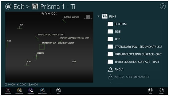
Figure 20.
PC-DMIS software interface, illustrating the data obtained from measurements with the 3D arm.
The flatness measurement results for the relevant surfaces of the device are presented below:
- Bottom: 0.003 mm
- Side: 0.008 mm
- Top: 0.002 mm
- Secondary locating surface/Stationary Jaw: 0.005 mm
- Primary locating surface: 0.004 mm
- Third locating surface: 0.007 mm
- Cutting surface: 0.012 mm
These flatness values, ranging from 0.002 mm to 0.012 mm, are all well within the specified nominal tolerance of 0.05 mm (as seen in Table 3), indicating a high degree of precision in the manufactured surfaces. This high flatness is essential for ensuring correct and stable seating of the workpiece, which directly contributes to machining accuracy.
Table 3.
Device inspection results.
The angular accuracy of the device was evaluated by measuring the programming angle and the complementary angle, obtaining the following values:
- Programming angle: 42.505°
- Complementary angle to Programming angle: 47.489° (angular deviation: 0.006°)
The measured programming angle of 42.505° and the complementary angle of 47.489° demonstrate an angular non-closure of merely 0.006°. This minimal deviation confirms the device’s exceptional capability to precisely orient the workpiece relative to the barrel cutter, which is essential for maintaining the correct programming angle throughout the machining process and achieving the desired surface geometry.
Table 3 summarizes the device inspection results, providing a clear overview of the dimensional and angular precision achieved.
The analysis of the obtained results indicates excellent conformity of the device with the designed specifications. As presented in this section and Table 3, the dimensional deviations of the surfaces are very small (e.g., surface flatness between 0.002 mm and 0.012 mm), suggesting precise manufacturing of the components and their correct assembly. Furthermore, the angular accuracy of the device is notably high, with an angular non-closure of only 0.006°, demonstrating its ability to position the semi-finished product with the necessary precision for machining with barrel tools. The observed deviations can be attributed to inherent errors in the manufacturing process, measurement uncertainties, and material variations, but their magnitude is considered minimal, having a negligible impact on machining accuracy for the intended applications.
Based on the results obtained, the following aspects can be stated:
- The device positioned the workpiece with small dimensional deviations, indicating good accuracy in achieving the designed geometry.
- The angular accuracy of the device was also high, with an angular non-closure of only 0.006°.
- The sources of deviations can be attributed to manufacturing errors, measurement errors, or material variations.
- The impact of the deviations on machining accuracy is considered minimal, given their small values.
3.9. Discussions
While the designed device’s dimensional and angular accuracy was rigorously validated through metrological inspection, providing sufficient evidence for its intended application in cutting tool and cutting regime studies, a detailed Finite Element Method (FEM) analysis of the fixture’s vibration and stiffness characteristics was not within the primary scope of this initial research. The current study focused on demonstrating a practical and economical solution for enabling barrel milling on 3-axis CNC machines by ensuring precise workpiece orientation and rigid clamping.
This research successfully aimed to design and validate a specialized device for enabling machining of inclined planes with barrel tools on a 3-axis CNC machine. The specific objectives included novel design, ensuring adaptability, and validating the device’s performance. The results obtained from the verification, which demonstrated minimal dimensional deviations and high angular accuracy, confirm the achievement of the proposed objectives and highlight the device’s innovative capability to precisely orient the semi-finished product—an essential aspect for the efficient use of barrel tools on a 3-axis CNC machine, which was previously a significant challenge.
Existing solutions for machining with barrel tools frequently involve the exclusive use of 5-axis CNC machines, which can limit accessibility and significantly increase costs. This research presents a novel and viable alternative for situations where only 3-axis machines are available. The designed device ensures precise positioning of the semi-finished product, effectively compensating for the limitations imposed by 3-axis machines and enabling accurate results in machining with barrel tools, a capability not typically associated with these simpler platforms. The advantages of the device include adaptability to different programming angles, rigid clamping of the semi-finished product, and the integration of probing surfaces to facilitate the definition of the coordinate system. Figure 21 illustrates the jaw fixed in the vice, with and without the semi-finished product.
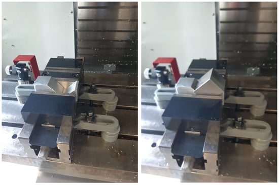
Figure 21.
Jaw fixed in the device with and without the specimen (sample).
The research presents certain limitations, such as the dependence on a specific type of machine tool and the necessity of using a specific device for each programming angle. To overcome these limitations, future research directions could include
- Automating the changing of locating elements for different programming angles, which would increase the flexibility and efficiency of the device.
- Designing a universal device, adaptable to a wider range of programming angles without requiring component changes, which would reduce complexity and costs.
- Integrating sensors for monitoring cutting forces and optimizing machining parameters, which would allow for more precise control of the machining process and an improvement in surface quality.
- Extending the research to include machining tests with different materials and barrel tools, to evaluate the device’s performance under various conditions and identify optimal machining parameters.
- Performing advanced simulations, such as Finite Element Method (FEM) analysis, to thoroughly evaluate the fixture’s vibration and stiffness characteristics under various cutting conditions, thereby enabling further structural optimization.
4. Device Validation
After the manufacturing and control of the clamping device, a technological assembly testing phase followed, aimed at testing and studying the behavior of barrel tools during the machining of titanium alloys.
In this validation stage of the enunciated and practically implemented idea, we test the workpiece (semi-finished product) clamping device, the barrel end mill clamping, the machining program toolpaths, the depth of cut ap, the stepover ae, the feed per tooth fz, and the CNC machine feed, the cutting speed and the cutting tool rotation speed.
The established working principle involves measuring each sample before machining with the barrel end mill. This is performed on a stand equipped with a dial indicator with a measuring accuracy of 0.01 mm.
Figure 22 presents the workpiece measuring assembly. Using a digital indicator, in the first stage, calibration to zero is performed using two gauge blocks of 50 mm and 8 mm. Then, when placing the workpiece to be measured, the indicated value is added to the 58 mm dimension. This procedure is shown in Figure 23. In this case, the height of the workpiece to be machined is 59.53 mm.
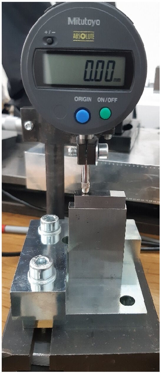
Figure 22.
Specimen height measurement setup before processing.
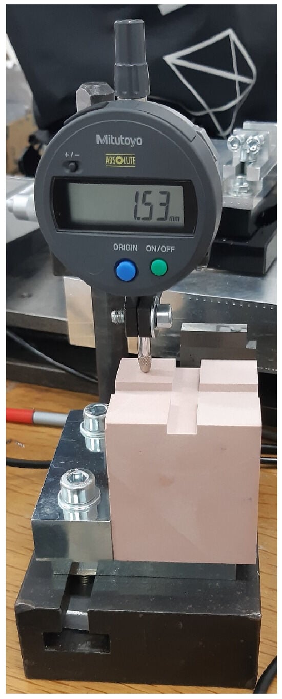
Figure 23.
Digital comparator calibration procedure and specimen height measurement.
For the first test, the workpiece material was chosen as SikaBlock M700 (Manufacturer: Sika AG, City: Baar, Country: Switzerland), an easily machinable polyurethane resin, to protect the tool and the other elements of the technological assembly in case of an error.
The chosen cutting tool is a 12 mm diameter barrel end mill with 3 flutes, model 3540L.12200A, manufactured by Emuge Franken (Manufacturer: Emuge Franken GmbH, City: Lauf an der Pegnitz, Country: Germany) (Figure 24).
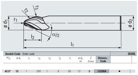
Figure 24.
The chosen cutting tool.
The machining program was created in MasterCAM. The toolpath can be seen in Figure 25.
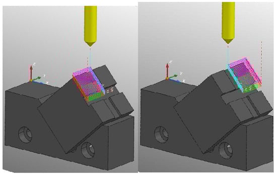
Figure 25.
Toolpath generated in MasterCAM for milling tests.
The program is written for two upper surfaces of the workpiece positioned according to the 42.5 programming angle so that the cutting tool starts from the median channel and moves towards the end of the workpiece. In this way, we can compare climb milling with conventional milling. After machining the front surface (conventional milling), the rear surface is machined (climb milling). These stages are shown in Figure 26 and Figure 27.
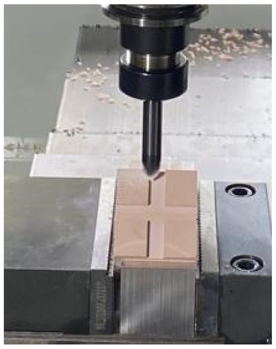
Figure 26.
Machining the front surface of the specimen (conventional milling).
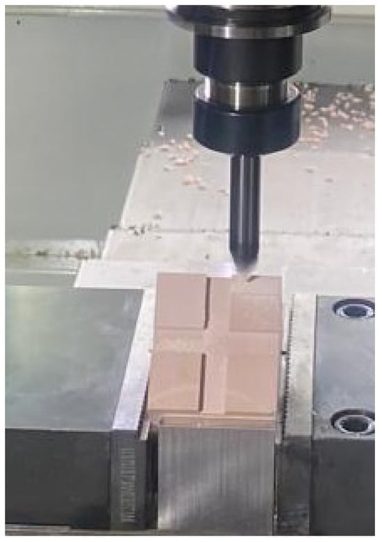
Figure 27.
Machining the back surface of the specimen (climb milling).
A workpiece was machined, and the program was stopped at an intermediate stage (Figure 28) to visualize the trace left by the cutting tool during machining. The tool’s profile was studied using a Garant MM1 200 measuring microscope (Figure 29). Following the measurements, a depth of cut ap = 0.115 mm was measured.
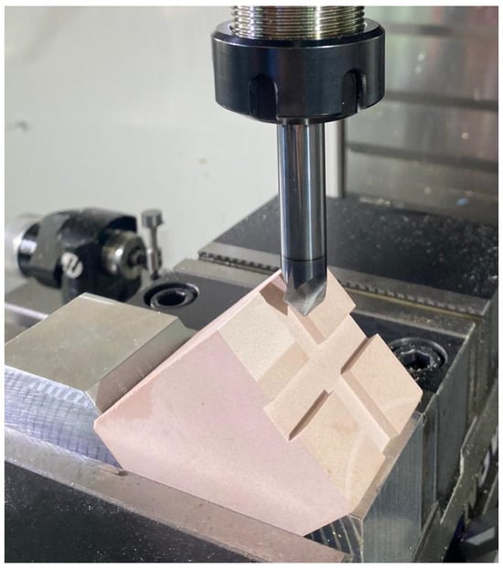
Figure 28.
Partially machined specimen, used for visualizing the cutting tool mark.
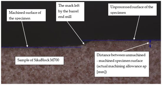
Figure 29.
Barrel End Mill Profile: Characteristic Radii (r1 and r2).
The machining program was written for a depth of cut ap = 0.1 mm. The difference of 0.015 mm represents cumulative errors, a value that will be considered when machining the titanium alloy workpieces.
Figure 29 shows the two specific radius of the barrel end mill profile: the tip radius r1 = 1 mm and the flank radius r2 = 200 mm.
5. Conclusions
This research successfully investigated the possibility of effectively using barrel tools on 3-axis CNC machines by designing and validating a pioneering specialized device. The designed device uniquely ensures the precise orientation of the semi-finished product in relation to the barrel tool, thereby fundamentally overcoming the limitations inherent to 3-axis CNC machines for this advanced machining technique. The validation of the device, through detailed metrological inspection using a Hexagon RA-7312 3D measuring arm (as presented in Section 3.8), demonstrated high dimensional and angular accuracy. Specifically, surface flatness values were between 0.002 mm and 0.012 mm, and angular non-closure was merely 0.006°, indicating its effectiveness and precision in positioning the workpiece for machining with barrel tools.
The designed device proved to be effective in enabling the machining of inclined planes with barrel tools on a 3-axis CNC machine. By using an interchangeable locating element, the device can be adapted for different programming angles of the barrel tools. The validation results indicate that the device ensures precise positioning of the semi-finished product, compensating for the limitations imposed by the lack of additional machine tool axes and allowing for accurate results.
This paper presents an innovative method to extend the applications of barrel tools to 3-axis CNC machines, which are significantly more accessible and widespread in industry. The designed device provides a breakthrough solution that can be utilized in various industrial applications requiring the machining of complex surfaces, such as in the aerospace industry, the automotive industry, or mold production, contributing significantly to the optimization of machining processes and the reduction in production costs by making advanced techniques more broadly available.
To extend the applicability and efficiency of the proposed method, further research directions could include
- Evaluating the performance of the device with different materials and barrel tools.
- Integrating sensors for monitoring and optimizing cutting parameters.
- Automating the process of changing locating elements.
- Designing a universal device, adaptable to a wide range of programming angles.
- Conducting Finite Element Method (FEM) analysis to further optimize the fixture’s structural performance and dynamic behavior.
Author Contributions
Conceptualization, S.R.-N. and A.B.P.; methodology, S.R.-N. and A.B.P.; software, S.R.-N. and A.B.P.; validation, S.R.-N., A.B.P. and A.M.T.; formal analysis, A.B.P. and A.M.T.; investigation, S.R.-N. and A.B.P.; resources, A.B.P. and S.R.-N.; data curation, A.B.P. and S.R.-N.; writing—original draft preparation, A.B.P. and S.R.-N.; writing—review and editing, A.B.P. and A.M.T.; visualization, S.R.-N., A.B.P. and A.M.T.; supervision, A.B.P. and S.R.-N.; project ad-ministration, A.B.P.; funding acquisition, A.B.P. All authors have read and agreed to the published version of the manuscript.
Funding
This research was funded by the Technical University of Cluj-Napoca, through the pro-ject “Development of Advanced Technologies with Barrel End-Mills for Efficient Machining of Titanium Alloys in Aeronautics” (ID 1508), project number 28/01-07-2024, awarded via the National Grant Competition—GNaC ARUT 2023. The APC was funded by the Technical University of Cluj-Napoca.
Institutional Review Board Statement
Not applicable.
Informed Consent Statement
Not applicable.
Data Availability Statement
Data are contained within the article.
Acknowledgments
This work was supported by the “Development of Advanced Technologies with Barrel End-Mills for Efficient Machining of Titanium Alloys in Aeronautics” grant funded by the National Grant Competition—GNaC ARUT 2023.
Conflicts of Interest
The authors declare no conflicts of interest.
References
- Pelayo, G.U.; Olvera-Trejo, D.; Luo, M.; De Lacalle, L.L.; Elías-Zuñiga, A. Surface roughness prediction with new barrel-shape mills considering runout: Modelling and validation. Measurement 2021, 173, 108670. [Google Scholar] [CrossRef]
- Pop, A.B.; Ravai-Nagy, S.; Titu, A.M.; Medan, N.; Filip, A.C. Recent Contributions to the Development of Barrel End-Mill Machining Technologies for Titanium Alloys in the Aerospace Context. Aerospace 2025, 12, 55. [Google Scholar] [CrossRef]
- Zhou, Y.; Jiang, Y.; Lu, C.; Huang, J.; Pei, J.; Xing, T.; Zhao, S.; Zhu, K.; Yan, H.; Xu, Z.; et al. A review of 5-axis milling techniques for centrifugal impellers: Tool-path generation and deformation control. J. Manuf. Process. 2024, 131, 160–186. [Google Scholar] [CrossRef]
- Jiang, Y.; Guo, M.; Du, G.; Wei, Z. Cutting dynamics research on the five-axis machining of thin curved surface with barrel-taper-ball milling cutter. Int. J. Adv. Manuf. Technol. 2024, 131, 3905–3919. [Google Scholar] [CrossRef]
- Khorasani, M.; Ghasemi, A.H.; Farabi, E.; Leary, M.; Gibson, I.; Rolfe, B. A comprehensive investigation of abrasive barrel finishing on hardness and manufacturability of laser-based powder bed fusion hollow components. Int. J. Adv. Manuf. Technol. 2022, 120, 3471–3490. [Google Scholar] [CrossRef]
- Shi, H.; Li, X.; Yang, S.; Zhao, R.; Yuan, X. Analysis of Chemical Oxygen Demand in Barrel Finishing Based on Reusing Water Resource of Grinding Fluid. Materials 2024, 17, 4051. [Google Scholar] [CrossRef]
- Żurawski, K.; Żurek, P.; Kawalec, A.; Bazan, A.; Olko, A. Modeling of Surface Topography after Milling with a Lens-Shaped End-Mill, Considering Runout. Materials 2022, 15, 1188. [Google Scholar] [CrossRef]
- Suzuki, T.; Okamoto, K.; Morishige, K. Tool path generation for five-axis controlled machining of free-form surfaces using a barrel tool considering continuity of tool postures. Int. J. Autom. Technol. 2021, 15, 885–892. [Google Scholar] [CrossRef]
- Uchida, S.; Oyaizu, N.; Nakagawa, M.; Hirogaki, T.; Aoyama, E. Investigation of Machining Condition for Barrel End Mill Based on Data-Mining Method for Tool Catalog Database. Key Eng. Mater. 2025, 1008, 49–55. [Google Scholar] [CrossRef]
- Artetxe, E.; Urbikain, G.; Lamikiz, A.; López-de-Lacalle, L.N.; González, R.; Rodal, P. A mechanistic cutting force model for new barrel end mills. Procedia Eng. 2015, 132, 553–560. [Google Scholar] [CrossRef]
- Urbikain, G.; Artetxe, E.; de Lacalle, L.N.L. Numerical simulation of milling forces with barrel-shaped tools considering runout and tool inclination angles. Appl. Math. Model. 2017, 47, 619–636. [Google Scholar] [CrossRef]
- López de Lacalle, L.N.; Lamikiz, A.; Muñoa, J.; Salgado, M.A.; Sánchez, J.A. Improving the high-speed finishing of forming tools for advanced high-strength steels (AHSS). Int. J. Adv. Manuf. Technol. 2006, 29, 49–63. [Google Scholar] [CrossRef]
- Bo, P.; Fan, H.; Bartoň, M. Efficient 5-axis CNC trochoidal flank milling of 3D cavities using custom-shaped cutting tools. Comput.-Aided Des. 2022, 151, 103334. [Google Scholar] [CrossRef]
- Tsai, C.Y. Optimum error design and 5-axis CNC machining of preloaded roller-gear-cam in roller-drive system. Measurement 2025, 241, 115715. [Google Scholar] [CrossRef]
- Lu, F.; Zhou, G.; Zhang, C.; Liu, Y.; Chang, F.; Lu, Q.; Xiao, Z. Energy-efficient tool path generation and expansion optimisation for five-axis flank milling with meta-reinforcement learning. J. Intell. Manuf. 2024. [Google Scholar] [CrossRef]
- Marin, F.; de Souza, A.F.; da Silva Gaspar, H.; Calleja-Ochoa, A.; de Lacalle, L.N.L. Topography simulation of free-form surface ball-end milling through partial discretization of linearised toolpaths. Eng. Sci. Technol. Int. J. 2024, 55, 101757. [Google Scholar] [CrossRef]
- Liang, F.; Kang, C.; Fang, F. A review on tool orientation planning in multi-axis machining. Int. J. Prod. Res. 2021, 59, 5690–5720. [Google Scholar] [CrossRef]
- O’Toole, L.; Kang, C.W.; Fang, F.Z. Precision micro-milling process: State of the art. Adv. Manuf. 2021, 9, 173–205. [Google Scholar] [CrossRef]
- Jarosz, K.; Chen, Y.T.; Liu, R. Investigating the differences in human behavior between conventional machining and CNC machining for future workforce development: A case study. J. Manuf. Process. 2023, 96, 176–192. [Google Scholar] [CrossRef]
- Li, R.; Xin, M.; Wu, J.; Kong, B. Influence of material selection on fixture accuracy of CNC machine tools. J. Phys. Conf. Ser. 2021, 1986, 012029. [Google Scholar] [CrossRef]
- Kaliński, K.J.; Stawicka-Morawska, N.; Galewski, M.A.; Mazur, M.R. A method of predicting the best conditions for large-size workpiece clamping to reduce vibration in the face milling process. Sci. Rep. 2021, 11, 20773. [Google Scholar] [CrossRef]
- Liu, W.; Zhang, S.; Lin, J.; Xia, Y.; Wang, J.; Sun, Y. Advancements in accuracy decline mechanisms and accuracy retention approaches of CNC machine tools: A review. Int. J. Adv. Manuf. Technol. 2022, 121, 7087–7115. [Google Scholar] [CrossRef]
- Ab Wahab, N.; Adlin, N.; Nassiruddin, M.A.A.; Yaakob, M.Y.; Bakar, M.H.A.; Sani, M.A.M.; Rahman, I.U. Impact of Vacuum Clamping System Designs on Surface Quality During the End Milling Process. Malays. J. Microsc. 2024, 20, 121–132. [Google Scholar]
- Ullah, A.; Chan, T.C.; Xie, Z.Y. Improving CNC Turning Machine Precision through Vibration Analysis for Clamping Error Detection Employing Principal Component Analysis. Res. Sq. 2024. [Google Scholar] [CrossRef]
- Du, X.; Liu, S.; Jin, S. Distribution analysis of deterministic clamping and positioning error for machining of ring-shaped workpieces considering alignment uncertainty. Int. J. Adv. Manuf. Technol. 2024, 131, 3921–3936. [Google Scholar] [CrossRef]
- Zhang, Z.; Yang, Y.; Li, G.; Qi, Y.; Yue, C.; Hu, Y.; Li, Y. Machining accuracy reliability evaluation of CNC machine tools based on the milling stability optimization. Int. J. Adv. Manuf. Technol. 2023, 124, 4057–4074. [Google Scholar] [CrossRef]
- Nguyen, D.K.; Huang, H.C.; Feng, T.C. Prediction of Thermal Deformation and Real-Time Error Compensation of a CNC Milling Machine in Cutting Processes. Machines 2023, 11, 248. [Google Scholar] [CrossRef]
- Ivanov, V.; Botko, F.; Dehtiarov, I.; Kočiško, M.; Evtuhov, A.; Pavlenko, I.; Trojanowska, J. Development of flexible fixtures with incomplete locating: Connecting rods machining case study. Machines 2022, 10, 493. [Google Scholar] [CrossRef]
- Kovalev, A.A.; Pobedinskii, A.V.; Rogov, N.V. Strategies for Optimal Technological Base Selection in CNC Machining Process Design for Machine Casing Components. J. Mach. Manuf. Reliab. 2024, 53 (Suppl. 1), S66–S79. [Google Scholar] [CrossRef]
- Ismartaya, K.; Wijaya, T.G.; Purnomo, R.; Karyadi, G.B. Design and Manufacture of Automatic Collet Clamping Systems for Sprocket-CAM Handling on CNC Lathes. SINTEK J. J. Ilm. Tek. Mesin 2024, 18, 99–112. [Google Scholar] [CrossRef]
- Weckx, S.; Robyns, S.; Baake, J.; Kikken, E.; De Geest, R.; Birem, M.; Maes, D. A cloud-based digital twin for monitoring of an adaptive clamping mechanism used for high performance composite machining. Procedia Comput. Sci. 2022, 200, 227–236. [Google Scholar] [CrossRef]
- Aphale, S.; Nandurdikar, V.; Desale, S. Design and deployment of fixture on assembly line to improve productivity. J. Phys. Conf. Ser. 2021, 1803, 012025. [Google Scholar] [CrossRef]
- Campi, F.; Favi, C.; Germani, M.; Mandolini, M. CAD-integrated design for manufacturing and assembly in mechanical design. Int. J. Comput. Integr. Manuf. 2022, 35, 282–325. [Google Scholar] [CrossRef]
- Artetxe, E.; Olvera, D.; de Lacalle, L.N.L.; Campa, F.J.; Olvera, D.; Lamikiz, A. Solid subtraction model for the surface topography prediction in flank milling of thin-walled integral blade rotors (IBRs). Int. J. Adv. Manuf. Technol. 2017, 90, 741–752. [Google Scholar] [CrossRef]
- ISO 5832-3:2016; Implants for Surgery—Metallic Materials—Part 3: Wrought Titanium 6-aluminium 4-vanadium Alloy. International Organization for Standardization: Geneva, Switzerland, 2016.
Disclaimer/Publisher’s Note: The statements, opinions and data contained in all publications are solely those of the individual author(s) and contributor(s) and not of MDPI and/or the editor(s). MDPI and/or the editor(s) disclaim responsibility for any injury to people or property resulting from any ideas, methods, instructions or products referred to in the content. |
© 2025 by the authors. Licensee MDPI, Basel, Switzerland. This article is an open access article distributed under the terms and conditions of the Creative Commons Attribution (CC BY) license (https://creativecommons.org/licenses/by/4.0/).