Article

Research on the Bearing Characteristics of Narrow Coal Pillars in Double-Roadway Excavation Under the Influence of Full Dynamic Pressure

State Key Laboratory of Coal Resources and Safe Mining, China University of Mining and Technology, Xuzhou 221116, China
*
Authors to whom correspondence should be addressed.
Appl. Sci. 2025, 15(13), 7148; https://doi.org/10.3390/app15137148
Submission received: 2 June 2025 / Revised: 13 June 2025 / Accepted: 24 June 2025 / Published: 25 June 2025
(This article belongs to the Section Civil Engineering)

Abstract

A narrow coal pillar in double-roadway excavation can solve the problem of working face connection and improve the resource recovery rate, but narrow coal pillars are affected by the full mining stress. Taking the 2109 double-roadway excavation of Qingwa Coal Mine as the engineering background, the roof mechanical structure model of a narrow coal pillar in a double-roadway excavation layout was established, and the bearing characteristics of different coal pillar widths under the influence of full dynamic pressure were studied. The narrow coal pillar retention width was obtained and tested through field industrial experiments. The main research results were as follows: (1) The relationship between the coal pillar bearing load and the immediate roof length was deduced, and the bearing stress of the coal pillar was divided into the steep decline stage, the transition stage, and the stabilization stage. The coal pillar within the width of the stabilization stage has a certain strength surplus capacity. (2) Under the influence of full dynamic pressure, the 5~7 m coal pillar yielded to failure, and the coal pillar of 8 m and above had a certain residual bearing capacity, compared with the first mining. After the second mining, the elastic zone in the coal pillar of each width was significantly reduced; there was no elastic grid in the coal pillar of 5 m and 6 m in width, and the grid area and proportion of the elastic zone of the coal pillars with widths of 7 m and above were very low. The optimal retention width of the narrow coal pillar was determined to be 8 m. (3) Under the influence of repeated mining, the impact of first mining on the roadway displacement of the roof and floor plate was greater, followed by the solid coal side, which had less impact on the coal pillar side. The secondary mining had a greater impact on the floor, followed by the coal pillar side and the solid coal side, which had little impact on the roadway roof. This paper also provides a significant reference for the retention of narrow coal pillars in double-roadway excavation.

1. Introduction

Due to China’s energy status of “lack of oil, lack of gas, and relative abundance of coal”, coal will remain the main energy source for a long time [1,2,3]. When the upper face is mined, it is necessary to wait for the goaf subjected to caving to completely stabilize before the roadway excavation of the next working face, which often needs a waiting period of 3~10 months. In order to alleviate the problem of a lack of mining continuity, the method of skipping mining is often used in many mines, but this will lead to the impact of excessive island stress during working face mining [4,5,6,7]. In order to improve production efficiency, many mines often use double-roadway excavation [8,9,10].
Wang Meng et al. [11] conducted a comprehensive study using the Yushuling Coal Mine as a geological case study, which focused on analyzing the advantages and disadvantages of various roadway layouts. They proposed an innovative roadway layout termed narrow coal pillar in double-roadway excavation (NCPDRE). This approach demonstrates significant potential in reducing mining stress and improving working face recovery rates. Their study further examined the impact of roof tunneling parameters and pillar width on the stability of narrow coal pillars. Bai Wenyong et al. [12] employed limit equilibrium theory to calculate the optimal width range for narrow coal pillars. Numerical simulations were conducted to analyze the vertical stress and plastic zone of coal pillars under first mining. The reasonable coal pillar width was 8 m. Huang et al. [13] developed a mechanical model for the overlying rock layer in the NCPDRE and then calculated the bearing stress of small coal pillars, which was determined to be 7 m. He Yanjun et al. [14] investigated stress distribution patterns in coal pillars at varying mining distances, observing a transition from single-peak distribution to bimodal symmetrical distribution in stress curves as mining distances increased. Zhang Shoubao et al. [15] investigated the stress–displacement relationship of surrounding rock in double-roadway excavation under deep high-stress conditions and revealed that rock deformation primarily manifests as deformation in the two sides of the roadway, accompanied by subtle asymmetric failure patterns. Chen Li et al. [16] focused on the formation mechanisms and influencing factors of strong dynamic pressure during double-roadway excavation. Qian Deyu et al. [17] analyzed the evolutionary patterns of roadway stress under full mining conditions, subsequently proposing comprehensive surrounding rock control strategies, including self-moving hydraulic support systems, large-diameter borehole pressure relief techniques, and long anchor cable installations on the roof. Liu Shuaigang et al. [18] employed UDEC numerical simulation to examine coal pillar failure characteristics during double-roadway excavation, demonstrating that, under the influence of repeated mining, internal failure rates of coal pillars reached 90%, indicating a complete failure state. Han Bingcheng et al. [19] utilized numerical simulation software to investigate roof transportation mechanisms during double-roadway excavation in thick coal seams. Based on internal stress field theory, a formula for determining the distribution range of internal stress fields during roof cutting and pressure relief operations was derived. Wu Xiangye et al. [20,21,22,23] conducted a comprehensive investigation on the plastic zone and deviator stress distribution patterns in double-roadway spacing within surrounding rock formations and revealed a significant transformation in failure patterns, with the plastic zone gradually transitioning from an asymmetric to symmetric failure as the distance increased. The magnitude of deviator stress and its angle of application were identified as primary contributors to asymmetric roadway failure. Furthermore, they proposed a novel conceptual framework wherein the roadway’s plastic zone could be interpreted as the superposition of primary and secondary mining plastic zones and established comprehensive expansion patterns and discrimination methodologies for plastic zones under repeated mining influences.
Coal pillars in double roadways are subjected to the influence of full mining dynamic stresses from excavation, the first working face mining, and the next working face mining, which poses a great challenge to the stability of coal pillars and the control of the surrounding rock [24,25,26,27]. Therefore, in this study, we took the double-roadway coal pillar between working faces 2109 and 2110 in the No.2 coal seam of Qingwa Mine as the research object. Using mechanical model construction, numerical simulation, and on-site industrial experiments, research was performed on the bearing characteristics of the NCPDRE under the influence of the full dynamic pressure, and then a reasonable narrow coal pillar width was determined for the double-roadway excavation of the No.2 coal seam in Qingwa Mine.

2. Regional Engineering Background

Shanxi Jinmei Group Yicheng Shengtai Qingwa Coal Mine Co., Ltd., is located in the east of Shihe Village, Xiyan Town, Yicheng County, Linfen City, Shanxi Province. The 2109 working face of Qingwa Mine is shown in Figure 1a,b, with the 2110 working face in the north, the 2017 goaf zone in the south, the boundary protection coal pillar of the well field’s air-mining zone in the west, and the roadway of the disc area in the east, as shown in Figure 1d. The mining depth of the 2109 working face is 220 m, the coal seam’s thickness ranges from 3.4 m to 4.4 m, and the average thickness of the coal seam is 3.9 m; the angle of inclination of the coal seam ranges from 3.32° to 7°, with an average of 5.16°. The working face is arranged in the shape of a ‘knife handle’. The net width of section I is 65 m, and the net advancing length is 205.688 m, whereas the net width of section II is 115 m, and the net advancing length is 365.349 m. The coal seam thickness of the 2110 working face is 3.4 m~4.41 m, with an average thickness of 3.9 m, and the width of the mined area and the advancing length are 100 m and 230 m, respectively. The method of comprehensive caving coal mining is used for working face excavation, with a mining height of 2.6 m and a coal caving height of 1.3 m. The ratio of mining to caving is 1:0.5, and the roof is managed using the fallen method. The mining step is 0.6 m, and the mining speed is 2.4 m per day, using a single round of the interval-group coal caving method.
The histogram of the 2109 working face is shown in Figure 1c. The main roof of the working face is mudstone, 3.25 m thick, black-gray, thick-layered, and dense, with no fracture development. The immediate roof is siltstone, 4.43 m thick, black-gray, rich in plant fossils, and with no crack development. The immediate floor is mudstone, 1.5 m thick, dark gray, rich in plant fossils, and with no fissures. The main floor is siltstone, 7.0 m thick, gray-black, rich in plant fossils, and with no fissures.

3. Theoretical Calculation of the Narrow Coal Pillar Width for Double-Roadway Excavation
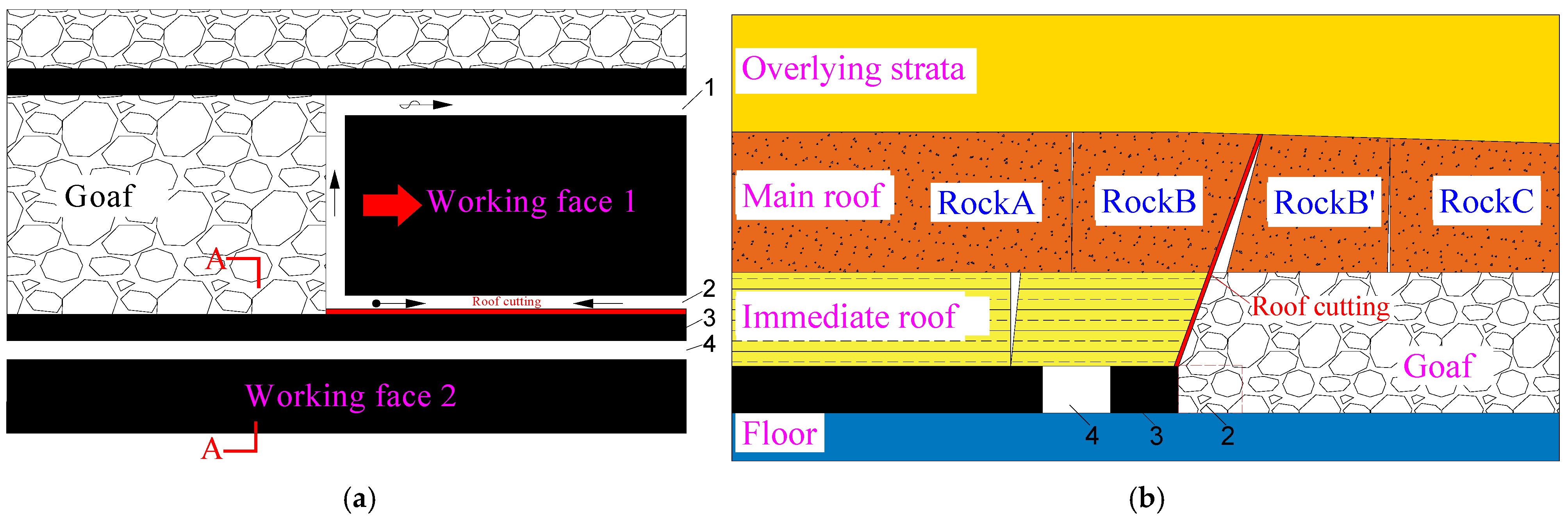
3.1. NCPDRE Layout

The layout of NCPDRE is shown in Figure 2. When arranging the preparation roadway of working face 1, the return-air roadway of working face 1 and the transport roadway of working face 2 of the next section are excavated at the same time, and a certain width of coal pillar is left between the two roadways. The return-air roadway of the next section does not serve as the working face in this section, but only to alleviate the difficulties of the successive mining and excavation of the mine. In the mining process of working face 1, the overburden roof in the goaf side will be cut off by blasting, hydraulic fracturing, and other methods to avoid the influence of lateral support pressure on the roadway of the next section’s working face 2 after the mining of working face 1 [13].
On the one hand, the NCPDRE is adopted using the gob-side entry retaining technology to arrange the roadway in a good stress environment and improve the recovery rate as much as possible, and on the other hand, it can further weaken the overburden pressure by the automatically formed roadway as a result of roof cutting [28,29,30]. In terms of the stress environment and deformation stage of the roadway, in the NCPDRE, the overall mining dynamic pressure of roadway excavation, upper working face mining, and next working face mining play a crucial role, and roadway deformation also has corresponding stages. By leaving a narrow coal pillar, the roadway is arranged in the area with less supporting stress, and the suspended roof of the upper working face is intercepted by the mode of roof cutting pressure relief, which weakens the transmission effect of the supporting stress on the roadway and ensures a good stress environment for the roadway. In order to further improve the resource recovery rate and achieve continuous mining of Qingwa Mine, it is necessary to research the reasonable width of the coal pillar under this arrangement.

3.2. Mechanical and Structural Modeling of the Immediate Roof

According to the overburden rock structure of the working face in the upper section, the mechanical structure model of the immediate roof of this section was established, as shown in Figure 3 below. The overburden rock cannot completely fill the goaf when the roof is not cut; therefore, the force of the goaf gangue on the roof was ignored in this model.
Here, q0 is the load of the overlying rock strata; x0 is the plastic zone width of the roadway, and σy is the supporting pressure of the coal rib. d is the width of the roadway, and q1 is the support resistance; Bc is the coal pillar width, and q2 is the bearing load of the coal pillar to the roof; l is the immediate roof length in the goaf.
According to the static equilibrium conditions, F x = 0 ;   F y = 0 ;   M o = 0 . The equilibrium equation is as follows:
F x = F o x = 0 F y = q 0 x 0 + d + B c + l F o y 0 x 0 σ y d x q 1 d q 2 B c = 0 M o = 1 2 q 0 x 0 + d + B c + L 2 + M 0 x 0 σ y x d x q 1 d x 0 + 1 2 d q 2 B c x 0 + d + 1 2 B c = 0
where Fx is the resultant force of the mechanical model in the x-direction, Fy is the resultant force of the mechanical model in the y-direction, and Mo is the resultant moment of the mechanical model at the origin O. Fox and Foy are the binding forces of the fixed end constraint along the x and y directions; M is the binding force couple of the fixed end constraint.
The x0 can be calculated as follows:
x 0 = m A 2 t a n φ 0 l n k γ H + C 0 / t a n φ 0 C 0 / t a n φ 0 + P x / A
where m is the mining height of the coal seam, m; A is the lateral pressure coefficient of the mine; φ0 is the internal friction angle of the contact surface between the coal seam and the upper and lower slabs, °; k is the stress concentration coefficient in the coal body; γ is the average capacity of the overlying rock layer, N/m3; H is the depth of burial of the coal seam, m; C0 is the adhesion of the contact surface between the coal seam and the top and bottom slabs, MPa; and Px is the load-bearing capacity of the coal wall, MPa.
In this model, the roadway support pressure was assumed as linearly distributed, and the immediate roof was regarded as an elastomer. The linear distribution of stress was more consistent. This was also beneficial to the integral calculation in this study. The supporting stress function of the constructed coal rib on the immediate roof was determined as follows [31]:
σ y = k γ H ( 1 x x 0 ) ,   0 x x 0
For the sake of subsequent simple calculations, the integral part of the mechanical equilibrium equation was calculated in advance:
F 1 = 0 x 0 σ y d x = 1 2 k γ H x 0 ;   M 1 = 0 x 0 σ y x d x = 1 6 k γ H x 0 2
According to the equilibrium equation, the constrained reaction force at the fixed end can be calculated as follows:
F o x = 0 F o y = q 0 x 0 + d + B c + l F 1 q 1 d q 2 B c M = M 1 + q 1 d x 0 + 1 2 d + q 2 B c x 0 + d + 1 2 B c 1 2 q 0 x 0 + d + B c + l 2
For rectangular beams, the maximum bending moment that the plate can withstand is shown in the following equation:
M m a x = h 2 6 R t
where h is the thickness of the immediate roof, m; Rt is the tensile strength of the immediate roof, MPa. Based on this, the relationship between the coal pillar supporting load and the length of the immediate roof was established as follows:
q 2 = 3 q 0 x 0 + d + B c + L 2 6 M 1 6 q 1 d x 0 + 1 2 d + R t h 2 6 B c x 0 + d + 1 2 B c

3.3. Theoretical Calculation of Narrow Coal Pillar Width

Based on the above calculation results and the geological conditions of the 2109 and 2110 working face in Qingwa Mine, the calculation formula of the coal pillar supporting load was simplified considering roof cutting (l = 0) and no support (q1 = 0):
q 2 = 3 q 0 x 0 + d + B c 2 6 M 1 + R t h 2 6 B c x 0 + d + 1 2 B c
where q0 is the overburden load, 5.5 MPa; x0 is the width of the plastic zone of the coal seam, 5.6 m; d is the roadway width, 5 m; BC is the width of the coal pillar, m; Rt is the tensile strength of immediate roof, 4.75 MPa; h is the thickness of the immediate roof, 4.43 m.
The supporting stress of the coal rib M1 is as follows:
M 1 = 1 6 k γ H x 0 2 = 1 6 × 2 × 2.5 × 2.2 × 5.6 2 = 57.5   MN
Substituting the data into Equation (8), the variation in the width of the coal pillar and the supporting stress of the coal pillar was determined, as shown in Figure 4. The support stress with the change in the coal pillar width was divided into three stages: the steep decline stage (0~4 m), the transition stage (4~7 m), and the stabilization stage (>7 m). In the stage of steep decline, the supporting stress of the coal pillar is greater than its ultimate strength, resulting in the plastic failure state of the coal pillar. If the coal pillar width is set in this range, and high-strength reinforcement measures need to be taken to increase the supporting load of the coal pillar exerted on the roof, the roadway is centrally supported at the same time; consequently, the deformation of the surrounding rock of the roadway is controlled, and the supporting pressure of the coal pillar is reduced simultaneously. In the transition stage, the supporting stress of the coal pillar is within the range of ultimate strength, and when the width of the coal pillar continues to increase to more than 7 m in the stabilization stage, the supporting load of the coal pillar is further reduced. The coal pillar in this width range has a certain strength margin, and the support stress can be further reduced after taking it into account to avoid the instability and damage of the coal pillar in a certain area and ensure the overall stability of the coal pillar, but the specific size of the coal pillar needs to be further explored.

4. Study of the Bearing Characteristics of NCPDRE

In order to study the bearing characteristics of different coal pillar widths in the excavation and mining stages, the FLAC3D numerical simulation was used to analyze and determine the optimal width of NCPDRE.

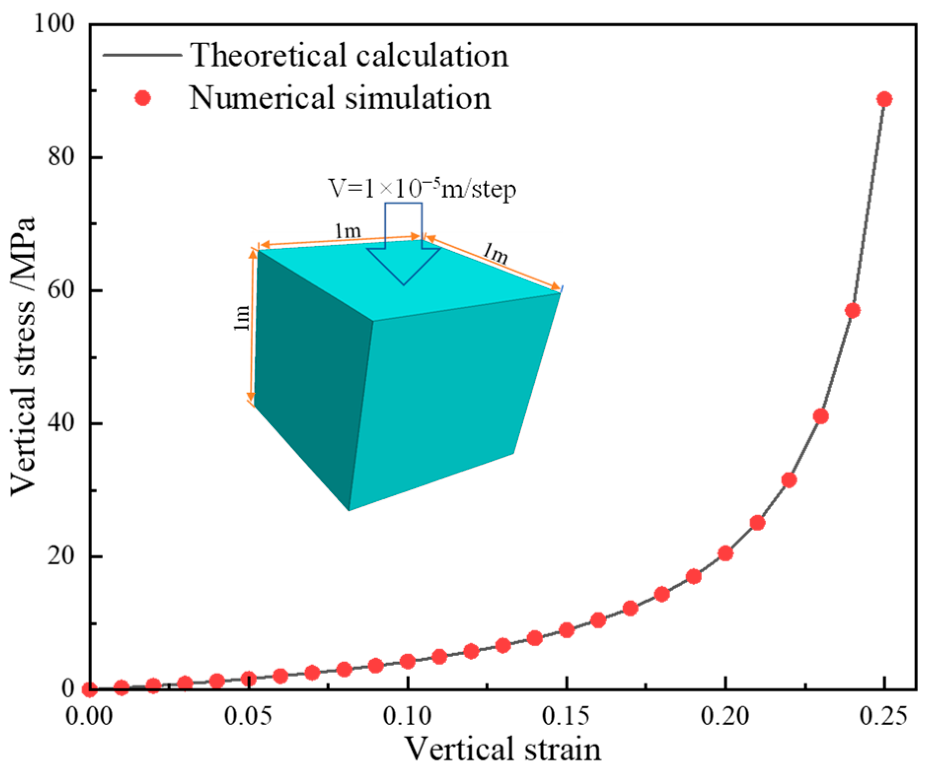
4.1. Numerical Simulation Modelling

4.1.1. Determination of the Parameters of the Goaf Collapse Zone

The process of goaf gangue compaction needs to be considered when using numerical simulation, for which the double-yield model is widely used [32,33,34,35]. If the model is applied to the numerical simulation of the 2109 working face of Qingwa Coal Mine, the parameters of the model need to be determined according to the actual engineering situation. The goaf material should conform to the stress–strain relationship of the broken rock mass derived by Salamon [36,37,38,39]:
σ z = E 0 ε z 1 ε z ε m a x
where σz is the vertical stress of the rock body in the extraction zone, MPa; E0 is the initial modulus of elasticity of the rock body, MPa; εz is the body strain under the action of vertical stress; and εmax is the maximum body strain. E0 and εmax can be calculated using the following equation:
E 0 = 10.39 σ c 1.042 b 7.7
ε m a x = b 1 b
where σc is the uniaxial compressive strength of the rock mass, MPa; b is the coefficient of rock mass fragmentation, calculated as follows:
b = 1 + c 1 m + c 2 100
where m is the mining height of the coal seam, m; c1 and c2 are the lithology coefficients of the roof [40], which can be calculated from Table 1. The calculated value of b was 1.37.
Inputting the parameters into Equation (10), the calculation yields the following:
σ z = 26.63 ε z 1 3.7 ε z
According to the above equation, the stress and strain correspondence in the process of rock mass collapse and compaction can be calculated, as shown in Table 2.
In the FLAC3D6.0 numerical simulation software, the cap pressure pc and plastic volume strain εp of the double-yield model need to be defined by the user, so that the stress–strain curves during the collapse and compaction of the rock mass can be simulated in accordance with the Salamon formula. In this formula, pc, σZ, εp, and εZ are determined using the correlation below, and for any set of σZ and εZ, the cap pressure pc and plastic volume strain εp can be calculated using the following formula [35]:
p c = 1 + 2 η 3 σ z
ε p = R R + 1 ε z
where pc is the cap pressure, MPa; η is the lateral pressure coefficient; εp is a plastic volumetric strain; R is the proportionality factor.
According to the inversion data in Table 3, a FLAC3D numerical simulation model of a cube with an edge length of 1 m was established, the velocity boundary was fixed around and at the bottom, and then a fixed velocity of 1 × 10⁻⁵ m/step was applied to the top for loading. The vertical stress of the Z = 0 plane was obtained by writing the FISH function, and then the model stress and its displacement at each time step were recorded using the history command of FLAC3D. The vertical stress–strain curve of the numerical model was then drawn. Comparing the numerically inverted curve with the theoretically calculated curve in Figure 5, it can be seen that the numerical simulation curve obtained using the cap pressure method is close to the theoretical curve. The parameters of the goaf double-yield model are shown in Table 4.

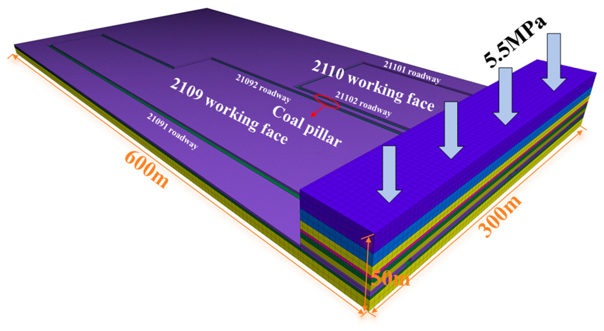
4.1.2. Numerical Simulation Model and Simulation Scheme

After the model parameters were determined, the numerical simulation was performed according to the parameters of the 2109 and 2110 working faces of Qingwa Mine, as shown in Figure 6. The dimensions of the model were 600 m × 300 m × 50 m, and a stress of 5.5 MPa was applied at the top of the model, aiming to simulate the load of the overlying rock strata layer. The surrounding area and the bottom were limited by speed as the boundary condition, and boundary coal pillars of 30 m in width were left on both sides of the working face. The numerical simulation parameters are the mechanical parameters in Table 5.
The process of the numerical simulation scheme was as follows: First, a numerical simulation model was established, parameters were assigned to each layer, and the balance was calculated. Then, the 21091 roadway was excavated, followed by the excavation of the 21092 and 21102 roadways at the same time while retaining different coal pillar widths (5~10 m). Next, a FISH command was generated to excavate the 2109 working face and fill the goaf, and after the mining of the 2109 working face, the 21101 roadway of the 2110 working face was excavated. Then, the cyclic mining and filling of 2110 working face was carried out, and the evolution of vertical stresses and plastic zones under full dynamic pressure was analyzed under different coal pillar widths during double-roadway excavation, the first mining (2109 working face), and secondary mining (2110 working face).

4.2. Research on the Bearing Characteristics of Coal Pillars Under the Influence of Full Dynamic Pressure

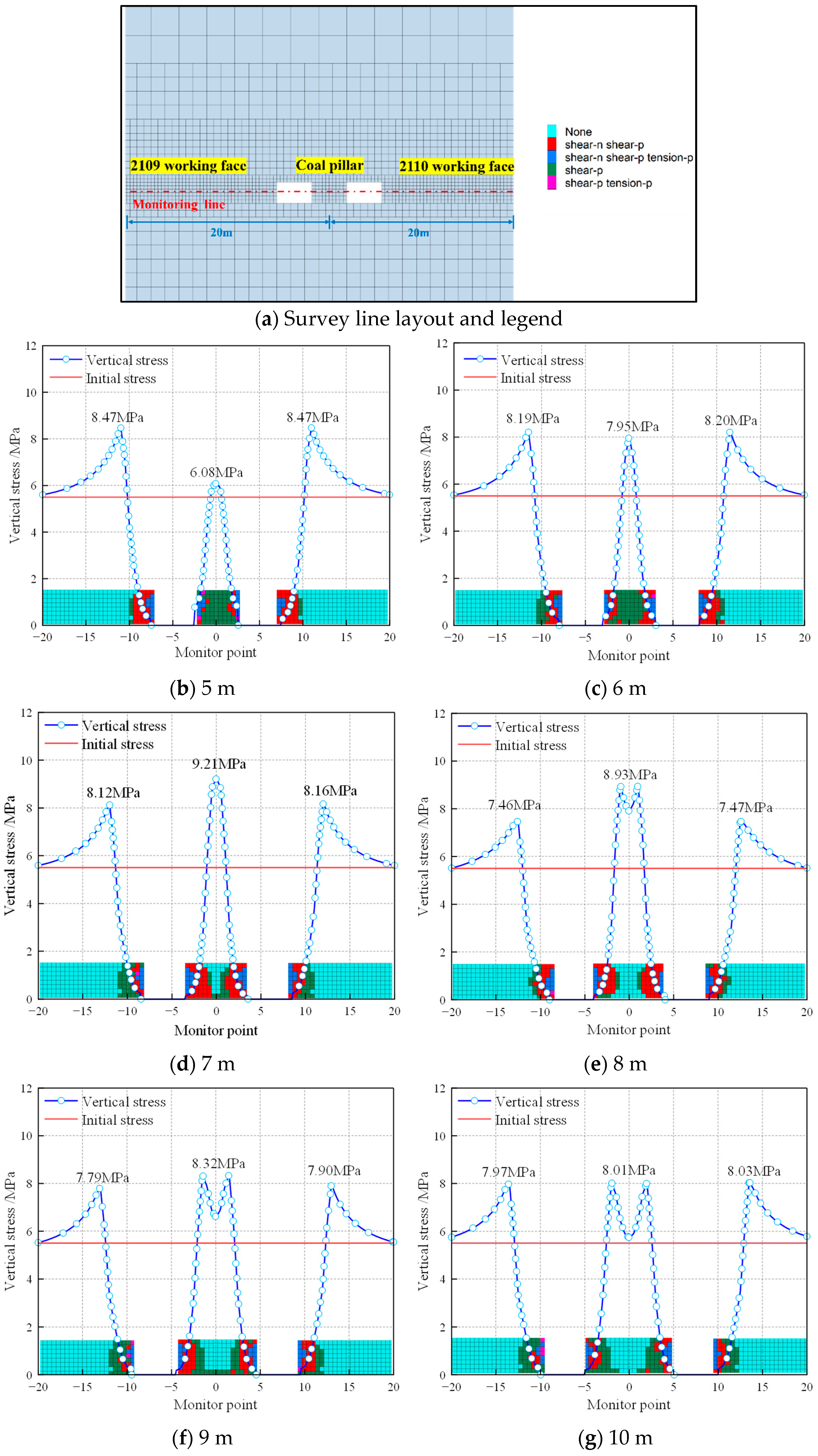
4.2.1. Bearing Characteristics of Different Coal Pillar Widths During Double-Roadway Excavation

To clarify the bearing characteristics of different coal pillar widths during double-roadway excavation using the FISH language roadway, the 21091, 21092, and 21102 roadways were excavated with each excavation step set at 5 m after calculating the equilibrium. Then, the next excavation cycle was carried out to determine the distribution of the coal pillar stress, the surrounding rock stress in the roadway, and the plastic zone during double-roadway excavation; the results are shown in Figure 7.
Taking the center of the coal pillar as the origin, vertical stresses were measured at grid points located +20 m ahead and −20 m behind the coal pillar. The results indicate the following:
(1)
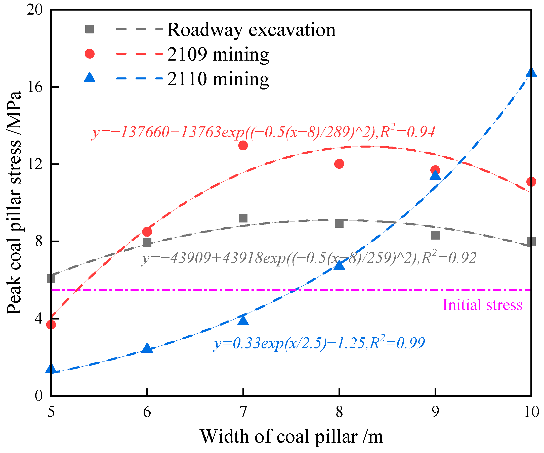
When the coal pillar width was 5 m, the vertical stress within the coal pillar reached 6.08 MPa, slightly exceeding the initial stress of 5.5 MPa (1.11 times). At this point, the coal pillar reached its yield limit, with a predominance of grids in the plastic failure zone and fewer grids in the undamaged elastic region.
(2)
When the coal pillar width increased to 6 m, the vertical stress increased to 7.95 MPa, significantly higher than the initial stress (1.45 times). The bearing capacity of the coal pillar also increased to 1.45 MPa.
(3)
With a coal pillar width of 7 m, the peak stress increased to 9.21 MPa (1.67 times the initial stress). The number of grids in the elastic zone further increased, while the plastic zone remained intact, forming an elastic core area with a width of 1 m.
(4)
For a coal pillar height of 8 m, the peak stress exhibited a bimodal distribution, reaching 8.93 MPa (1.62 times the initial stress). The width of the elastic core area expanded to 2 m, with a significant increase in the number of grids in the elastic zone and a marked reduction in the number of grids in the plastic zone.
(5)
When the coal pillar widths were 9 m and 10 m, the peak stress remained bimodal, with values of 8.32 MPa (1.51 times the initial stress) and 8.01 MPa (1.46 times the initial stress). Compared to the 8 m coal pillar, the peak stress and stress concentration coefficient decreased substantially, while the width of the elastic core area increased to 3 m and 4 m. This led to a significant increase in the number of grids in the elastic zone, enhancing the bearing capacity and stability of the coal pillar.
When the coal pillar width was relatively narrow (5–7 m), the corresponding bearing capacity increased gradually. During this phase, stress superposition within the coal pillar was more pronounced, resulting in a single-peak distribution of vertical stress. Consequently, the peak stress within the coal pillar increased progressively. Although the coal pillar exhibited some bearing capacity, the plastic zone either penetrated entirely or posed a risk of penetration. In such cases, external mining disturbances can easily cause the yielding and destruction of the coal pillar, leading to relatively low peak stress values. Conversely, when the coal pillar width was wider (8–10 m), stress superposition weakened, and the peak stress within the coal pillar exhibited a double-peak distribution. As a result, the peak stress showed a gradual decreasing trend.

4.2.2. Bearing Characteristics of Different Coal Pillar Widths During the Mining of the 2109 Working Face

In order to study the bearing characteristics of different coal pillar widths during the first mining, the step distance of each mining was 10 m, and the cycle command was written in the FISH language for mining, and the parameters of the goaf were the double-yield parameters shown in Table 4.
To analyze the bearing characteristics of the coal pillar during the first mining of the 2109 working face, the simulation was terminated when the mining distance was equal to the width of the working face. The measurement line arrangement, as depicted in Figure 8a, was established with the coal pillar’s center as the origin. This setup facilitated the acquisition of vertical stresses within the coal pillar grid spanning from −5 m to +25 m. The findings are as follows:
(1)
For a 5 m coal pillar, the vertical stress measured 3.69 MPa, which was below the initial stress (0.67 times). This indicates the occurrence of yield failure in the coal pillar, predominantly characterized by a plastic failure network structure, with minimal presence in the elastic zone.
(2)
In the 6 m coal pillar, the peak stress reached 8.5 MPa, exceeding the initial stress (1.55 times). This suggests that the coal pillar retained some bearing capacity, with a minor elastic component present and incomplete plastic failure development.
(3)
When the coal pillar measured 7 m, the peak stress increased to 12.97 MPa (2.36 times the initial stress). While the bearing capacity became more pronounced, the coal pillar remained unstable due to extensive plastic failure grids and plastic infiltration.
(4)
For the 8 m coal pillar, the stress curve exhibited an approximate double-peak pattern, with a peak stress of 12.02 MPa (2.19 times the initial stress). The elastic core width measured merely 1 m, showing increased width and grid count in the elastic zone compared to the 7 m pillar, alongside a significant reduction in plastic zone grids.
(5)
In the 9 m and 10 m coal pillars, the peak stress demonstrated a distinct bimodal pattern, measuring 11.69 MPa (2.13 times the initial stress) and 11.09 MPa (2.02 times the initial stress), which were reduced compared with the 8 m coal pillar. By contrast, the width of the elastic core area and the number of grids in the elastic zone significantly increased, and the bearing capacity and stability were improved.
During the first mining, the change in the stress peak value was relatively small, and the stress value did not significantly change. The peak value of the stress in the coal pillar was the same as that in the mining period, which increased rapidly to the maximum with the increase in the width of the coal pillar, and then gradually decreased. At this time, the bearing capacity and failure of the coal pillar were the same in the first mining period.

4.2.3. Bearing Characteristics of Different Coal Pillar Widths During the Mining of the 2110 Working Face
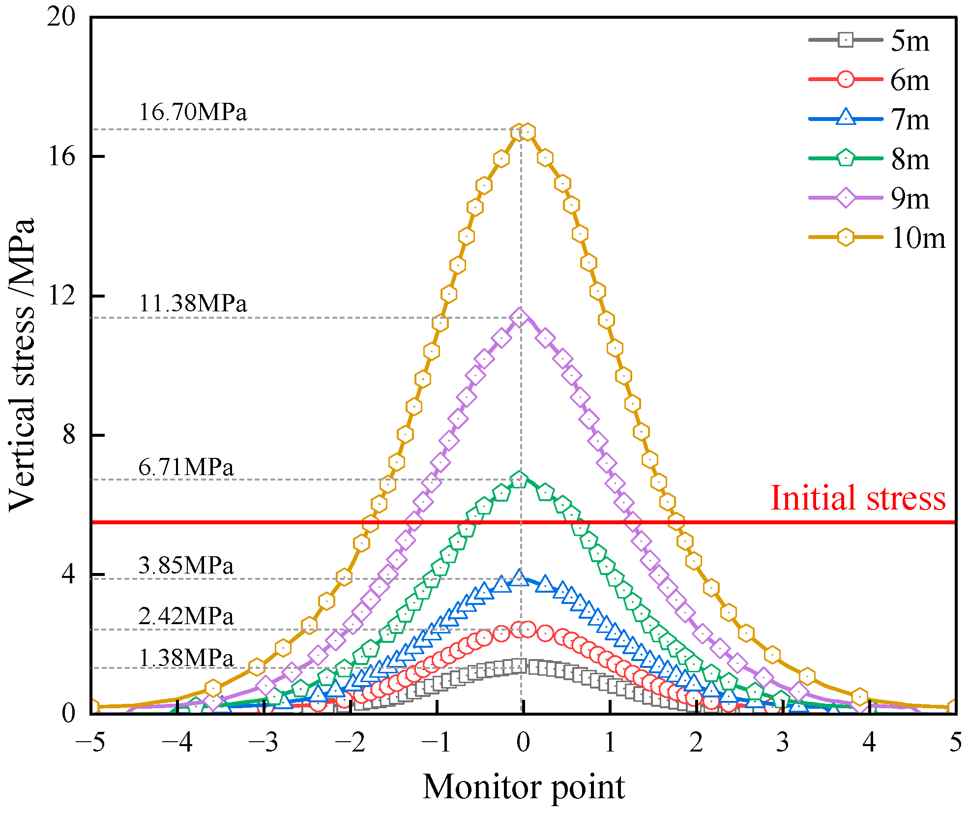
To study the bearing characteristics of different coal pillar widths during the mining of the 2110 working face, for which the same mining scheme was used as the first mining, the bearing characteristics of different coal pillar widths were analyzed during the secondary mining. Both sides of the coal pillar after the second mining were goaf areas, and the measurement line of the coal pillar was arranged. The results are shown in Figure 9 and Figure 10.
(1)
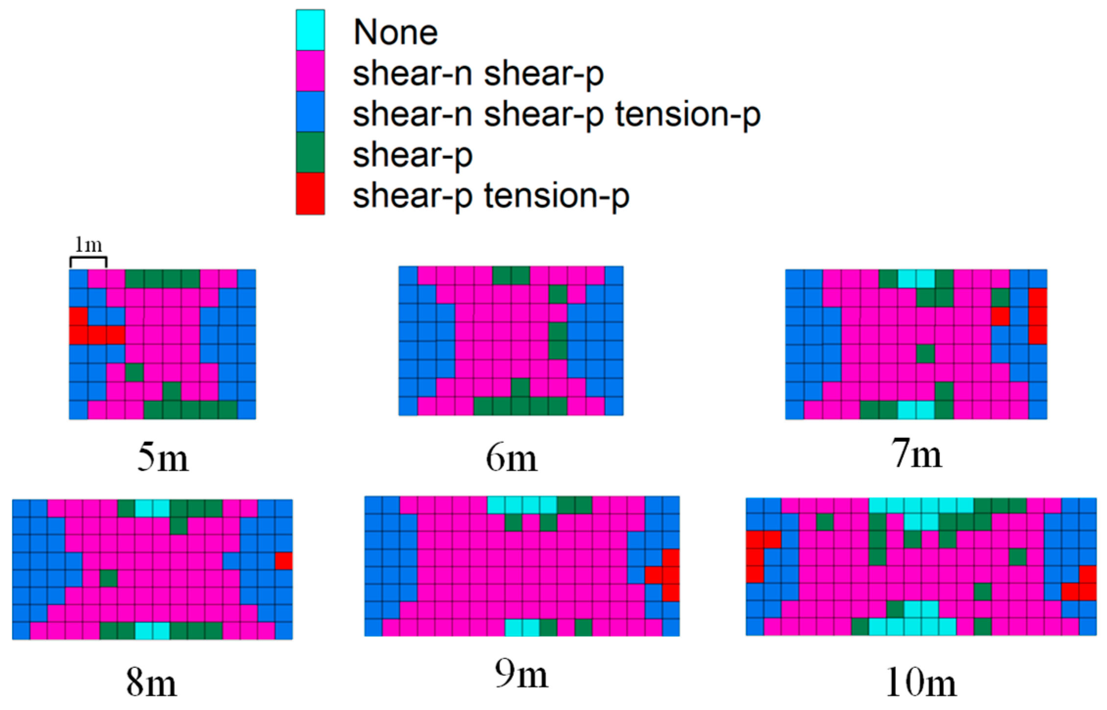
The vertical stress curves of coal pillars with varying widths during secondary mining exhibited unimodal distributions that were symmetrical about the coal pillar’s centerline. As the width of the coal pillar increased, both the vertical stress curve and its peak value demonstrated corresponding growth. The maximum vertical stress for 5 m to 7 m coal pillars remained significantly below the initial stress. In contrast, the 8 m coal pillar showed a maximum vertical stress slightly exceeding the initial stress, while the 9 m and 10 m coal pillars exhibited maximum vertical stresses that were 2.07 and 3.04 times the initial stress.
(2)
The analysis of the plastic zone contour diagram reveals that the lattice structures of both 5 m and 6 m coal pillars underwent plastic failure. When the coal pillar width exceeded 7 m, the majority of the lattice structures experienced plastic failure, with only a limited number of elastic lattices remaining. The plastic zones beneath each coal pillar width were fully penetrated, leaving no elastic core area. However, as the coal pillar width increased, there was a gradual augmentation in the number of lattice structures within the elastic zone.

4.3. Analysis of Coal Pillar Stability Under the Influence of Full Dynamic Pressure

According to the numerical simulation results of full dynamic pressure during roadway excavation, first mining, and secondary mining, the peak stress curve of the coal pillar under the influence of full dynamic pressure was drawn, which is shown in Figure 11.
The peak stress of coal pillars across various mining stages was systematically analyzed through curve fitting. The fitting curves, as illustrated in the equation below, demonstrate that the GaussAmp function was employed for nonlinear fitting during roadway excavation and primary mining phases, while the exponential function was utilized for the secondary mining period. The correlation coefficients of 0.92, 0.94, and 0.99, respectively, indicate that the fitted curves accurately represent the data trends.
As depicted in Figure 11, the analysis reveals that, during roadway excavation and first mining, the peak stress of coal pillars exhibited a gradual increase when the width was less than 8 m, followed by a gradual decrease when exceeding 8 m, establishing 8 m as the critical threshold for peak stress transition. During the second mining, the peak stress of 5–7 m coal pillars fell below the initial stress level, indicating the structural failure and loss of load-bearing capacity. Consequently, coal pillars of 8 m and above maintained residual bearing capacity, as substantiated by the experimental findings.
The area and proportion of cross-sectional elastic zones in the roadway during the first and second mining were determined based on the cross-section of the coal pillar, and the area and proportion of elastic zones in the coal pillar under the influence of full dynamic pressure are shown in Figure 12.
With the progressive increase in coal pillar width, a corresponding expansion in both the grid and the proportional extent of the elastic zone was observed across the roadway tunneling, first mining, and second mining stages. During the initial mining phase, the grid proportion of the elastic zone in the 7 m and 8 m coal pillars exhibited the most substantial reductions, decreasing by 13.39% and 14.07%. In comparison to the first mining stage, the secondary mining phase demonstrated a marked reduction in the elastic zone across all wider coal pillars. Notably, the elastic zone completely disappeared in the 5 m and 6 m coal pillars, while the area and proportion of the elastic zone in pillars of 7 m and above in width were significantly diminished.
This phenomenon was substantiated by both the peak stress curve and the proportional analysis of the elastic zone:
(1)
Following the primary mining operation, with the exception of the 5 m coal pillar, which exhibited a stress reduction of 2.39 MPa, all other width categories demonstrated stress increments of 0.55 MPa, 3.76 MPa, 3.09 MPa, 3.37 MPa, and 3.08 MPa. Notably, the stress increase in coal pillars of 7 m and above in width showed minimal variation. Concurrently, the elastic zone and its proportional extent across different width categories experienced measurable reductions. These observations indicate that while coal pillars of 6 m and above maintained load-bearing capacity under first mining stress conditions, the internal plastic zone underwent progressive development. This suggests a dual state of maintained structural integrity coupled with internal plastic deformation.
(2)
Subsequent to the second mining phase, comparative analysis revealed stress reductions of 2.31 MPa, 6.08 MPa, 9.12 MPa, 5.31 MPa, and 0.31 MPa in 5 m to 9 m coal pillars, respectively, in contrast to a 5.61 MPa increase in the 10 m pillar. The vertical stress in 5 m–7 m coal pillars fell below initial stress levels, indicating structural failure and complete loss of bearing capacity, as evidenced by the absence or minimal presence of elastic zones. Conversely, the 8 m and 9 m coal pillars, while maintaining stress levels above initial values, demonstrated reduced peak stress, signifying their transition into the plastic yield stage. Although these pillars retained residual bearing capacity, their elastic zones remained substantially diminished.
For the NCPDRE, the coal pillar, in addition to the bearing capacity, should also avoid plastic zone penetration after the first mining operation, in order to isolate the gas in the goaf area. The plastic zone cloud map generated after the first mining indicated that the plastic zone of the 7 m coal pillar was penetrated, and there was still a 1 m elasticity in the internal core area of the 8 m coal pillar; after comprehensive consideration, it was determined that the optimal width of the NCPDRE was 8 m.

5. Field Industrial Experiment

In order to clarify the impact of full dynamic pressure on the mining of the 21092 and 21102 roadways, considering mineral pressure characteristics, in each of the two roadways, surface displacement monitoring stations were set up to observe the roadway surface displacement. A station cloth was set using the cross-point method, within 50 m of the monitoring station. Observations were made once a day, 2~3 times a week; see Figure 13.
It can be seen from Figure 14a that during the first mining period of the 21092 roadway, compared with the roadway excavation period, the roof subsidence increased by 83%, the floor displacement increased by 128%, the right displacement increased by 33%, and the left displacement increased by 61%. For the 21102 roadway, the roof subsidence increased by 80%, the floor displacement increased by 79%, the right displacement increased by 43%, and the left displacement increased by 15%. The impact on the displacement of the roadway roof and floor was the greatest during the first mining period. The second mining was performed on the solid coal side, which had little impact on the displacement of the coal pillar side. It can be seen from Figure 14b that during the second mining of the 21102 roadway, compared with the first mining, the roof subsidence increased by 6%, the floor displacement increased by 53%, the right displacement increased by 20%, and the left displacement increased by 27%. The impact on the roadway roof deformation during the secondary mining period was the smallest, and the impact on the roadway floor was the largest.

6. Conclusions

(1)
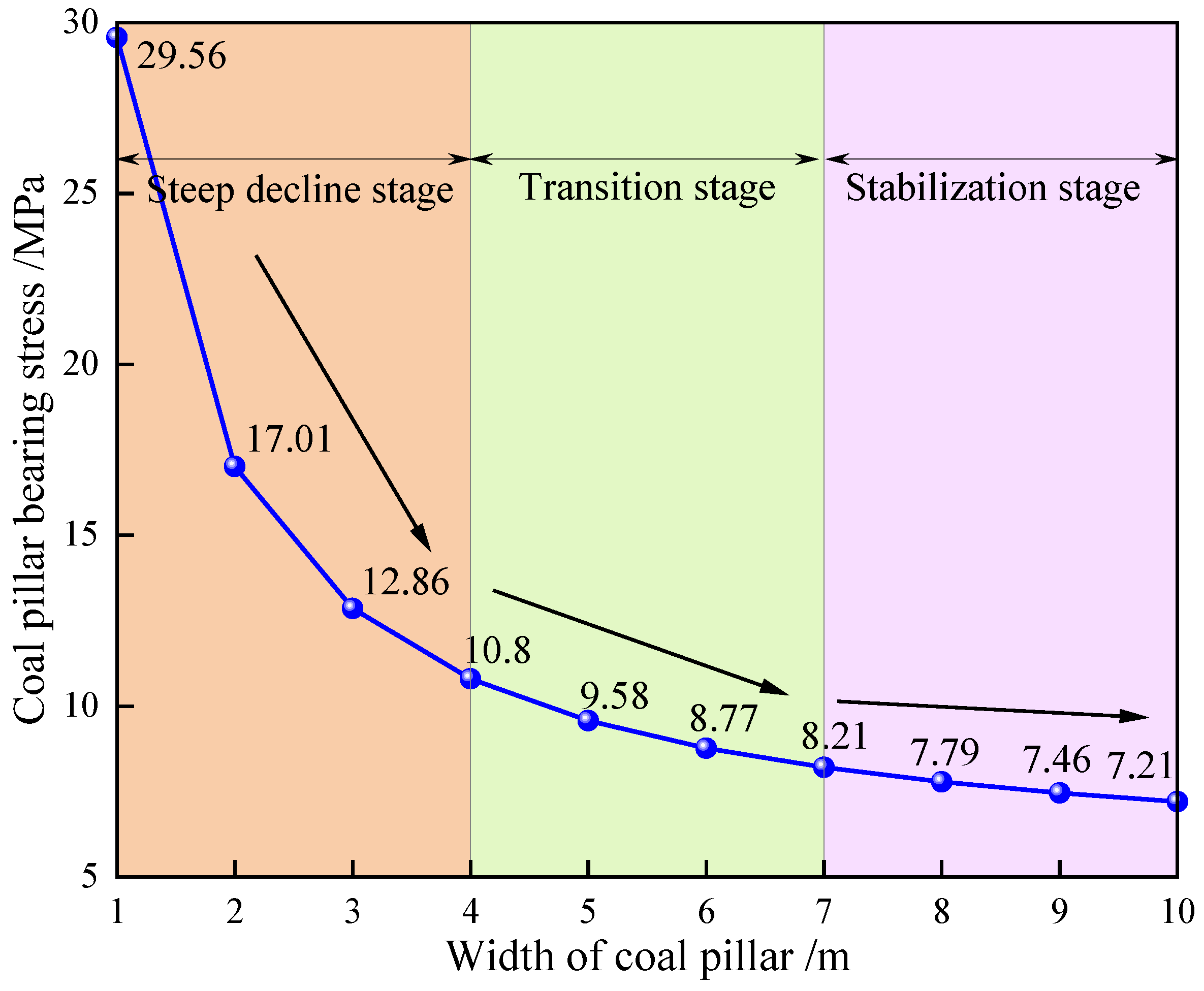
A comprehensive mechanical model of the immediate roof following upper section working face mining was developed, incorporating the derived relationship between the coal pillar bearing load and the immediate roof length. The bearing stress characteristics of coal pillars in Qingwa Coal Mine were categorized into three distinct phases: the steep decline stage (0–4 m), transition stage (4–7 m), and stabilization stage (>7 m). Coal pillars within the stabilization phase’s width range demonstrated measurable strength surplus capacity, indicating enhanced structural integrity.
(2)
Through numerical simulation analysis, the bearing characteristics of 5 m–10 m coal pillars were systematically examined across roadway excavation, first mining, and second mining. The investigation revealed that, for 5 m–7 m pillars, significant internal stress superposition occurred, manifesting as a single-hump distribution pattern with progressively increasing peak stress. Conversely, 8 m–10 m pillars exhibited reduced internal stress superposition, characterized by a double-hump distribution pattern with gradually decreasing peak stress. During the first mining operation, the vertical stress distribution within the pillars transitioned from single-hump to double-hump configurations as the width increased. Second mining analysis demonstrated complete plastic failure in the 5 m and 6 m coal pillar meshes, while the 7 m and wider pillars showed extensive plastic damage with fully penetrated plastic zones across all width categories.
(3)
Under the influence of full dynamic pressure, the 5–7 m coal pillars yielded and were destroyed, whereas the 8 m and above coal pillars had certain residual bearing capacity, compared with the first mining. After the second mining, the elastic zone grid of each width of the coal pillar was sharply reduced. The 5 m and 6 m coal pillars were no longer in the elastic grid, whereas the elastic zone grid area and proportion of the 7 m and above coal pillars were very low. In order to avoid plastic zone penetration after the first mining, it was determined that the optimal width of NCPDRE was 8 m.
(4)
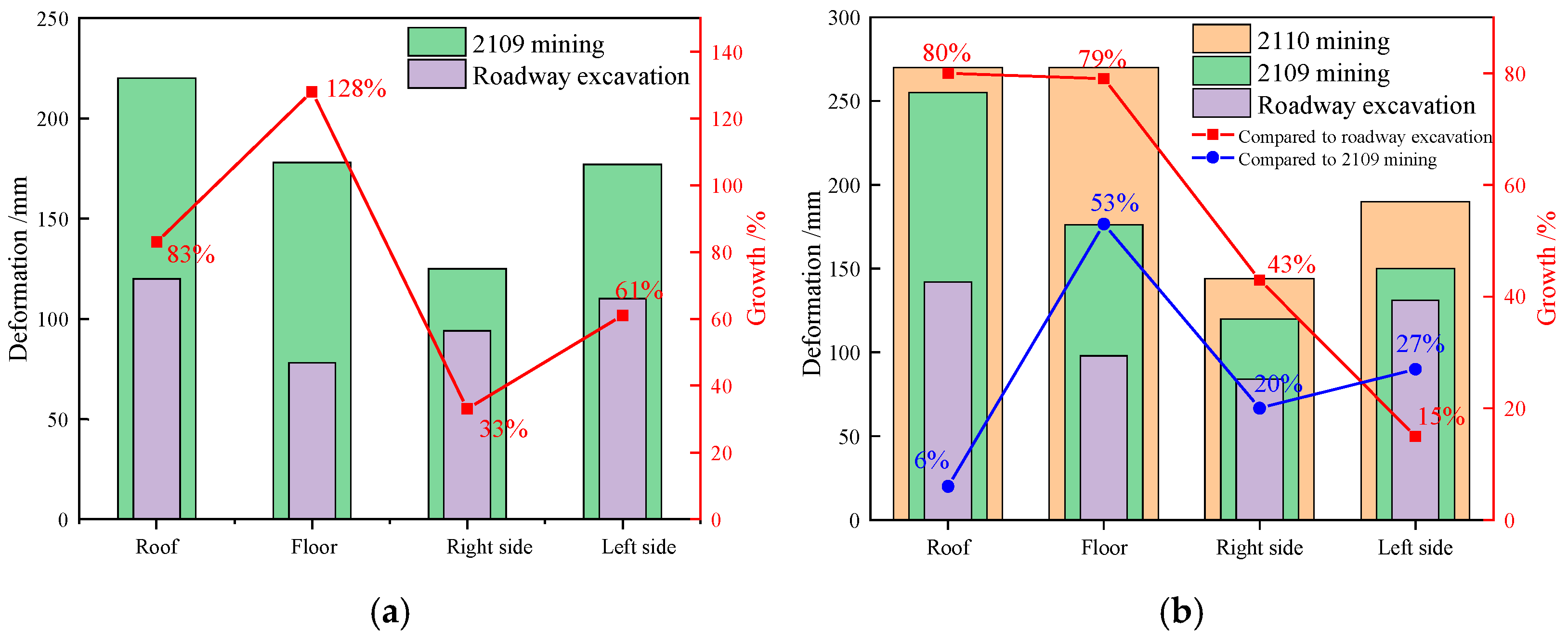
The observation and analysis of the displacement of the roadway surface under the influence of full dynamic pressure showed that the first mining had a greater influence on the displacement of the roof and floor of the roadway, followed by the solid coal side, whereas the displacement of the coal pillar side was smaller; the second mining had a greater influence on the floor, followed by the coal pillar side and the solid coal side, whereas the displacement of the roof had a smaller influence.

Author Contributions

Conceptualization, W.G.; methodology, W.G.; software, D.X., J.P., and H.Z.; validation, H.Z. and D.X.; formal analysis, S.W. and H.Z.; investigation, H.T. and D.X.; resources, W.G.; data curation, H.Z.; writing—original draft preparation, H.T. and Z.H.; writing—review and editing, H.Z. and W.G.; visualization, D.X.; supervision, W.G.; project administration, D.X.; funding acquisition, W.G. All authors have read and agreed to the published version of the manuscript.

Funding

This research was funded by the National Natural Science Foundation of China, grant number 52274103.

Institutional Review Board Statement

Not applicable.

Informed Consent Statement

Not applicable.

Data Availability Statement

The raw data supporting the conclusions of this article will be made available by the authors upon request.

Conflicts of Interest

The authors declare no conflicts of interest.

References

  1. Ge, S.; Liu, S.; Liu, J.; Wang, B.; An, X.; Xiang, L. Effectiveness of secure supply and carbon reduction in the coal sector for strengthening the energy power of China. Strateg. Study CAE 2024, 26, 40–51. [Google Scholar]
  2. Wang, S. Thoughts about the main energy status of coal and green mining in China. China Coal 2020, 46, 11–16. [Google Scholar]
  3. Ge, S.; Fan, J.; Liu, S.; Song, M.; Xian, Y.; Wang, B.; Teng, T. Low carbon modern coal-based energy technology system and development strategy. J. China Coal Soc. 2024, 49, 203–223. [Google Scholar]
  4. Yuan, L. Strategic conception of carbon neutralization in coal industry. Strateg. Study CAE 2023, 25, 103–110. [Google Scholar] [CrossRef]
  5. Yu, Y.; Liang, H.; Chen, Y.; Zhao, X. Study on spatiotemporal effect and control technology of roadway driving face to mining. Coal Technol. 2018, 37, 18–21. [Google Scholar]
  6. Jia, H.; Zhang, Z.; Liu, S.; Peng, B.; Yu, H.; Shao, S.; Wang, Y. Research on dissimilation characteristics and control method of failure of surrounding rock in the roadway with repeated mining of steep and ultra-close multiple coal seam. Coal Sci. Technol. 2025, 53, 67–79. [Google Scholar]
  7. Kumar, R.; Mandal, P.K.; Ghosh, N.; Das, A.J.; Banerjee, G. Design of Stable Parallelepiped Coal Pillars Considering Geotechnical Uncertainties. Rock Mech. Rock Eng. 2023, 56, 6581–6602. [Google Scholar] [CrossRef]
  8. Zhang, Z.; Li, Z.; Xu, G.; Gao, X.; Liu, Q.; Li, Z.; Liu, J. Lateral abutment pressure distribution and evolution in wide pillars under the first mining effect. Int. J. Min. Sci. Technol. 2023, 33, 309–322. [Google Scholar] [CrossRef]
  9. Tai, Y.; Yu, B.; Xia, B.; Li, Z.; Xia, H. Research on stress release for the gob-side roadway using the roof-cutting technology with a chainsaw arm. R. Soc. Open Sci. 2020, 7, 191663. [Google Scholar] [CrossRef]
  10. Xia, Z.; Yao, Q.; Xu, Q.; Ma, J.; Liu, Z. Numerical-modeling-based assessment of the impact of two-end-type cable support on failure characteristics of yield pillars. Eng. Fail. Anal. 2021, 128, 105619. [Google Scholar] [CrossRef]
  11. Wang, M.; Wang, W.; Xu, Y.; Xie, G.; Qin, J.; Liu, H.; Wei, S.; Xu, Q. Study on the new layout pattern about the gob-side entry under dynamic pressure and its surrounding rock stability control. Energy Sci. Eng. 2024, 12, 1389–1410. [Google Scholar] [CrossRef]
  12. Bai, W.; Xu, Q.; Li, Y.; Li, T. Reasonable width of coal pillar between roadways during double lane driving with large mining height. Saf. Coal Mines 2019, 50, 212–215. [Google Scholar]
  13. Huang, W.; Liu, S.; Gao, M.; Hou, T.; Wang, X.; Zhao, T.; Sui, L.; Xie, Z. Improvement of Reinforcement Performance and Engineering Application of Small Coal Pillars Arranged in Double Roadways. Sustainability 2023, 15, 292. [Google Scholar] [CrossRef]
  14. He, Y.; Li, J. Stress Distribution and Optimum Spacing Determination of Double-Withdrawal-Channel Surrounding Rocks: A Case Study of Chinese Coal Mine. Shock Vib. 2021, 2021, 9973634. [Google Scholar] [CrossRef]
  15. Zhang, S.; Huang, F.; Wang, C.; Li, X.; Li, Q. Stability and control of surrounding rock in double lane tunneling with deep high stress. China Min. Mag. 2022, 31, 104–112. [Google Scholar]
  16. Li, C.; Xin, D.; Liu, Y.; Chen, T. A Case Study on Strong Strata Behaviors Mechanism of Mining Reserved Roadway and Its Prevention Techniques. Processes 2023, 11, 1341. [Google Scholar] [CrossRef]
  17. Qian, D.; Jiao, H.; Deng, J.; Yang, J.; Jiao, M.; Xian, G.; Yu, C.; Zhu, Y.; Liu, J.; Huang, S.; et al. Instability Mechanism, Pressure Relief, and Long Anchorage Control Countermeasures for Surrounding Rock of Strong Mining Roadway at Large Mining Height Working Face. Minerals 2023, 13, 391. [Google Scholar] [CrossRef]
  18. Liu, S.; Bai, J.; Wang, X.; Wang, G.; Wu, B.; Li, Y.; Zhao, J. Study on the Stability of Coal Pillars Under the Disturbance of Repeated Mining in a Double-Roadway Layout System. Front. Earth Sci. 2021, 9, 754747. [Google Scholar] [CrossRef]
  19. Han, B.; Zhang, C.; Zhang, C.; Wang, S. Mechanism of pressure relief for double roadway arrangement in thick coal seam. J. Taiyuan Univ. Technol. 2024, 55, 989–999. [Google Scholar]
  20. Wu, X.; Liu, H.; Li, J.; Guo, X.; Lu, K.; Wang, J. Temporal-spatial evolutionary law of plastic zone and stability control in repetitive mining roadway. J. China Coal Soc. 2020, 45, 3389–3400. [Google Scholar]
  21. Wu, X.; Wang, J.; Chen, S.; Zhang, Y.; Bu, Q. Regulation principle and stability control of plastic zone in repeated mining roadway. Rock Soil Mech. 2022, 43, 205–217. [Google Scholar]
  22. Wu, X.; Pang, Z.; Zhao, S.; Zhang, Y.; Lv, K.; Wang, S. Scale-span evolution law mechanical mechanism of surrounding rock cracks in repeated mining roadway. J. China Coal Soc. 2024, 49, 579–592. [Google Scholar]
  23. Wu, X.; Wang, J.; Guo, X.; Wang, E.; Cao, J. Morphological characteristics and quantitative discriminant method of superimposed plastic zone expansion of surrounding rock of repeated mining roadway. J. China Univ. Min. Technol. 2024, 53, 46–58+105. [Google Scholar]
  24. Liu, J.; Lv, K.; Wu, Z.; Zhao, B.; Wang, P.; Sun, X.; Cao, J. Study on failure mechanism and control of surrounding rock of secondary mining roadway in thick and hard roof coal seam. Met. Mine 2024, 12, 77–87. [Google Scholar]
  25. Fan, L.; Chang, J.; Wang, W.; Yuan, C.; Wu, H.; Qi, C. Research on the influencing factors and evolution law of structural stability of surrounding rock of mining roadway. J. Min. Saf. Eng. 2025, 42, 589–600. [Google Scholar]
  26. Skrzypkowski, K. Comparative Analysis of the Mining Cribs Models Filled with Gangue. Energies 2020, 13, 5290. [Google Scholar] [CrossRef]
  27. Tahmasebinia, F.; Yang, A.; Feghali, P.; Skrzypkowski, K. Structural Evaluation of Cable Bolts under Static Loading. Appl. Sci. 2023, 13, 1326. [Google Scholar] [CrossRef]
  28. Li, G.; Wang, X.; Bai, J.; Wu, B.; Wu, W. Research on the failure mechanism and control technology of surrounding rock in gob-side entry driving under unstable overlying strata. Eng. Fail. Anal. 2022, 138, 106361. [Google Scholar] [CrossRef]
  29. He, M.; Zhu, G.; Guo, Z. Longwall mining “cutting cantilever beam theory” and 110 mining method in China—The third mining science innovation. J. Rock Mech. Geotech. Eng. 2015, 7, 483–492. [Google Scholar] [CrossRef]
  30. Wang, J.; Liu, P.; Jiang, J.; Sun, Z. Y-shaped ventilation air leakage law of working face of gob-side entry retaining by cutting roof to release pressure. J. Min. Saf. Eng. 2021, 38, 625–633. [Google Scholar]
  31. Liu, X.; Hua, X.; Yang, P.; Huang, Z. A study of the mechanical structure of the direct roof during the whole process of non-pillar gob-side entry retaining by roof cutting. Energy Explor. Exploit. 2020, 38, 1706–1724. [Google Scholar] [CrossRef]
  32. Guo, Y.; Lu, C.; He, Z.; Song, J. Numerical and Field Investigations of Tremors Induced by Thick-Hard Strata Fracture. Appl. Sci. 2022, 12, 11151. [Google Scholar] [CrossRef]
  33. Wang, M.; Xu, Y.; Xu, Q.; Shan, C.; Li, Z.; Nan, H.; Li, Y.; Liu, H.; Chu, T. Stability control of overburden and coal pillars in the gob-side entry under dynamic pressure. Int. J. Rock Mech. Min. Sci. 2023, 170, 105490. [Google Scholar] [CrossRef]
  34. Xia, B.; Gong, T.; Yu, B.; Zhou, L. Numerical simulation method for stope underground pressure in whole process of longwall mining. J. China Coal Soc. 2017, 42, 2235–2244. [Google Scholar]
  35. Shan, C.; Qi, S.; Xie, G.; Qin, J.; Li, Y.; Huang, P.; Zhang, Q.; Ren, G. Study on Multi-scale strength and Control of Coal Pillar in Gob Side Entry of Fully Mechanized Top Coal Caving Face in “Double Hard’ Seam. Coal Technol. 2023, 42, 63–68. [Google Scholar]
  36. Sabapathy, R.; Mandal, P.K.; Paul, P.S.; Das, A.J. Evaluation of potentiality of coal bump hazard in underground coal mines through numerical modelling and binary logistic regression approach with field validation. Bull. Eng. Geol. Environ. 2025, 84, 333. [Google Scholar] [CrossRef]
  37. Matinpour, F.; Majdi, A. Determining the abutment angle in longwall coal mining using NLMR, GEP and GEO techniques. Earth Sci. Inform. 2025, 18, 358. [Google Scholar] [CrossRef]
  38. Salamon, M.D.G. Mechanism of caving in longwall coal mining. In Rock Mechanics Contributions and Challenges, Proceedings of the 31st U.S. Symposium, Golden, CO, USA, 18–20 June 1990; CRC Press: Boca Raton, FL, USA, 2020. [Google Scholar]
  39. Bai, M.; Kendorski, F.S.; Van Roosendaal, D.J. Chinese and North American high-extraction underground coal mining strata behavior and water protection experience and guidelines. In Proceedings of the Conference on Ground Control in Mining, Morgantown, WV, USA, 1–3 August 1995. [Google Scholar]
  40. Zhang, Y. Research and Application of Reserved Narrow Coal Pillar Roof Cutting and Pressure Relief Technology in Qingyun Coal Industry. Shandong Coal Sci. Technol. 2023, 41, 27–31. [Google Scholar]
Figure 1. Geographic location of Qingwa Mine: (a) location of Qingwa Mine in China; (b) location of Qingwa Mine in Linfen City; (c) the histogram of the 2109 working face; (d) the 2109 and 2110 working face layout.
Applsci 15 07148 g001
Figure 2. NCPDRE layout: (a) narrow coal pillar double-lane excavation layout; (b) A-A section (1—this section’s return-air roadway; 2—this section’s air-inlet roadway; 3—coal pillar; 4—next section’s return-air roadway).
Applsci 15 07148 g002
Figure 3. The mechanical model of the immediate roof after upper section mining.
Applsci 15 07148 g003
Figure 4. Coal pillar width and its bearing stress curve.
Applsci 15 07148 g004
Figure 5. Theoretical calculations and numerical inversion curves.
Applsci 15 07148 g005
Figure 6. Numerical calculation model.
Applsci 15 07148 g006
Figure 7. Distribution of stress and plastic zone during the roadway excavation.
Applsci 15 07148 g007
Figure 8. Distribution of stress and plastic zone during the 2109 working face mining.
Applsci 15 07148 g008aApplsci 15 07148 g008b
Figure 9. Vertical stress curves of different coal pillar widths in secondary mining.
Applsci 15 07148 g009
Figure 10. Contour of the plastic zone with different coal pillar widths under secondary mining.
Applsci 15 07148 g010
Figure 11. The peak stress curve of the coal pillar under the influence of full dynamic pressure.
Applsci 15 07148 g011
Figure 12. The area of the elastic zone of the coal pillar under the influence of full dynamic pressure and its percentage.
Applsci 15 07148 g012
Figure 13. Schematic diagram of station layout.
Applsci 15 07148 g013
Figure 14. Maximum surface displacement and its amplitude in lanes 21092 and 21102: (a) maximum surface displacement and its increase in the 21092 roadway; (b) maximum surface displacement and its increase in the 21102 roadway.
Applsci 15 07148 g014
Table 1. Height coefficients for collapsed areas.
Immediate Roof LithologyCompressive Strength/MPac1c2
hard>402.116
medium hard20–404.719
weak<206.232
Table 2. Stress and strain correspondence during rock mass collapse and compaction.
Vertical strain εZ00.050.10.150.20.25
Vertical stress σZ/MPa01.634.238.9820.4888.77
Table 3. Cap pressure inversion comparison.
Vertical strain εZ00.050.10.150.20.25
Volume strain εp00.03750.0750.11250.150.1875
cap pressure pc/MPa00.541.412.996.8329.59
Table 4. Parameters of the double-yield model.
Bulk/GPaShear/GPaDensity/(kg × m−3)Internal Friction Angle/°
5.564.7180020
Table 5. Numerical simulation parameters.
LayerBulk/GPaShear/GPaPoisson’s RatioInternal Friction Angle fCohesion C/MPa
Siltstone2.011.760.2738.050.71
2#Coal0.210.220.2118.490.25
Mudstone0.510.540.2123.640.34
Fine sandstone3.333.020.2646.741.29
Sandstone2.422.800.1743.451.10
Disclaimer/Publisher’s Note: The statements, opinions and data contained in all publications are solely those of the individual author(s) and contributor(s) and not of MDPI and/or the editor(s). MDPI and/or the editor(s) disclaim responsibility for any injury to people or property resulting from any ideas, methods, instructions or products referred to in the content.

