1. Introduction
Despite the expanding clinical applications of clear aligner (CA) therapy, structural limitations in effectively achieving bodily tooth movement still remain [
1,
2]. These limitations are primarily attributed to the low stiffness of the aligner material and the nature of the force system, which is typically applied near the center of the crown. Consequently, root movement is often insufficient, leading to increased tipping, commonly referred to as the “Roller-Coaster Effect” [
3,
4]. This biomechanical shortcoming is particularly problematic in complex cases that require precise tooth control, such as during extraction space closure.
The literature describes various strategies to address biomechanical limitations of CA therapies. One approach involves increasing aligner rigidity by modifying physical properties, including the development of multilayer materials with enhanced stiffness, the incorporation of reinforcing fibers, and the optimization of thermoplastic polymer compositions. For instance, studies have investigated polyethylene terephthalate glycol (PETG) and thermoplastic polyurethane (TPU) materials with varying elastic moduli to achieve optimal force delivery characteristics. Although these material modifications can reduce appliance deformation and promote more precise tooth movement, such changes may affect overall treatment dynamics, patient comfort, and cost-effectiveness, necessitating further research and cautious clinical implementation [
5]. Other approaches involve the use of auxiliary appliances such as attachments, power ridges, intraoral elastics, and temporary anchorage devices (TADs) [
6,
7,
8,
9,
10]. Although these adjuncts can enhance the magnitude and direction of orthodontic forces, they have several drawbacks, including difficulty in appliance removal, increased patient discomfort and pain, and unintended biomechanical effects on the adjacent non-attached teeth [
11,
12].
Despite these improvements, the predictability and efficiency of tooth movement with CAs remains suboptimal. Therefore, continued efforts toward the biomechanical optimization of aligner design in conjunction with improved treatment protocols are essential for improving clinical outcomes [
13]. Recent studies have demonstrated that specific structural design elements of CAs play critical roles in determining the direction and nature of tooth movement. These elements include aligner thickness variations that affect force magnitude and distribution, trimline design and gingival extension patterns that influence force application points, attachment configurations that enhance rotational and translational control, power ridges that create localized stress concentrations for targeted movements, and extraction space modifications such as pontic designs and structural reinforcements that affect force transmission across edentulous regions [
3,
4,
13,
14]. In line with this research trend, an increasing number of investigations have focused on analyzing how different aligner designs influence tooth movement patterns, particularly within edentulous spaces. In a study comparing non-pontic, semi-pontic (half the anatomical pontic length), and anatomic pontic designs for the anterior movement of mandibular second molars, the semi-pontic design demonstrated the highest root-to-crown movement ratio and exerted the least extrusion force, thereby facilitating the most effective bodily movement [
15]. Similarly, in a study examining the effects of non-pontic, full-pontic, half-pontic (half-width), and beam designs on the premolar extraction space during posterior canine movement, the beam design initially produced the greatest displacement. However, over time the beam design also resulted in the lowest overall displacement and inclination, confirming its superiority in controlling bodily movement [
16]. Furthermore, a study investigating the impact of CA vertical height—ranging from −4 mm to +4 mm—in the extraction space region found that canine tipping could be effectively reduced depending on the vertical design of the aligner in this area [
17,
18].
Although previous studies have investigated the influence of the design type and vertical height of CAs in the extraction space on tooth movement patterns, the specific impact of the buccolingual width of the extraction space on biomechanical characteristics of tooth movement remains insufficiently explored. From a biomechanical perspective, the buccolingual dimension of structural elements within extraction spaces directly influences force distribution and moment-to-force ratios applied to adjacent teeth. Insufficient width may result in inadequate force transmission, while excessive width could generate undesirable force magnitudes exceeding optimal biological limits. Buccolingual beam width variations become particularly relevant in patients where inadequate space closure frequently occurs due to insufficient aligner rigidity in the extraction region.
Therefore, this study aimed to evaluate the biomechanical effects of CAs with varying buccolingual beam widths on the posterior movement of the canine in the maxillary first premolar extraction site. Specifically, CAs were designed with beam widths of 0 (edentulous), 1, 2, and 3 mm within the extraction space. Using the finite element method (FEM), this study comprehensively assessed the displacement patterns of the canine, degree of tipping and rotation, deformation patterns of the aligner, and magnitudes of the generated forces and moments.
2. Materials and Methods
Finite element modeling is a computational technique that divides complex geometric structures into smaller, interconnected elements to analyze mechanical behavior under applied forces. In orthodontic applications, this method enables prediction of stress distribution, deformation patterns, and tooth movement by solving mathematical equations that describe the mechanical properties of dental tissues and appliances. The simulation process involves creating a three-dimensional digital model, assigning material properties to each component, applying boundary conditions and forces, and calculating the resulting displacements and stresses throughout the structure.
All finite element analyses in this study were performed using ANSYS 2024R software (ANSYS Inc., Canonsburg, PA, USA). The initial geometric data were obtained using CBCT imaging (PaX-Zenith 3D, Vatech Co., Seoul, Republic of Korea) from a patient with normal occlusion. The study protocol was approved by the Institutional Review Board (IRB) of Pusan National University Dental Hospital (IRB No. 2025-05-014).
The finite element model included the alveolar bone, maxillary teeth, and periodontal ligament (PDL). The PDL was modeled with a uniform thickness of 0.25 mm along the outer surface of each root. The CA was constructed with a consistent thickness of 0.5 mm, extending from the outer surface of the crown and tailored according to the design specifications of each experimental group.
A horizontal rectangular attachment was designed on the buccal surface of the maxillary canine with dimensions of 2 mm (height) × 3 mm (width) × 1 mm (thickness). Through its experimental design, this study aimed to evaluate biomechanical effects of varying the buccolingual width of the maxillary first premolar extraction space on the bodily movement of the maxillary canine during CA treatment. To achieve this, four types of CA designs incorporating beam-shaped structures of different widths within the extraction space were developed, and the corresponding finite element models were constructed (
Figure 1):
Group 0: design with 0 mm beam width (no beam) in the extraction space.
Group 1: CA design with 1 mm beam width in extraction space.
Group 2: CA design with 2 mm beam width in the extraction space.
Group 3: CA design with 3 mm beam width in the extraction space.
To conduct finite element analysis on the constructed three-dimensional model, the mechanical properties of each material component were defined. The teeth, maxilla, attachments, and clear aligners were all modeled as homogeneous, isotropic, and linearly elastic materials. Based on previous studies [
16,
19,
20], Young’s modulus and Poisson’s ratio for each material were applied, and a simplified linear elastic model was adopted for the periodontal ligament (PDL) (
Table 1).
Figure 1.
Clear aligner design configurations with varying beam widths in the extraction space. The upper panel contrasts the fundamental design approaches: without beam reinforcement (left) and with beam reinforcement (right). The lower panel presents the four experimental configurations with beam widths of 0, 1, 2, and 3 mm, respectively, illustrating progressive structural modifications for biomechanical optimization.
To quantify tooth displacement and directional movement, a global coordinate system was established to define the x-, y-, and z-axes in three-dimensional space:
X-axis: Defined as the intersection of the coronal and occlusal planes; on the axial plane, the positive direction points toward the patient’s right side.
Y-axis: Oriented perpendicular to the x-axis on the occlusal plane; the positive direction points toward the patient’s anterior.
Z-axis: Perpendicular to both the x- and y-axes; the positive direction is oriented toward the root of the tooth.
Tooth movement simulation was conducted using the finite element method (FEM) to model the gradual displacement of the teeth and the PDL resulting from alveolar bone remodeling [
19,
20]. Specifically, the outer surface of the PDL, which interfaces with the alveolar bone socket, was programmed to move according to the initial displacement generated by the elastic deformation of the PDL. This procedure allowed for the simulation of biologically relevant tooth movement dynamics.
The simulation protocol was based on the methodology proposed by Yokoi et al. [
19] and involved a series of iterations (N) representing the repeated application of forces after aligner placement. It should be noted that N does not correspond linearly to the actual clinical time but rather denotes the number of simulation steps. All iterative computations were performed automatically using the built-in functions of the FEM software (ANSYS 2024R, ANSYS Inc., Canonsburg, PA, USA).
3. Results
This study investigated the biomechanical effects of CAs incorporating beam designs of varying buccolingual widths, specifically 0, 1, 2, and 3 mm, on the distal movement of maxillary canines using finite element analysis. In total, 50 iterative simulations were conducted to analyze the following parameters: crown displacement, tipping (angulation), tooth rotation, CA deformation, and the forces and moments exerted on the teeth.
3.1. Crown Displacement
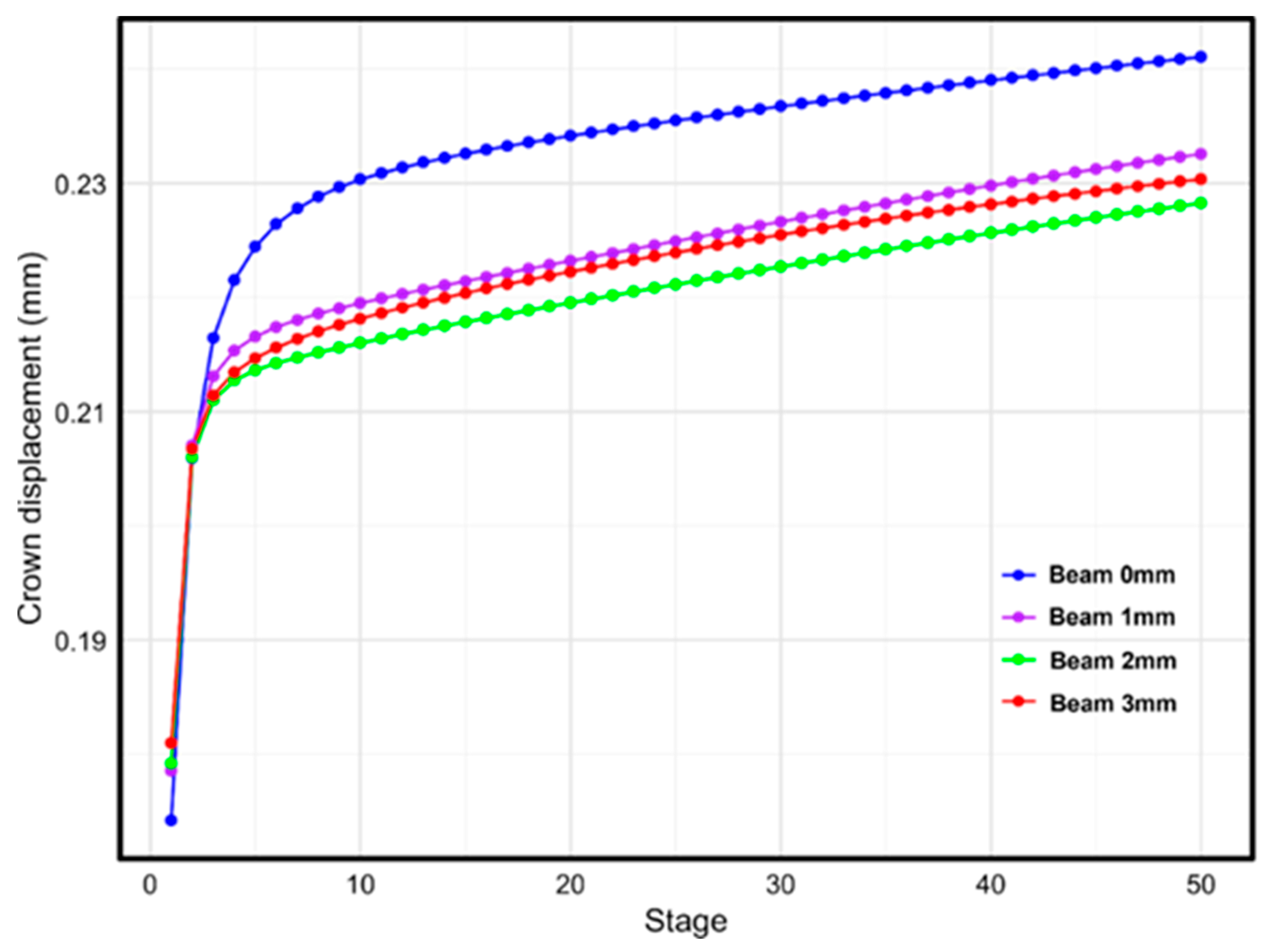
Quantitative analysis of crown displacement revealed a gradual increase in displacement across all groups as the simulation progressed through each treatment stage. At Stage 1, the initial displacement ranged from 0.174 mm in Group 0 to 0.181 mm in Group 3, showing a slight upward trend with the increasing beam width. By Stage 50, the final displacement was the highest in Group 0 (0.241 mm). However, no clear linear relationship was observed between the beam width and final displacement (
Figure 2). The final displacements were ranked as follows: Group 0 (0.241 mm) > Group 1 (0.233 mm) > Group 3 (0.230 mm) > Group 2 (0.228 mm). These findings suggest that although the presence of a beam design influences the tooth movement pattern, the effect is not directly proportional to the beam width.
Figure 2.
Canine crown displacement patterns according to beam width variations during treatment progression. The graph demonstrates the relationship between beam width (0, 1, 2, and 3 mm) and cumulative crown displacement over 50 treatment stages, illustrating the biomechanical effects of extraction space design modifications on tooth movement characteristics.
3.2. Tipping Analysis
In the analysis of tipping movement, the initial tipping angle at Stage 1 demonstrated a slightly increasing trend with a greater beam width, ranging from 0.695° in Group 0 to 0.724° in Group 3. As the simulation progressed, the tipping angle decreased across all of the groups, indicating a progressive correction of the angular displacement. By Stage 50, the final tipping angles ranged from 0.556° (Group 0) to 0.420° (Group 2) (
Figure 3). Among all of the groups, Group 2 exhibited the smallest final tipping angle, indicating the most effective control of unwanted tipping in this group. Moreover, Groups 2 and 3 showed a more substantial reduction in tipping angle than Groups 0 and 1. These results suggest that the presence of a beam design, particularly with a moderate beam width, plays a significant role in mitigating excessive tipping during distal canine movement.
Figure 3.
Changes in canine tipping angle according to beam width variations during treatment progression. The graph shows the relationship between beam width (0, 1, 2, and 3 mm) and canine tipping patterns over 50 treatment stages, illustrating tipping control effectiveness.
Figure 3.
Changes in canine tipping angle according to beam width variations during treatment progression. The graph shows the relationship between beam width (0, 1, 2, and 3 mm) and canine tipping patterns over 50 treatment stages, illustrating tipping control effectiveness.
3.3. Rotation Analysis
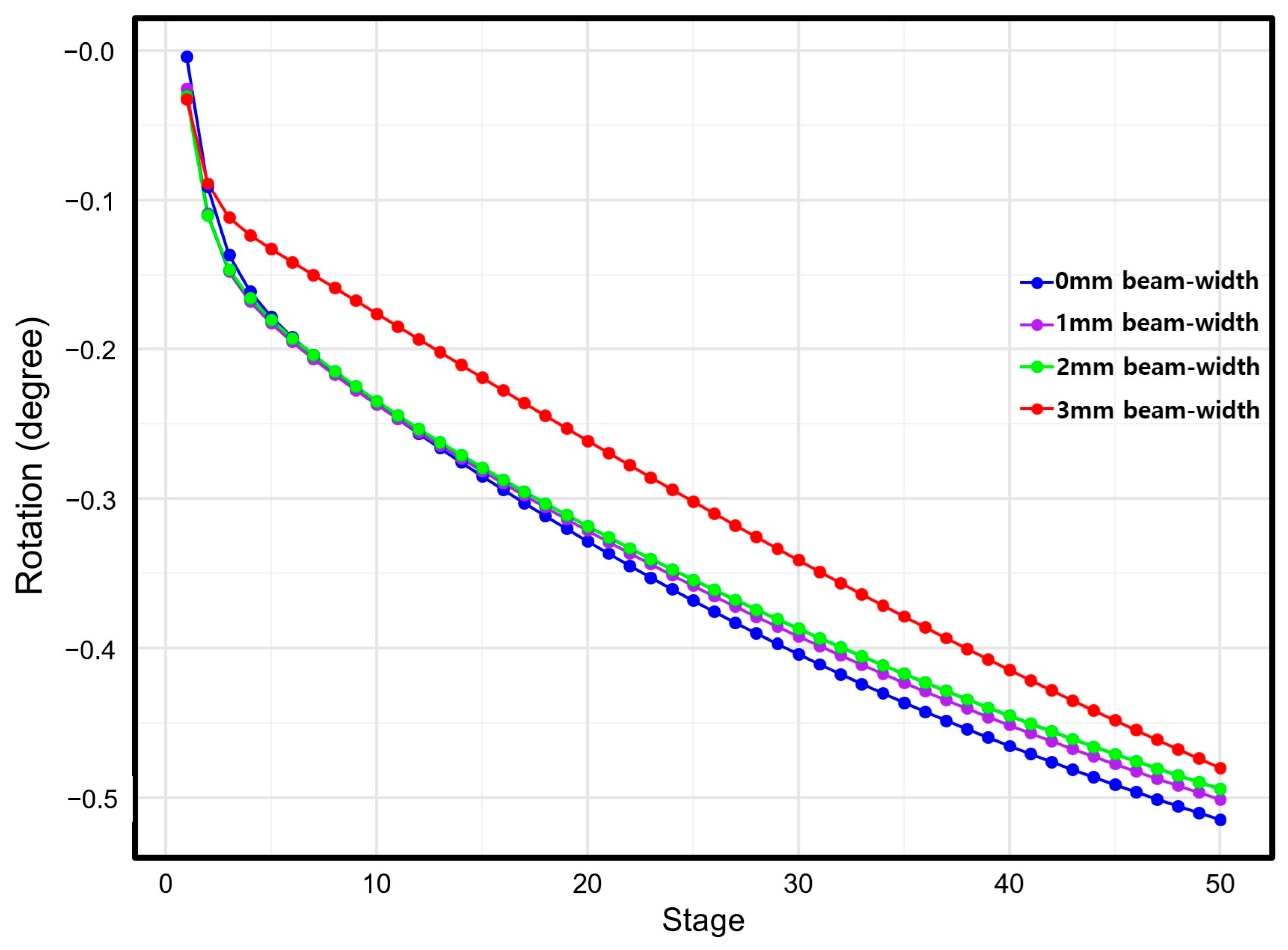
In the rotation analysis, the initial rotation angle at Stage 1 ranged from −0.004° in Group 0 to −0.033° in Group 3, with the absolute value of rotation increasing with the increase in beam width. Across all groups, the absolute value of the rotation angle progressively increased with each simulation stage. At Stage 50, the final rotation angles ranged from −0.515° (Group 0) to −0.480° (Group 3) (
Figure 4). The final rotation angles, in terms of absolute value, were as follows: Group 0 (−0.515°) > Group 1 (−0.501°) > Group 2 (−0.494°) > Group 3 (−0.480°). These results indicate that Group 3, which incorporated a beam of 3 mm width, was the most effective at controlling unwanted rotational movement of the canine.
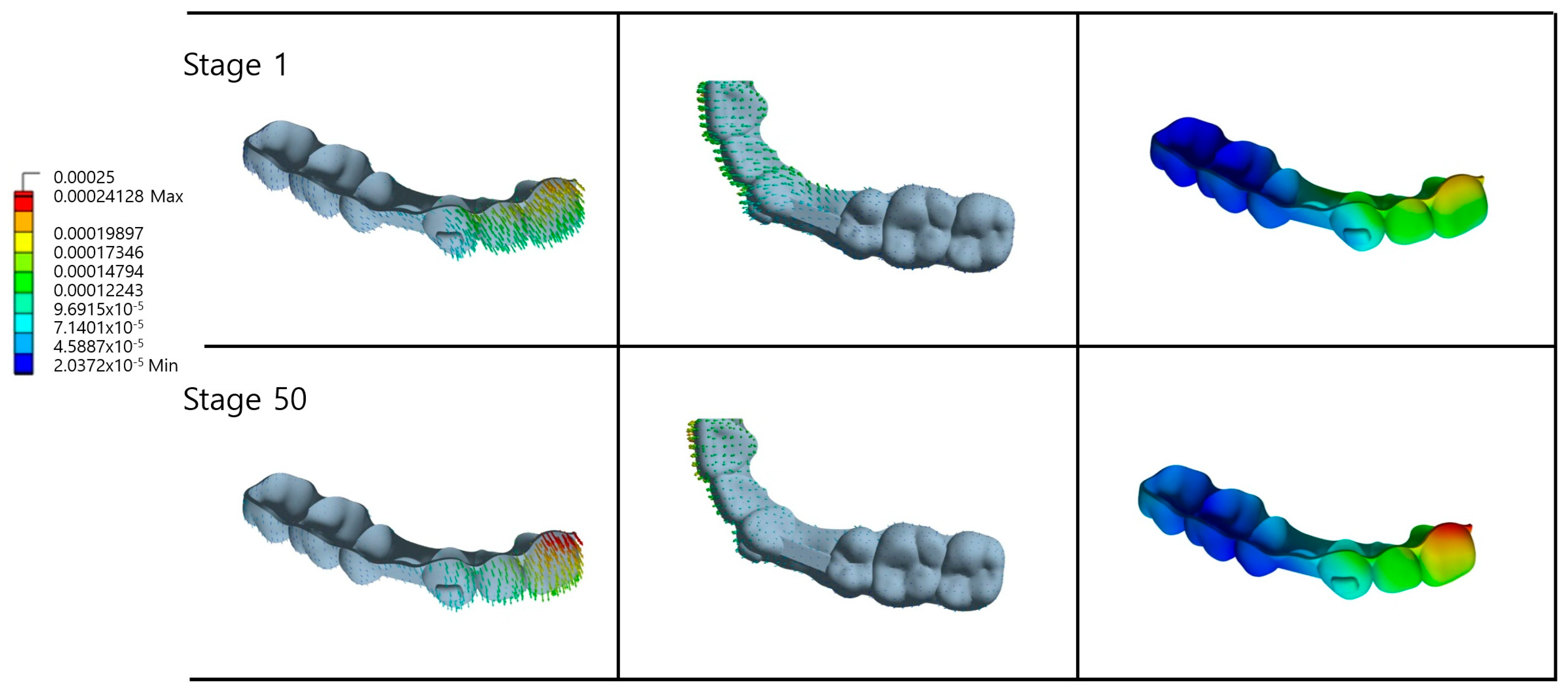
3.4. CA Deformation Analysis
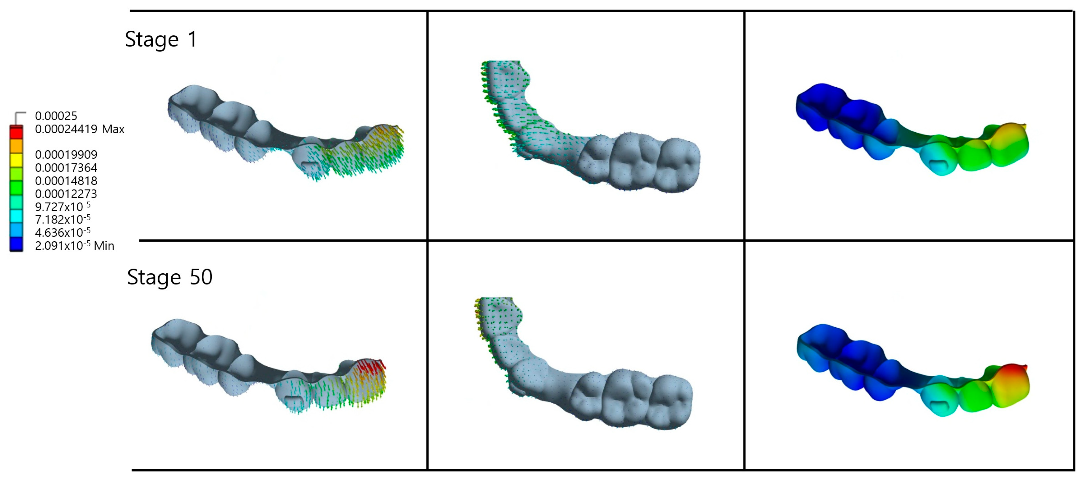
In Group 0 the CA exhibited notable deformation, particularly along the lingual and buccal surfaces of the maxillary anterior teeth (
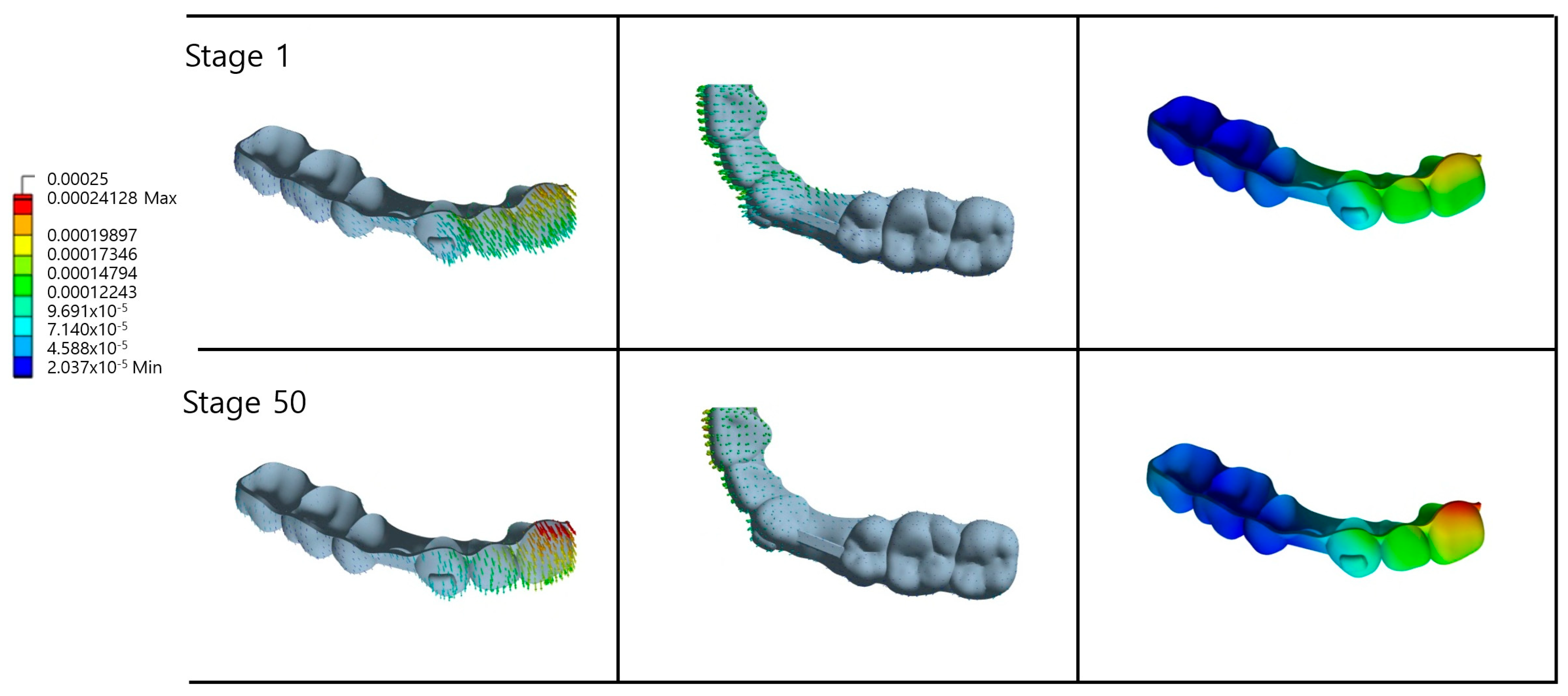
Figure 5.). The magnitude and pattern of deformation evolved from Stage 1 to Stage 50, reflecting progressive changes in the distribution of forces and areas of stress concentration over time. Similar deformation patterns were observed in Groups 1 and 2 (
Figure 6 and
Figure 7). However, a comparison of the aligner shapes between Stage 1 and Stage 50 revealed marked differences in both the overall geometry of the appliance and the spatial distribution of deformation. Notably, the gingival margin of the maxillary central incisor showed a pronounced increase in deformation, suggesting cumulative mechanical stress in that region during simulated treatment progression.
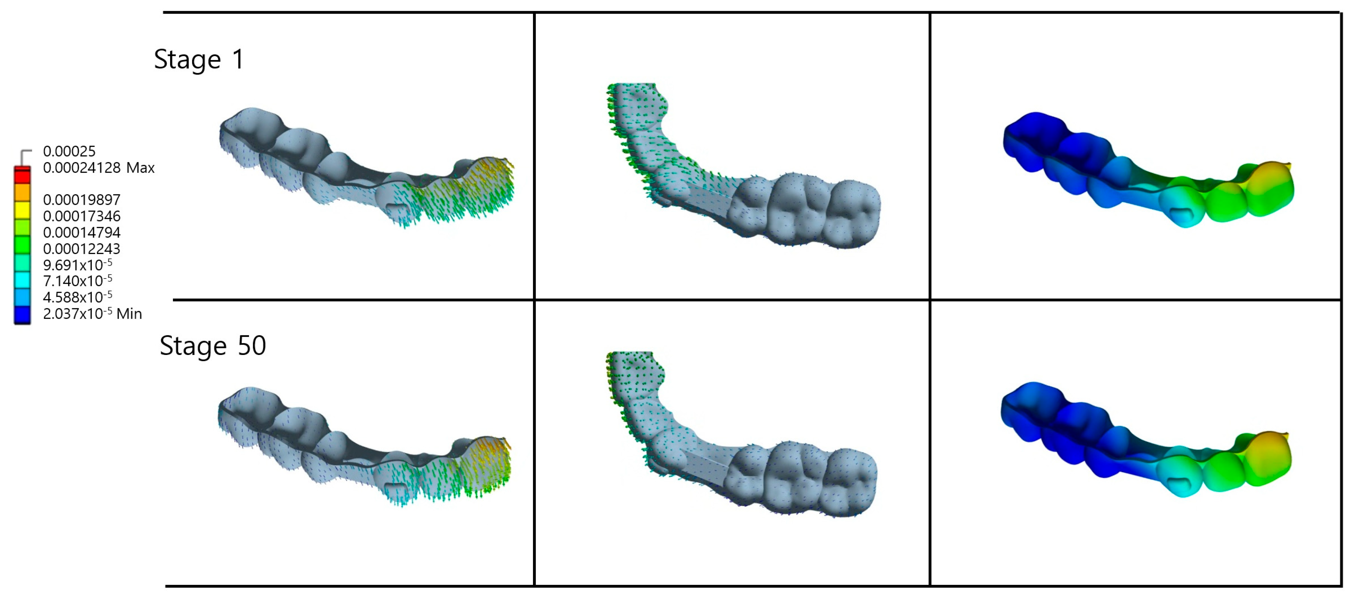
Compared to the other experimental groups, Group 3 demonstrated significantly less deformation of the gingival margin at the maxillary central incisor, indicating enhanced structural rigidity and superior deformation resistance in this region (
Figure 8). The 3 mm beam width configuration provided substantially greater structural support within the extraction space relative to the alternative conditions, resulting in a distinctive deformation pattern around both the canine area and extraction sites. At Stage 50, deformation in the posterior canine region exhibited a more uniform distribution, directly correlating with the superior control of canine rotation in Group 3 as demonstrated in previous analyses. This enhanced performance can be attributed to the thicker beam structure, which effectively distributes the orthodontic forces across a broader surface area while simultaneously increasing the overall appliance rigidity. Consequently, this configuration facilitated a more stable force and moment transmission, promoting optimal bodily movement of the canine rather than uncontrolled tipping or rotation.
3.5. Force and Moment Analysis
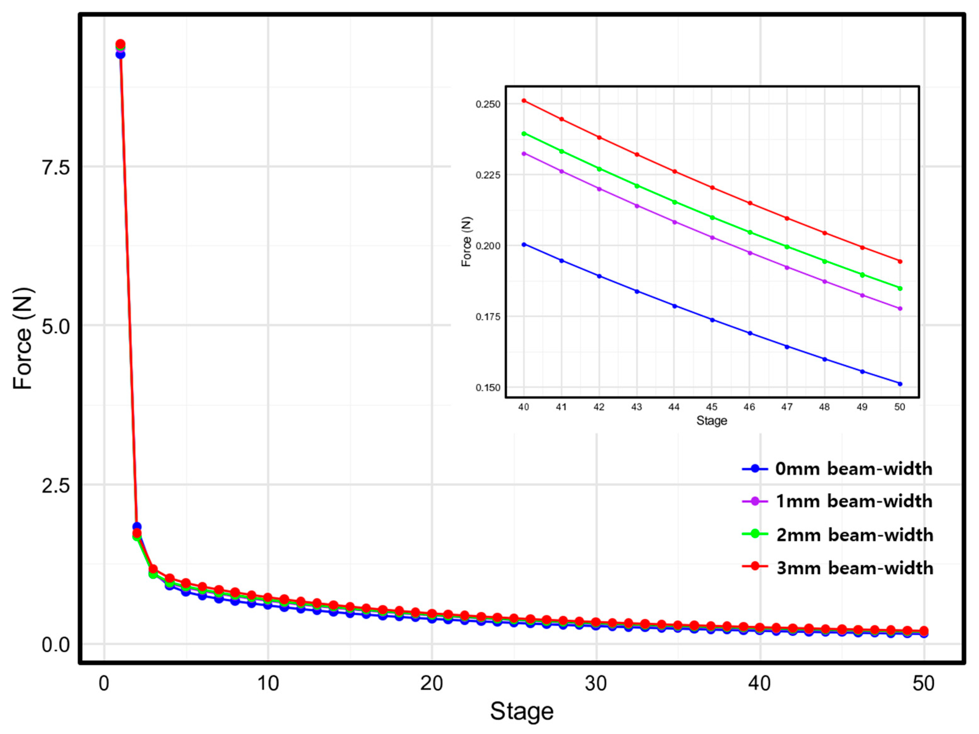
Force analysis revealed a consistent pattern of gradual reduction in the force magnitude applied to the canine throughout treatment progression across all experimental groups. Initial force values at Stage 1 demonstrated a positive correlation with beam width, ranging from 9.25 N in the control group (Group 0) to 9.41 N in the maximum beam width configuration (Group 3), indicating that increased beam dimensions enhance initial force transmission (
Figure 9).
All groups exhibited a characteristic biphasic force decay pattern, with rapid force reduction occurring during the initial treatment stages, followed by gradual stabilization in the subsequent phases. This force profile reflects the typical biomechanical response of CA systems during orthodontic tooth movement.
Final force values at Stage 50 ranged from 0.15 N (Group 0) to 0.19 N (Group 3), demonstrating that wider beam configurations maintained higher residual force levels throughout the treatment sequence. This finding suggests that an increased beam width enhances force sustainability and consistency during orthodontic treatment.
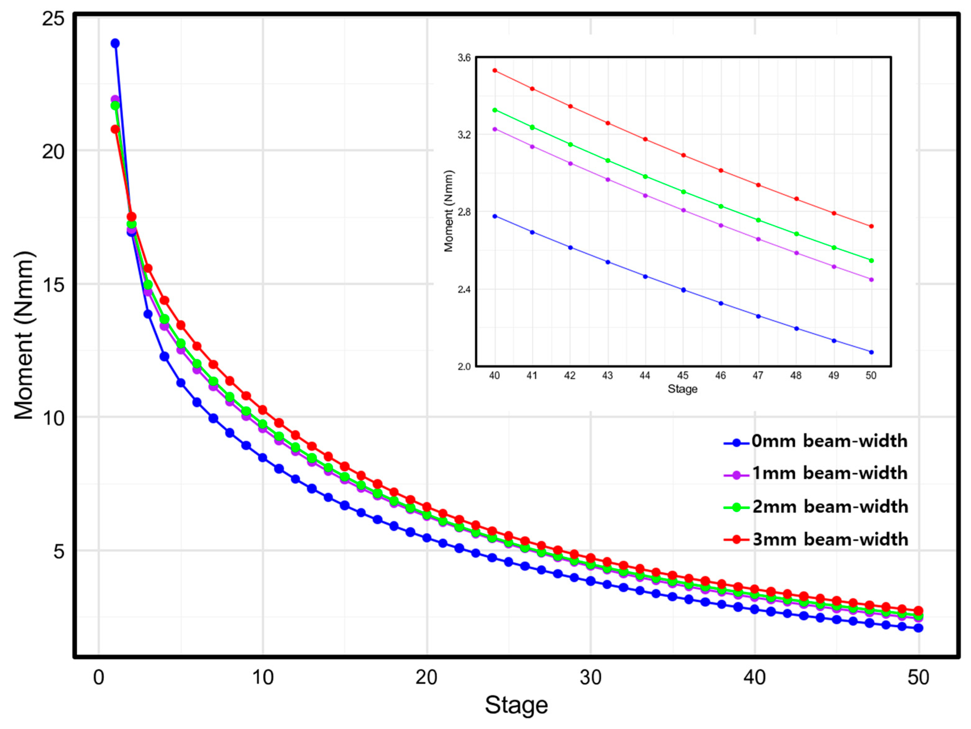
In the moment analysis, initial moment values at Stage 1 exhibited an inverse relationship with beam width, decreasing from 24.0 Nmm in the control group (Group 0) to 20.8 Nmm in the maximum beam width configuration (Group 3) (
Figure 10). The moment values demonstrated a consistent gradual reduction throughout treatment progression across all experimental groups, following a decay pattern similar to that noted in the force analysis. However, the final moment values at Stage 50 revealed a contrasting trend, ranging from 2.1 Nmm (Group 0) to 2.7 Nmm (Group 3), with higher beam widths maintaining superior moment retention in the later stages.
4. Discussion
Previous studies investigating the biomechanical effects of CA design variations on extraction space closure have provided important insights into CA treatment optimization. Mao et al. demonstrated that the vertical height of the clear aligner extraction space significantly influenced the patterns of anterior tooth retraction and canine tipping when clear aligner extraction space height parameters were systematically varied [
17,
18]. Another finite element study [
16] examined effects of different extraction space designs (non-pontic, full-pontic, half-pontic, and beam design configurations) and initially observed similar crown displacements, distal inclinations, and distal rotations across all designs. However, as tooth movement progressed, canine movement patterns diverged significantly among the various designs, with the beam design configuration demonstrating superior effectiveness in controlling bodily tooth movement. These previous research findings indicate that extraction space configuration is a critical factor influencing the biomechanical performance of CA treatments. Building on this foundation, the present study systematically analyzed effects of buccolingual width variations in the extraction space on canine tooth movement patterns, providing novel insights into the optimal beam design parameters for enhanced treatment outcomes.
The results of this study clearly demonstrate that both the presence and width of the beam significantly influence the biomechanical response during canine retraction. While distal movement of the canine was observed across all experimental groups, the movement patterns varied considerably depending on the width of the buccolingual beam. Group 0 (0 mm beam width) exhibited the greatest crown displacement and the most pronounced tipping behavior. This indicates that without structural support in the extraction space, tooth movement control is compromised, resulting in an increase in unwanted tipping components. These findings are consistent with those of Mao et al., who demonstrated that lower heights were effective for bodily movement, suggesting that the tipping effect was enhanced because the aligner completely bypassed the extraction space and transmitted forces only to the adjacent teeth, thereby displacing the line of force away from the center of resistance of the crown [
17,
18]. Conversely, as the beam width increases, both the final distal displacement and final tipping angles decrease. These results indicate that a greater beam width not only reduces the linear displacement, but also effectively controls unwanted tipping movements, thereby promoting more favorable bodily tooth movement [
21,
22,
23].
Previous studies have demonstrated that the utility of design elements, such as attachments, significantly depends on their ability to accurately transmit forces and moments to enhance the efficiency and predictability of tooth movement [
11,
24,
25,
26,
27]. Similarly, the results of this study revealed that the buccolingual width of the extraction space is a critical design variable that influences force and moment transmission, thereby controlling tooth movement patterns. The analysis of forces and moments applied to the canine demonstrated a clear correlation with the beam width parameters. As the beam width increased, the initial force transmitted to the canine increased proportionally, whereas the initial moment decreased inversely. Specifically, when beam width increased from 0 mm to 3 mm, the initial force applied to the canine rose from approximately 9.2 N to 9.4 N, while the initial moment decreased from 24.0 Nmm to 20.8 Nmm. As tooth movement progressed, force patterns remained consistent with the initial observations; however, moment characteristics exhibited a reversal, with higher values maintained in wider beam configurations during the later treatment stages. The observed force reduction throughout treatment reflects the stress relaxation phenomenon inherent in thermoplastic materials, representing a characteristic response to the progressive mismatch between CA geometry and evolving tooth positions [
28,
29,
30,
31,
32]. However, both the rate and pattern of this force reduction varied significantly with the beam width because the beam geometry fundamentally altered the dynamic force transmission characteristics throughout the treatment sequence. An optimal force range exists for different types of tooth movement. Studies by Proffit et al. have established 70–120 g (approximately 0.70–1.20 N) as the optimal force range for bodily movement [
33,
34,
35,
36]. In the groups in the present study, the initial Stage 1 values represent the maximum forces occurring upon appliance insertion. As previously mentioned, the stage numbers cannot be directly equated with temporal progression. Nevertheless, when considered as a sequential process corresponding to tooth movement, the forces following the initial appliance insertion (Stages 1–2) remain within the optimal range for bodily movement through Stages 3–10 and gradually diminish thereafter. For bodily tooth movement, a specific moment-to-force (M/F) ratio is required to direct the force through the center of resistance or counteract the moments generated by force application at the center of resistance. When a force is applied to the crown, an inevitable moment occurs that causes tooth tipping. In Group 0, the M/F ratio increased continuously from an initial value of 2.594 to 13.693 at Stage 50, while other groups achieved final values of 13.775, 13.776, and 14.003, respectively. The combination of forces and moments transmitted to the canine across all experimental groups did not achieve the ideal M/F ratio for pure bodily tooth movement. Although Group 3 generated larger initial forces, the final tooth displacement was marginally smaller than that of Group 0. This indicates that the tooth movement pattern manifested as root uprighting following initial crown tipping, rather than achieving a true ‘bodily movement’ force system from treatment initiation. This sequential movement pattern suggests a controlled tipping-and-uprighting mechanism rather than a pure translation: the deformation patterns of the CA varied significantly according to the beam width implemented in the extraction space. Notably, compared to the other configurations, the 3 mm beam width design demonstrated minimal deformation in the gingival margin area of the maxillary central incisor. This reduced deformation can be attributed to the ability of the beam structure to locally enhance the structural rigidity of the aligner within the extraction space region. The presence of the beam directly influenced the mechanical properties of the aligner material. The stiffness of the aligner materials plays a crucial role in transmitting the necessary light forces while maintaining a high elastic limit to prevent permanent deformation [
17,
18,
37]. The 3 mm beam width design significantly enhanced the aligner’s deformation resistance capabilities.
CA deformation results directly from the applied stress and the material’s inherent deformation resistance. Consequently, the reduced deformation in specific regions indicates either a lower applied stress in that area or enhanced deformation resistance under stress conditions. The 3 mm beam width design increases the local stiffness, enabling the aligner to maintain its intended geometry while transmitting more controlled forces to the adjacent teeth.
This enhanced structural performance aligns with previous research findings demonstrating that strategic ‘extraction space area’ modifications can facilitate localized control and minimize unwanted deformation patterns [
37]. Finite element analysis is a valuable tool for evaluating biomechanical effects of orthodontic appliance designs. The selection of finite element analysis as the primary evaluation method was based on several critical considerations. FEM provides unparalleled capabilities for analyzing complex three-dimensional stress and strain distributions within orthodontic appliances and surrounding biological structures, which would be impossible to measure directly in clinical settings [
38]. The iterative simulation approach allows comprehensive evaluation of dynamic biomechanical changes throughout treatment progression, providing insights unattainable from single-time-point analyses.
Additionally, the ethical and practical limitations of conducting controlled clinical trials with multiple design variations make FEM essential for preliminary investigations. Testing four different beam width configurations in human subjects would require extensive treatment periods and expose patients to potentially suboptimal protocols. FEM enables systematic parameter variation and comparative analysis without these constraints, allowing for the identification of optimal design parameters before clinical implementation. However, it has inherent limitations [
11]. The finite element model employed in this study utilizes simplified geometric assumptions and idealized material properties, representing a static analysis that does not account for dynamic bone remodeling processes [
38]. Furthermore, numerous variables encountered in clinical practice, including variations in patient compliance and individual differences in biological responses, have not been incorporated into the computational model [
28,
29,
30,
31,
32]. Although simulation studies have demonstrated clinically acceptable accuracy in treatment planning applications, discrepancies between predicted and actual outcomes have been reported for complex tooth movements [
39]. Therefore, although the results of this study provide valuable biomechanical insights into beam design optimization, further validation through prospective clinical trials is essential to confirm the effects of beam width variations on tooth movement patterns and tipping control in clinical practice.
5. Conclusions
This finite element study evaluated the biomechanical effects of buccolingual beam width variations (0, 1, 2, and 3 mm) on canine distal movement in maxillary first premolar extraction spaces during clear aligner treatment. The results demonstrate that beam width significantly influences canine movement patterns, with wider configurations providing superior control of unwanted tooth movements.
Specifically, the 2 mm beam width achieved the most effective tipping control (0.420° final angulation), while the 3 mm beam width demonstrated optimal rotational control (−0.480°) and minimal aligner deformation. Force analysis revealed that increased beam width enhanced both initial force transmission (9.25N → 9.41N) and sustained force delivery throughout treatment progression.
Based on these findings, incorporating beam widths of 2–3 mm in extraction space design represents an optimal approach for promoting controlled canine bodily movement during clear aligner therapy. These results provide evidence-based guidance for extraction space design optimization beyond purely aesthetic considerations, contributing to improved treatment predictability in complex orthodontic cases.
Author Contributions
Conceptualization, H.L., K.K., S.-S.K. and Y.-I.K.; methodology, K.K., Y.-K.C., S.-H.K. and S.-S.K.; formal analysis, H.L., Y.-K.C., S.-H.K., S.-S.K. and Y.-I.K.; writing—original draft preparation, H.L., S.-S.K. and Y.-I.K.; writing—review and editing, H.L., K.K., Y.-K.C., S.-H.K., S.-S.K. and Y.-I.K.; funding acquisition, Y.-I.K. All authors have read and agreed to the published version of the manuscript.
Funding
This work was supported by the National Research Foundation for Korea (NRF) grant funded by the Korean Government (MSIT) (RS-2025-00523024).
Institutional Review Board Statement
The study protocol was approved by the Institutional Review Board (IRB) of Pusan National University Dental Hospital (IRB No. 2025-05-014).
Informed Consent Statement
Informed consent was obtained from all subjects involved in the study.
Data Availability Statement
The original contributions presented in this study are included in the article. Further inquiries can be directed to the corresponding authors.
Conflicts of Interest
The authors declare no conflicts of interest.
References
- Liu, L.; Song, Q.; Zhou, J.; Kuang, Q.; Yan, X.; Zhang, X.; Shan, Y.; Li, X.; Long, H.; Lai, W. The effects of aligner overtreatment on torque control and intrusion of incisors for anterior retraction with clear aligners a finite-element study. Am. J. Orthod. Dentofac. Orthop. 2022, 162, 33–41. [Google Scholar] [CrossRef] [PubMed]
- Karsli, N.; Ocak, I.; Gökcek, S.; Özsoy, Ö.P. Evaluation of the effect of attachments on torque control of palatally positioned maxillary lateral teeth with clear aligners: Finite element analysis. Korean J. Orthod. 2025, 55, 58–68. [Google Scholar] [CrossRef]
- Cheng, Y.; Liu, X.; Chen, X.; Li, X.; Fang, S.; Wang, W.; Ma, Y.; Jin, Z. The three-dimensional displacement tendency of teeth depending on incisor torque compensation with clear aligners of different thicknesses in cases of extraction: A finite element study. BMC Oral Health 2022, 22, 499. [Google Scholar] [CrossRef] [PubMed]
- Meng, X.; Wang, C.; Xu, W.; Wang, R.; Zheng, L.; Wang, C.; Aversa, R.; Fan, Y. Effects of different designs of orthodontic clear aligners on the maxillary central incisors in the tooth extraction cases: A biomechanical study. BMC Oral Health 2023, 23, 416. [Google Scholar] [CrossRef]
- Zhang, N.; Bai, Y.; Ding, X.; Zhang, Y. Preparation and characterization of thermoplastic materials for invisible orthodontics. Dent. Mater. J. 2011, 30, 954–959. [Google Scholar] [CrossRef] [PubMed]
- Kawamura, J.; Ojima, K.; Nanda, R. Effect of attachment type on distal bodily movement of the maxillary canine in aligner orthodontics: A finite element study. Angle Orthod. 2023, 93, 566–571. [Google Scholar] [CrossRef]
- Li, Q.; Xu, B.; Fang, D.; Yang, K. Impacts of surface wear of attachments on maxillary canine distalization with clear aligners: A three-dimensional finite element study. Front. Bioeng. Biotechnol. 2025, 13, 1530133. [Google Scholar] [CrossRef]
- Zhu, G.Y.; Zhang, B.; Yao, K.; Lu, W.X.; Peng, J.J.; Shen, Y.; Zhao, Z.-H. Finite element analysis of the biomechanical effect of clear aligners in extraction space closure under different anchorage controls. Am. J. Orthod. Dentofac. Orthop. 2023, 163, 628–644. [Google Scholar] [CrossRef]
- Qiang, R.; Wu, J.; Gao, J.; Chen, H.; Xu, J.; Jin, Z.; Ma, Y. An integrated approach to posterior anchorage preparation and incisor torque compensation in premolar extraction cases using clear aligners. BMC Oral Health 2025, 25, 558. [Google Scholar] [CrossRef]
- Yang, Y.; Yang, R.; Liu, L.; Zhang, X.; Jiang, Q.; Fan, Q.; Zhang, H.; Long, H.; Lai, W. The effects of aligner anchorage preparation on mandibular first molars during premolar-extraction space closure with clear aligners: A finite element study. Am. J. Orthod. Dentofac. Orthop. 2023, 164, 226–238. [Google Scholar] [CrossRef]
- Jin, X.; Tian, X.; Hui, V.L.Z.; Zheng, Y.; Song, J.; Han, X. The effect of enhanced structure in the posterior segment of clear aligners during anterior retraction: A three dimensional finite element and experimental model analysis. Prog. Orthod. 2024, 25, 3. [Google Scholar] [CrossRef]
- Lyu, X.; Cao, X.; Yan, J.; Zeng, R.; Tan, J. Biomechanical effects of clear aligners with different thicknesses and gingival-margin morphology for appliance design optimization. Am. J. Orthod. Dentofac. Orthop. 2023, 164, 239–252. [Google Scholar] [CrossRef] [PubMed]
- Elshazly, T.M.; Keilig, L.; Salvatori, D.; Chavanne, P.; Aldesoki, M.; Bourauel, C. Effect of trimming line design and edge extension of orthodontic aligners on force transmission: An in vitro study. J. Dent. 2022, 125, 104276. [Google Scholar] [CrossRef]
- Grant, J.; Foley, P.; Bankhead, B.; Miranda, G.; Adel, S.M.; Kim, K.B. Forces and moments generated by 3D direct printed clear aligners of varying labial and lingual thicknesses during lingual movement of maxillary central incisor: An in vitro study. Prog. Orthod. 2023, 24, 23. [Google Scholar] [CrossRef]
- Akan, B.E.K.; Kircelli, B.H.; Bozkurt, A.P.; Gogen, H. A finite element analysis of the effects of semipontic design on tooth movement during mesialization of the mandibular second molar with clear aligners. Am. J. Orthod. Dentofac. Orthop. 2024, 166, 490–502. [Google Scholar] [CrossRef] [PubMed]
- Baek, S.E.; Kim, K.; Choi, Y.K.; Kim, S.H.; Kim, S.S.; Kim, K.B.; Kim, Y.-I. Effects of clear aligner edentulous space design on distal canine movement: An iterative finite element analysis in cases involving extraction. Korean J. Orthod. 2025, 55, 193–201. [Google Scholar] [CrossRef] [PubMed]
- Mao, B.; Tian, Y.; Xiao, Y.; Liu, Y.; Liu, D.; Li, J.; Zhou, Y. Biomechanical effects of clear aligner with different shape design at extraction space area during anterior teeth retraction. Orthod. Craniofac. Res. 2024, 27, 740–749. [Google Scholar] [CrossRef]
- Cao, Y.; Wang, Z.W.; Chen, D.; Liu, L.; Li, D.X.; Li, N.; Ying, S.-Q.; Liu, X.; Jin, F. The effect of space arrangement between anterior teeth on their retraction with clear aligners in first premolar extraction treatment: A finite element study. Prog. Orthod. 2023, 24, 39. [Google Scholar] [CrossRef]
- Yokoi, Y.; Arai, A.; Kawamura, J.; Uozumi, T.; Usui, Y.; Okafuji, N. Effects of Attachment of Plastic Aligner in Closing of Diastema of Maxillary Dentition by Finite Element Method. J. Healthc. Eng. 2019, 2019, 1075097. [Google Scholar] [CrossRef]
- Kawamura, J.; Tamaya, N. A finite element analysis of the effects of archwire size on orthodontic tooth movement in extraction space closure with miniscrew sliding mechanics. Prog. Orthod. 2019, 20, 3. [Google Scholar] [CrossRef]
- Izhar, A.; Singh, G.; Goyal, V.; Singh, R.; Gupta, N.; Pahuja, P. Comparative Assessment of Clinical and Predicted Treatment Outcomes of Clear Aligner Treatment: An in Vivo Study. Turk. J. Orthod. 2019, 32, 229–235. [Google Scholar] [CrossRef]
- Lagravère, M.O.; Flores-Mir, C. The treatment effects of Invisalign orthodontic aligners: A systematic review. J. Am. Dent. Assoc. 2005, 136, 1724–1729. [Google Scholar] [CrossRef]
- Rossini, G.; Parrini, S.; Castroflorio, T.; Deregibus, A.; Debernardi, C.L. Efficacy of clear aligners in controlling orthodontic tooth movement: A systematic review. Angle Orthod. 2015, 85, 881–889. [Google Scholar] [CrossRef]
- Rossini, G.; Schiaffino, M.; Parrini, S.; Sedran, A.; Deregibus, A.; Castroflorio, T. Upper Second Molar Distalization with Clear Aligners: A Finite Element Study. Appl. Sci. 2020, 10, 7739. [Google Scholar] [CrossRef]
- Ravera, S.; Castroflorio, T.; Garino, F.; Daher, S.; Cugliari, G.; Deregibus, A. Maxillary molar distalization with aligners in adult patients: A multicenter retrospective study. Prog. Orthod. 2016, 17, 12. [Google Scholar] [CrossRef]
- Garino, F.; Castroflorio, T.; Daher, S.; Ravera, S.; Rossini, G.; Cugliari, G.; Deregibus, A. Effectiveness of composite attachments in controlling upper-molar movement with aligners. J. Clin. Orthod. 2016, 50, 341–347. [Google Scholar]
- Badawi, H.M.; Toogood, R.W.; Carey, J.P.R.; Heo, G.; Major, P.W. Three-dimensional orthodontic force measurements. Am. J. Orthod. Dentofac. Orthop. 2009, 136, 518–528. [Google Scholar] [CrossRef]
- Skaik, A.; Wei, X.L.; Abusamak, I.; Iddi, I. Effects of time and clear aligner removal frequency on the force delivered by different polyethylene terephthalate glycol-modified materials determined with thin-film pressure sensors. Am. J. Orthod. Dentofac. Orthop. 2019, 155, 98–107. [Google Scholar] [CrossRef]
- Hahn, W.; Dathe, H.; Fialka-Fricke, J.; Fricke-Zech, S.; Zapf, A.; Kubeen-Meesenburg, D.; Sadat-Khonsari, R. Influence of thermoplastic appliance thickness on the magnitude of force delivered to a maxillary central incisor during tipping. Am. J. Orthod. Dentofac. Orthop. 2009, 136, 12.e1–12.e7. [Google Scholar] [CrossRef]
- Hahn, W.; Engelke, B.; Jung, K.; Dathe, H.; Fialka-Fricke, J.; Kubeen-Meesenburg, D.; Sadat-Khonsari, R. Initial forces and moments delivered by removable thermoplastic appliances during rotation of an upper central incisor. Angle Orthod. 2010, 80, 239–246. [Google Scholar] [CrossRef]
- Hahn, W.; Fialka-Fricke, J.; Dathe, H.; Fricke-Zech, S.; Zapf, A.; Gruber, R.; Kubein-Meesenburg, D.; Sadat-Khonsari, R. Initial forces generated by three types of thermoplastic appliances on an upper central incisor during tipping. Eur. J. Orthod. 2009, 31, 625–631. [Google Scholar] [CrossRef]
- Kwon, J.S.; Lee, Y.K.; Lim, B.S.; Lim, Y.K. Force delivery properties of thermoplastic orthodontic materials. Am. J. Orthod. Dentofac. Orthop. 2008, 133, 228–234. [Google Scholar] [CrossRef]
- Lear, M.; Akbari, A.; Robertson, O.; Magura, J.; Bojrab, A.; Eckert, G.; Chen, J.; Conley, R.S.; Turkkahraman, H. In Vitro Comparison of Direct Attachment Shape and Size on the Orthodontic Forces and Moments Generated by Thermoplastic Aligners During Expansion. Orthod. Craniofac. Res. 2025, 28, 242–252. [Google Scholar] [CrossRef]
- Proffit, W.R. Contemporary Orthodontics, 6th ed.; Elsevier: Philadelphia, PA, USA, 2018. [Google Scholar]
- Wu, J.L.; Liu, Y.F.; Peng, W.; Dong, H.Y.; Zhang, J.X. A Biomechanical Case Study on the Optimal Orthodontic Force on the Maxillary Canine Tooth Based on Finite Element Analysis. J. Zhejiang Univ. Sci. B 2018, 19, 535–546. [Google Scholar] [CrossRef]
- Theodorou, C.I.; Kuijpers-Jagtman, A.M.; Bronkhorst, E.M.; Wagener, F. Optimal Force Magnitude for Bodily Orthodontic Tooth Movement With Fixed Appliances: A Systematic Review. Am. J. Orthod. Dentofac. Orthop. 2019, 156, 582–592. [Google Scholar] [CrossRef]
- Sawamura, M.; Nakano, H.; Shiogama, M.; Takano, N.; Maki, K. Using digital image correlation to measure displacement and strain during involving distal movement of anterior teeth with clear aligner. Dent. Mater. J. 2023, 42, 493–500. [Google Scholar] [CrossRef]
- Kim, W.H.; Hong, K.; Lim, D.; Lee, J.H.; Jung, Y.J.; Kim, B. Optimal Position of Attachment for Removable Thermoplastic Aligner on the Lower Canine Using Finite Element Analysis. Materials 2020, 13, 3369. [Google Scholar] [CrossRef]
- Sereewisai, B.; Chintavalakorn, R.; Santiwong, P.; Nakornnoi, T.; Neoh, S.P.; Sipiyaruk, K. The accuracy of virtual setup in simulating treatment outcomes in orthodontic practice: A systematic review. BDJ Open 2023, 9, 41. [Google Scholar] [CrossRef]
Figure 4.
Progression of canine rotation angle according to beam width variations during treatment stages. The graph demonstrates how different beam widths influence canine rotational movement, with the 3 mm beam showing distinctly different rotational control compared to the other configurations.
Figure 4.
Progression of canine rotation angle according to beam width variations during treatment stages. The graph demonstrates how different beam widths influence canine rotational movement, with the 3 mm beam showing distinctly different rotational control compared to the other configurations.
Figure 5.
Clear aligner deformation patterns for a 0 mm beam width configuration. Deformation visualization at the initial (Stage 1, upper panel) and final (Stage 50, lower panel) treatment stages from three viewing perspectives: lateral view with displacement vectors (left), occlusal view (middle), and color-coded deformation magnitude mapping (right).
Figure 6.
Clear aligner deformation patterns for a 1 mm beam width configuration. Deformation visualization at the initial (Stage 1, upper panel) and final (Stage 50, lower panel) treatment stages from three perspectives: lateral view with displacement vectors, occlusal view, and quantitative color-coded mapping.
Figure 7.
Clear aligner deformation patterns for a 2 mm beam width configuration. Deformation visualization at the initial (Stage 1, upper panel) and final (Stage 50, lower panel) treatment stages from three perspectives: lateral view with displacement vectors, occlusal view, and quantitative color-coded mapping.
Figure 8.
Clear aligner deformation patterns for a 3 mm beam width configuration. Deformation visualization at the initial (Stage 1, upper panel) and final (Stage 50, lower panel) treatment stages from three perspectives: lateral view with displacement vectors, occlusal view, and quantitative color-coded mapping.
Figure 9.
Canine force-magnitude progression according to beam width during treatment stages. The main graph illustrates force decay patterns (N) over 50 treatment stages for beam widths of 0, 1, 2, and 3 mm, with an inset providing a detailed view of force sustainability during the final treatment phases (Stages 40–50).
Figure 10.
Canine moment-magnitude progression according to beam width during treatment stages. The main graph illustrates moment decay patterns (Nmm) over 50 treatment stages for beam widths of 0, 1, 2, and 3 mm, with an inset providing a detailed view of moment sustainability during the final treatment phases (Stages 40–50).
Table 1.
Properties of materials used in the finite element models.
Table 1.
Properties of materials used in the finite element models.
| Material | Young’s Modulus (MPa) | Poisson’s Ratio |
|---|
| Alveolar bone | 13,700 | 0.3 |
| Teeth | 19,600 | 0.3 |
| Clear aligner | 528 | 0.36 |
| Composite attachment | 12,500 | 0.36 |
| Periodontal ligament | 0.69 | 0.45 |
| Disclaimer/Publisher’s Note: The statements, opinions and data contained in all publications are solely those of the individual author(s) and contributor(s) and not of MDPI and/or the editor(s). MDPI and/or the editor(s) disclaim responsibility for any injury to people or property resulting from any ideas, methods, instructions or products referred to in the content. |
© 2025 by the authors. Licensee MDPI, Basel, Switzerland. This article is an open access article distributed under the terms and conditions of the Creative Commons Attribution (CC BY) license (https://creativecommons.org/licenses/by/4.0/).


 ,
, 

