


Predicting the Hydration of Ground Granulated Blast Furnace Slag and Recycled Glass Blended Cements

 ,
, 
 , and
, and
Abstract
1. Introduction
- 1.
- Improve process efficiency through procedural change and plant modernization.
- 2.
- Use of alternative fuels and alternative raw materials.
- 3.
- Replace Portland cement clinker with supplementary cementitious materials (SCMs).
- 4.
- Increase the use of high-strength concrete and so reduce the amount used in a single application.
- 5.
- Develop alternative low-carbon binders not based on Portland cement.
- 6.
- Carbon capture, storage and use (CCS, CCSU).
1.1. Previous Research
1.2. Recycled Glass Powder as a Supplementary Cementitious Material
1.3. Hydration of Blended Recycled Glass Powder in CEM II/A-LL Slag Cements
- (1)
- A control sample comprising 50% GGBS and 50% CEM II/A-LL (all quantities by mass) but without RCGP.
- (2)
- A cement paste containing 60% CEM II/A-LL combined with 40% of the RCGP–GGBS development blend.
- (3)
- A cement paste containing 40% CEM II/A-LL combined with 60% of the RCGP–GGBS development blend.
- (4)
- ‘Standard’ Portland-Limestone cement (CEM II/A-LL) containing 10.48% CaCO3 (measured and supplied by Ecocem France, Dunkirk works).
2. Materials and Methods
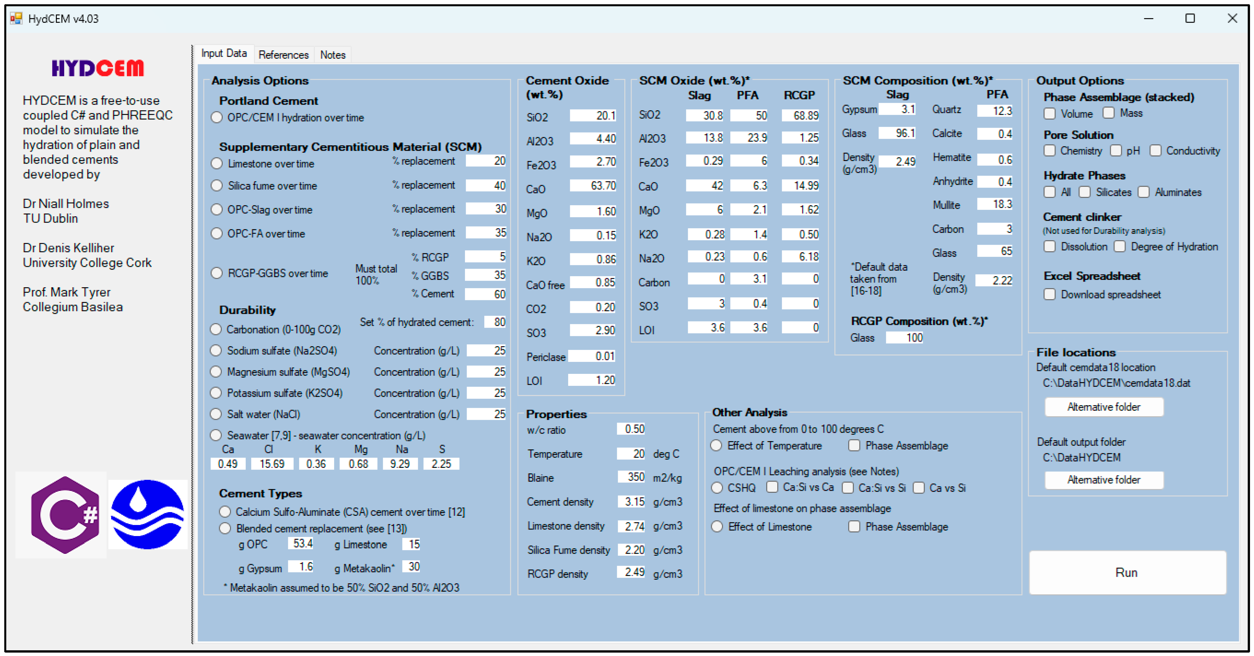
2.1. Hydration Modelling Using HYDCEM
2.2. Solid Solutions
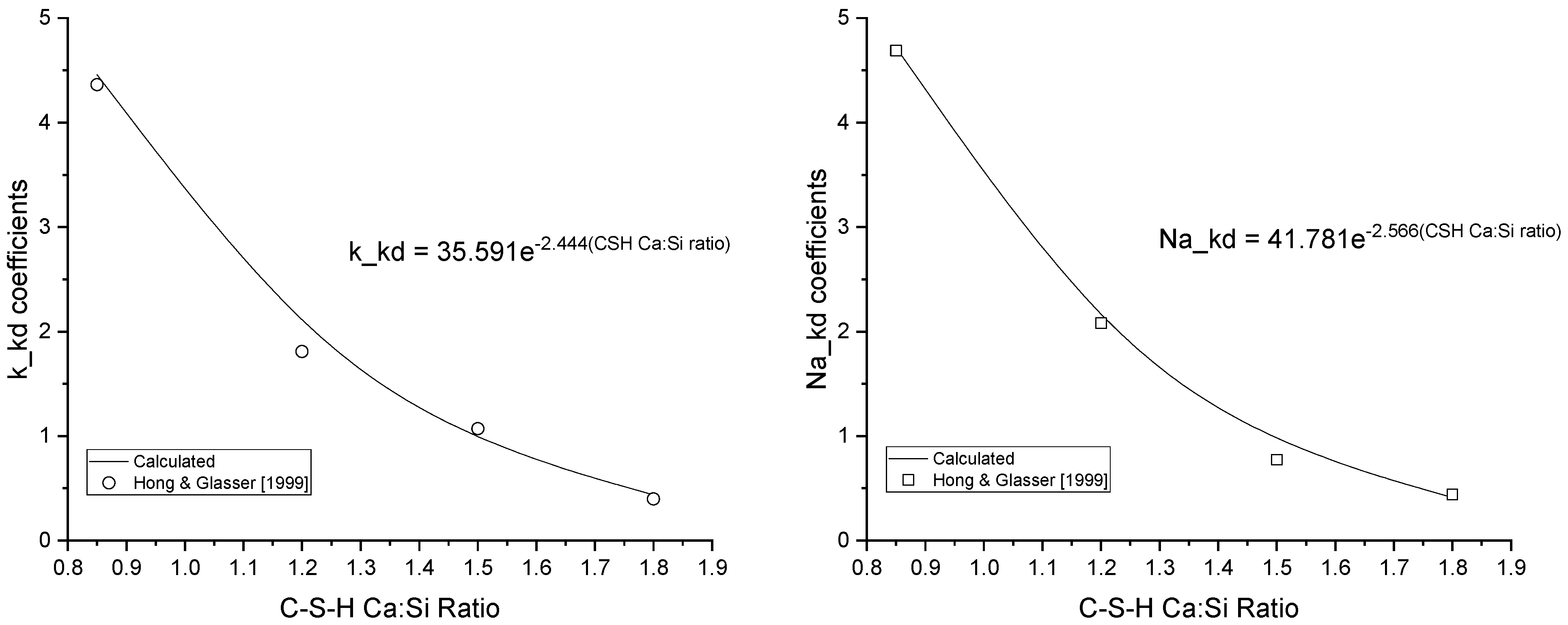
2.3. Kinetics
2.4. Clinker and Binder Dissolution
2.5. Hydration and Thermodynamic Considerations
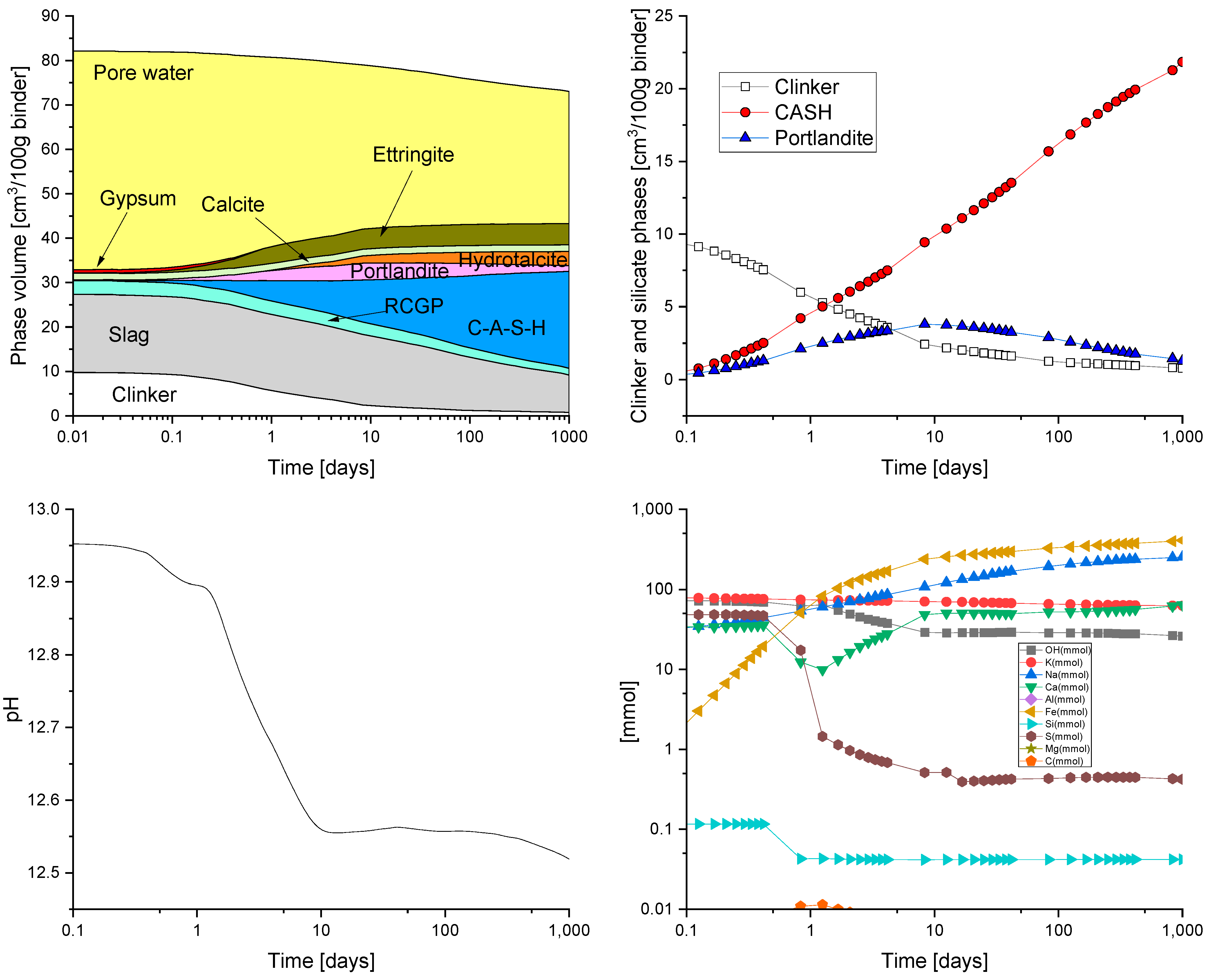
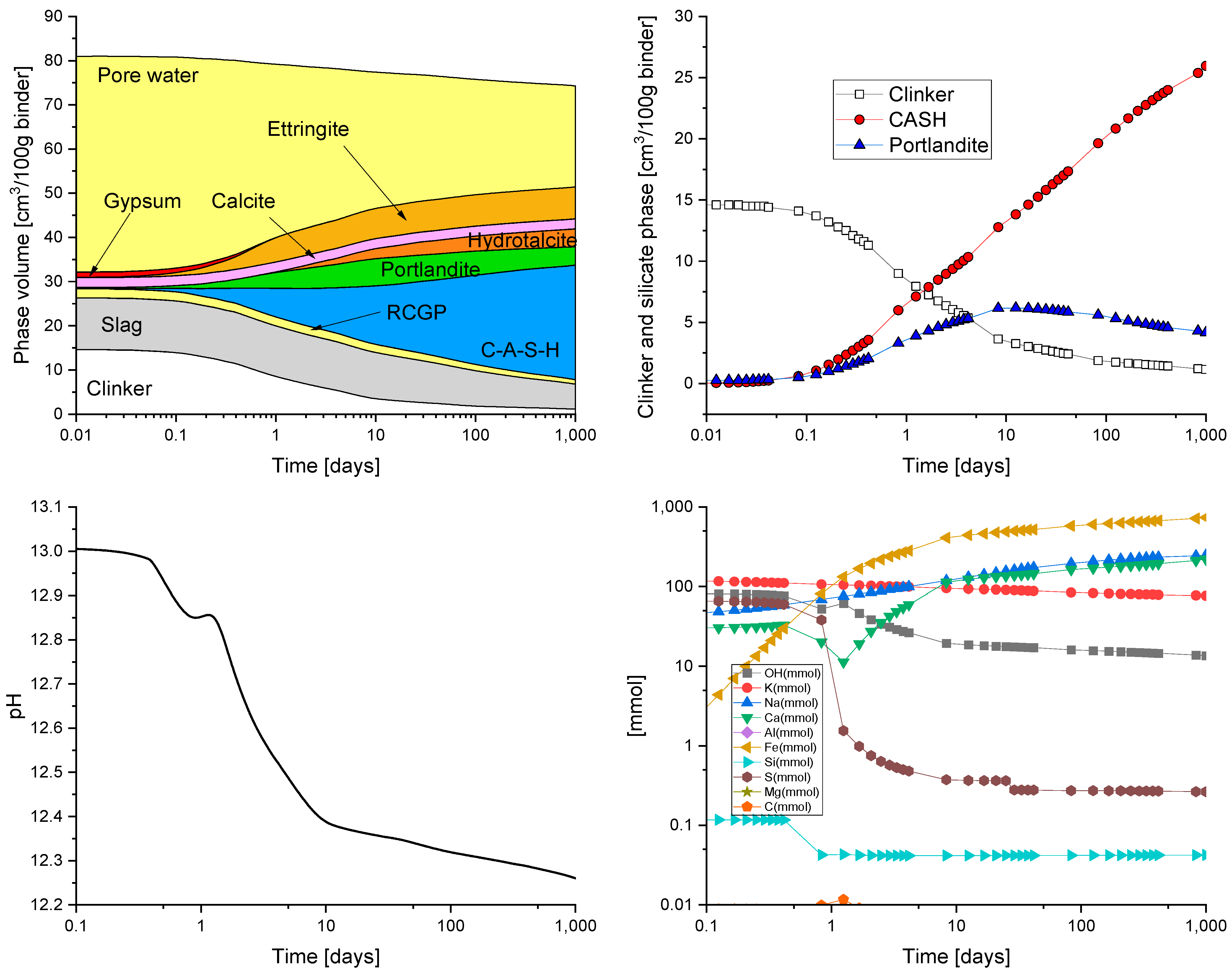
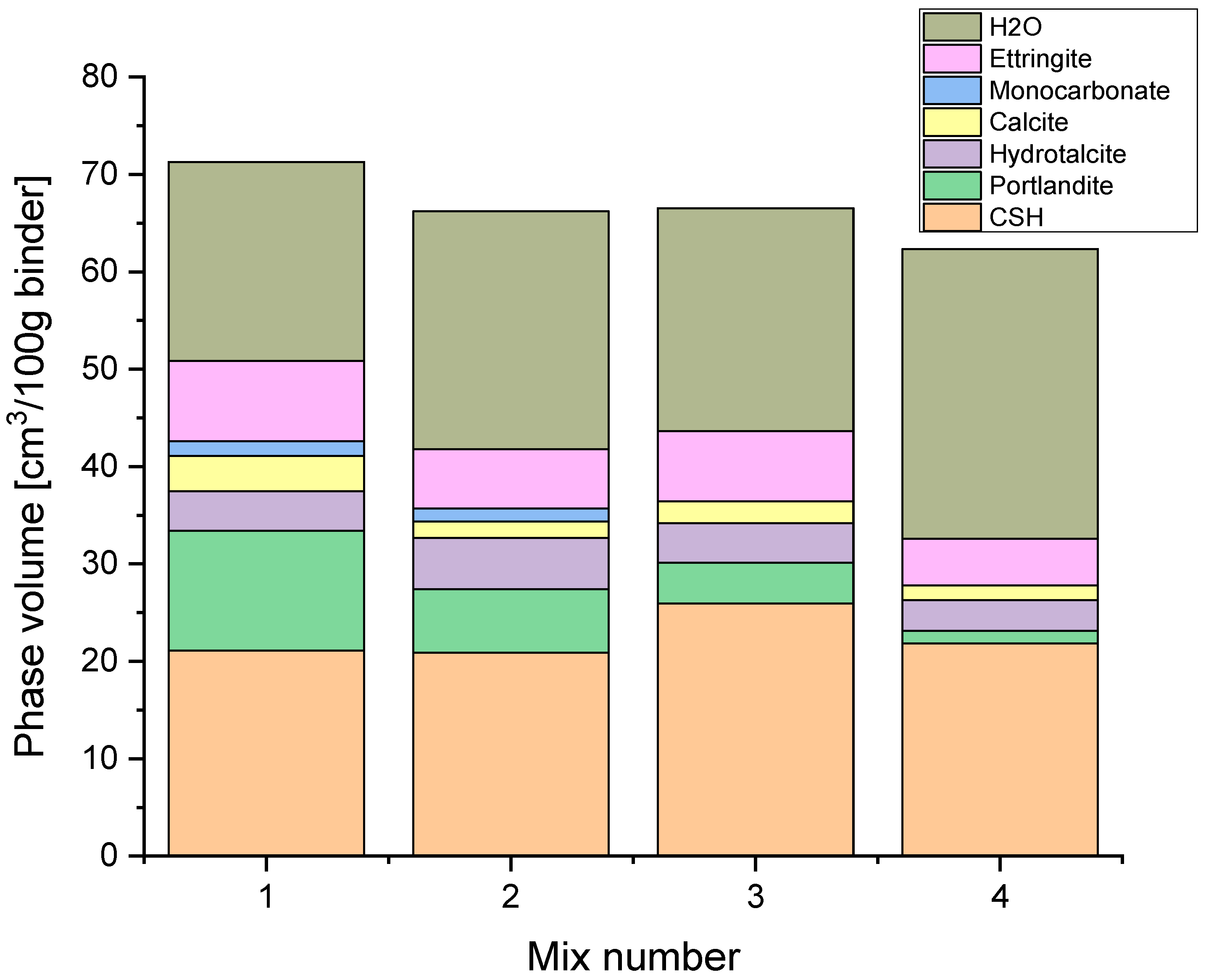
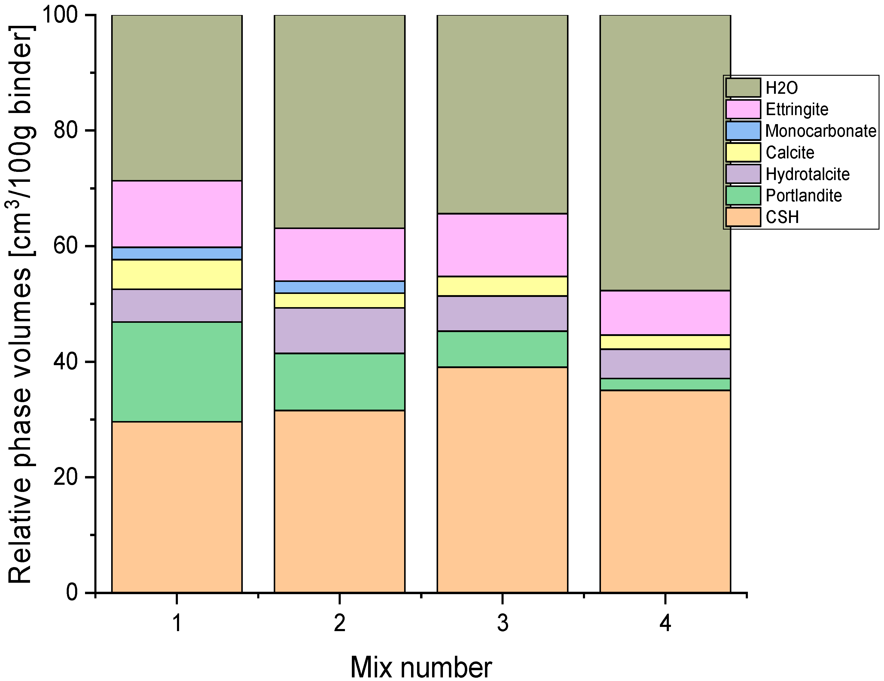
3. Results
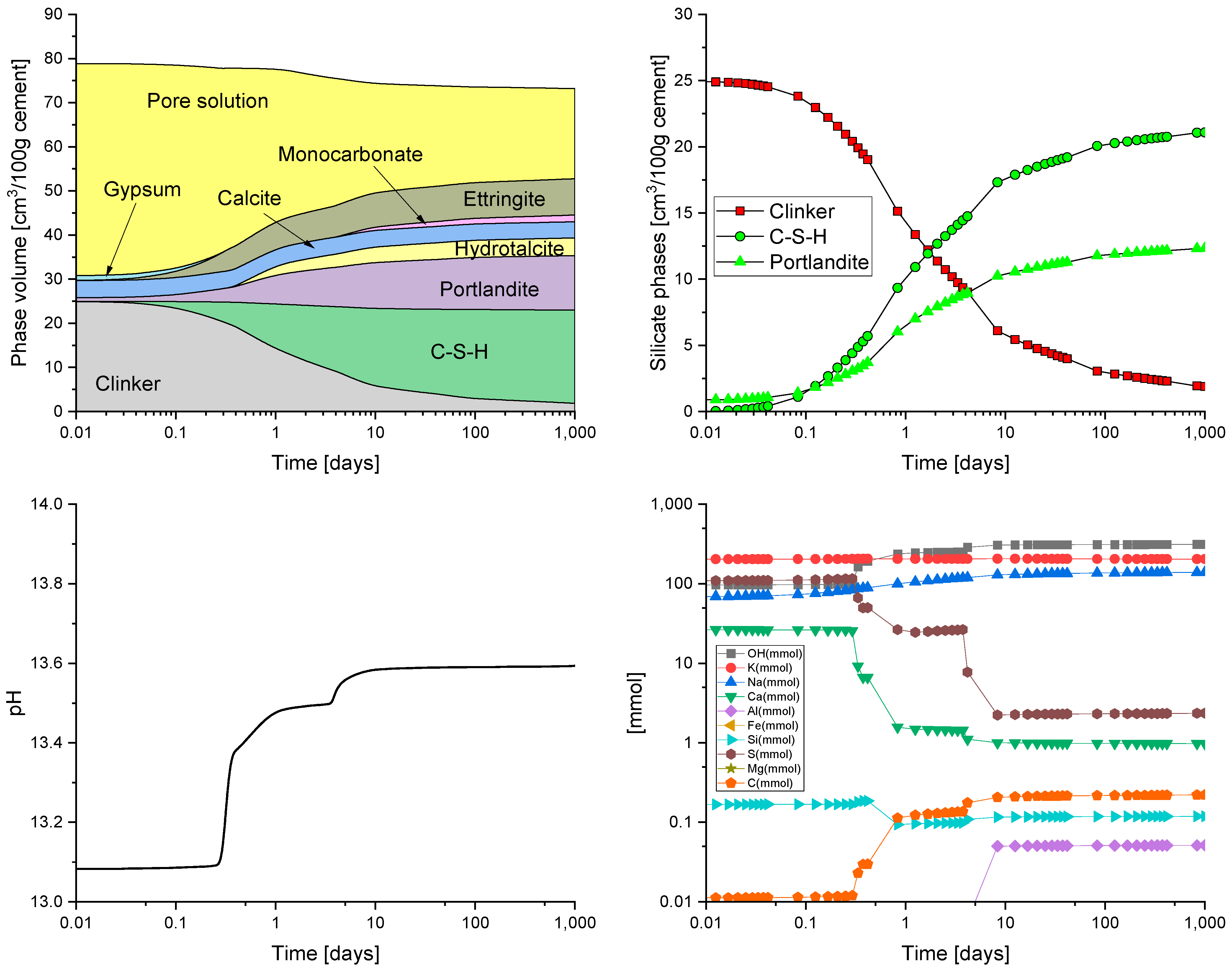
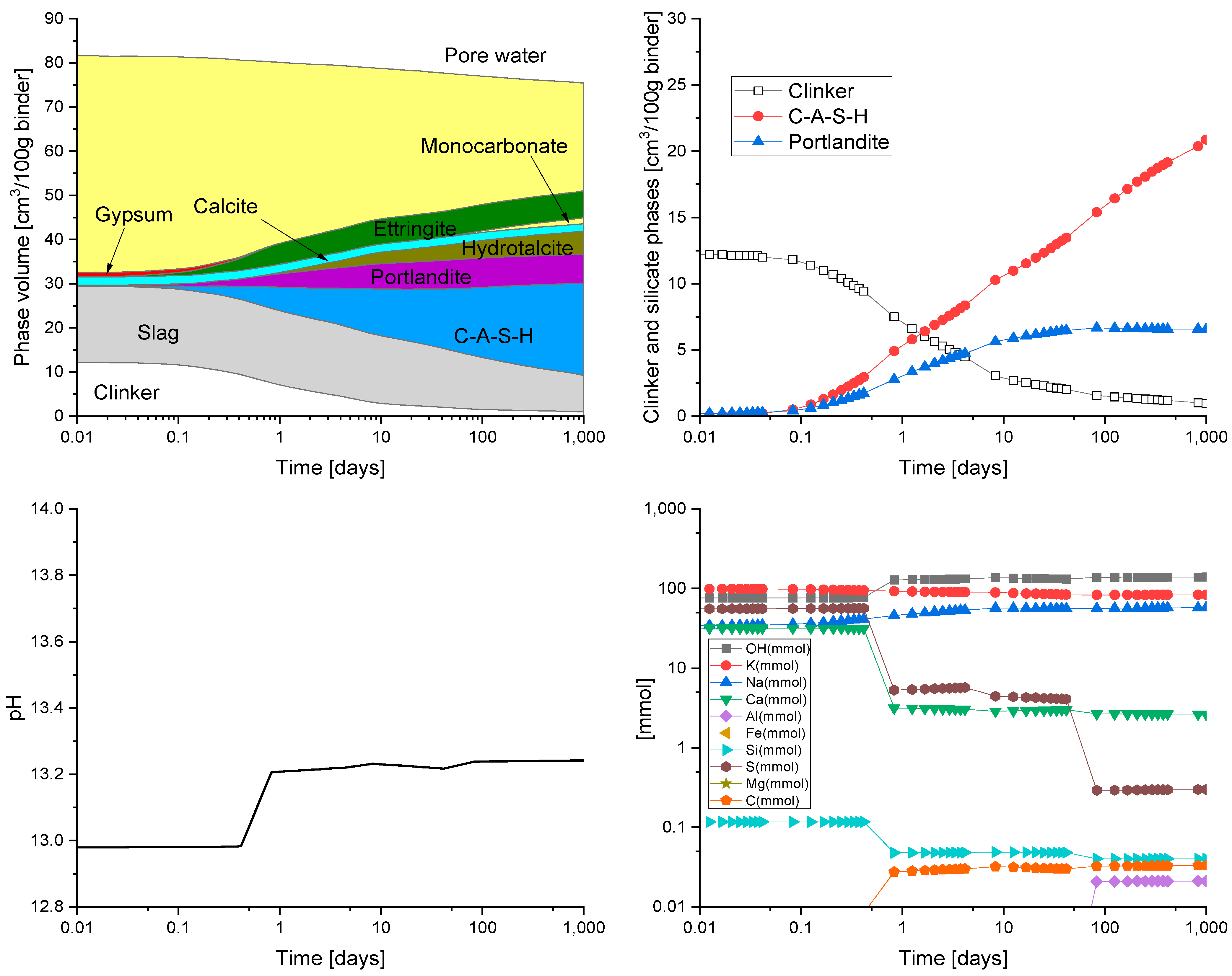
HYDCEM Predictions
4. Discussion
5. Conclusions
Author Contributions
Funding
Data Availability Statement
Conflicts of Interest
Abbreviations
| C-S-H | Calcium-Silica-Hydrate |
| C-A-S-H | Calcium-Aluminium-Silica-Hydrate |
| GGBS | Ground Granulated Blast Furnace Slag |
| RCGP | Recycled Glass Powder |
| SCM | Supplementary Cementitious Materials |
| PFA | Pulverized Fuel Ash |
| CCSU | Carbon Capture, Storage and Use |
| ASR | Alkali–Silica Reaction |
References
- Derobert, E.; Operations Howard Klee, J. World Business Council for Sustainable Development; France IEA Publications: Paris, France, 2002. [Google Scholar]
- Gartner, E. Industrially interesting approaches to “low-CO2” cements. Cem. Concr. Res. 2004, 34, 1489–1498. [Google Scholar] [CrossRef]
- Gartner, E.; Hirao, H. A review of alternative approaches to the reduction of CO2 emissions associated with the manufacture of the binder phase in concrete. Cem. Concr. Res. 2015, 78, 126–142. [Google Scholar] [CrossRef]
- Scrivener, K.L.; John, V.M.; Gartner, E.M. Eco-efficient cements: Potential economically viable solutions for a low-CO2 cement-based materials industry. Cem. Concr. Res. 2018, 114, 2–26. [Google Scholar] [CrossRef]
- Lehne, J.; Preston, F. Making concrete change: Innovation in low-carbon cement and concrete. Chatham House Rep. 2018, 13. Available online: https://www.chathamhouse.org/2018/06/making-concrete-change-innovation-low-carbon-cement-and-concrete (accessed on 30 January 2024).
- Vaitkevičius, V.; Šerelis, E.; Hilbig, H. The effect of glass powder on the microstructure of ultra high performance concrete. Constr. Build. Mater. 2014, 68, 102–109. [Google Scholar] [CrossRef]
- El-Tair, A.; Youssef, P.; El-Nemr, A. Using GLP as Partial Replacement in Cement Mortars. MATEC Web Conf. 2018, 199, 07005. [Google Scholar] [CrossRef]
- Li, Q.; Qiao, H.; Li, A.; Li, G. Performance of waste glass powder as a pozzolanic material in blended cement mortar. Constr. Build. Mater. 2022, 324, 126531. [Google Scholar] [CrossRef]
- Tamanna, N.; Tuladhar, R. Sustainable use of recycled glass powder as cement replacement in concrete. Open Waste Manag. J. 2020, 13, 1–13. [Google Scholar] [CrossRef]
- Nasiru, S.; Jiang, L.; Yu, L.; Chu, H.; Huang, Y.; Pei, C.; Gu, Y.; Jin, W.; Eyram Klu, E.; Guo, M.-Z. Properties of cement mortar containing recycled glass and rice husk ash. Constr. Build. Mater. 2021, 299, 123900. [Google Scholar] [CrossRef]
- Ibrahim, K.I.M. Recycled waste glass powder as a partial replacement of cement in concrete containing silica fume and fly ash. Case Stud. Constr. Mater. 2021, 15, e00630. [Google Scholar] [CrossRef]
- Zhang, X.; Li, D.; Lang, L. Evaluation of strength development in cemented dredged sediment admixing recycled glass powder. Constr. Build. Mater. 2022, 342, 127996. [Google Scholar] [CrossRef]
- Tran, N.P.; Wang, T.; Nguyen, T.N.; Jin, H.; Ngo, T.D. High-volume recycled glass cementitious and geopolymer composites incorporating graphene oxide. Constr. Build. Mater. 2024, 450, 138476. [Google Scholar] [CrossRef]
- Glass, B. Glass Sector Net Zero Strategy 2050; British Glass: Sheffield, UK, 2021. [Google Scholar]
- EPA. EPS Calls for Measures to Urgently Tackle Packaging Waste Generation. Million Tonnes, Plastics Present a Serious Challenge. Available online: https://www.epa.ie/news-releases/news-releases-2023/epa-calls-for-measures-to-urgently-tackle-packaging-waste-generation-.php#:~:text=Ireland (accessed on 30 January 2024).
- British Glass. Recycle It Right. Available online: https://www.britglass.org.uk/our-work/recycling/recycle-it-right (accessed on 30 January 2024).
- Dhir, R.K.; Limbachiya, M.C.; Dyer, T.D. Recycling and Reuse of Glass Cullet; Institution of Civil Engineers: London, UK, 2001; ISBN 0727748971. [Google Scholar]
- Chen, G.; Lee, H.; Young, K.L.; Yue, P.L.; Wong, A.; Tao, T.; Choi, K.K. Glass recycling in cement production—An innovative approach. Waste Manag. 2002, 22, 747–753. [Google Scholar] [CrossRef] [PubMed]
- Idir, R.; Cyr, M.; Tagnit-Hamou, A. Pozzolanic properties of fine and coarse color-mixed glass cullet. Cem. Concr. Compos. 2011, 33, 19–29. [Google Scholar] [CrossRef]
- Ke, G.; Li, W.; Li, R.; Li, Y.; Wang, G. Mitigation effect of waste glass powders on alkali–silica reaction (ASR) expansion in cementitious composite. Int. J. Concr. Struct. Mater. 2018, 12, 1–14. [Google Scholar] [CrossRef]
- BSI—BS PAS 101; Recovered Container Glass Specification for Quality and Guidance for Good Practice in Collection. BSI: Singapore, 2003.
- Holmes, N.; Kelliher, D.; Tyrer, M. HYDCEM: A New Cement Hydration Model. In Proceedings of the 2nd International Conference of Sustainable Building Materials, Eindhoven, The Netherlands, 12–15 August 2019; pp. 66–74. [Google Scholar]
- Holmes, N.; Kelliher, D.; Tyrer, M.; Shaji, N. HYDCEM—A new cement hydration model. In Proceedings of the 42nd Cement and Concrete Science Conference on Novel Developments and Innovation in Cementitious Materials, Imperial College, London, UK, 11–12 September 2023. [Google Scholar]
- Holmes, N.; Tyrer, M.; West, R.P.; Lowe, A.; Kelliher, D. Using PHREEQC to model cement hydration. Constr. Build. Mater. 2022, 319, 126–129. [Google Scholar] [CrossRef]
- Ogoro, E.; Holmes, N.; Kelliher, D.; Tyrer, M. Predicting mortar compressive strength using HYDCEM. In Proceedings of the Civil Engineering Research in Ireland (CERI) Conference, Dublin, Ireland, 27–28 August 2020. [Google Scholar]
- Holmes, N.; Kelliher, D.; Tyrer, M.; Holmes, N.; Kelliher, D.; Tyrer, M. Modelling the Addition of Limestone in Cement using HYDCEM. In Proceedings of the 39th Cement and Concrete Science Conference, Bath, UK, 9–10 September 2019; pp. 23–27. [Google Scholar]
- Holmes, N.; Kelliher, D.; Tyrer, M. Simulating cement hydration using HYDCEM. Constr. Build. Mater. 2020, 239, 117811. [Google Scholar] [CrossRef]
- Parkhust, D.L.; Appelo, C.A.J. A Computer Program for Speciation, Batch-Reaction, One-Dimensional Transport and Inverse Geochemical Calculations; US Geological Survey: Reston, VA, USA, 1999. [Google Scholar]
- Parkhurst, D.J.; Appelo, C.A.J. Description of Input and Examples for PHREEQC Version 3—A Computer Program for Speciation, Batch-Reaction, One-Dimensional Transport and Inverse Geochemical Calculations; U.S. Geological Survey Techniques and Methods: Reston, VA, USA, 2013. [Google Scholar]
- Lothenbach, B.; Kulik, D.A.; Matschei, T.; Balonis, M.; Baquerizo, L.; Dilnesa, B.; Miron, G.D.; Myers, R.J. Cemdata18: A chemical thermodynamic database for hydrated Portland cements and alkali-activated materials. Cem. Concr. Res. 2019, 115, 472–506. [Google Scholar] [CrossRef]
- Czapik, P.; Owsiak, Z.; Zapała-Sławeta, J. Diagnosis of concrete structures distress due to alkali-aggregate reaction. Bull. Polish Acad. Sci. Tech. Sci. 2015, 63, 23–29. [Google Scholar]
- Killoh, L.J.; Parrot, D.C. Prediction of cement hydration. Br. Ceram. Proc. 1984, 35, 41–53. [Google Scholar]
- Kulik, D.A.; Winnefeld, F.; Kulik, A.; Miron, G.D.; Lothenbach, B. CemGEMS—An easy-to-use web application for thermodynamic modelling of cementitious materials. RILEM Tech. Lett. 2021, 6, 36–52. [Google Scholar] [CrossRef]
- Holmes, N.; Tyrer, M. Employing Discrete Solid Phases to represent C-S-H solid solutions in the cemdata07 thermodynamic database to model cement hydration using PHREEQC Geochemical Software. Appl. Sci. 2022, 12, 10039. [Google Scholar] [CrossRef]
- Lothenbach, B.; Le Saout, G.; Gallucci, E.; Scrivener, K. Influence of limestone on the hydration of Portland cements. Cem. Concr. Res. 2008, 38, 848–860. [Google Scholar] [CrossRef]
- Shaji, N.; Holmes, N.; Tyrer, M. Derivation of fly-ash glass phase equations for use in thermodynamic models. In Proceedings of the Civil Engineering Research in Ireland Conference, Galway, Ireland, 29–30 August 2024. [Google Scholar]
- BSI 8500 Concrete; Complementary British Standard to BS EN 206. Specification for Constituent Materials and Concrete. British Standards Institution: London, UK, 2019; p. 52.
- BSI Flex 350; Alternative Binder Systems for Lower Carbon Concrete. British Standards Institution: London, UK, 2024.


| Mix No. | Active/Inert Glass Phase |
|---|---|
| 2 (50% slag) | (SiO2)6.0653(Al2O3)0.9651(Fe2O3)0.0494(CaO)7.8955(MgO)1.9639(SO3)0.0102(K2O)0.0478(Na2O)0.033 = + 6.0653 SiO2 + 1.9302 AlO2− + 0.0988 FeO2− + 7.8955 Ca+2 + 1.9639 Mg+2 + 0.0102 SO4−2 + 0.0956 K+ + 0.066 Na+ − 17.831 H+ + 8.9155 H2O; log_k = ±999, Vm = 401.6064 g/cm3 |
| 3 (34% slag) | (SiO2)6.0702(Al2O3)0.9659(Fe2O3)0.0494(CaO)7.902(MgO)1.9655(K2O)0.0479(Na2O)0.0331 = + 6.0702 SiO2 + 1.9318 AlO2− + 0.0988 FeO2− + 7.902 Ca+2 + 1.9655 Mg+2 + 0.0958 K+ + 0.0662 Na+ − 17.8664 H+ + 8.9332 H2O; log_k = ±999, Vm = 401.6064 g/cm3 |
| 3 (6% RCGP) | (SiO2)12.2273(Al2O3)0.1307(Fe2O3)0.0227(CaO)2.8507(MgO)0.4286(K2O)0.0566(Na2O)1.0634 = + 12.2273 SiO2 + 0.2614 AlO2− + 0.0454 FeO2− + 2.8507 Ca+2 + 0.4286 Mg+2 + 0.1132 K+ + 2.1268 Na+ − 8.4918 H+ + 4.2459 H2O; log_k = ±999, Vm = 401.6064 g/cm3 |
| 3 (51% slag) | (SiO2)6.0702(Al2O3)0.9659(Fe2O3)0.0494(CaO)7.902(MgO)1.9655(K2O)0.0479(Na2O)0.0331 = + 6.0702 SiO2 + 1.9318 AlO2− + 0.0988 FeO2− + 7.902 Ca+2 + 1.9655 Mg+2 + 0.0958 K+ + 0.0662 Na+ - 17.8664 H+ + 8.9332 H2O; log_k = ±999, Vm = 401.6064 g/cm3 |
| 3 (9% RCGP) | (SiO2)12.2273(Al2O3)0.1307(Fe2O3)0.0227(CaO)2.8507(MgO)0.4286(K2O)0.0566(Na2O)1.0634 = + 12.2273 SiO2 + 0.2614 AlO2− + 0.0454 FeO2− + 2.8507 Ca+2 + 0.4286 Mg+2 + 0.1132 K+ + 2.1268 Na+ − 8.4918 H+ + 4.2459 H2O; log_k = ±999, Vm = 401.6064 g/cm3 |
| Composition of Blending Components (Mass%) | Composition of Paste Formulations | |||||
|---|---|---|---|---|---|---|
| Oxide | RCGP | GGBS | CEM II A/L | Control | 40% Blend | 60% Blend |
| SiO2 | 68.89 | 35.59 | 17.98 | 26.79 | 27.02 | 29.28 |
| CaO | 14.99 | 43.24 | 62.45 | 52.86 | 53.07 | 50.73 |
| MgO | 1.62 | 7.73 | 2.57 | 5.15 | 4.267 | 4.69 |
| Al2O3 | 1.25 | 9.61 | 4.14 | 6.88 | 5.83 | 6.25 |
| Fe2O3 | 0.34 | 0.77 | 2.85 | 1.81 | 1.99 | 1.78 |
| TiO2 | 0.08 | 0.66 | 0.33 | 0.50 | 0.43 | 0.45 |
| Mn3O4 | 0.04 | 0.15 | 0.24 | 0.20 | 0.20 | 0.19 |
| Na2O | 6.18 | 0.2 | 0.24 | 0.22 | 0.58 | 0.67 |
| K2O | 0.5 | 0.44 | 0.53 | 0.49 | 0.50 | 0.49 |
| CaCO3 | 0 | 0 | 10.48 | 5.24 | 6.29 | 5.24 |
| Total | 93.89 | 98.39 | 101.81 | 100.14 | 100.18 | 99.77 |
| Mix No. | Proportion of Each Powder (%) | ||
|---|---|---|---|
| CEM II/A-LL | GGBS | RCGP | |
| 1 | 100 | ||
| 2 (control) | 50 | 50 | |
| 3 | 60 | 34 | 6 |
| 4 | 40 | 51 | 9 |
Disclaimer/Publisher’s Note: The statements, opinions and data contained in all publications are solely those of the individual author(s) and contributor(s) and not of MDPI and/or the editor(s). MDPI and/or the editor(s) disclaim responsibility for any injury to people or property resulting from any ideas, methods, instructions or products referred to in the content. |
© 2025 by the authors. Licensee MDPI, Basel, Switzerland. This article is an open access article distributed under the terms and conditions of the Creative Commons Attribution (CC BY) license (https://creativecommons.org/licenses/by/4.0/).
Share and Cite
Tyrer, M.; Richardson, M.; Holmes, N.; Newell, J.; Yio, M.; Wong, H. Predicting the Hydration of Ground Granulated Blast Furnace Slag and Recycled Glass Blended Cements. Appl. Sci. 2025, 15, 6872. https://doi.org/10.3390/app15126872
Tyrer M, Richardson M, Holmes N, Newell J, Yio M, Wong H. Predicting the Hydration of Ground Granulated Blast Furnace Slag and Recycled Glass Blended Cements. Applied Sciences. 2025; 15(12):6872. https://doi.org/10.3390/app15126872
Chicago/Turabian StyleTyrer, Mark, Mark Richardson, Niall Holmes, John Newell, Marcus Yio, and Hong Wong. 2025. "Predicting the Hydration of Ground Granulated Blast Furnace Slag and Recycled Glass Blended Cements" Applied Sciences 15, no. 12: 6872. https://doi.org/10.3390/app15126872
APA StyleTyrer, M., Richardson, M., Holmes, N., Newell, J., Yio, M., & Wong, H. (2025). Predicting the Hydration of Ground Granulated Blast Furnace Slag and Recycled Glass Blended Cements. Applied Sciences, 15(12), 6872. https://doi.org/10.3390/app15126872