

Switching Control of Planar PPR Underactuated Robot with External Interference and Non-Zero Initial Velocity


Abstract
1. Introduction
2. System Model and Analysis
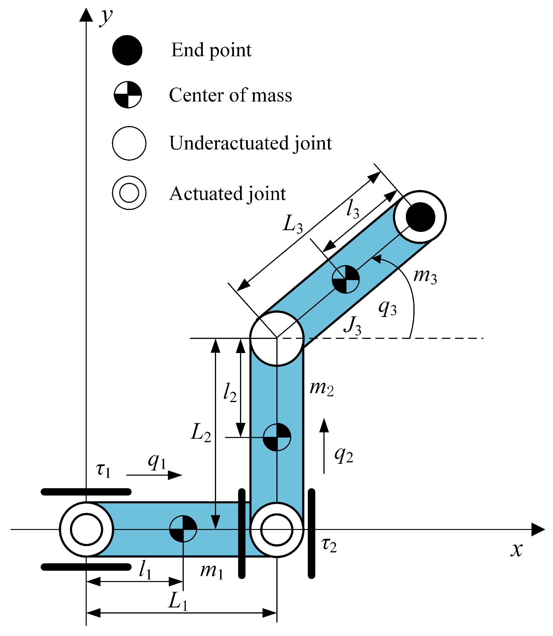
2.1. Dynamic Model
- (1)
- In terms of dynamic equations, the dynamic equation of the planar PPR underactuated robot is established based on the Euler–Lagrange equation. The inertia matrix is a nonlinear function of the generalized coordinate q, and the Coriolis force and centrifugal force terms are nonlinear functions of the generalized coordinates q and .
- (2)
- In terms of kinematics, the kinematics of the planar PPR underactuated robot are described by the homogeneous transformation matrix from the base coordinate system to the end-effector coordinate system. The trigonometric functions containing the joint angle in the homogeneous transformation matrix indicate that there is a nonlinear mapping relationship between the position and attitude of the end effector and the joint angle.
- (3)
- In terms of the relationship between control input and system response, the planar PPR underactuated robot has a non-minimum phase characteristic. This non-minimum phase characteristic leads to a complex nonlinear relationship between control input and system response. Furthermore, the actuators of underactuated robot systems usually have nonlinear characteristics, such as saturation and dead zones.
2.2. Analysis of Model Characteristics
- (1)
- The gravitational component within the dynamic constraint of the underactuated joint remains invariant;
- (2)
- Underactuated joint variables are absent from the inertia matrix.
2.3. Control Method
3. The First-Phase Control
4. The Second-Phase Control
4.1. Model Reduction
4.2. Design of Controller
5. Simulation
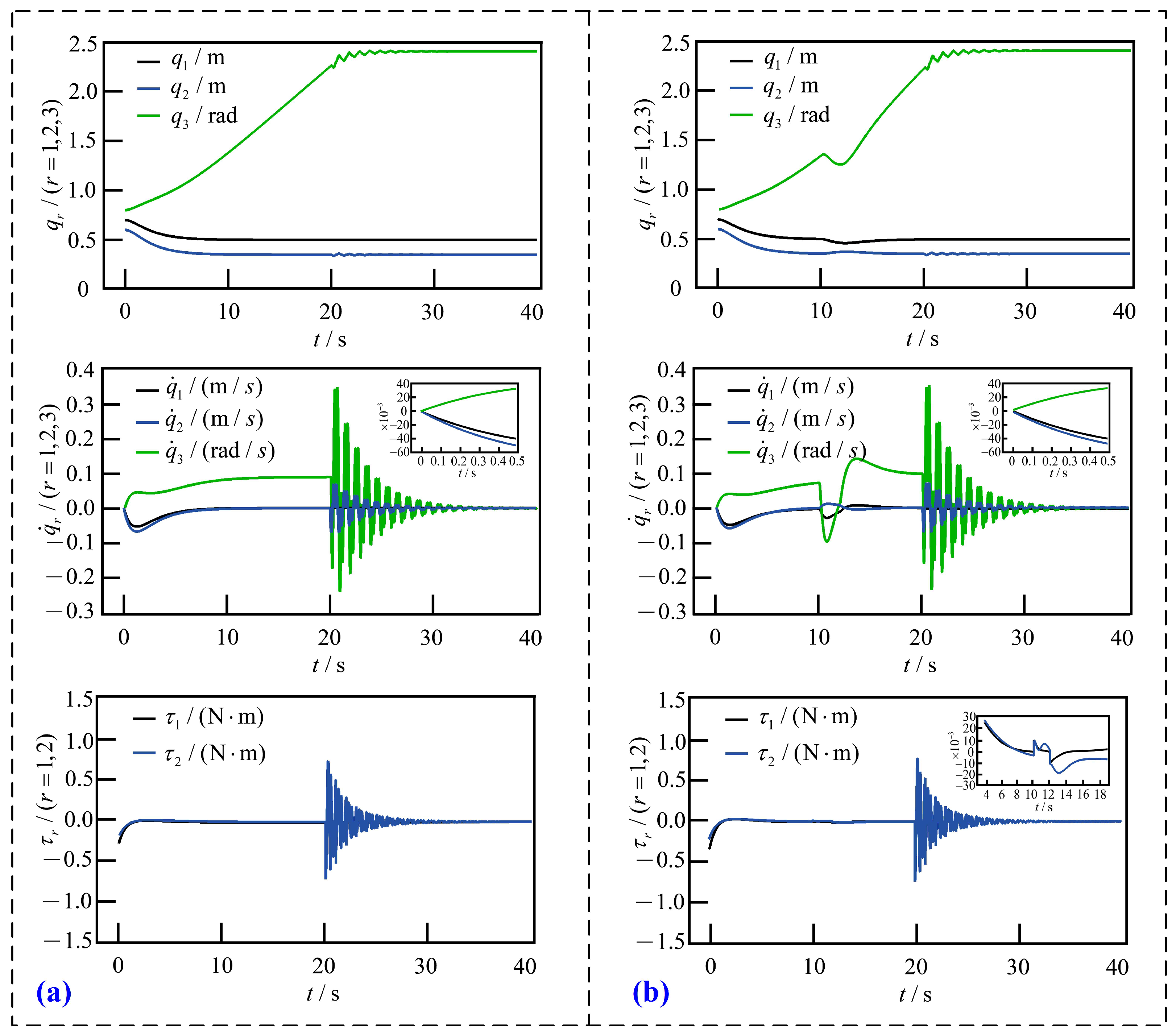
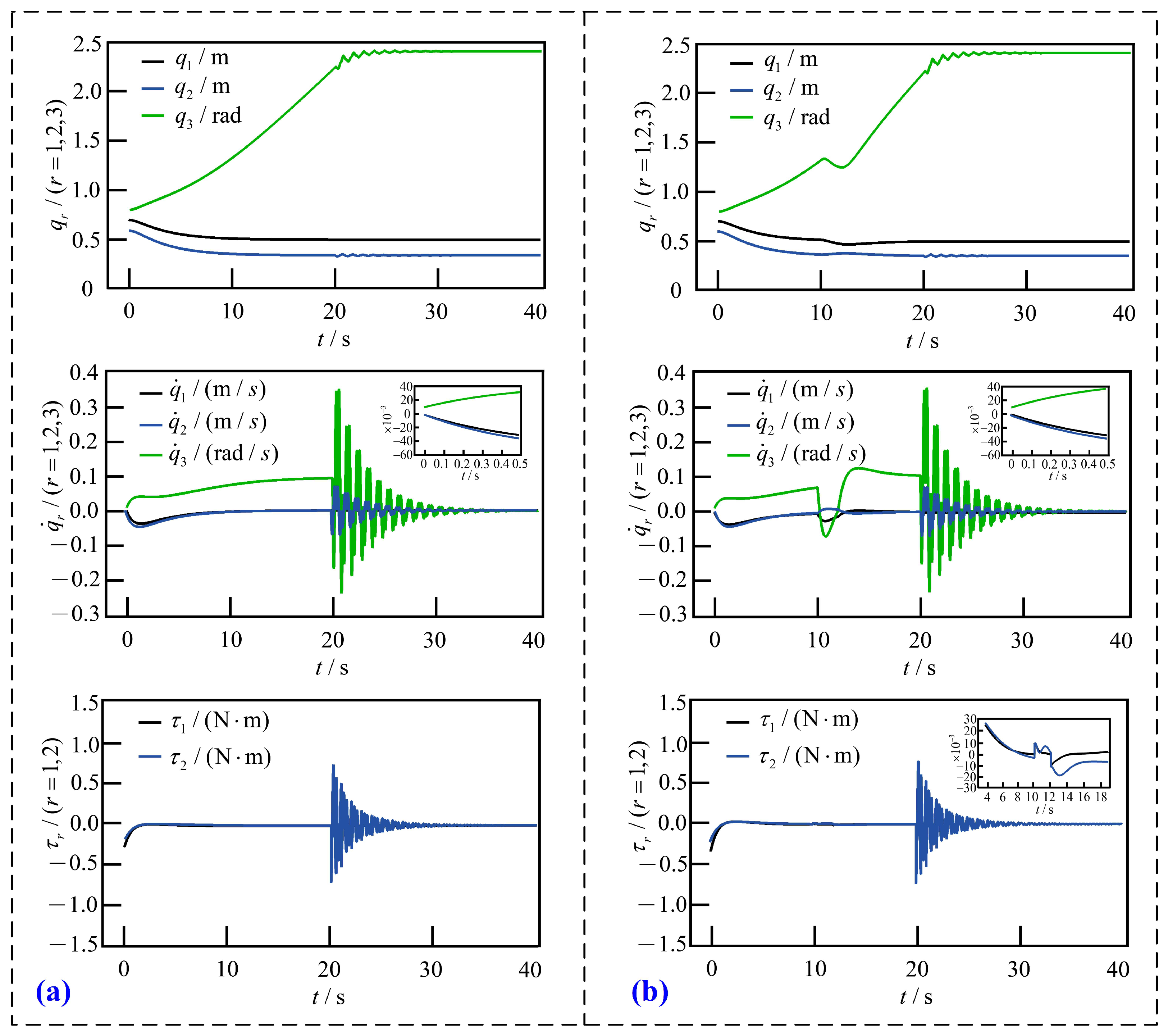
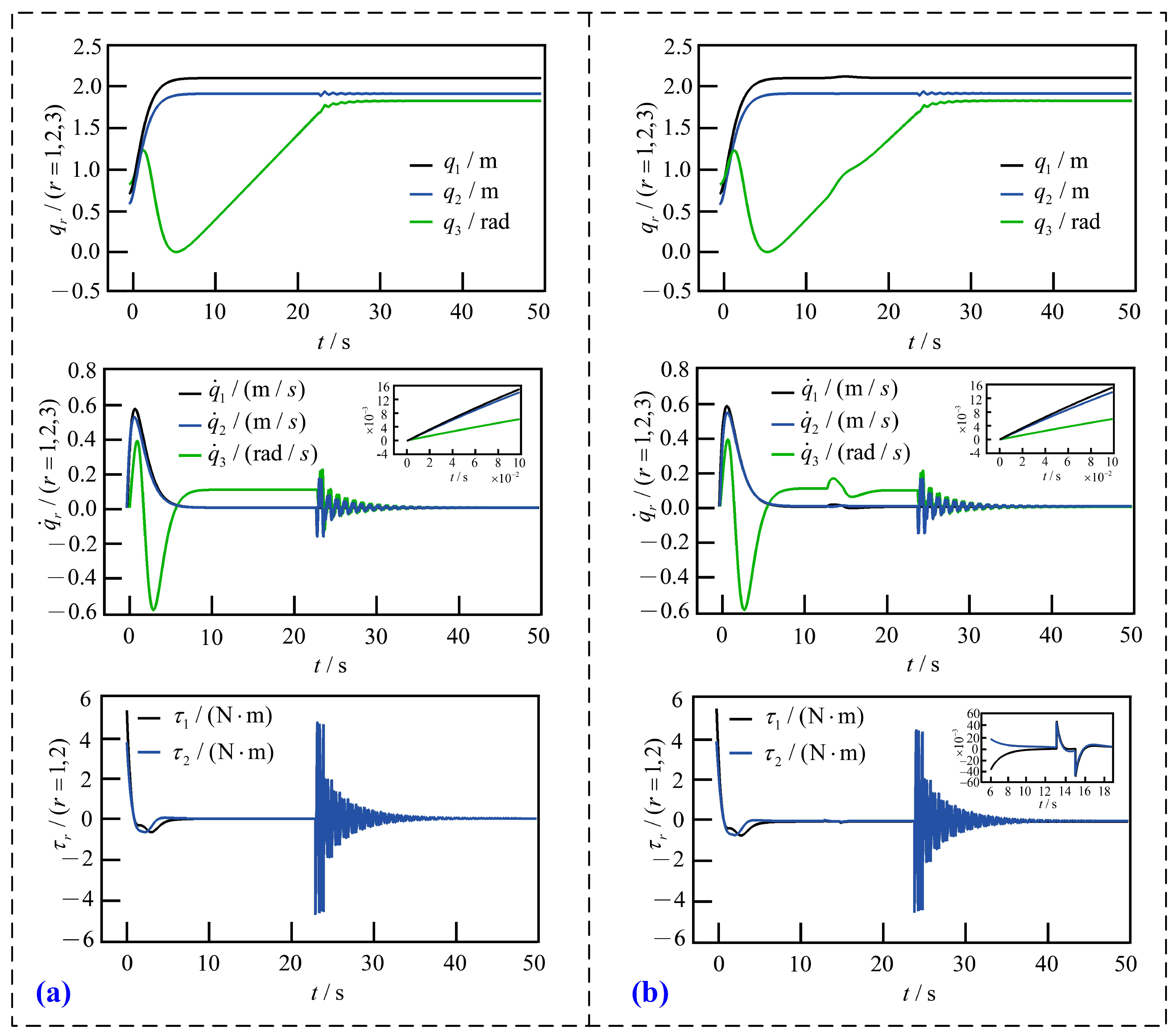
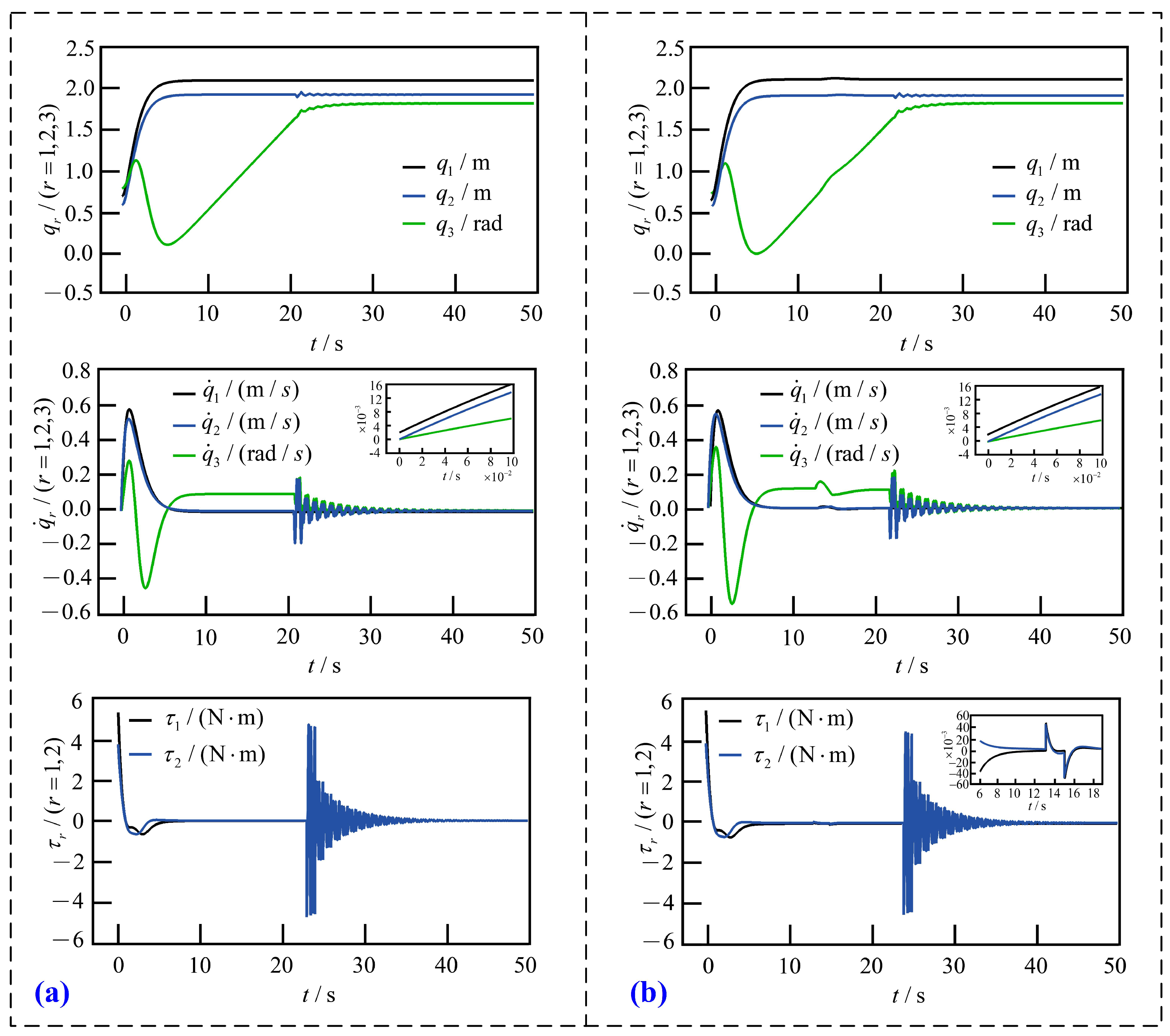
5.1. Case 1
5.2. Case 2
5.3. Comparison and Analysis
6. Conclusions
Author Contributions
Funding
Institutional Review Board Statement
Informed Consent Statement
Data Availability Statement
Conflicts of Interest
References
- Peta, K.; Wiśniewski, M.; Kotarski, M.; Ciszak, O. Comparison of single-arm and dual-arm collaborative robots in precision assembly. Appl. Sci. 2025, 15, 2976. [Google Scholar] [CrossRef]
- Zhou, Z.; Liu, J.; Yu, J. A survey of underwater multi-robot systems. IEEE/CAA J. Autom. Sin. 2022, 9, 1–18. [Google Scholar] [CrossRef]
- Shao, X.; Yao, W.; Li, X.; Sun, G.; Wu, L. Direct trajectory optimization of free-floating space manipulator for reducing spacecraft variation. IEEE Robot. Autom. Lett. 2022, 7, 2795–2802. [Google Scholar] [CrossRef]
- Pham, D.A.; Ahn, J.K.; Han, S.H. Application of improved sliding mode and artificial neural networks in robot control. Appl. Sci. 2024, 14, 5304. [Google Scholar] [CrossRef]
- Zhu, S.; Cheng, G.; Guo, F.; Pang, Y. Dynamic modeling and response analysis of an optical machining robot with prismatic joint clearance. Appl. Sci. 2025, 15, 3197. [Google Scholar] [CrossRef]
- Sompur, V.; Skm, V.; Thondiyath, A. Mission: Dexterous functionality—Redesigning the palmar configuration paradigm of underactuated prosthetic hands. Appl. Sci. 2025, 15, 3214. [Google Scholar] [CrossRef]
- Yang, T.; Sun, N.; Chen, H.; Fang, Y.C. Adaptive optimal motion control of uncertain underactuated mechatronic systems with actuator constraints. IEEE/ASME Trans. Mech. 2023, 28, 210–222. [Google Scholar] [CrossRef]
- Yang, T.; Sun, N.; Fang, Y.C. Neuroadaptive control for complicated underactuated systems with simultaneous output and velocity constraints exerted on both actuated and unactuated states. IEEE Trans. Neural Netw. Learn. Syst. 2023, 34, 4488–4498. [Google Scholar] [CrossRef]
- Harandi, M.R.J.; Khalilpour, S.A.; Taghirad, H.D. Adaptive energy shaping control of a 3-DOF underactuated cable-driven parallel robot. IEEE Trans. Ind. Inf. 2023, 19, 7552–7560. [Google Scholar] [CrossRef]
- Han, F.; Yi, J. Stable learning-based tracking control of underactuated balance robots. IEEE Trans. Robot. Autom. Lett. 2021, 6, 1543–1550. [Google Scholar] [CrossRef]
- Xu, H.; Zhang, K.; Zhang, D.; Zheng, Q. Traffic-responsive control technique for fully-actuated coordinated signals. IEEE Trans. Intell. Transp. Syst. 2022, 23, 5460–5469. [Google Scholar] [CrossRef]
- Zhu, L.C.; Zhang, L.L.; Cheng, Q.; Hua, C.C. Multi-variable constrained control for uncertain high-order strict-feedback fully actuated nonlinear systems. J. Frankl. Inst. 2024, 361, 107190. [Google Scholar] [CrossRef]
- Ma, Y.H.; Zhang, K.; Jaing, B. Practical prescribed-time active fault-tolerant control for mixed-order heterogeneous multiagent systems: A fully actuated system approach. Automatica 2024, 166, 111721. [Google Scholar] [CrossRef]
- Lai, C.L.; Lin, X.G.; Su, Z.Y.; Zhao, D.W. Event-triggered coordinated trajectory tracking control for multiple fully-actuated MSVs under prescribed performance constraints and limited transmission resources. Ocean Eng. 2023, 281, 114529. [Google Scholar] [CrossRef]
- Heinen, Y.; Tanev, I.; Kimura, T. The effect of a limited underactuated posterior joint on the speed and energy efficiency of a fish robot. Appl. Sci. 2024, 14, 5010. [Google Scholar] [CrossRef]
- Yang, T.; Chen, H.; Sun, N.; Fang, Y.C. Adaptive neural network output feedback control of uncertain underactuated systems with actuated and unactuated state constraints. IEEE Trans. Syst. Man Cybern. Syst. 2022, 52, 7027–7043. [Google Scholar] [CrossRef]
- Degorre, L.; Fossen, T.I.; Chocron, O. A model-based kinematic guidance method for control of underactuated autonomous underwater vehicles. Control Eng. Pract. 2024, 152, 106068. [Google Scholar] [CrossRef]
- Lu, B.; Fang, Y. Online trajectory planning control for a class of underactuated mechanical systems. IEEE Trans. Autom. Control 2024, 69, 442–448. [Google Scholar] [CrossRef]
- Yang, T.; Sun, N.; Fang, Y.C. Adaptive fuzzy control for a class of MIMO underactuated systems with plant uncertainties and actuator deadzones: Design and experiments. IEEE Trans. Cybern. 2022, 52, 8213–8226. [Google Scholar] [CrossRef]
- Zhai, M.; Sun, N.; Yang, T.; Fang, Y.C. Underactuated mechanical systems with both actuator and actuated/unactuated state constraints: A predictive control-based approach. IEEE/ASME Trans. Mechatron. 2023, 28, 1359–1371. [Google Scholar] [CrossRef]
- Alaci, S.; Ciornei, F.C.; Suciu, C.C.; Romanu, I.C. The effect of structural aspect for planar systems with 2DOF upon the stability of motion. IOP Conf. Ser. Mater. Sci. Eng. 2021, 1169, 12003–12010. [Google Scholar] [CrossRef]
- Rapp, P.; Sawodny, O.; Tarín, C. An immersion and invariance based speed and rotation angle observer for a class of revolute/prismatic manipulators with two degrees of freedom. In Proceedings of the 52nd IEEE Conference on Decision and Control, Firenze, Italy, 10–13 December 2013; pp. 6365–6371. [Google Scholar] [CrossRef]
- Wu, L.C.; Kuai, X.K.; Yang, G.S. Nonholonomic control of a planar prismatic-revolute underactuated manipulator. In Proceedings of the 2013 Science and Information Conference, London, UK, 7–9 October 2013; pp. 144–147. [Google Scholar]
- Reni Prasad, A.X.; Ganesh, M.; Kumar, R.H. Analysis of actuation schemes for 3-PPRS parallel manipulator. In Proceedings of the 2022 Third International Conference on Intelligent Computing Instrumentation and Control Technologies (ICICICT), Kannur, India, 11–12 August 2022; pp. 430–435. [Google Scholar] [CrossRef]
- Ichida, K.; Watanabe, K.; Izumi, K. Control of three-link underactuated manipulators by a logic-based switching method. In Proceedings of the 2009 International Conference on Networking, Sensing and Control, Okayama, Japan, 26–29 March 2009; pp. 108–112. [Google Scholar] [CrossRef]
- Reyhanoglu, M.; Cho, S.; McClamroch, N.H. Feedback control of a planar manipulator with an unactuated elastically mounted end effector. In Proceedings of the 1999 IEEE International Conference on Robotics and Automation, Detroit, MI, USA, 10–15 May 1999; pp. 2805–2810. [Google Scholar] [CrossRef]
- Fantoni, I. Stabilization of a planar prismatic-prismatic-revolute manipulator based on an energy approach. In Proceedings of the 40th IEEE Conference on Decision and Control (Cat. No. 01CH37228), Orlando, FL, USA, 4–7 December 2001; pp. 3752–3757. [Google Scholar] [CrossRef]
- Wu, L.C.; Yang, G.S.; Sun, Z.Q. A tracking control method for a PPR underactuated manipulator. In Proceedings of the International Conference on Control, Automation and Systems, Goyang-si, Republic of Korea, 27–30 October 2010; pp. 1255–1258. [Google Scholar] [CrossRef]
- Lai, X.Z.; Wang, Y.W.; Wu, M.; Cao, W.H. Stable control strategy for planar three-link underactuated mechanical system. IEEE/ASME Trans. Mech. 2016, 21, 1345–1356. [Google Scholar] [CrossRef]
- LaSalle, J.P. Stability theory for ordinary differential equations. J. Differ. Equ. 1968, 4, 57–65. [Google Scholar] [CrossRef]
- De Luca, A.; Iannitti, S.; Mattone, R.; Oriolo, G. Control problems in underactuated manipulators. In Proceedings of the 2001 IEEE/ASME International Conference on Advanced Intelligent Mechatronics, Como, Italy, 8–11 July 2001; pp. 855–861. [Google Scholar]
- Huang, Z.X.; Wei, S.Q.; Chen, Z.; Wang, L.J. Iterative contraction stability control strategy for planar Prismatic-Rotational underactuated robot. IEEE Access 2023, 11, 55947–55953. [Google Scholar] [CrossRef]


| Symbol | Significance | Unit |
|---|---|---|
| The mass | kg | |
| The length of link | m | |
| The displacement | m | |
| The angle | rad | |
| The moment of inertia | ||
| The distance from joint to center of mass | m | |
| The torque |
| Link r | ||||
|---|---|---|---|---|
| r = 1 | 1 | 1 | 0.5 | 0 |
| r = 2 | 1 | 1 | 0.5 | 0 |
| r = 3 | 0.5 | 0.5 | 0.25 | 1 |
| Simulation i | Initial Velocity | Interference | Stable Time |
|---|---|---|---|
| 1 | 0 | 0 | |
| 2 | 0 | ||
| 3 | 0 | ||
| 4 |
| Simulation i | Initial Velocity | Interference | Stable Time |
|---|---|---|---|
| 1 | 0 | 0 | |
| 2 | 0 | ||
| 3 | 0 | ||
| 4 |
| PR Underactuated Robot | PPR Underactuated Robot | |
|---|---|---|
| Phase 1 control | Sliding mode control | Improved PD control |
| Phase 2 control | Iterative shrinkage | Iterative shrinkage |
| Stable time | 40–50 | 35–45 |
| Initial velocity | — | Quick response |
| Torque interference | — | Effective resistance |
Disclaimer/Publisher’s Note: The statements, opinions and data contained in all publications are solely those of the individual author(s) and contributor(s) and not of MDPI and/or the editor(s). MDPI and/or the editor(s) disclaim responsibility for any injury to people or property resulting from any ideas, methods, instructions or products referred to in the content. |
© 2025 by the authors. Licensee MDPI, Basel, Switzerland. This article is an open access article distributed under the terms and conditions of the Creative Commons Attribution (CC BY) license (https://creativecommons.org/licenses/by/4.0/).
Share and Cite
Huang, Z.; Gong, X.; Lei, Q.; Zhou, H. Switching Control of Planar PPR Underactuated Robot with External Interference and Non-Zero Initial Velocity. Appl. Sci. 2025, 15, 6601. https://doi.org/10.3390/app15126601
Huang Z, Gong X, Lei Q, Zhou H. Switching Control of Planar PPR Underactuated Robot with External Interference and Non-Zero Initial Velocity. Applied Sciences. 2025; 15(12):6601. https://doi.org/10.3390/app15126601
Chicago/Turabian StyleHuang, Zixin, Xiangyu Gong, Qian Lei, and Hongjian Zhou. 2025. "Switching Control of Planar PPR Underactuated Robot with External Interference and Non-Zero Initial Velocity" Applied Sciences 15, no. 12: 6601. https://doi.org/10.3390/app15126601
APA StyleHuang, Z., Gong, X., Lei, Q., & Zhou, H. (2025). Switching Control of Planar PPR Underactuated Robot with External Interference and Non-Zero Initial Velocity. Applied Sciences, 15(12), 6601. https://doi.org/10.3390/app15126601