
Non-Carbon-Supported, Pt-Based Catalysts with Applications in the Electrochemical Hydrogen Pump/Compressor (EHP/C)

Abstract
1. Introduction
2. Materials and Methods
2.1. Catalyst’s Synthesis
2.2. Physicochemical Characterization
2.3. Electrode and MEA Preparation
2.4. Electrochemical Testing
2.5. Artificial Intelligence Tools
3. Results
4. Conclusions
Author Contributions
Funding
Institutional Review Board Statement
Informed Consent Statement
Data Availability Statement
Acknowledgments
Conflicts of Interest
References
- Boretti, A.; Pollet, B.G. Hydrogen economy: Paving the path to a sustainable, low-carbon future. Int. J. Hydrogen Energy 2024, 93, 307–319. [Google Scholar] [CrossRef]
- Barreto, L.; Makihira, A.; Riahi, K. The hydrogen economy in the 21st century: A sustainable development scenario. Int. J. Hydrogen Energy 2003, 28, 267–284. [Google Scholar] [CrossRef]
- Riahi, K.; Roehrl, R.A.; Schrattenholzer, L.; Miketa, A. Technology clusters in sustainable development scenarios. Prog. Rep. Environ. Issue Groups 2001, 112–120. [Google Scholar]
- Hydrogenics 1 MW PEM electrolyser for European consortium. Fuel Cells Bull. 2015, 2015, 9. [CrossRef]
- El-Hamalawy, A.F.; Farag, H.E.Z.; Asif, A. Multi-objective optimal modular design of PEM electrolyzers for efficient and scalable green hydrogen production plants. J. Power Sources 2025, 637, 236510. [Google Scholar] [CrossRef]
- Evro, S.; Oni, B.A.; Tomomewo, O.S. Carbon neutrality and hydrogen energy systems. Int. J. Hydrogen Energy 2024, 78, 1449–1467. [Google Scholar] [CrossRef]
- Shaterabadi, M.; Sadeghi, S.; Jirdehi, M.A. The role of green hydrogen in achieving low and net-zero carbon emissions: Climate change and global warming. In Green Hydrogen in Power Systems; Vahidinasab, V., Mohammadi-Ivatloo, B., Lim, J.S., Eds.; Springer: Cham, Switzerland, 2024; pp. 141–153. [Google Scholar]
- Tian, X.; An, C.; Chen, Z. The role of clean energy in achieving decarbonization of electricity generation, transportation, and heating sectors by 2050: A meta-analysis review. Renew. Sustain. Energy Rev. 2023, 182, 113404. [Google Scholar] [CrossRef]
- Hassan, Q.; Algburi, S.; Sameen, A.Z.; Jaszczur, M.; Salman, H.M. Hydrogen as an energy carrier: Properties, storage methods, challenges, and future implications. Environ. Syst. Decis. 2024, 44, 327–350. [Google Scholar] [CrossRef]
- Le, T.T.; Sharma, P.; Bora, B.J.; Tran, V.D.; Truong, T.H.; Le, H.C.; Nguyen, P.Q.P. Fueling the future: A comprehensive review of hydrogen energy systems and their challenges. Int. J. Hydrogen Energy 2024, 54, 791–816. [Google Scholar] [CrossRef]
- Wells, C.; Minunno, R.; Chong, H.-Y.; Morrison, G.M. Strategies for the adoption of hydrogen-based energy storage systems: An exploratory study in Australia. Energies 2022, 15, 6015. [Google Scholar] [CrossRef]
- Wang, Y.; Qi, Q.; Xiong, W.; Peng, X. Experimental investigation on the hydraulic-driven piston compressor for hydrogen under varied operating conditions. Int. J. Hydrogen Energy 2024, 74, 78–88. [Google Scholar] [CrossRef]
- Platzer, M.F.; Sarigul-Klijn, N. Hydrogen compression technology. In The Green Energy Ship Concept; Springer: Cham, Switzerland, 2021. [Google Scholar]
- Marciuš, D.; Kovač, A.; Firak, M. Electrochemical hydrogen compressor: Recent progress and challenges. Int. J. Hydrogen Energy 2022, 47, 24179–24193. [Google Scholar] [CrossRef]
- Durmus, G.N.B.; Colpan, C.O.; Devrim, Y. A review on the development of the electrochemical hydrogen compressors. J. Power Sources 2021, 494, 229743. [Google Scholar] [CrossRef]
- Rochlitz, L.; Steinberger, M.; Oechsner, R.; Weber, A.; Schmitz, S.; Schillinger, K.; Wolff, M.; Bayler, A. Second use or recycling of hydrogen waste gas from the semiconductor industry—Economic analysis and technical demonstration of possible pathways. Int. J. Hydrogen Energy 2019, 44, 17168–17184. [Google Scholar] [CrossRef]
- Ivanov, B.V.; Mensharapov, R.M.; Ivanova, N.A.; Spasov, D.D.; Sinyakov, M.V.; Grigoriev, S.A.; Fateev, V.N. Experimental study of the electrochemical hydrogen pump based on proton exchange membrane for the application in fusion fuel cycle. Process Saf. Environ. Prot. 2023, 180, 744–751. [Google Scholar] [CrossRef]
- Marciuš, D. The concept of electrochemical hydrogen compression and purification technology. In Challenges and Solutions in the Hydrogen Value Chain; Kovač, A., Ed.; Springer: Cham, Switzerland, 2024. [Google Scholar]
- Huang, F.; Pingitore, A.T.; Benicewicz, B.C. Electrochemical hydrogen separation from reformate using high-temperature polybenzimidazole (PBI) membranes: The role of chemistry. ACS Sustain. Chem. Eng. 2020, 8, 6234–6242. [Google Scholar] [CrossRef]
- Rhandi, M.; Trégaro, M.; Druart, F.; Deseure, J.; Chatenet, M. Electrochemical hydrogen compression and purification versus competing technologies: Part I. Pros and cons. Chin. J. Catal. 2020, 41, 756–769. [Google Scholar] [CrossRef]
- Gasparotto, G.; Chavhan, F.R.; Sgroi, M.F.; Recham, N.; Ventura, L.; Cavani, F.; Barbato, A.; Rozie, H.; Bertei, A. Energy and exergy analysis of hydrogen purification processes: A thermodynamic approach. Chem. Eng. Process. Process Intensif. 2021, 167, 108498. [Google Scholar]
- Trégaro, M.; Druart, F.; Chatenet, M.; Deseure, J. Electrochemical hydrogen purification and compression: Towards an energy-efficient, high-purity hydrogen production process. Int. J. Hydrogen Energy 2022, 47, 25050–25063. [Google Scholar]
- Alrwashdeh, S.S.; Obeidat, K.A. Review of hydrogen purification methods. Int. J. Hydrogen Energy 2023, 48, 15582–15599. [Google Scholar]
- Kang, D.; Jung, J.; Kim, Y. Hydrogen compression using electrochemical hydrogen pump with a solid polymer electrolyte. J. Power Sources 2008, 178, 163–168. [Google Scholar]
- Wang, L.; Liu, H.; Liu, S.; Song, Y. A review of recent developments in electrochemical hydrogen compressors. Renew. Sustain. Energy Rev. 2021, 151, 111618. [Google Scholar]
- Larminie, J.; Dicks, A. Fuel Cell Systems Explained, 2nd ed.; John Wiley & Sons: Chichester, UK, 2003. [Google Scholar]
- Skibina, L.; Kirillov, A.; Grigoriev, S.; Fateev, V. Optimization of electrochemical hydrogen compressor for low-temperature operation. Int. J. Hydrogen Energy 2020, 45, 12943–12950. [Google Scholar]
- Skibina, L.Y.; Grigoriev, S.A.; Fateev, V.N. The use of membrane–electrode assemblies in the electrochemical hydrogen compressor. Int. J. Hydrogen Energy 2019, 44, 14483–14490. [Google Scholar]
- Dickinson, E.J.F.; Wain, A.J.; Unwin, P.R. The hydrogen oxidation reaction on platinum: New insights into the kinetics and mechanism. J. Electroanal. Chem. 2021, 896, 115402. [Google Scholar]
- Ali, M.; Yamada, Y.; Umeda, M. Development of hydrogen pump using proton-conducting polymer electrolyte membrane. Electrochim. Acta 2007, 53, 245–252. [Google Scholar]
- Gaikwad, P.D.; Gupta, R.; Moholkar, V.S. Hybrid electrochemical–membrane process for hydrogen purification from reformate gas. Int. J. Hydrogen Energy 2022, 47, 21227–21243. [Google Scholar]
- Raygan, S.; Seraj, S.; Gharavi, M.J.; Sabetghadam, A. Electrochemical hydrogen pumping using proton-conducting membrane: Modeling and simulation. Int. J. Hydrogen Energy 2023, 48, 4128–4140. [Google Scholar]
- Mayer, K.; Riegel, F.; Heise, M. PEM electrochemical hydrogen compressor system with hydride buffer storage. Int. J. Hydrogen Energy 2020, 45, 7758–7767. [Google Scholar]
- Luo, W.; Takanabe, K. Role of pressure in electrochemical hydrogen compression using PEM electrolyzers. ACS Sustain. Chem. Eng. 2017, 5, 1712–1719. [Google Scholar]
- Basile, A.; Gallucci, F.; Iulianelli, A. (Eds.) Membranes for Hydrogen Production; Woodhead Publishing: Cambridge, UK, 2011. [Google Scholar]
- Marsh, D.; Flynn, T.M.; Gray, R.J. Hydrogen separation and purification. In Hydrogen Technology; Wiley-VCH: Weinheim, Germany, 2008; pp. 237–266. [Google Scholar]
- Matsushima, J.; Umeda, M.; Yamada, Y. Influence of membrane properties on performance of electrochemical hydrogen pump. Electrochim. Acta 2008, 53, 622–628. [Google Scholar]
- Hibbs, M.R.; Hickner, M.A.; Alam, T.M.; McIntyre, S.K.; Fujimoto, C.H.; Cornelius, C.J. Transport properties of hydrocarbon-based proton-exchange membranes: Enhanced performance at high temperature. Chem. Mater. 2005, 17, 5328–5333. [Google Scholar]
- Rubatat, L.; Gebel, G.; Diat, O. Fibrillar structure of Nafion: Matching SAXS and TEM. Macromolecules 2004, 37, 7772–7783. [Google Scholar] [CrossRef]
- Thomas, J.M.; Raja, R.; Lewis, D.W. Single-site heterogeneous catalysts. Angew. Chem. Int. Ed. 2005, 44, 6456–6482. [Google Scholar] [CrossRef] [PubMed]
- Chung, T.C.M. Functionalization of polymer membranes for high-temperature proton conduction. Macromolecules 2008, 41, 6474–6480. [Google Scholar]
- Wang, Y.; Chen, K.S.; Mishler, J.; Cho, S.C.; Adroher, X.C. A review of polymer electrolyte membrane fuel cells: Technology, applications, and needs on fundamental research. Appl. Energy 2011, 88, 981–1007. [Google Scholar] [CrossRef]
- Peighambardoust, S.J.; Rowshanzamir, S.; Amjadi, M. Review of the proton exchange membranes for fuel cell applications. Int. J. Hydrogen Energy 2010, 35, 9349–9384. [Google Scholar] [CrossRef]
- Yuan, H.; Li, J.; Tang, Z.; Wang, Y.; Wu, T.; Huang, M.; Zhao, L.; Zhao, Z.; Liu, H.; Xu, C.; et al. Enhanced interfacial stability of Pt/TiO₂/Ti via Pt–O bonding for efficient acidic electrolyzer. Chem. Eng. J. 2024, 492, 152339. [Google Scholar] [CrossRef]
- Slavcheva, E.; Borisov, G.; Lefterova, E.; Petkucheva, E.; Boshnakova, I. Ebonex supported iridium as anode catalyst for PEM water electrolysis. Int. J. Hydrogen Energy 2015, 40, 11356–11361. [Google Scholar] [CrossRef]
- Stoyanova, A.; Borisov, G.; Lefterova, E.; Slavcheva, E. Oxygen evolution on Ebonex-supported Pt-based binary compounds in PEM water electrolysis. Int. J. Hydrogen Energy 2012, 37, 16515–16521. [Google Scholar] [CrossRef]
- Asensio, J.A.; Sánchez, E.M.; Gómez-Romero, P. Proton-conducting membranes based on benzimidazole polymers for high-temperature PEM fuel cells. A chemical quest. Chem. Soc. Rev. 2010, 39, 3210–3239. [Google Scholar] [CrossRef] [PubMed]
- Jung, B.; Ahn, Y.; Kim, M.; Nam, S.Y. Enhancing the high-temperature performance of a PBI-based membrane using inorganic fillers for PEMFCs. J. Membr. Sci. 2019, 573, 651–658. [Google Scholar]
- Yang, C.; Srinivasan, S.; Arico, A.S.; Creti, P.; Baglio, V.; Antonucci, V. Composite Nafion membranes reinforced with inorganic nanomaterials for PEM fuel cells. Electrochim. Acta 2004, 50, 399–406. [Google Scholar]
- Peckham, T.J.; Holdcroft, S. Structure–property relationships of non-fluorinated proton-conducting membranes. Adv. Mater. 2010, 22, 4667–4690. [Google Scholar] [CrossRef]
- Langford, J.I.; Wilson, A.J.C. Scherrer after sixty years: A survey and some new results in the determination of crystallite size. J. Appl. Cryst. 1978, 11, 102–113. [Google Scholar] [CrossRef]
- Zhang, H.; Shen, P.K. Recent development of polymer electrolyte membranes for fuel cells. Chem. Rev. 2012, 112, 2780–2832. [Google Scholar]
- Cooper, K.R. In Situ PEM fuel cell electrochemical surface area and catalyst utilization measurement. Fuel Cell Mag. 2009, 1. Available online: https://www.scribner.com/files/tech-papers/Scribner-on-ECSA-Fuel-Cell-Magazine-2009.pdf (accessed on 1 June 2025).
- Unlu, M.; Zhou, Y.; Kohl, P.A. Polybenzimidazole membranes for high-temperature fuel cells and hydrogen separation. J. Membr. Sci. 2010, 350, 1–18. [Google Scholar]


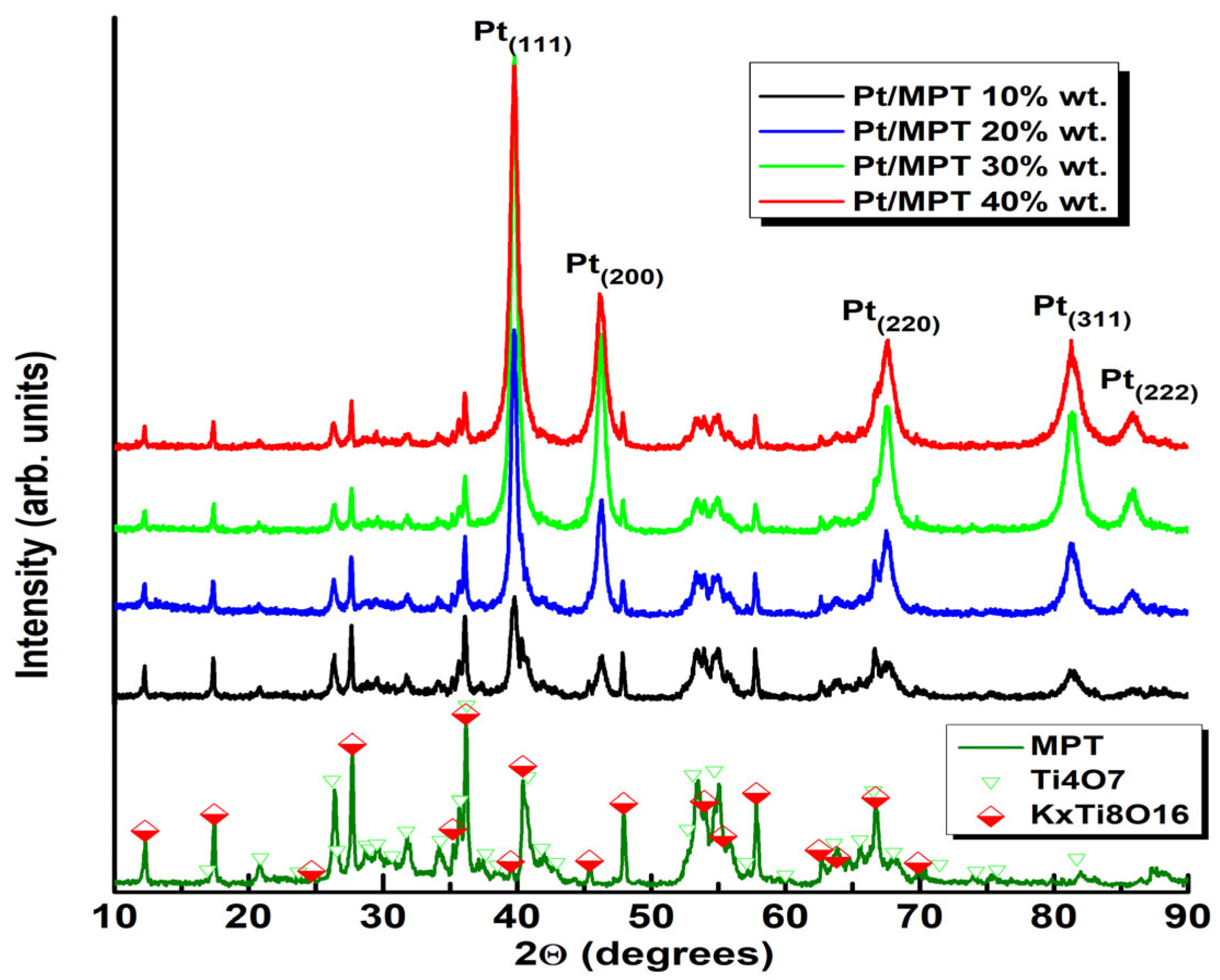
| Sample | Crystal Size | |||
|---|---|---|---|---|
| (111) | (200) | |||
| FWHM | Width | FWHM | Width | |
| Pt/MPT 10% wt. | 16 (2) | 12 (2) | 11 (1) | 10 (1) |
| Pt/MPT 20% wt. | 18 (1) | 13 (1) | 12 (1) | 10 (1) |
| Pt/MPT 30% wt. | 16 (1) | 12 (1) | 12 (1) | 9 (1) |
| Pt/MPT 40% wt. | 13 (1) | 9 (1) | 9 (1) | 7 (1) |
| Characteristics | Pt/MPT 10% wt. | Pt/MPT 20% wt. | Pt/MPT 30% wt. | Pt/MPT 40% wt. |
|---|---|---|---|---|
| Surface area MP [m3/g] | 15.3 | 17.5 | 9.8 | 7.7 |
| Surface area SP [m3/g] | 13.0 | 13.4 | 8.7 | 6.0 |
| Total pore volume [cm3/g] | 0.037 | 0.039 | 0.023 | 0.018 |
| Average pore diameter [nm] | 9.7 | 9 | 9.2 | 9.5 |
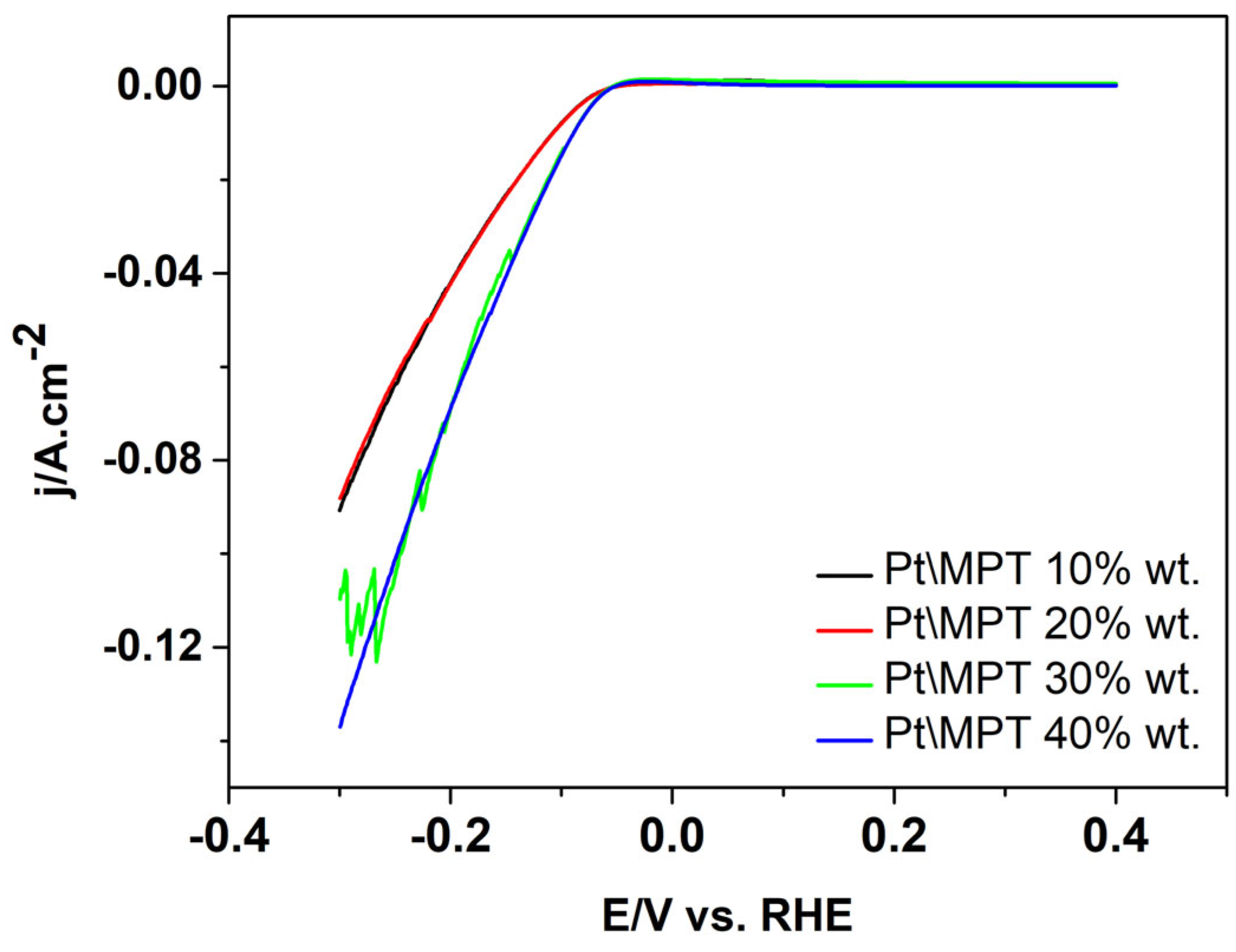
| Sample | Active Area [cm2] | Overpotential [V] |
|---|---|---|
| Pt/MPT 10% wt. | 1.02 | −0.063 |
| Pt/MPT 20% wt. | 1.12 | −0.063 |
| Pt/MPT 30% wt. | 1.18 | −0.059 |
| Pt/MPT 40% wt. | 1.25 | −0.058 |
Disclaimer/Publisher’s Note: The statements, opinions and data contained in all publications are solely those of the individual author(s) and contributor(s) and not of MDPI and/or the editor(s). MDPI and/or the editor(s) disclaim responsibility for any injury to people or property resulting from any ideas, methods, instructions or products referred to in the content. |
© 2025 by the authors. Licensee MDPI, Basel, Switzerland. This article is an open access article distributed under the terms and conditions of the Creative Commons Attribution (CC BY) license (https://creativecommons.org/licenses/by/4.0/).
Share and Cite
Borisov, G.R.; Borisov, N.R.; Slavcheva, E. Non-Carbon-Supported, Pt-Based Catalysts with Applications in the Electrochemical Hydrogen Pump/Compressor (EHP/C). Appl. Sci. 2025, 15, 6507. https://doi.org/10.3390/app15126507
Borisov GR, Borisov NR, Slavcheva E. Non-Carbon-Supported, Pt-Based Catalysts with Applications in the Electrochemical Hydrogen Pump/Compressor (EHP/C). Applied Sciences. 2025; 15(12):6507. https://doi.org/10.3390/app15126507
Chicago/Turabian StyleBorisov, Galin Rusev, Nevelin Rusev Borisov, and Evelina Slavcheva. 2025. "Non-Carbon-Supported, Pt-Based Catalysts with Applications in the Electrochemical Hydrogen Pump/Compressor (EHP/C)" Applied Sciences 15, no. 12: 6507. https://doi.org/10.3390/app15126507
APA StyleBorisov, G. R., Borisov, N. R., & Slavcheva, E. (2025). Non-Carbon-Supported, Pt-Based Catalysts with Applications in the Electrochemical Hydrogen Pump/Compressor (EHP/C). Applied Sciences, 15(12), 6507. https://doi.org/10.3390/app15126507