Article

The Effect of Stress Distribution on Tibial Implants with a Honeycomb Structure in Open-Wedge High Tibial Osteotomy

Hebei Key Laboratory of Biomaterials and Smart Theranostics, School of Health Sciences and Biomedical Engineering, Hebei University of Technology, Tianjin 300131, China
*
Author to whom correspondence should be addressed.
These authors contributed equally to this work.
Appl. Sci. 2025, 15(12), 6467; https://doi.org/10.3390/app15126467
Submission received: 22 April 2025 / Revised: 19 May 2025 / Accepted: 2 June 2025 / Published: 9 June 2025
(This article belongs to the Section Materials Science and Engineering)

Abstract

:

Featured Application

The combination of finite element analysis and in vitro biomechanical experiments can provide a more comprehensive mechanical evaluation for tibial implants, thereby guiding their structural design.

Abstract

A tibial implant is necessary to provide mechanical support in open-wedge high tibial osteotomy (OWHTO) treatment of knee osteoarthritis. The pore structure and porosity of implants exert significant effect on tibia stress distribution and lower limb alignment stability. In this study, finite element (FE) analysis and in vitro biomechanical experiments were utilized to evaluate the impact of different tibial implants on postoperative tibial stress distribution. The biomechanical experimental results of experiments on tibial implants exhibit similar mechanical response patterns to the established finite element model, whose maximum displacement error is 1.18% under 1500 N compressive load. The hybrid porous implant developed in this study demonstrated significant stress reductions in both tibial bone (19.97% and 15.33% lower than mono-porous configurations at 73% porosity) and implant body (31.60% and 11.83% reductions, respectively), while exhibiting diminished micromotion tendencies. This consistent performance pattern was maintained across the entire porosity spectrum (53–83%) in implanted specimens. In summary, the finite element model established using authentic tibial CT data can effectively guide the structural design of tibial implants, and optimized pore structure design can provide enhanced mechanical support effects for tibial implants.

1. Introduction

Knee osteoarthritis is a disease primarily caused by degenerative pathological changes, often induced by factors such as trauma and overuse, which severely impacts patients’ quality of life and restricts social productivity [1,2,3]. The knee joint is the most frequently affected human joint, and the global prevalence of knee osteoarthritis is high. It is projected that the global population affected by knee osteoarthritis will reach 642 million by 2050 [4]. High tibial osteotomy (HTO), as a preferred joint-preserving surgical procedure for knee osteoarthritis with varus deformity, corrects lower limb alignment to modify weight distribution on the tibial plateau, thereby reducing pressure on the medial compartment and slowing osteoarthritis progression. This procedure is particularly recommended for younger and highly active patients due to its capacity to allow relatively rapid recovery, enabling a swift return to daily activities [5,6,7].
The current standard HTO technique involves resecting a wedge-shaped bone segment from the proximal tibia, followed by fixation with bone plates. However, this approach presents significant limitations, including substantial tissue trauma, delayed postoperative weight-bearing, high implant costs, and elevated complication rates [8,9,10]. Clinicians are now exploring alternative strategies utilizing tibial implants to fill osseous defects and mechanically elevate the medial plateau. This innovative method obviates plate fixation, permits immediate weight-bearing post-implantation, and demonstrates reduced complication incidence [11,12,13]. The absence of plate-mediated structural support imposes stringent mechanical requirements on defect-filling implants, particularly regarding compressive strength and shear resistance. Emerging clinical observations reveal two critical challenges associated with conventional implants: stress-shielding effects and progressive implant loosening. In response to these issues, more and more researchers are adopting bioinspired porous architectures for orthopedic implant design. These biomimetic structures aim to optimize stress distribution patterns while preserving essential mechanical stimuli to facilitate physiological bone remodeling processes [14,15,16,17,18].
An increasing number of studies have focused on the structural design of tibial implants. Research has demonstrated that porous structures with tunable pore size and porosity can effectively reduce stress shielding caused by solid metal implants and serve as viable replacements for damaged bone [19,20]. These porous structures not only lower the elastic modulus of materials but also promote osseointegration and bone ingrowth, thereby enhancing implant stability [21,22,23]. The design of porous structures relies on the innovation and imagination of researchers to achieve the desired mechanical properties. Through millions of years of evolution, nature has developed numerous porous architectures, such as honeycomb structures, coral structures, insect cuticle structures, and bamboo structures [24,25,26,27,28], which provide biomimetic inspiration for porous structure design and have been applied in bone implant development with increasing frequency [29,30,31,32]. Honeycomb materials, as natural structures found in nature, have attracted significant attention due to their unique geometry and exceptional mechanical properties. Their core characteristic lies in achieving lightweight and high specific strength through rational geometric design. Composed of periodic unit cells, honeycomb materials exhibit ultralight weight, low relative density, high specific stiffness, high specific strength, and strong energy absorption [33,34,35,36,37]. Unlike traditional materials, the mechanical performance of honeycomb materials primarily stems from their topological structural features. Consequently, rational artificial structural design of honeycomb materials has become a critical approach for enhancing their mechanical properties [38,39,40,41,42,43].
Due to individual variations in patient skeletal morphology and pathological conditions, the structural design and fixation methods of various implants lead to differential clinical outcomes. However, in vivo experiments are constrained by engineering ethics and their inherent technical challenges, which has resulted in the widespread application of finite element analysis in postoperative mechanical evaluation and implant optimization studies [44,45,46]. According to our investigation, most research on postoperative tibial mechanical evaluation has been conducted solely from the perspective of finite element analysis. However, these investigations typically adopt third-party standardized human bone models [47,48,49,50] or bone models similar to the study subjects [51,52], which fail to provide effective mechanical assessments for personalized tibial implant design.
This study addresses the bone defect repair requirements following HTO by proposing a personalized tibial implant design method based on a composite metamaterial structure, with its mechanical performance validated through integrated finite element analysis and biomechanical experiments. Building upon our prior research, a novel metamaterial structure was implemented in HTO-specific tibial implants. The term “composite metamaterial” in this study refers to an engineered porous material with tunable mechanical properties, formed by hybridizing two distinct unit cell structures. Its mechanical performance surpasses that of conventional materials. Mechanical finite element models and biomechanical experimental setups were established to investigate the mechanical response characteristics of the metamaterial-structured implants compared to conventional pore configurations (square and circular) when implanted in bone defect sites, employing combined finite element simulations and compression testing. This work provides a solution for post-HTO bone defect repair that simultaneously addresses osseointegration and mechanical performance, offering a theoretical foundation for the development and clinical application of personalized orthopedic implants.

2. Materials and Methods

2.1. Finite Element Analysis

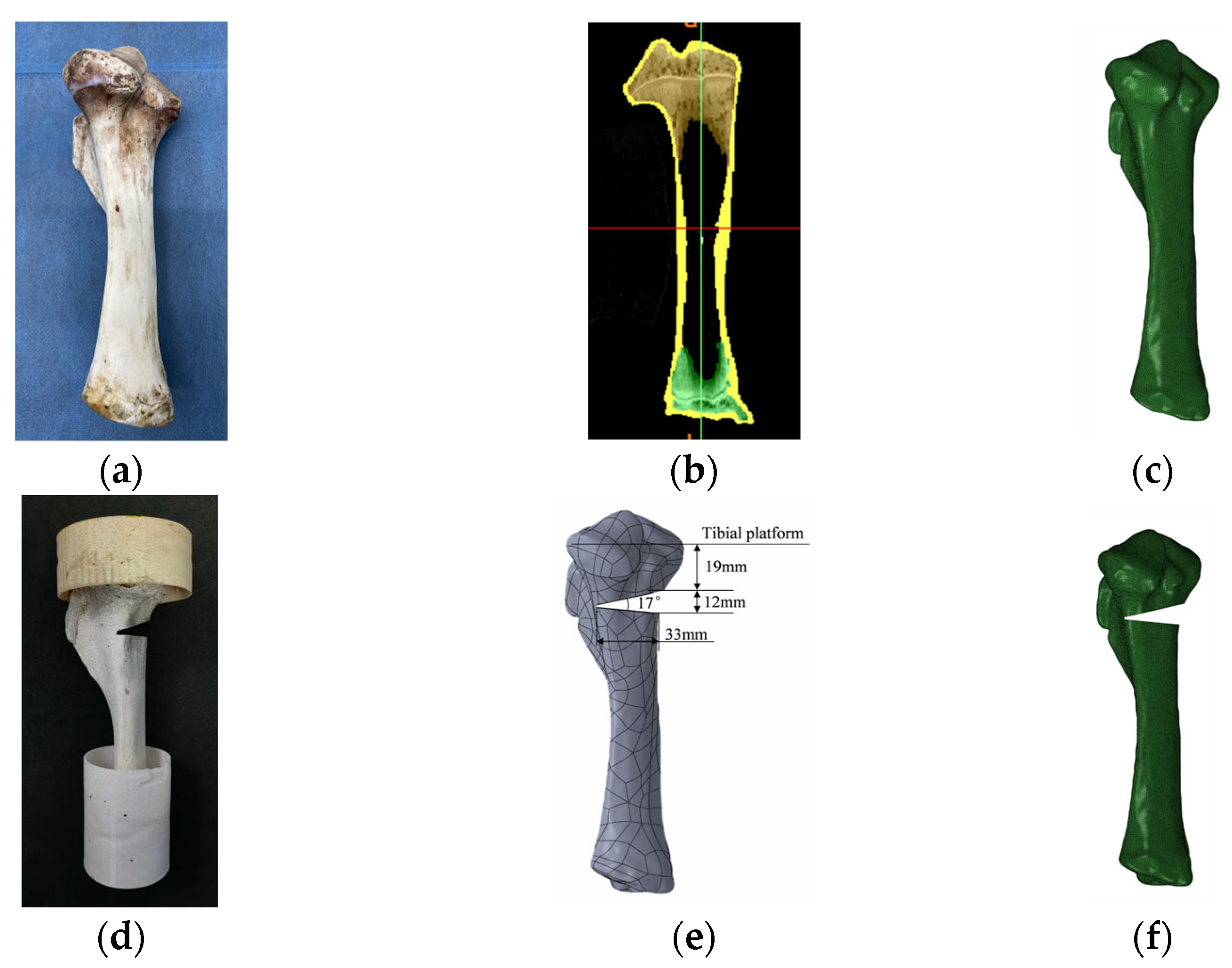
2.1.1. Model Construction

With respect for the dignity of life and compliance with research ethics guidelines, the tibia specimen (Figure 1a) used in this study was obtained from a 6-month-old commercially farmed pig procured from a licensed slaughterhouse (all procedures adhered to approved protocols), confirming that the animals were not slaughtered for experimental purposes but for commercial use. First, the porcine tibia was scanned using a computed tomography (CT) scanner (GE Ltd., Boston, MA, USA) with a slice thickness of 0.6 mm. The DICOM-format CT images (Figure 1b) were then imported into Mimics Research 21.0 software (Materialise, Leuven, Belgium) for three-dimensional reconstruction of the porcine tibia. To enhance the reliability of finite element simulations, cancellous and cortical bone regions were differentiated via grayscale thresholding, while preserving the hollow medullary cavity within the tibia. After optimizing the model into solid components using Geomagic Wrap 2021 (Geomagic Inc., RTP, NC, USA), medial tibial osteotomy was performed in SolidWorks 2022 (Dassault Systèmes SolidWorks Corp., Waltham, MA, USA) following HTO surgical specifications, and the resulting tibial defect model is illustrated in Figure 1e,f.
A contour-adapted personalized tibial implant for HTO was designed based on the morphology of the bone defect area. The implant incorporates a porous structure design, with its composite pore configuration developed according to previous research findings as an artificially designed internal topological structure—a metamaterial honeycomb system. Both square and circular pores represent conventional design approaches. All porous tibial implants with different structures were parameter-adjusted to achieve four porosity levels, and the specific parameters are detailed in Table 1. The implants were geometrically positioned within the osteotomy gap of the tibial model to establish postoperative HTO tibial models containing three distinct structural configurations with four porosity gradients (Figure 2a). All models were imported into HyperMesh 2022 (Altair Engineering Inc., Michigan, USA) for meshing into C3D4 tetrahedral elements suitable for finite element analysis.

2.1.2. Materials Properties and Interactions

The material properties of all finite element model components were referenced from previous studies [53,54]. All components were idealized as homogeneous, isotropic linear elastic materials. This configuration aimed to facilitate qualitative comparisons between different tibial implant configurations through uniform simplification of material treatment. The mechanical behavior of the metamaterial is predominantly governed by structural deformation mechanisms inherent to its internal architecture. Consequently, the adoption of linear elastic finite element analysis, which neglects plastic deformation of the resin-based implant material, remains justifiable in this context. The material properties of cortical bone, cancellous bone, and tibial implants are detailed in Table 2. The interface between cortical and cancellous bone was defined as bonded contact to simulate natural osseous integration. Surface-to-surface contact, with separation and sliding permitted, was established between the tibial implant and both bone types, featuring hard contact in the normal direction and frictional contact (coefficient = 0.3) in the tangential direction [54,55].

2.1.3. Boundary and Loading Conditions

In the experiment, distributed coupling constraints were employed to apply loads. A reference point was established 2 mm above the tibial plateau and connected to the entire tibial plateau reference surface through a coupling binding configuration. Loading conditions were defined according to realistic physiological scenarios. An adult-sized pig weighing approximately 150 kg generates a ground reaction force of 375 N per limb during quadrupedal standing (a quarter of its total body weight). During walking, where load bearing is primarily supported by two limbs in quadrupedal animals, the force per limb increases to 750 N. For running activities, which involve both body weight and dynamic impact loads, we categorized running as trotting or galloping based on intensity. Trotting and galloping were simulated with applied forces of 1000 N and 1500 N, respectively. Physiological loads of 375 N, 750 N, 1000 N, and 1500 N were applied at the reference point to simulate axial compressive loads transmitted from the knee joint to the tibia during four physiological activities: standing, walking, jogging, and running. In all finite element simulations, the distal end of the tibial osteotomy model was fully constrained.

2.2. Experimental Research

2.2.1. Specimens

The tibial specimen ends were encapsulated in denture base resin material using molds, with embedding depths matching the boundary constraints in the finite element model (Figure 1d). This approach not only facilitated subsequent compression testing but also enabled validation of the finite element model’s accuracy. Following HTO surgical specifications, medial osteotomy was performed on the tibial specimens using standard surgical instruments following clinical protocols. All designed porous tibial implants with varying pore structures and porosity levels were fabricated via 3D printing technology using an ELEGOO Mars 5 Ultra SLA 3D printer (ELEGOO Ltd., Shenzhen, China) with rigid photopolymer resin, as illustrated in Figure 2b. Prior to testing, all experimental specimens were uniformly coated with randomized black speckle patterns using spray paint to facilitate deformation tracking by digital image correlation (DIC) systems.

2.2.2. Experimental Stand

The intact tibia was positioned in a universal testing machine (SUNS Inc., Shenzhen, China) for compression testing and loaded under a constant rate of 100 N/s until reaching 1500 N. A digital image correlation (DIC) system (XTOP Inc., Shenzhen, China) performed continuous recording throughout the compression process, with the full experimental setup illustrated in Figure 3a.

3. Results

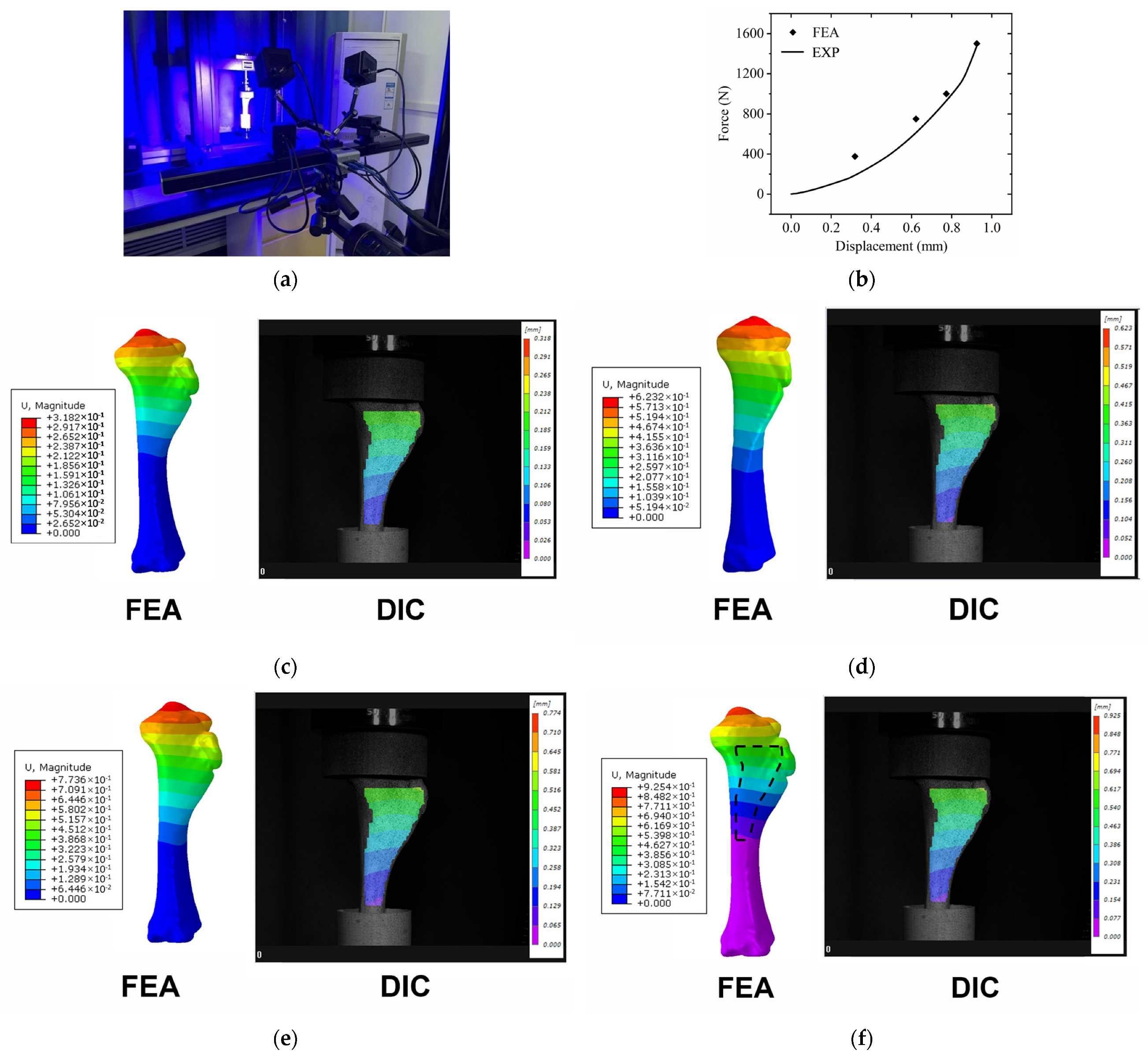
3.1. Validation of FE Model

The force–displacement curve of the intact tibia model obtained from mechanical testing and finite element simulation results under different loads are plotted in Figure 3b, revealing a non-linear mechanical response of the tibia, with a displacement of 0.936 mm at 1500 N loading. Figure 3c–f present the displacement field contour plots from finite element simulations under simulated physiological loading conditions of standing (375 N), walking (750 N), jogging (1000 N), and sprinting (1500 N), along with the corresponding displacement field contour plots captured using the DIC device. The simulated displacement patterns (denoted by black dashed lines) exhibit high consistency with DIC-measured actual displacement distributions, both demonstrating cumulative displacement from distal to proximal regions, with maximum displacement occurring at the proximal tibia and progressively decreasing towards the distal end. The finite element simulation yielded a maximum displacement of 0.925 mm under 1500 N loading, showing a 1.18% error compared to experimental measurements.
Finite element simulation results of stress and strain distributions in the intact tibia under different physiological activities are presented in Figure 4a–d and Figure 4e–h, respectively, showing both surface and cross-sectional simulation results of the tibial model. The simulation results reveal that under physiological loading, stress was predominantly concentrated in the cortical bone region subjacent to the medial tibial plateau, while strain was observed in both cortical and cancellous bone regions of the medial tibial plateau subjacent area. The maximum stress and strain values from the simulations are statistically summarized in Figure 4i,j. As the simulated physiological loads increased, corresponding to different activity intensities, both peak stress and strain values in the tibia demonstrated progressive elevation. From standing (lowest load) to running (highest load), the maximum stress in the intact tibia increased from 3.94 MPa to 15.76 MPa, while the maximum strain rose from 0.017% to 0.067%.

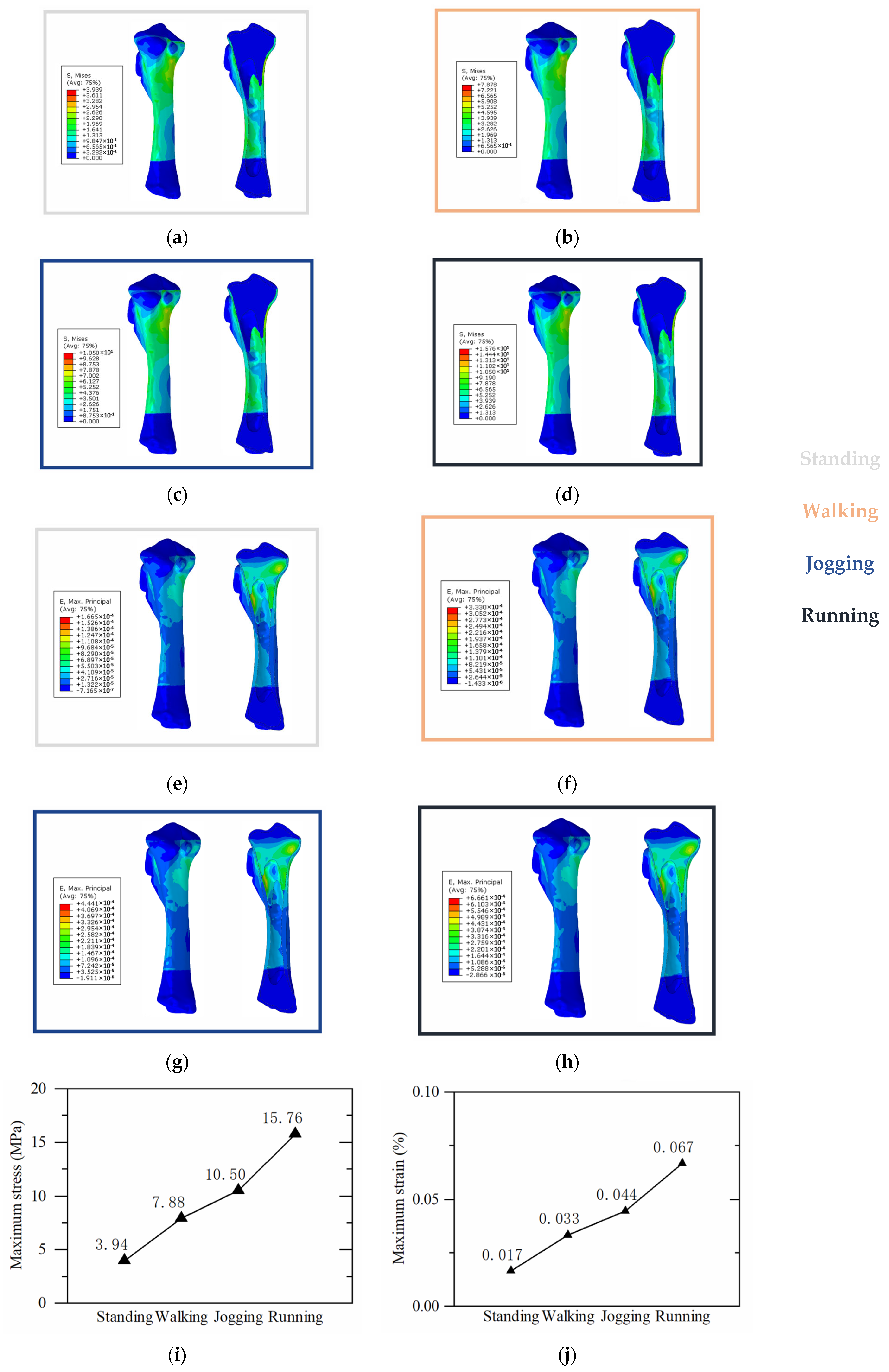
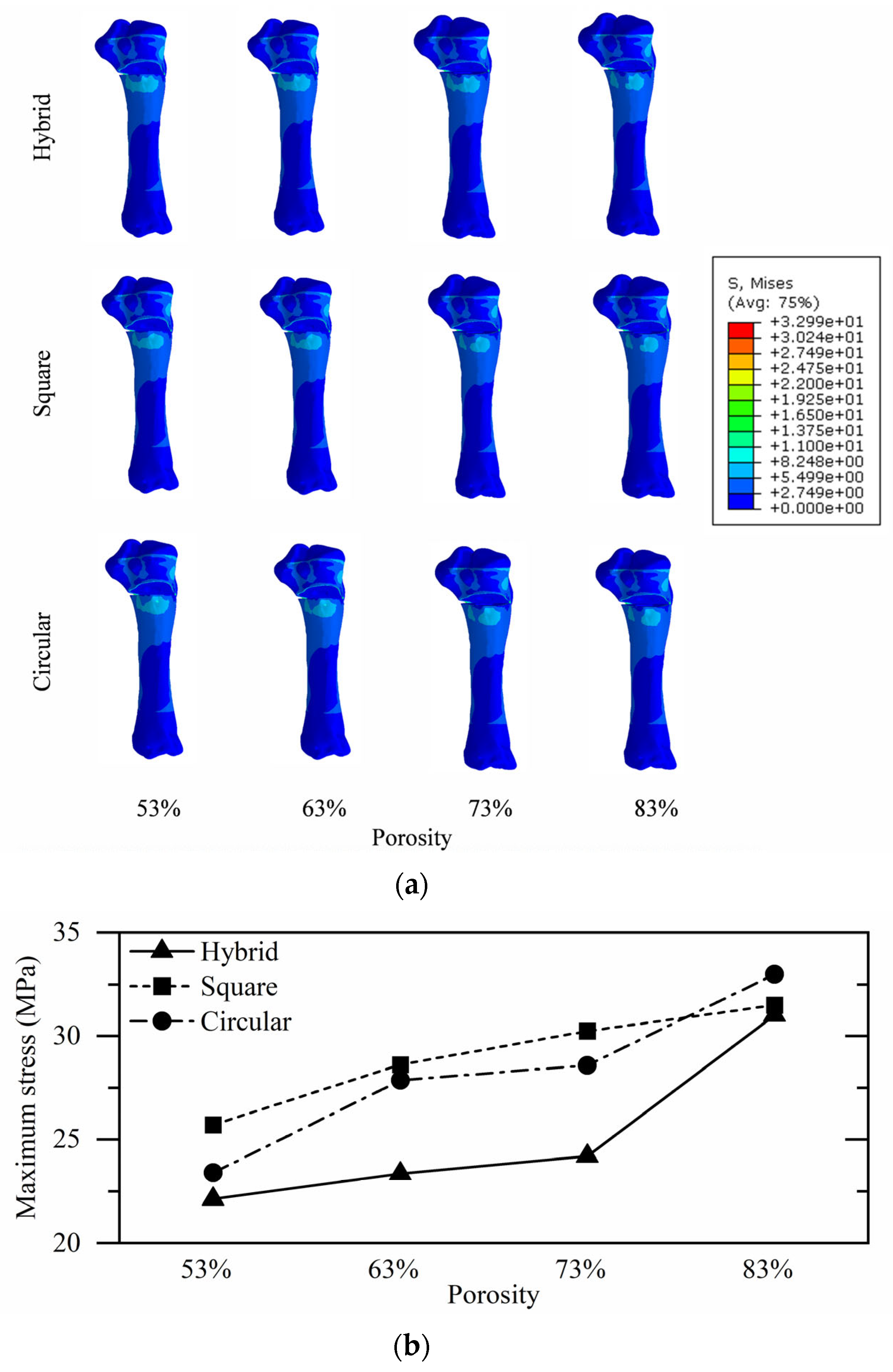
3.2. Proximal Tibial Stress Analysis

As shown in Figure 5a, the peak proximal tibial stresses in all osteotomy models consistently occurred at the posterior aspect of the lateral hinge. Among the three porous structural configurations, tibial osteotomy models implanted with composite pore structures exhibited the lowest proximal stresses, a trend which was also observed across implants with different porosity levels. As the implant porosity increased, the tibial maximum stress demonstrated a consistent increasing trend. However, a notable exception was observed at 83% porosity, where circular-porous implants induced higher tibial maximum stress compared to square-porous implants. At other porosity levels, the maximum stress adhered to the following hierarchy: square-porous > circular-porous > hybrid-porous implants. Within the 53% to 83% porosity range, compared to composite pore implants, circular pore implants increased the maximum proximal stresses in osteotomy models by 5.79%, 19.37%, 18.10%, and 6.39%, respectively, while square pore implants elevated these stresses by 16.23%, 22.58%, 24.96%, and 1.58%. The maximum stress values of osteotomy models implanted with different porous structures are graphically presented in Figure 5b, with numerical data systematically compiled in Table 3.

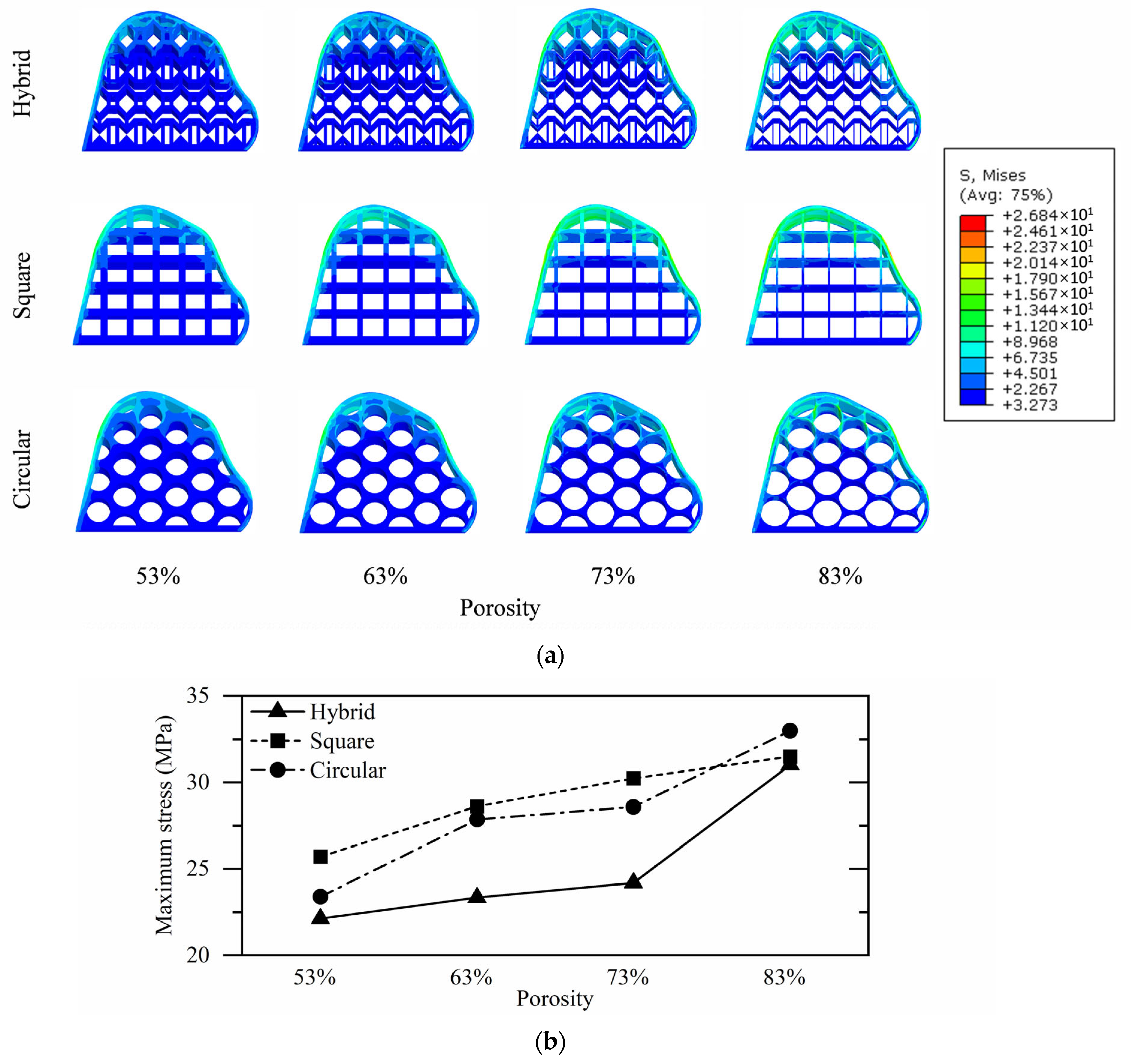
3.3. Tibial Implant Stress Analysis

As shown in Figure 6a, stress concentration in tibial implants predominantly occurred at the cortical bone contact regions, representing the primary load-bearing interface between the implant and postoperative tibia. Among the configurations, composite pore structure implants demonstrated the lowest stress levels, with maximum stress values of 12.33 MPa, 13.62 MPa, 15.95 MPa, and 20.69 MPa at porosities ranging from 53% to 83%. Compared to circular pore implants, these values represent stress reductions of 14.43%, 6.39%, 11.83%, and 5.57%, respectively, while relative to square pore implants, reductions reached 26.03%, 23.31%, 31.60%, and 22.91%. The maximum stress values of tibial implants across varying porous architectures and porosity levels are systematically compiled in Table 4 and graphically presented in Figure 6b.

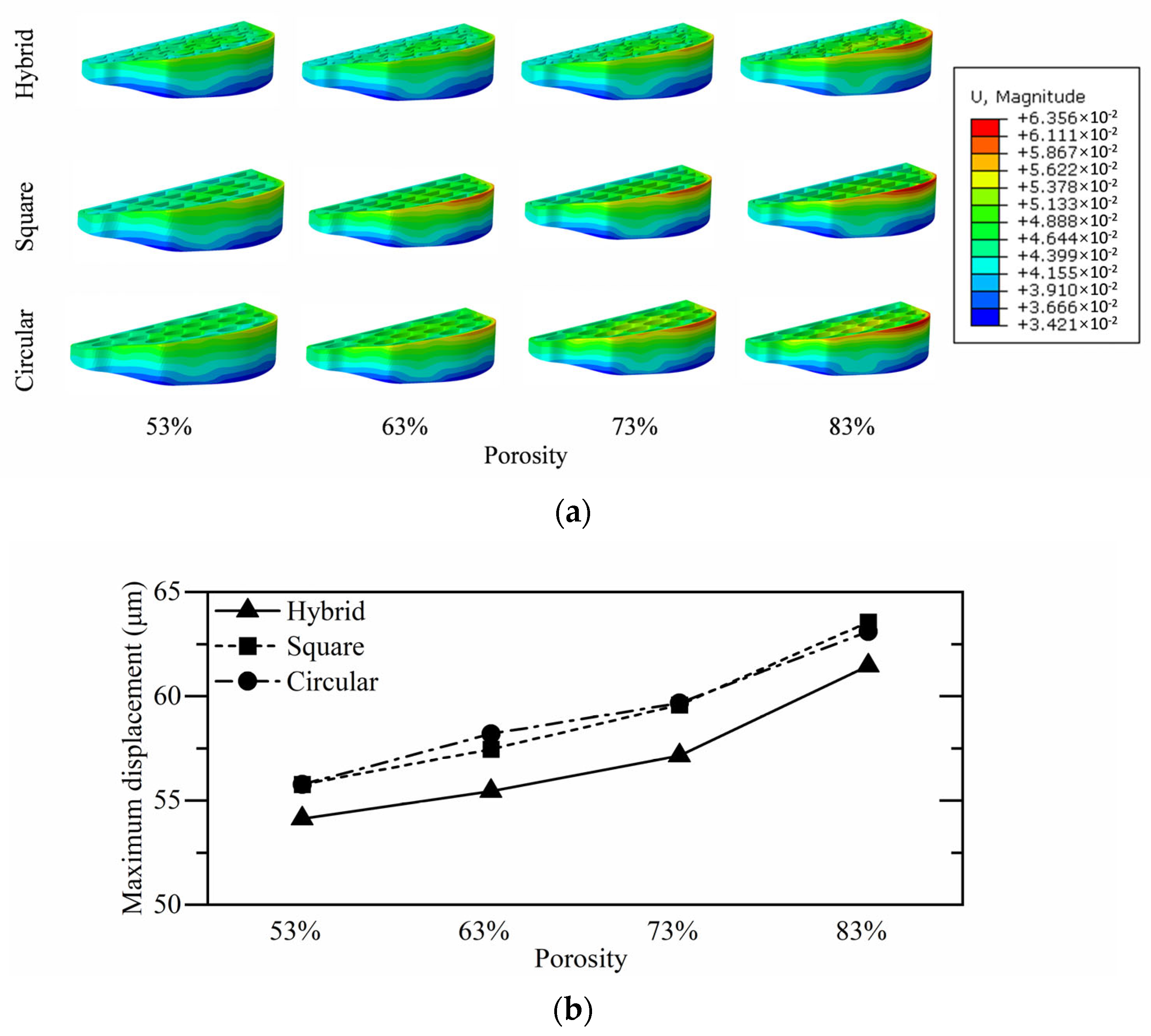
3.4. Tibial Implant Micromotion Analysis

Micromotion tendencies in tibial implants under compressive loading at the bone defect site arise from compression within the open-wedge defect region. As depicted in Figure 7a, among implants with varying porosities, composite pore structure implants consistently demonstrated the minimal edge displacement, while circular and square pore configurations exhibited comparable displacement magnitudes. At porosities ranging from 53% to 83%, composite pore implants showed edge displacements of 54.13 μm, 55.45 μm, 57.15 μm, and 61.47 μm, respectively. Compared to circular pore implants, these values represent displacement reductions of 2.94%, 4.73%, 4.24%, and 2.60%, while relative to square pore implants, reductions reached 2.94%, 3.50%, 4.09%, and 3.29%. The maximum displacement values of tibial implants across different porous architectures and porosity levels are systematically compiled in Table 5 and graphically presented in Figure 7b.

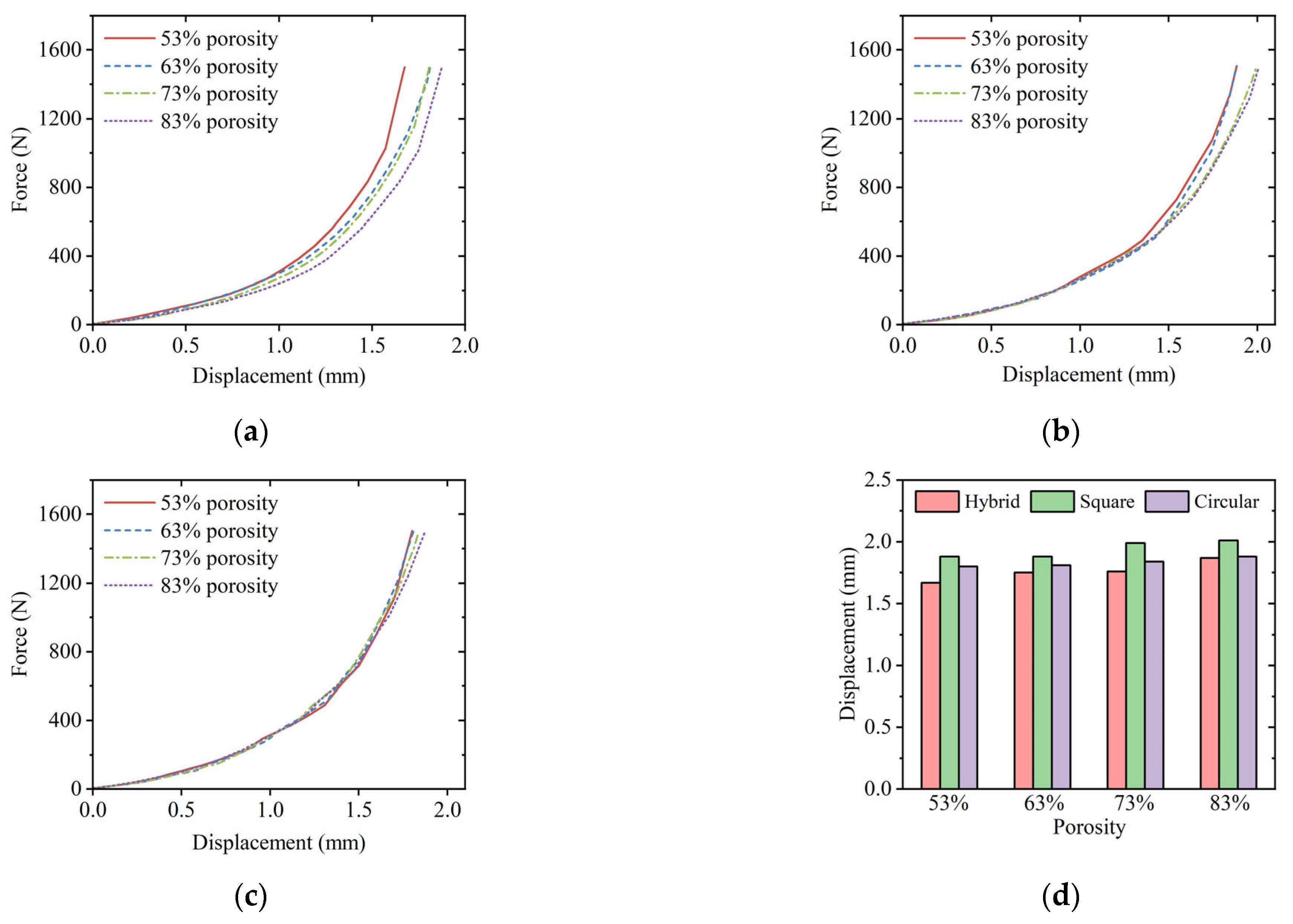
3.5. Postoperative Tibial Biomechanical Experiments

The compression test results of bone defect models implanted with different structural configurations are plotted in Figure 8a–c; their displacement values under 1500 N loading are statistically summarized in Figure 8d. Analysis of these force–displacement curves reveals that the compressive mechanical responses of post-HTO porcine tibiae demonstrate similarities to those of intact specimens, exhibiting comparable non-linear relationships and growth trends. This indicates that tibial implants effectively restore native mechanical functionality within the defect region. While high-porosity implant configurations showed marginally inferior mechanical support capacity compared to their low-porosity counterparts—attributable to reduced base material usage—no structural collapse or dislodgement from the defect site was observed in any high-porosity implants.

4. Discussion

Postoperative experimental evaluations of tibial implants used in HTO procedures have rarely been conducted due to a series of limitations, most notably the inability to perform in vivo experiments on human bone. This study utilized porcine bone, which shares the same heterogeneous structure (including cancellous and cortical bone) as human bone, for postoperative experimental assessments. A three-dimensional model replicating the internal structure of actual porcine tibia was constructed, and its stress distribution under compressive conditions was analyzed through finite element analysis. The use of porcine bones as substitutes for human bone models in biomechanical studies represents a common practice when human specimens present ethical challenges and accessibility limitations. However, this approach does carry inherent constraints, such as the generally lower bone density of porcine specimens compared to human bone and the morphological differences between porcine and human tibiae. Nevertheless, this study focuses on developing a method for personalized customization of bone implants. Considering the significant morphological variations among individual human bones, the mechanical testing results from porcine models have already demonstrated that constructing authentic tibial geometric models based on CT scan data substantially enhances the correlation between simulation outcomes and biological reality. Therefore, the adoption of porcine models does not compromise the applicability of this methodology.
The stress distribution on the tibia exhibited relatively uniform variations within the loaded region, with areas of higher equivalent stress concentrated beneath the tibial plateau. The equivalent stress nephogram of the tibial cross-section reveals that due to distinct material properties between cortical and cancellous bone—particularly the significantly higher Young’s modulus of cortical bone compared to cancellous bone—the cortical bone bears the majority of loads transmitted from the tibial plateau, making it the primary load-bearing component in the tibial structure during physiological activities. The stress nephogram demonstrates dense stress concentration zones throughout the cortical bone, particularly in the upper-middle region of the tibia, while the cancellous bone, characterized by its porous structure and lower modulus, only sustains minimal dispersed loads. Mechanical testing displacement data showed close agreement with finite element simulation results, validating that obtaining precise tibial geometry through CT scanning and differentiating bone regions in the finite element model can better simulate the mechanical responses of real tibia under physiological conditions. The established finite element model of tibial mechanics demonstrates enhanced accuracy, providing effective guidance for subsequent design of tibial spacers. Both the finite element simulation displacement nephogram and the DIC nephogram from in vitro mechanical tests exhibited a superimposed state from distal to proximal regions, with maximum displacement observed at the proximal tibia gradually decreasing towards the distal end.
Finite element simulation results of equivalent stress distribution demonstrate relatively uniform stress variations across loaded tibial regions, with elevated equivalent stress concentrations primarily localized beneath the tibial plateau. As physiological activity intensity escalates, corresponding to increased loading magnitudes from 375 N to 1500 N, the maximum equivalent stress in the tibia displays a progressive elevation, increasing from 3.94 MPa during standing to 15.76 MPa during running. Cross-sectional equivalent stress contour plots reveal distinct load-bearing patterns between cortical and cancellous bone, which are attributable to their material property disparities. The cortical bone, characterized by a Young’s modulus significantly exceeding that of cancellous bone, bears the predominant mechanical load transmitted from the tibial plateau, serving as the primary load-bearing component during physiological activities. Stress visualization demonstrates dense stress concentration bands throughout cortical regions, particularly concentrated in the mid-proximal tibial section. Conversely, cancellous bone, owing to its porous architecture and lower modulus, exhibits minimal dispersed stress distribution. This mechanical load-sharing pattern aligns with structural analyses reported in previous studies, where the cortical bone’s dense Haversian systems establish optimized load transmission pathways.
Analysis of maximum equivalent strain data reveals progressive strain escalation in the tibia with increasing physiological activity intensity, as loads transmitted through the tibial plateau intensify from standing (0.017%) to running (0.067%). Strain distribution patterns in the intact tibia demonstrate concentrated deformation zones within block-shaped regions of the medial area inferior to the tibial plateau, correlating spatially with high-stress distributions observed in corresponding stress contour maps. This spatial congruence indicates that regions experiencing greater deformation simultaneously bear elevated mechanical stresses. Cross-sectional strain analysis reveals significantly elevated strain values throughout the proximal cancellous bone region, extending from cortical–cancellous junctions to the internal cancellous architecture. This strain distribution pattern aligns with the porous morphological characteristics of cancellous bone. Notably, high-strain regions in cancellous bone exhibit continuity with cortical bone strain concentrations, demonstrating mechanical coupling where cancellous deformation originates from load transmission through cortical bone. These observations validate the effectiveness of modeling cortical–cancellous interactions as a bonded interface in simulating physiological load transfer mechanisms within the finite element framework.
According to finite element analysis results of the tibia following HTO surgery, the region with maximum stress concentration was identified at the osteotomized hinge area. The primary purpose of tibial implantation is to replace resected bone mass and optimize lower limb mechanical alignment modification, thereby enhancing physiological load transmission. As the porosity of the tibial implant increased, the peak stress on the tibia progressively elevated, indicating reduced load-bearing capacity in high-porosity implants. Nevertheless, hybrid porous-structured implants demonstrated superior stress distribution across all porosity ranges. Specifically, under 73% porosity conditions, hybrid porous implants achieved optimal mechanical load transfer efficiency without inducing stress concentration in the tibia. Compared to circular and rectangular porous configurations at equivalent porosity levels, the hybrid structure reduced tibial peak stress by 19.97% and 15.33%, respectively.
The analysis of stress contour maps across various tibial implants reveals no significant stress concentration within the implant structures. Lower stress values were observed at the cancellous bone interface, whereas higher stresses were concentrated in regions directly interfacing with cortical bone. With increasing porosity, all implant configurations exhibited elevated maximum von-Mises stresses—a phenomenon attributable to reduced material volume in the load-bearing matrix and structural thinning, which amplifies stress intensification in supporting frameworks. Notably, composite porous implants demonstrated superior stress distribution characteristics compared to circular and rectangular porous designs. At 83% porosity, the composite configuration achieved a peak equivalent stress of 20.69 MPa, representing reductions of 22.91% and 5.52% relative to rectangular and circular porous counterparts, respectively.
From the displacement cloud map, it can be seen that the displacement of all implant structures is basically in a layered state, indicating that the main displacement trend is dominated by the direction of force loading, and there are not too many slip trends that are different from the direction of force loading. With the continuous increase in porosity, the maximum displacement values on tibial implants of different structures all increase. This is due to the increase in porosity, which reduces the matrix material used to support the implant and leads to a decrease in its ability to resist deformation. The tibial implant with a composite pore structure exhibited smaller micro movements, indicating its strong anti-slip ability. The edge displacement of all models in this article did not exceed the maximum allowable movement for bone healing.
The results of the biomechanical experiments demonstrate that the maximum tibial displacement exhibits an increasing trend as the porosity of the implanted tibial inserts increases, indicating reduced overall implant stiffness at higher porosity levels. When porosity increased from 53% to 83%, tibiae implanted with composite, square, and circular pore structures showed displacement increments of 11.98%, 6.91%, and 4.44%, respectively. Notably, while composite pore implants demonstrated the steepest displacement growth rate, they consistently exhibited the lowest absolute displacement values across all porosity levels, reflecting superior mechanical stability during porosity escalation. Distinct performance variations emerged among pore architectures under equivalent porosity conditions. At 53% porosity, composite pore implants achieved 1.67 mm displacement, representing 11.17% and 7.22% reductions compared to square (1.88 mm) and circular (1.80 mm) pore configurations. This advantage intensified at 83% porosity, where composite pore implants recorded 1.87 mm displacement, outperforming square (2.01 mm) and circular (1.88 mm) designs by 6.97% and 0.53%, respectively. It is worth noting that circular pore implants demonstrated secondary performance to composite structures at lower porosities (53–63%), but exhibited accelerated displacement growth when porosity exceeded 73%. Square pore configurations consistently produced the highest displacements in all biomechanical tests, peaking at 2.01 mm (83% porosity)—7.49% greater than their composite counterparts. Comprehensive analysis confirms that composite pore implants exhibit enhanced mechanical stability through their hybrid pore architecture, which significantly improves load-bearing capacity while maintaining osteointegration-essential porous spaces. Across the full 53–83% porosity spectrum, these implants achieved minimal postoperative tibial displacements (1.67–1.87 mm), outperforming conventional single-pore designs by 7.0–12.0%. These findings substantiate the composite structure’s exceptional balance between high porosity requirements and mechanical performance preservation.

5. Conclusions

In conclusion, this research adopted an integrated approach combining finite element analysis with in vitro mechanical experiments, which not only validated the high accuracy of finite element models derived from CT scan data but also confirmed the practical mechanical support efficacy of the designed tibial implant. The novel hybrid-porous implant developed in this study demonstrated superior mechanical support efficacy compared to conventional square- and circular-porous designs. At 73% medium-high porosity, implantation of hybrid-porous devices resulted in 19.97% and 15.33% reductions in tibial maximum stress relative to traditional square-porous and circular-porous implants, respectively, with concomitant reductions of 31.60% and 11.83% in implant maximum stress, alongside 4.09% and 4.24% decreases in marginal displacement. This advantageous performance profile remained consistent across the full porosity spectrum. Biomechanical testing revealed that hybrid-porous tibial implants demonstrated superior performance across the full porosity range (53–83%), maintaining minimal post-implantation displacement values (1.67–1.87 mm) which were 7.0–12.0% lower than those observed with conventional mono-porous implant configurations. This study demonstrates that variations in structural configuration and porosity significantly influence postoperative tibial stress distribution, which contributes to improved mechanical environments in high tibial osteotomy treatment of knee osteoarthritis.

Author Contributions

Conceptualization, Z.X. and Y.X.; methodology, Z.X. and C.M.; software, Z.X.; validation, Z.X. and C.M.; formal analysis, Z.X.; investigation, C.M.; resources, Y.X.; data curation, Y.X. and Z.X.; writing—original draft preparation, Z.X.; writing—review and editing, Y.X. and C.M.; visualization, Z.X.; supervision, Y.X.; project administration, Y.X.; funding acquisition, Y.X. All authors have read and agreed to the published version of the manuscript.

Funding

This research was funded by Natural Science Foundation of Hebei Province of China, grant number C2023202010; Full-time Talents Program of Hebei Province of China, grant number HY2024050012; National Natural Science Foundation of China, grant number U23A6008.

Institutional Review Board Statement

Not applicable.

Informed Consent Statement

Not applicable.

Data Availability Statement

The data presented in this study are available in the article.

Conflicts of Interest

The authors declare no conflicts of interest.

References

  1. Cui, A.; Li, H.; Wang, D.; Zhong, J.; Chen, Y.; Lu, H. Global, regional prevalence, incidence and risk factors of knee osteoarthritis in population-based studies. EClinicalMedicine 2020, 29–30, 100587. [Google Scholar] [CrossRef] [PubMed]
  2. Schram, B.; Orr, R.; Pope, R.; Canetti, E.; Knapik, J. Risk factors for development of lower limb osteoarthritis in physically demanding occupations: A narrative umbrella review. J. Occup. Health 2020, 62, e12103. [Google Scholar] [CrossRef] [PubMed]
  3. Briggs, A.M.; Cross, M.J.; Hoy, D.G.; Sànchez-Riera, L.; Blyth, F.M.; Woolf, A.D.; March, L. Musculoskeletal Health Conditions Represent a Global Threat to Healthy Aging: A Report for the 2015 World Health Organization World Report on Ageing and Health. Gerontologist 2016, 56, 243–255. [Google Scholar] [CrossRef] [PubMed]
  4. Steinmetz, J.D.; Culbreth, G.T.; Haile, L.M.; Rafferty, Q.; Lo, J.; Fukutaki, K.G.; Cruz, J.A.; Smith, A.E.; Vollset, S.E.; Brooks, P.M.; et al. Global, regional, and national burden of osteoarthritis, 1990–2020 and projections to 2050: A systematic analysis for the Global Burden of Disease Study 2021. Lancet Rheumatol. 2023, 5, 508–522. [Google Scholar] [CrossRef]
  5. Ryu, D.J.; Wang, J.H. Editorial Commentary: Posterolateral Malposition of the Cortical Hinge During Medial Open-Wedge High Tibial Osteotomy Increases Posterior Tibial Slope: Incomplete Posterior Osteotomy May Shift the Hinge From Lateral to Posterolateral. Arthroscopy 2021, 37, 2202–2203. [Google Scholar] [CrossRef]
  6. Deng, X.; Chen, W.; Zhao, K.; Zhu, J.; Hu, H.; Cheng, X.; Wang, Z.; Wang, Y.; Tan, Z.; Ye, Z.; et al. Changes in patellar height and posterior tibial slope angle following uniplanar medial opening wedge high tibial osteotomy using a novel wedge-shaped spacer implanation concurrent with proximal partial fibulectomy. Int. Orthop. 2020, 45, 109–115. [Google Scholar] [CrossRef]
  7. Greimel, F.; Maderbacher, G.; Baier, C.; Krieg, B.; Zeman, F.; Grifka, J.; Keshmiri, A. Medial Open Wedge High tibial Osteotomy (MOWHTO) does not relevantly alter patellar kinematics: A cadaveric study. Arch. Orthop. Trauma Surg. 2020, 142, 13–21. [Google Scholar] [CrossRef]
  8. Subasi, O.; Karaismailoglu, B.; Ashkani-Esfahani, S.; Lazoglu, I. Investigation of lattice infill parameters for additively manufactured bone fracture plates to reduce stress shielding. Comput. Biol. Med. 2023, 161, 107062. [Google Scholar] [CrossRef]
  9. Xu, S.; Ding, X.; Xiong, M.; Duan, P.; Zhang, H.; Li, Z. The optimal design of 3D-printed lattice bone plate by considering fracture healing mechanism. Int. J. Numer. Methods Biomed. Eng. 2023, 39, e3682. [Google Scholar] [CrossRef]
  10. Varaschin, A.; Gill, H.S.; Zaffagnini, S.; Leardini, A.; Ortolani, M.; Norvillo, F.; MacLeod, A.; Dal Fabbro, G.; Cassiolas, G.; Grassi, A.; et al. Personalised High Tibial Osteotomy Surgery Is Accurate: An Assessment Using 3D Distance Mapping. Appl. Sci. 2024, 14, 9033. [Google Scholar] [CrossRef]
  11. Wang, X.; Zhang, L.; Song, B.; Zhang, J.; Fan, J.; Zhang, Z.; Han, Q.; Shi, Y. Anisotropic mechanical and mass-transport performance of Ti6Al4V plate-lattice scaffolds prepared by laser powder bed fusion. Acta Biomater. 2022, 148, 374–388. [Google Scholar] [CrossRef] [PubMed]
  12. Crook, C.; Bauer, J.; Guell Izard, A.; Santos de Oliveira, C.; Martins de Souza e Silva, J.; Berger, J.B.; Valdevit, L. Plate-nanolattices at the theoretical limit of stiffness and strength. Nat. Commun. 2020, 11, 1579. [Google Scholar] [CrossRef] [PubMed]
  13. Duan, S.; Wen, W.; Fang, D. Additively-manufactured anisotropic and isotropic 3D plate-lattice materials for enhanced mechanical performance: Simulations & experiments. Acta Mater. 2020, 199, 397–412. [Google Scholar] [CrossRef]
  14. Al-Tamimi, A.A.; Tlija, M.; Alhamidi, A.; Abidi, M.H.; Al-Ahmari, A.; Al-Zahrani, S.M. A novel reinforced PLA locking compression plate to eliminate stress shielding using design for additive manufacturing. J. Mater. Res. Technol. 2024, 32, 2127–2139. [Google Scholar] [CrossRef]
  15. Al-Tamimi, A.A.; Almeida, H.; Bartolo, P. Structural optimisation for medical implants through additive manufacturing. Prog. Addit. Manuf. 2020, 5, 95–110. [Google Scholar] [CrossRef]
  16. Alkentar, R.; Mankovits, T. Development of Surrogate Model for Patient-Specific Lattice-Structured Hip Implant Design via Finite Element Analysis. Appl. Sci. 2025, 15, 3522. [Google Scholar] [CrossRef]
  17. Karuna, C.; Poltue, T.; Khrueaduangkham, S.; Promoppatum, P. Mechanical and fluid characteristics of triply periodic minimal surface bone scaffolds under various functionally graded strategies. J. Colloid Interface Sci. 2022, 9, 1258–1278. [Google Scholar] [CrossRef]
  18. Distefano, F.; Pasta, S.; Epasto, G. Titanium Lattice Structures Produced via Additive Manufacturing for a Bone Scaffold: A Review. J. Funct. Biomater. 2023, 14, 125. [Google Scholar] [CrossRef]
  19. Honda, T.; Katano, Y.; Kuzuya, T.; Hayashi, K.; Ishigami, M.; Itoh, A.; Hirooka, Y.; Nakano, I.; Ishikawa, T.; Toyoda, H.; et al. Comparison of the efficacy of ribavirin plus peginterferon alfa-2b for chronic hepatitis C infection in patients with and without coagulation disorders. J. Med. Virol. 2012, 85, 228–234. [Google Scholar] [CrossRef]
  20. Abate, K.M.; Nazir, A.; Jeng, J.-Y. Design, optimization, and selective laser melting of vin tiles cellular structure-based hip implant. Int. J. Adv. Manuf. Technol. 2021, 112, 2037–2050. [Google Scholar] [CrossRef]
  21. Torres-Sanchez, C.; Al Mushref, F.R.A.; Norrito, M.; Yendall, K.; Liu, Y.; Conway, P.P. The effect of pore size and porosity on mechanical properties and biological response of porous titanium scaffolds. Mater. Sci. Eng. C 2017, 77, 219–228. [Google Scholar] [CrossRef] [PubMed]
  22. Al Zoubi, N.F.; Tarlochan, F.; Mehboob, H. Mechanical and Fatigue Behavior of Cellular Structure Ti-6Al-4V Alloy Femoral Stems: A Finite Element Analysis. Appl. Sci. 2022, 12, 4197. [Google Scholar] [CrossRef]
  23. Nazir, A.; Abate, K.M.; Kumar, A.; Jeng, J.-Y. A state-of-the-art review on types, design, optimization, and additive manufacturing of cellular structures. Int. J. Adv. Manuf. Technol. 2019, 104, 3489–3510. [Google Scholar] [CrossRef]
  24. Wangpraseurt, D.; You, S.; Azam, F.; Jacucci, G.; Gaidarenko, O.; Hildebrand, M.; Kühl, M.; Smith, A.G.; Davey, M.P.; Smith, A.; et al. Bionic 3D printed corals. Nat. Commun. 2020, 11, 1748. [Google Scholar] [CrossRef]
  25. Ghazlan, A.; Ngo, T.; Nguyen, T.; Linforth, S.; Van Le, T. Uncovering a high-performance bio-mimetic cellular structure from trabecular bone. Sci. Rep. 2020, 10, 14247. [Google Scholar] [CrossRef] [PubMed]
  26. Xiang, Z.; Feng, q.; Hu, F.; Zhang, B.; Qi, F.; Zhao, N.; Ouyang, X. A composite nanofiller with a nail column void structure to imitate beetle shell fiber to enhance the impact resistance of polyurethane elastomer. Compos. Sci. Technol. 2022, 221, 109304. [Google Scholar] [CrossRef]
  27. Chen, Z.; Zhang, Z.; Wang, Y.; Xu, D.; Zhao, Y. Butterfly inspired functional materials. Mater. Sci. Eng. Rep. 2021, 144, 100605. [Google Scholar] [CrossRef]
  28. Sun, H.; Li, H.; Dauletbek, A.; Lorenzo, R.; Corbi, I.; Corbi, O.; Ashraf, M. Review on materials and structures inspired by bamboo. Constr. Build. Mater. 2022, 325, 126656. [Google Scholar] [CrossRef]
  29. Zhang, Y.; Wang, J.; Wang, C.; Zeng, Y.; Chen, T. Crashworthiness of bionic fractal hierarchical structures. Mater. Des. 2018, 158, 147–159. [Google Scholar] [CrossRef]
  30. Zhang, T.; Wei, Q.; Zhou, H.; Jing, Z.; Liu, X.; Zheng, Y.; Cai, H.; Wei, F.; Jiang, L.; Yu, M.; et al. Three-dimensional-printed individualized porous implants: A new “implant-bone” interface fusion concept for large bone defect treatment. Bioact. Mater. 2021, 6, 3659–3670. [Google Scholar] [CrossRef]
  31. Mullen, L.; Stamp, R.C.; Brooks, W.K.; Jones, E.; Sutcliffe, C.J. Selective Laser Melting: A regular unit cell approach for the manufacture of porous, titanium, bone in-growth constructs, suitable for orthopedic applications. J. Biomater. Mater. Rse. B 2008, 89B, 325–334. [Google Scholar] [CrossRef] [PubMed]
  32. Arabnejad, S.; Johnston, R.B.; Pura, J.A.; Singh, B.; Tanzer, M.; Pasini, D. High-strength porous biomaterials for bone replacement: A strategy to assess the interplay between cell morphology, mechanical properties, bone ingrowth and manufacturing constraints. Acta Biomater. 2016, 30, 345–356. [Google Scholar] [CrossRef] [PubMed]
  33. Wang, T.; Li, M.; Qin, D.; Chen, J.; Wu, H. Crashworthiness Analysis and Multi-Objective Optimization for Concave I-Shaped Honeycomb Structure. Appl. Sci. 2022, 12, 10420. [Google Scholar] [CrossRef]
  34. Wang, Q.; Li, Z.; Zhang, Y.; Cui, S.; Yang, Z.; Lu, Z. Ultra-low density architectured metamaterial with superior mechanical properties and energy absorption capability. Compos. Part B 2020, 202, 108379. [Google Scholar] [CrossRef]
  35. Yong, J.; Dong, Y.; Wan, Z.; Li, W.; Chen, Y. Collaborative Design of Static and Vibration Properties of a Novel Re-Entrant Honeycomb Metamaterial. Appl. Sci. 2024, 14, 1497. [Google Scholar] [CrossRef]
  36. Wang, Z.; Liu, J.; Hui, D. Mechanical behaviors of inclined cell honeycomb structure subjected to compression. Compos. Part B 2017, 110, 307–314. [Google Scholar] [CrossRef]
  37. Ha, N.S.; Lu, G. A review of recent research on bio-inspired structures and materials for energy absorption applications. Compos. Part B 2020, 181, 107496. [Google Scholar] [CrossRef]
  38. Zhao, Y.; Wang, Y.; Hao, J.; Wang, Y.; Wang, K.; Tai, S. Study on mechanical properties of cellular structures with negative Poisson’s ratio based on the development of Abaqus plug-in tool. Compos. Struct. 2023, 322, 117348. [Google Scholar] [CrossRef]
  39. Cheng, X.; Zhang, Y.; Ren, X.; Han, D.; Jiang, W.; Zhang, X.G.; Luo, H.C.; Xie, Y.M. Design and mechanical characteristics of auxetic metamaterial with tunable stiffness. Int. J. Mech. Sci. 2022, 223, 107286. [Google Scholar] [CrossRef]
  40. Chen, S.; Tan, X.; Hu, J.; Zhu, S.; Wang, B.; Wang, L.; Jin, Y.; Wu, L. A novel gradient negative stiffness honeycomb for recoverable energy absorption. Compos. Part B 2021, 215, 108745. [Google Scholar] [CrossRef]
  41. Pan, Y.; Zhou, Y.; Wang, M.; Gao, Q.; Sun, B. A novel reinforced cylindrical negative stiffness metamaterial for shock isolation: Analysis and application. Int. J. Solids Struct. 2023, 279, 112391. [Google Scholar] [CrossRef]
  42. Chen, X.; He, T.; Hu, Y.; Feng, M. A 3D dislocated re-entrant structure with compression-twist coupling effect. Smart Mater. Struct. 2023, 32, 055009. [Google Scholar] [CrossRef]
  43. Yang, K.; Rao, L.; Hu, L.; Li, Z. 3D curved-walled same-phase chiral honeycombs with controllable compression-torsion coupling effect via variable cross-section design. Thin Walled Struct. 2023, 193, 111267. [Google Scholar] [CrossRef]
  44. Chen, P.; Zhan, Y.; Zhan, S.; Li, R.; Luo, C.; Xie, X. Biomechanical evaluation of different types of lateral hinge fractures in medial opening wedge high tibial osteotomy. Clin. Biomech. 2021, 83, 105295. [Google Scholar] [CrossRef]
  45. Simmen, H.-P.; Yang, J.C.-S.; Lin, K.-Y.; Lin, H.-H.; Lee, O.K. Biomechanical evaluation of high tibial osteotomy plate with internal support block using finite element analysis. PLoS ONE 2021, 16, e0247412. [Google Scholar] [CrossRef]
  46. Belvedere, C.; Gill, H.S.; Ortolani, M.; Sileoni, N.; Zaffagnini, S.; Norvillo, F.; MacLeod, A.; Dal Fabbro, G.; Grassi, A.; Leardini, A. Instrumental Gait Analysis and Tibial Plateau Modelling to Support Pre- and Post-Operative Evaluations in Personalized High Tibial Osteotomy. Appl. Sci. 2023, 13, 12425. [Google Scholar] [CrossRef]
  47. Cofaru, I.I.; Oleksik, M.; Cofaru, N.F.; Branescu, A.H.; Haşegan, A.; Roman, M.D.; Fleaca, S.R.; Dobrotă, R.D. A Computer-Assisted Approach Regarding the Optimization of the Geometrical Planning of Medial Opening Wedge High Tibial Osteotomy. Appl. Sci. 2022, 12, 6636. [Google Scholar] [CrossRef]
  48. Soltanihafshejani, N.; Bitter, T.; Verdonschot, N.; Janssen, D. The effect of periprosthetic bone loss on the failure risk of tibial total knee arthroplasty. J. Orthop. Res. 2023, 42, 90–99. [Google Scholar] [CrossRef] [PubMed]
  49. Zheng, Z.; Liu, Y.; Zhang, A.; Chen, H.; Wan, Q.; Zhong, L.; Wang, X.; Han, Q.; Wang, J. Medial-lateral translational malalignment of the prosthesis on tibial stress distribution in total knee arthroplasty: A finite element analysis. Front. Bioeng. Biotechnol. 2023, 11, 1119204. [Google Scholar] [CrossRef]
  50. Jyoti; Ghosh, R. Printable functionally graded tibial implant for TAR: FE study comparing implant materials, FGM properties, and implant designs. Comput. Biol. Med. 2024, 177, 108645. [Google Scholar] [CrossRef]
  51. Lerner, Z.F.; DeMers, M.S.; Delp, S.L.; Browning, R.C. How tibiofemoral alignment and contact locations affect predictions of medial and lateral tibiofemoral contact forces. J. Biomech. 2015, 48, 644–650. [Google Scholar] [CrossRef] [PubMed]
  52. Frydrýšek, K.; Čepica, D.; Halo, T.; Skoupý, O.; Pleva, L.; Madeja, R.; Pometlová, J.; Losertová, M.; Koutecký, J.; Michal, P.; et al. Biomechanical Analysis of Staples for Epiphysiodesis. Appl. Sci. 2022, 12, 614. [Google Scholar] [CrossRef]
  53. Bori, E.; Innocenti, B. Biomechanical Analysis of Femoral Stem Features in Hinged Revision TKA with Valgus or Varus Deformity: A Comparative Finite Elements Study. Appl. Sci. 2023, 13, 2738. [Google Scholar] [CrossRef]
  54. Pan, C.S.; Wang, X.; Ding, L.Z.; Zhu, X.P.; Xu, W.F.; Huang, L.X. The best position of bone grafts in the medial open-wedge high tibial osteotomy: A finite element analysis. Comput. Methods Programs Biomed. 2023, 228, 107253. [Google Scholar] [CrossRef] [PubMed]
  55. Koh, Y.; Son, J.; Kim, H.; Kwon, S.K.; Kwon, O.; Kim, H.J.; Kang, K. Multi-objective design optimization of high tibial osteotomy for improvement of biomechanical effect by using finite element analysis. J. Orthop. Res. 2018, 36, 2956–2965. [Google Scholar] [CrossRef]
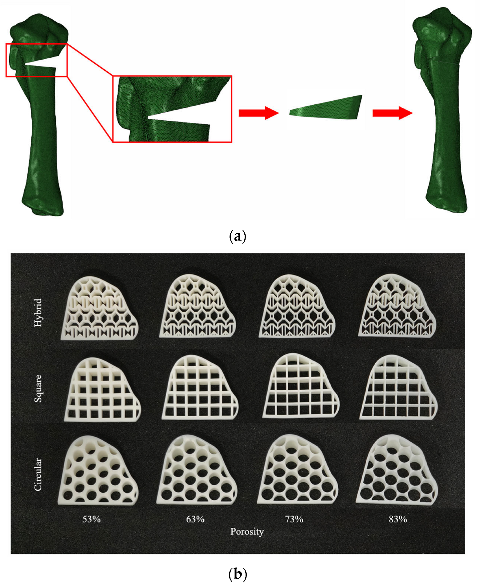
Figure 1. (a) Pig tibia sample; (b) tibial CT image; (c) tibial FE model; (d) tibial defect sample; (e) tibial defect model; (f) tibial defect FE model.
Applsci 15 06467 g001
Figure 2. (a) The establishment process of the postoperative tibial finite element model; (b) tibial implants with different porous structures and porosities.
Applsci 15 06467 g002
Figure 3. (a) Experimental equipment for mechanical testing coupled with 3D-DIC of the pig tibia model; (b) force–displacement curve of mechanical testing and FEA data of pig tibia model; tibial displacement field distribution by FEA simulation and DIC testing under different physiological activities: (c) standing; (d) walking; (e) jogging; (f) running.
Applsci 15 06467 g003
Figure 4. Tibial surface and cross-section stress field distribution by FEA simulation under different physiological activities: (a) standing; (b) walking; (c) jogging; (d) running. Tibial surface and cross-section strain field distribution by FEA simulation under different physiological activities: (e) standing; (f) walking; (g) jogging; (h) running. (i) Maximum equivalent stress values in the intact tibia under different physiological activities. (j) Maximum equivalent strain values in the intact tibia under different physiological activities.
Applsci 15 06467 g004
Figure 5. (a) Stress distribution in tibial models following implantation of tibial implants with varying structural configurations and porosity levels; (b) the maximum stress value on the tibia varies with the implantation of tibial implants with different porosities.
Applsci 15 06467 g005
Figure 6. (a) Stress distribution on tibial implants with varying structural configurations and porosity levels; (b) maximum stress values of tibial implants with different porosities as a function of porosity.
Applsci 15 06467 g006
Figure 7. (a) Displacement distribution on tibial implants with varying structural configurations and porosity levels; (b) maximum displacement values of tibial implants with different porosities as a function of porosity.
Applsci 15 06467 g007
Figure 8. Force–displacement curves of the tibia following implantation of porous tibial prostheses with varying porosity levels: (a) hybrid pore structure; (b) square pore structure; (c) circular pore structure. (d) Maximum displacement value of tibial compression test after HTO surgery.
Applsci 15 06467 g008
Table 1. Implant porosity parameter adjustment table.
Structure ParametersPorosity
53%63%73%83%
Hybrid hole strut size0.9 mm0.7 mm0.5 mm0.3 mm
Square hole diameter4.4 mm4.8 mm5.1 mm5.5 mm
Circular hole diameter5.4 mm5.8 mm6.3 mm6.7 mm
Table 2. Properties of bone materials.
MaterialsYoung’s Modulus (MPa)Poisson’s Ratio
Cortical bone17,0000.3
Cancellous bone4500.3
Resin27000.42
Table 3. Maximum stress value on the tibia after implantation of tibial implants with different porosities (unit: MPa).
StructurePorosity
53%63%73%83%
Hybrid22.1223.3424.2031.01
Square25.7128.6130.2431.50
Circular23.4027.8628.5832.99
Table 4. Maximum stress value on the tibial implants after implantation of tibial implants with different porosities (unit: MPa).
StructurePorosity
53%63%73%83%
Hybrid12.3313.6215.9520.69
Square16.6717.7623.3226.84
Circular14.4114.5518.0921.91
Table 5. Maximum displacement values of tibial implants with different porosities (unit: μm).
StructurePorosity
53%63%73%83%
Hybrid54.1355.4557.1561.47
Square55.7757.4659.5963.56
Circular55.7758.2059.6863.11
Disclaimer/Publisher’s Note: The statements, opinions and data contained in all publications are solely those of the individual author(s) and contributor(s) and not of MDPI and/or the editor(s). MDPI and/or the editor(s) disclaim responsibility for any injury to people or property resulting from any ideas, methods, instructions or products referred to in the content.

