Article

Techno-Economical Evaluation of Extractive Distillation Process for Isopropanol Dehydration with Different Extractive Solvents

by
Mihaela Neagu
* and
Diana-Luciana Cursaru
Department of Petroleum Refining and Environmental Engineering, Faculty of Petroleum Refining and Petrochemistry, Petroleum-Gas University of Ploiesti, 39, Bucuresti Blvd, 100680 Ploiesti, Romania
*
Author to whom correspondence should be addressed.
Appl. Sci. 2025, 15(12), 6430; https://doi.org/10.3390/app15126430
Submission received: 3 May 2025 / Revised: 2 June 2025 / Accepted: 5 June 2025 / Published: 7 June 2025

Abstract

:
In recent decades, the attention of researchers has been directed towards the study of the dehydration of isopropanol (IPA) through different techniques. Besides its multiple uses in the chemical industry, IPA is also a potential bio-component in eco-friendly gasolines. Extractive distillation is a successful technique for separating IPA from a minimum boiling azeotrope with water. However, the major challenge is the production of fuel-grade IPA (minimum 99.92 mol%) with low expenses. As a consequent step in the investigation of IPA dehydration with propylene glycol as extractive solvent, the present study compares its efficiency and economic viability with two other extractive solvents, namely ethylene glycol (EG) and dimethyl sulfoxide (DMSO). A systematic and comprehensive methodology was developed to design a three-column extractive distillation (TCED) for each investigated solvent. A techno-economic assessment of all the investigated processes concluded that ethylene glycol, followed by propylene glycol, seems to be the most promising solvent in the IPA dehydration process. Further, the heat integration of hot streams (SH flowsheets) demonstrated improvements over 17% in the case of ethylene glycol solvent, around 16% in the case of propylene glycol (PG) solvent, and only 10% (in the case of DMSO solvent) reduction in utility consumption, improving the energy efficiency of TCED processes. Furthermore, SH flowsheets yield a 14% cost saving obtained in terms of total annualized cost (TAC) and, respectively, 8.69%, by comparison with TCED processes. In the case of DMSO solvent, the TAC reduction is only 3.54% due to the capital cost, which has an increase of 3% mainly due to the high solvent cost.

1. Introduction

Extractive distillation (ED) is a reliable method employed for the separation and purification of azeotropic mixtures or mixtures characterized by low relative volatility [1]. In the process of ED, the relative volatility of these mixtures can be augmented by incorporating a selective extractive agent [2,3]. As a result, ED is capable of effectively separating alcohol–water azeotropic mixtures that are not separable through conventional distillation techniques.
Typically, the ED process comprises two primary components: an extractive distillation column (EDC) and a solvent recovery column (SRC). It is noteworthy that in specific instances involving ethanol/water, propanol/water, or butanol/water mixtures, water is present in excess within the fermentation broth. To minimize energy consumption and economic costs associated with the conventional extraction distillation (ED) process, excess water from the feed is removed using a preconcentration column (PC) before entering the extraction distillation column (EDC) [4]. This innovative approach, which incorporates a preconcentration column into the distillation process, is referred to as the TCED process [5]. This offers researchers the opportunity to design and explore processes in which the heat integration of the PC with the ED column or/and SRC could be achieved [5,6,7].
Europe is proposing that C2–C4 bio-alcohols play an increasingly important role in the formulation of advanced fuels as renewable energy for transport [8,9,10]. However, the production of these bio-alcohols must be ensured with the lowest possible energy consumption [11]. In the dehydration of these alcohols, the flexibility of the ED process in both design and operation has attracted the attention of researchers [12,13]. The essential step in the design of bio-alcohol dehydration processes by ED is the choice of the most suitable solvent for performing the separation. In addition to the selection of the solvent, for a well-designed ED process, it is very important to obtain the purities required by the process with low energy consumption and minimal solvent losses [14]. Moreover, identifying the most favorable operating parameters of the ED columns to meet the process constraints is a complex task and can only be achieved with the help of process simulators.
Our attention is focused on the dehydration of isopropyl alcohol (IPA) to obtain fuel grade. It is well known that the isopropanol (IPA)–water mixture forms a minimum-boiling azeotrope at 87.8 wt.% at 353.55 K, under atmospheric pressure. Therefore, a viable option for the dehydration of IPA is the ED process. Studies in recent decades have reported investigations into the dehydration of IPA by extractive distillation using ethylene glycol (EG) and dimethyl-sulfoxide (DMSO) as solvents [10].
Arifin and Chien [15] investigated the IPA dehydration process by extractive distillation with DMSO. The design and control of the process operating parameters were performed for a feed flow rate of 100 kmol/h, equimolar IPA/water binary, in a conventional ED process with EDCs and SRCs. The purpose of their investigation was to achieve 99.9999 mol% of IPA in the distillate flow of the EDC and 99.9 mol% of water in the distillate of the SRC. The ultrahigh purity in IPA is dictated by the usage of IPA in the semiconductor industry. Even though they demonstrated the feasibility of using DMSO as a solvent, the constraints related to the purity of IPA led to an ED process with a very high EDC, which would imply construction problems. Also, the authors report the need for high-pressure steam for both reboilers.
Duan and Li [1] demonstrated the feasibility of TCED process for IPA/water separation from 250 kmol/h feed flow rate with 28.6 mol% of IPA using DMSO as a solvent. Then, they studied several types of multi-effect heat integration and several types of solvent sensible heat recovery. Their final conclusion is that heat integration is a way to reduce the energy requirement of a TCED process.
Luyben [16] studied the IPA/water separation and purification with EG as solvent from a feed of 1875 kg/h of an 80 wt.% IPA and 20 wt.% water binary mixture, in the TCED process, with help from the Aspen Plus simulator. The purpose of this study was to develop a control structure of the main operational parameters in order to obtain an IPA concentration in the distillate of the EDC of 99.91 wt.%.
Kalla and co-authors [17] studied the feasibility of EG as an extractive agent for the separation of an equimolar IPA/water binary, from a 100 kmol/h feed flowrate. The authors developed a sensitivity analysis with help from the Aspen Plus simulator to depict the operating conditions of the EDC with the purpose of obtaining 99.974 mol% purity of IPA in the distillate flow of the EDC.
In our recent paper [18], the ability of a new proposed solvent, namely, propylene glycol (PG), for IPA dehydration by conventional three-column extractive distillation (TCED) was investigated. The optimal design of each column from the TCED process was developed by simulation using the PRO/II process simulator. The second part of our recent paper proposed four flowsheets of a multiple-heat integration process. With the lowest TAC as the goal, the energy and financial benefits of each suggested process were determined and examined.
In reviewing the literature studies on IPA dehydration by extractive distillation, it is observed that, in the past, only two solvents have been investigated, namely ethylene glycol (EG) and dimethyl sulfoxide (DMSO). However, no conclusion can be reached regarding their efficiency and economic viability, as the investigations were conducted for different flow rates and compositions of the IPA/water mixture feed. Until now, the design of the extractive distillation process and the control of the main operating parameters took into account different IPA purity targets obtained in two- or three-column processes. To overcome the differences between the approaches in the literature on extractive distillation for IPA dehydration, our study, as a novelty, was conducted to compare the efficiency and economic viability of three solvents for IPA dehydration, namely ethylene glycol (EG), dimethyl sulfoxide (DMSO), and propylene glycol (PG). Although PG is part of the glycolic solvent group along with EG, it has been previously studied [18] as an alternative that is more environmentally and human health-friendly, more biodegradable, and less volatile than its counterpart, EG. A systematic and comprehensive methodology was developed to design a three-column extractive distillation (TCED) with optimum design variables for a unique flowrate and feed composition and the same purity of IPA as the target. Moreover, an energy-saving flowsheet for sensible heat recovery from hot flows was also studied for the TCED process, with EG and DMSO as solvents. Finally, a comparison of the processes in terms of the total annualized cost (TAC) was made.

2. Methodology

This section explains the design methodology of the extractive distillation process for IPA/water separation with EG and DMSO as solvents, first in a conventional TCED flowsheet, then in heat integration (SH) flowsheets, and finally through their economic evaluation.

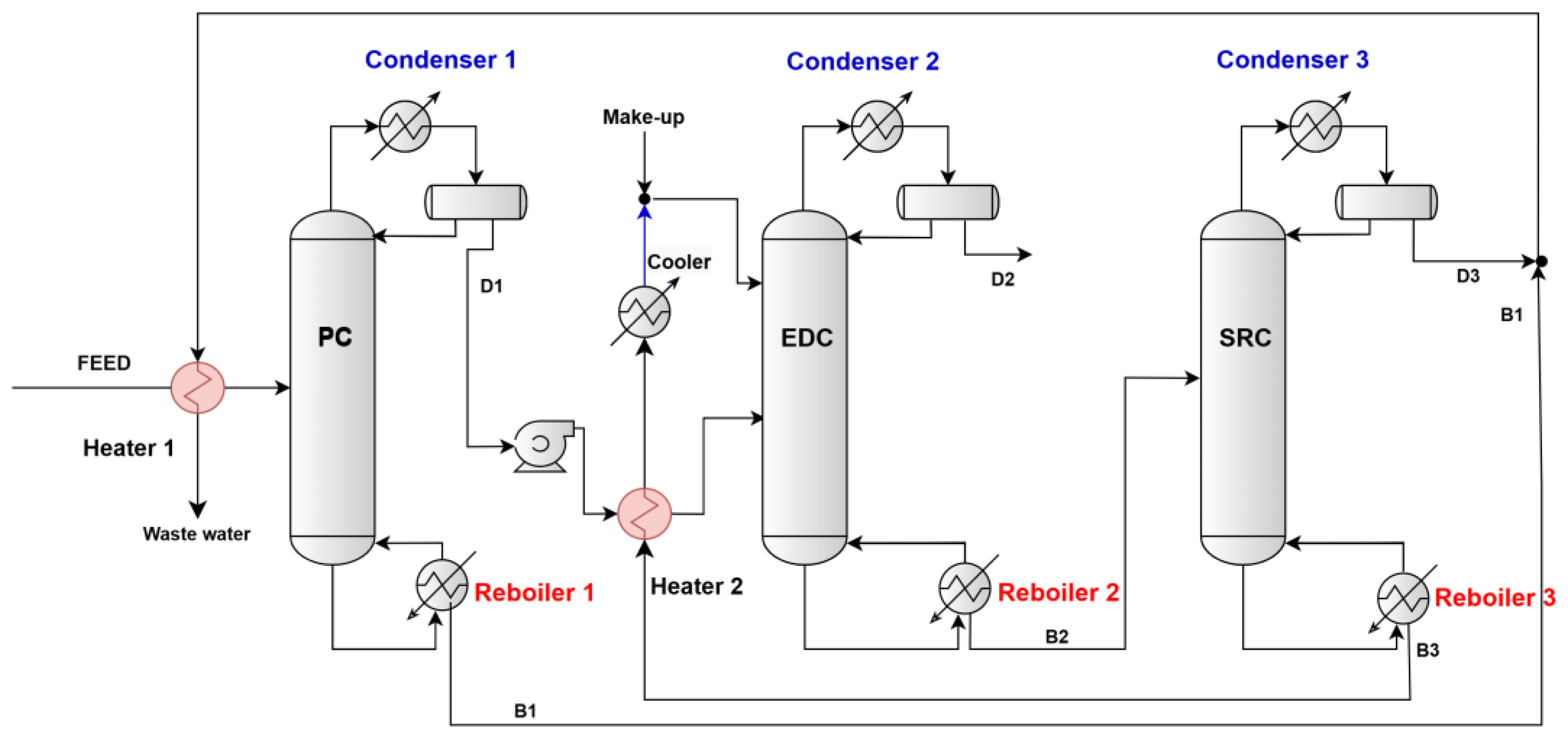
2.1. Separation Process Design TCED

A TCED process with a preconcentration column (PC), an extractive distillation column (EDC), and a solvent recovery column (SRC) was simulated in a steady state using the AVEVA PRO/II v.2024 software for IPA dehydration with EG and DMSO as solvents. The flowsheet of the IPA–water separation TCED process is depicted in Figure 1.
The same flowsheet illustrated in Figure 1 was utilized for the IPA/water separation in our previous paper [18]. In summary, the primary column (PC) is a conventional distillation column that removes most of the water from the feed as the bottom product (B1) while separating the IPA/water minimum-boiling azeotrope mixture as the distillate product (D1). The D1 flow is directed to the lower section of the extractive distillation column (EDC), while ethylene glycol (EG) or dimethyl sulfoxide (DMSO) solvents are introduced at the top section of the column. The distillate product from the EDC (D2) is anhydrous IPA, and the bottom flow (B2) contains a mixture of solvent and water. In the solvent recovery column (SRC), the solvent is recovered as the bottom product stream (B3) and is then recycled to the EDC after cooling. The distillate flow from the SRC (D3) is water with minimal IPA loss. All columns operated at atmospheric pressure, and their feeds were in the liquid state at bubble-point temperatures.
In these simulations, a Non-Random Two-Liquid (NRTL) model coupled with the UNIFAC fluid package was selected to simulate the thermodynamic IPA/water/EG and IPA/water/DMSO systems [19]. Table S1 in the Supporting Information file shows the binary interaction parameters of the above systems from AVEVA PRO/II v.2024. The INSIDE-OUT mathematical algorithm incorporated in the simulator was used to solve the mass and energy balance, and the outputs results were used for equipment design and then to evaluate the total capital cost and operating cost.

2.2. Sensible Heat Recovery from the Hot Streams

As illustrated in Figure 1, the regenerated, high-temperature solvent stream B3 needs to be cooled before being recirculated to the EDC. This flow exhibits a high temperature, which corresponds to the boiling point of each solvent at the pressure found at the bottom of the SRC. The sensible heat of these solvents is utilized to preheat the EDC. By capitalizing on the sensible heat of each solvent, we expect to reduce the duty on the EDC’ reboiler, thereby decreasing steam consumption. The D3 distillate flow from the SRC is mostly composed of high-temperature water, which corresponds to the boiling temperature of the mixture at the pressure in the SRC reflux vessel. And flow B1 at the bottom of the PC is predominantly made up of water with a temperature higher than that of D3 (corresponding to the boiling temperature of the mixture at the pressure at the bottom of the PC). Both streams must be cooled before being discharged to the wastewater treatment plant. This presents an opportunity to utilize this waste heat to preheat the PC feed. As a result, the duty on the PC reboiler is reduced, which decreases the need for steam at the reboiler. These proposals to valorize the heat from the hot streams are represented in Figure 2.

2.3. Economic Evaluation

The total annual cost (TAC) was calculated from
TAC = TACC/payback periods + TAEC
where TACC is the total annual capital cost with 3-year payback periods, and TAEC is the total annual energy cost.
In this paper, only columns, reboilers, condensers, and other heat exchangers are considered for TACC calculations. Due to the small impact of the costs of pumps, reflux vessels, and pipes, these will not be taken into account at this stage of the preliminary design. It is obvious that all of them will be added to the detailed design of the installations. The diameters of the columns equipped, all with the same type of valve trays, are calculated automatically by simulation by calling the “tray sizing” function in AVEVA PRO/II v.2024.
Operating costs (TAEC) include steam costs for reboilers and cooling water costs for condensers and coolers. The cost of solvent make-up is not taken into account, being negligible [14]. The column reboilers use low-pressure steam at the PC, medium-pressure steam at the EDC, and high-pressure steam at the SRC. The cooling water for all condensers and the cooler enter at a temperature of 305.15 K and leave at a temperature of 325.15 K. Table S2 in the Supporting Information file shows the different formulas for equipment costs calculation, the utility prices, and solvent prices.
The distance between the trays for each column was set at 0.6 m. The calculation of the heat transfer areas was based on the overall heat transfer coefficient and the log-mean temperature differences (LMTDs) for each heat exchanger. The overall heat transfer coefficients were referenced from [16], while the LMTD values were calculated using AVEVA PRO/II v.2024 software for each heat exchanger.
The cost of the solvent for the initial charge varies depending on the type of solvent and its purity. We chose Carl Roth GmbH as the supplier, and the purity of all solvents was set at 99.5%. The operating time was 8000 h per year. All cost correlations used in this evaluation, taken from [20], were updated to reflect the Marshall and Swift cost index (M&S) value for the year 2020 during the calculation of the total annual capital cost (TACC).

3. Results and Discussions

As mentioned previously in the Section 1, one of the objectives lies in presenting a detailed techno-economic comparison of conventional proposed TCED processes for IPA dehydration with ethylene glycol (EG), dimethyl sulfoxide (DMSO), and propylene glycol (PG) as solvents. After systematically establishing the optimal operating parameters of each column, a new heat-integrated process (SH) was proposed for heat saving from water hot flows and hot solvents. All processes are finally compared based on key performance indicators, namely, TAC. The key to comparing processes is to establish the same feed flow as the PC and the same targets (flow purities) to achieve.

3.1. Design of the Conventional TCED Process

The feed flow rate of the PC was assumed at 200 kmol/h at 313.15 K and 113.48 kPa. The feed composition was defined as 54.5 mol% IPA and 45.5 mol% water, as reported in the literature [16,21]. All operating data of the PC reported in our previous work were kept the same [18]. From the beginning, for the design process of the PC, the distillate (D1) composition was specified at 65.19 mol% IPA (meaning a near-azeotropic composition mixture of IPA/water) at 111.46 kPa and 355.86 K. To reduce the IPA loss, the bottom composition was specified to be 99.997 mol% water, at 131.72 kPa and 380.7 K.
Distillate flow D1 (IPA/water minimum-boiling azeotrope mixture) feeds EDC. The EDC design is much more complicated because the solvent flow rate is an important design variable without which we cannot obtain the desired purity of the D2 distillate, meaning at least 99.92 mol% IPA. But other variables must also be optimized: the number of stages, the position of the feed stage, the position of the solvent feed stage, and the column reflux ratio. The solvent feed temperature to the EDC is maintained constant at 348.15 K, as suggested by Knight and Doherty [22]. The EDC operated at a 101.3 kPa condenser pressure and a column pressure drop of 20.3 kPa.
The iterative procedure for obtaining the optimal design and operation parameters of the EDC is the following:
  • The number of trays in the EDC, labeled as NT2, was set at 20, following AVEVA PRO/II’s notation of numbering from top to bottom. The feed tray, referred to as NF2, was fixed at 16, while the feed tray for the extractive solvent, labeled NFE, was fixed at 5. Additionally, the reflux molar ratio (RR2) was set at 0.9. The molar ratio of the extractive solvent to feed (E/D1) was varied from 0.5:1.0 to 2.0:1.0 for the EG solvent and from 0.25:1.0 to 1.0:1.0 for the DMSO solvent. The results of the changing effect of the E/D1 ratio over the IPA and solvent concentration in D2 are reported in Figure 3a,b. The increase in the solvent ratio significantly impacts the purity of the D2 product from the top of the column. While it raises the IPA concentration in the D2 stream, which is desired, it also results in a higher concentration of solvent in that stream. Therefore, selecting the optimal solvent ratio involves balancing the IPA concentration with the solvent concentration. We will also examine additional parameters to ensure the overall quality of the D2 distilled product. In the case of EG solvent, the most proper IPA concentration in D2 is only 99.8 mol% but with a very small loss of EG in D2 (i.e., 0.74 ppm), which was depicted for the E/D1 value of 1.25/1, and in the case of DMSO solvent, there was an IPA concentration in D2 over the target (i.e., 99.93 mol%) but with an unacceptable loss of DMSO (i.e., 30.98 ppm) in D2, which was depicted for the E/D1 value of 0.8/1.
  • At an optimal solvent ratio (i.e., E/D1 at 1.25/1.0 for EG and E/D1 value of 0.8/1 for DMSO), the number of trays in EDCs changes from 20 to 26 trays in the EDC with EG and from 19 to 24 trays in the EDC with DMSO. All the other parameters remain unchanged. The number of trays in the EDCs affects both the height of the column and the investment costs. Generally, columns with fewer trays require a lower initial investment. However, the choice of the optimal number of trays should primarily focus on ensuring the quality of the D2 distilled product. Figure 4a,b show that at 22 optimal trays in the EDC with EG solvent, the IPA concentration in D2 was 99.91 mol% (very close to the target of 99.92 mol%) and with a very small loss of EG in D2 (i.e., 0.74 ppm). In the case of DMSO solvent, the optimal number of trays in the EDC was established at 23 because the loss of solvent was a little bit lower (i.e., 30.84 ppm), while the IPA concentration was 99.94 mol%. The number of trays in the EDC has minimal impact on the DMSO concentration in D2.
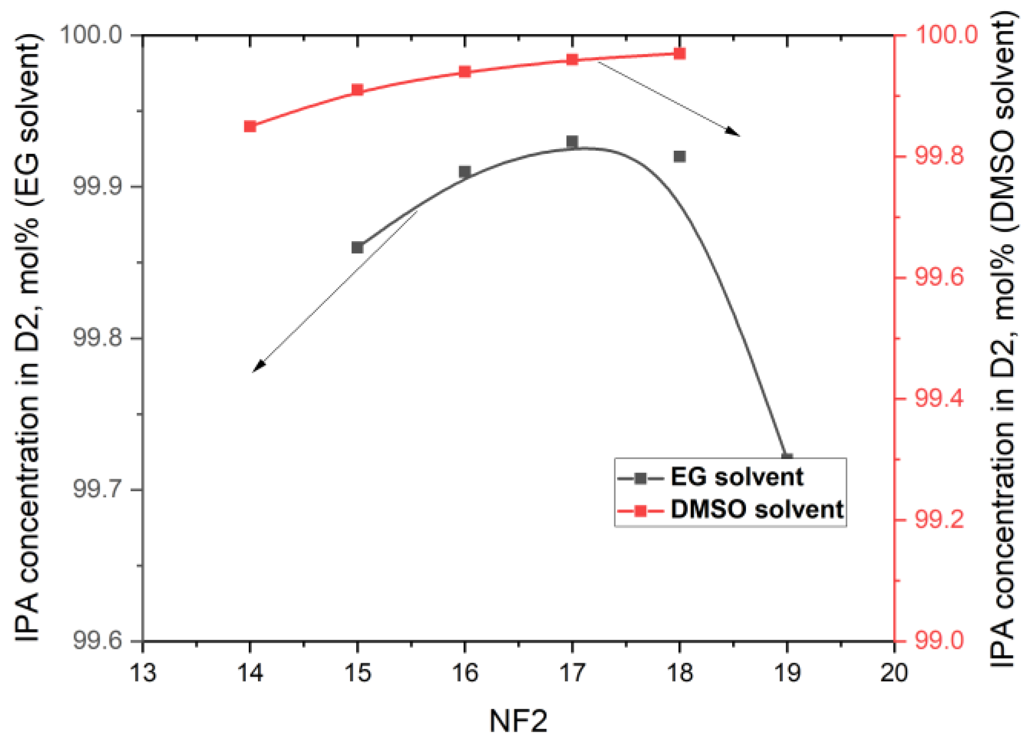
  • The next step in our simulations was to study the effect of the feed tray (NF2) position on the target concentrations. All the other parameters remain unchanged. For the EDC with EG, the range of the feed tray position was in the range of 15 to 19, and for the EDC with DMSO, in the range of 14 to 18. The position of NF2 has very little influence on the concentrations of IPA and/or solvents in D2, as illustrated in Figure 5. Lowering the feed from tray 16 to tray 17 leads to an increase in the IPA concentration in D2 from 99.91 mol% to 99.93 mol% in the EDC with EG and from 99.94 mol% to 99.96 mol% in the EDC with DMSO. A significant decrease in DMSO concentration in D2 was not expected.
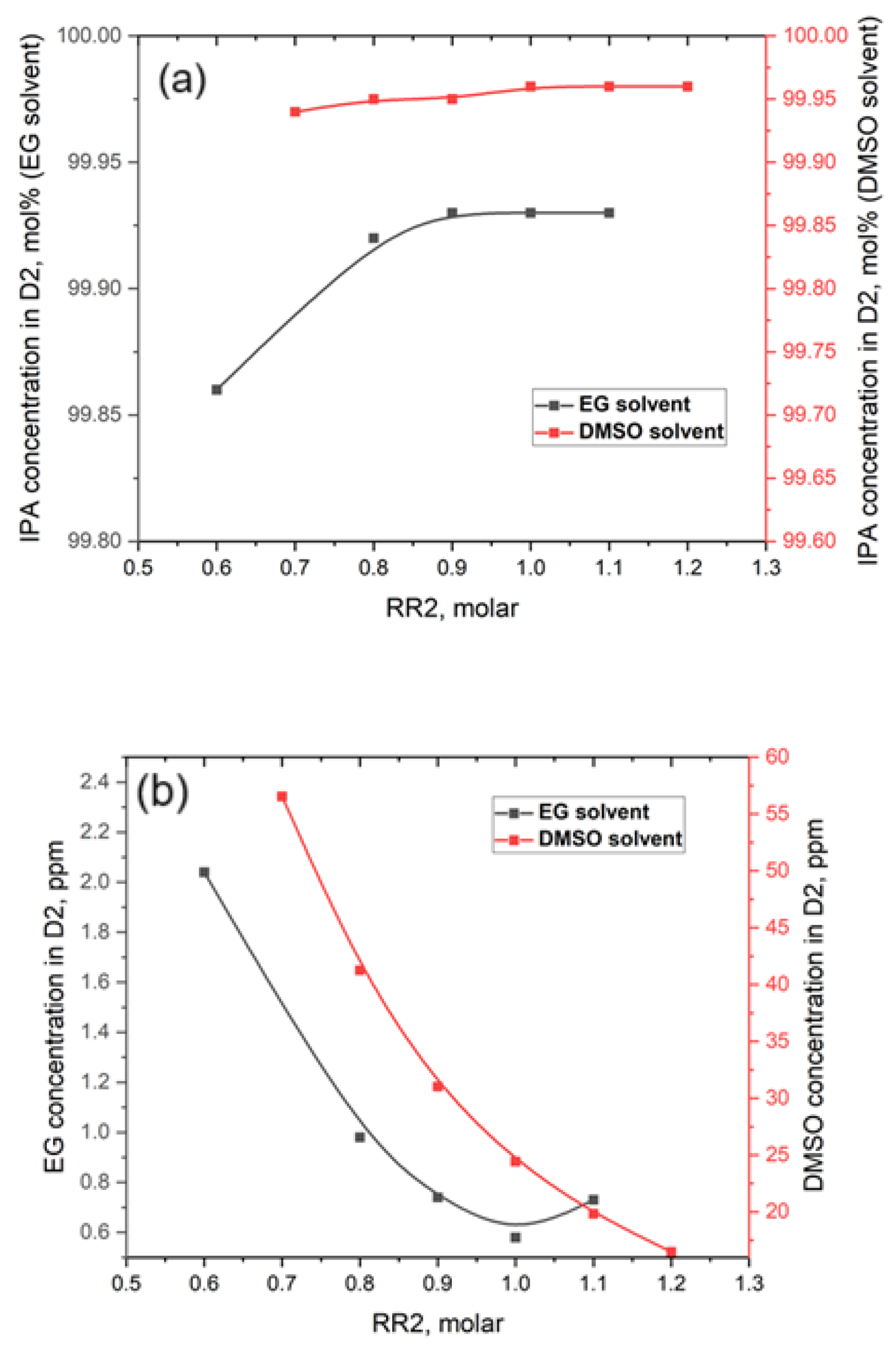
  • We expect the reflux ratio (RR2) to have a significant contribution to the separation. Also, the reflux ratio plays a crucial role in the overall TCED process, affecting both the diameter and investment costs of the EDCs. It also impacts the thermal duty of the condensers and reboilers, along with their associated utility consumption. Ideally, the reflux ratio should be kept as low as possible to minimize both investment and operating costs. However, the most important factor in determining the optimal ratio is the quality of the D2 distilled product. The investigation range of RR2 was 0.6 to 1.1 in the EDC with EG and in the range of 0.7 to 1.2 in the EDC with DMSO. As can be seen from Figure 6a,b, the increase in RR2 values leads to a slight increase in IPA concentration but also to an expected decrease in DMSO concentration. So, in taking into account the targets of concentrations in D2, it can be concluded that an RR2 value of 1.1 provides an IPA concentration of 99.93 mol% and an EG concentration of 0.47 ppm. In the case of DMSO solvent, for an RR2 of 1.2, the IPA concentration of 99.96 mol% is very satisfactory, but the DMSO at 16.5 ppm is still very high.
  • The last step in our iterative procedure refers to the feed tray position of solvent (NFE). This investigation was conducted only for the case of an EDC with DMSO. Lowering the NFE for DMSO by a single tray (from 5 to 6) has a pronounced impact on the decrease in DMSO concentration from 16.5 ppm to below 2 ppm (i.e., 1.57 ppm). A small decrease in IPA concentration was depicted (i.e., from 99.96 mol% to 99.94 mol%).
The iterative procedure led to the identification of the most favorable operating parameters of the EDC:
For the EG solvent, set the solvent ratio E/D1 at 1.25/1.0, NT2 at 22, NF2 at 17, NFE = 5, and RR2 = 1.1.
For the DMSO solvent, set the solvent ratio E/D1 at 0.8/1.0, NT2 at 23, NF2 at 17, NFE = 6, and RR2 = 1.2.
The detailed parameters of the EDC for the EG and DMSO solvents investigated in this work in comparison with the PG solvent investigated in our previous work are shown in Table 1. For all solvents investigated, it is observed that the IPA purity in the D2 distillate is at least 99.92 mol%, but this is achieved with a much higher PG flow rate than in the case of the other two solvents. This results in an increase in the reflux ratio and column diameter, as well as higher reboiler and condenser duties and larger heat exchanger areas.
Following the iterative optimization of the EDC and the selection of the optimal parameters, one can continue the work on optimizing the solvent regeneration columns. In the next step of our study, many variants were simulated for each solvent in order to depict the optimal design and operation parameters of the SRC. The target of the simulations of these columns is that in the D3 distillate, the solvent concentration should be a maximum of 2 ppm, but also the IPA concentration should be as low as possible. These specifications are desired because the D3 distillate is predominantly water. It is recommended that the D3 stream, together with the B1 stream, after cooling, be sent to a wastewater treatment plant [21]. Moreover, it is very important to find design and operating parameters with which to obtain very well-regenerated solvents, i.e., with a maximum water concentration of 5 ppm. This is because, after cooling, the solvent is recirculated to the top zone of the EDC. The SRC pressure is 101.3 kPa (in reflux drum) and 370.7 K, and the column pressure drop is 5 kPa.
An iterative procedure for obtaining the optimal design and operation parameters and the SRC was developed, which is as follows:
  • The feed tray (NF3) was fixed at 7, and the reflux molar ratio (RR3) was fixed at 1.5 for the SRCs. The number of trays in the SRCs was changed from 13 to 17 trays in the EDC for both EG and DMSO solvents. The results of the changing effect of the number of trays (NT3) over the IPA and solvent concentration in D3 are reported in Figure 7. The increase in NT3 leads to a significant reduction in the solvent concentration in the D3 water stream. The reduction is substantial in the case of DMSO, from 383,000 ppm (38.30 mol%) for 13 trays in the SRC to only 0.008 ppm for 17 trays in the SRC. Regarding the EG concentration in D3, it is 0.53 ppm for 13 trays and 0.0022 ppm for 17 trays in the SRC. It is observed that the number of trays in the SRC has minimal impact on IPA concentration in D3, which reaches a maximum of 0.51 mol% in both cases studied. The optimum number of trays for the EG recovery column was selected to be 15, and for the DMSO recovery column, it was selected to be 16.
  • The position of the feed tray on the composition of the D3 distillate is not notable. For these reasons, NF3 remains at 7.
  • However, the reflux ratio (RR3) has considerable effects on the separation in the SRC. The investigation range of RR3 was 0.4 to 1.5 in the EG regeneration column and in the range of 0.8 to 1.5 in the SRC for DMSO. As can be seen from Figure 8, the increase in RR3 values leads to a drastic decrease in solvent concentration in water D3 flow. It can be concluded that an RR3 value of 0.6 results in an EG concentration of 1.2 ppm and an IPA concentration of 5133 ppm. In the case of DMSO solvent, its concentration in D3 for an RR3 of 1.4 is 1.04 ppm, and the IPA concentration is 5132 ppm.
After carrying out the iterative procedure, the most favorable operating parameters of the regeneration column SRC for the investigated solvents were identified:
For EG solvent regeneration, the EG concentration in water flux D3 at 1.2 ppm and IPA concentration of 5133 ppm was depicted at an NT3 of 15, NF3 at 7, and RR3 at 0.6.
For DMSO solvent regeneration, the DMSO concentration in water flux D3 at 1.04 ppm and IPA concentration of 5132 ppm was depicted at an NT3 of 16, NF3 at 7, and RR3 at 1.4.
Table 2 provides details on the operating parameters of the regeneration columns of the two solvents investigated in this work compared to the PG solvent investigated in our previous work. For all SRCs investigated, it is observed that each solvent was very deeply regenerated (only 5 ppm water remains in the solvents). But in the water D3 distillate flow, the IPA loss is 5132 ppm concentration. Only the regeneration column of PG seems to offer an advantage in this regard because the IPA loss is only 1050 ppm.

3.2. Design of TCED Energy-Saving Processes

As shown in Figure 2, two possibilities were identified for the heat recovery of the sensible heat from hot streams. The D3 water at 372.62 K can be mixed with B1 hot water at 380.7 K. Then, the resulting hot flow at 91.21 kmol/h and at 372.85 K, in Heater 1, could preheat the PC feed from 313.15 K to 327.10 K. In this context, the duty of Reboiler 1 (reboiler of PC) decreases from 3407 kWh to 3309 kWh, and its area decreases from 116 m2 to 113 m2. In other words, it was found that the energy saving for Reboiler 1 was around 2.9%. After Heater 1, the hot water stream reduces its temperature from 380.7 K to 323.15 K and can be directed towards a wastewater treatment plant.
Also, in Figure 2, it can be observed that, in Heater 2, the sensible heat of the B3 hot solvent was recovered to preheat the EDC feed. The liquid feed (D1 flow at bubble point) can be partially vaporized. It is well known that a column with a partially vaporized feed will have a lower reboiler duty than a column with a boiling liquid feed. The results presented in Table 3 confirm the energy saving at the PC reboiler and the EDC reboiler by exploiting the sensible heat of the hot streams mentioned above. Moreover, the duty and area of the cooler will also decrease considerably.

3.3. Economic Performance Comparison of TCED Processes

In this section, the capital cost, utilities cost, and TAC for the three solvents will be compared. Table 4 presents these results for the conventional extractive distillation systems (TCED) and the hot stream heat recovery designs (SH-TCEDs).
It is shown that in the case of DMSO solvent, the flowsheet with heat recovery from hot streams (SH1) does not lead to a reduction in capital cost because the flow rate and temperature of the solvent stream are the lowest compared to for the other solvents. This is reflected in a smaller reduction in the EDC reboiler’s duty, steam consumption, and its area (see Table 3). Therefore, the effect of heat recovery from the hot DMSO solvent does not compensate for the cost of the new Heater 1 and Heater 2 of the SH flowsheet. The energy saving is only 10.45%, and the TAC decreases by only 3.54%. So, the two glycols (i.e., EG and PG) are still considered competitors from our point of view. The results from Table 1, Table 2 and Table 3 support those in Table 4, namely, EG as an extractive distillation solvent in IPA dehydration has more advantages than using PG as a solvent. The capital cost is reduced by 10.79%, the utility cost is reduced by 17.03%, and the total TAC is reduced by 13.95% when using EG as a solvent in the SH scheme compared to the conventional TCED. Even if we compare only conventional TCED, it still turns out that DMSO has higher capital, utilities, and TACs than EG.
For the same economic factors, PG solvent indicates higher costs because its flow rate is much higher than that of the other two solvents. PG possesses several advantages, including lower toxicity to human and animal health compared to EG [23,24]; it is biodegradable [25,26] and has lower cost than EG, and the extractive distillation dehydration process offers more possibilities for full heat integration for the recovery of heat from the hot solvent stream, as shown our previous work [18].

4. Conclusions

This paper presented a unique comparison between the separation and economic performances of EG, DMSO, and PG as extractive distillation solvents for IPA dehydration from its azeotrope with water. A conventional three-column extractive distillation (TCED) process was selected for comparison. The aim was to obtain the optimal operating and design parameters of the EDCs, which offer a distillate product with a minimum of 99.92 mol% IPA. For the SRC, the aim was to obtain very well-regenerated solvents (with only 5 ppm water), but also a water flow (as distillate) with a loss below 2 ppm solvent. We mention that the entire TCED process for the PG solvent case was carried out in a previous study [18], and the data obtained were used for comparison with the EG and DMSO solvents. Also, the optimal operating parameters of the PC are common to the three investigated cases and are those previously obtained.
In the second part of the work, the possibility of saving sensible heat from hot water streams (from the PC bottom flow and the distillate flow from the SRC) as well as the sensible heat of hot solvents was investigated. The proposed thermal integration process was assigned the SH flowsheet. The results of the economic evaluation show that both the TCED flowsheet and the improved SH flowsheet do not bring satisfactory results in the case of the DMSO solvent. Ethylene glycol seems to be a solvent with good results in the dehydration of IPA, which can reduce total annual costs by 13.95%, in the case of the heat integration process (SH) compared to the conventional TCED flowsheet. However, EG has a serious disadvantage: it is very toxic to human and animal health, pollutes the environment, is non-biodegradable, and has a high obtainment cost. All these disadvantages are overcome by PG.
Consequently, the selection of propylene glycol (PG) or ethylene glycol (EG) as a solvent for the extractive distillation process in the dehydration of isopropyl alcohol (IPA) is left to the discretion of the developer.

Supplementary Materials

The following supporting information can be downloaded at https://www.mdpi.com/article/10.3390/app15126430/s1, Table S1. Binary interaction parameters of the NRTL thermodynamic systems. Table S2. Formulas and data utilized for the economic evaluation.

Author Contributions

Conceptualization, M.N.; methodology, M.N.; software, M.N.; validation, D.-L.C.; formal analysis, D.-L.C.; investigation, M.N.; resources, M.N.; data curation, M.N.; writing—original draft preparation, M.N.; writing—review and editing, D.-L.C.; visualization, M.N.; supervision, D.-L.C. All authors have read and agreed to the published version of the manuscript.

Funding

This research received no external funding.

Institutional Review Board Statement

Not applicable.

Informed Consent Statement

Not applicable.

Data Availability Statement

The original contributions presented in this study are included in the article. Further inquiries can be directed to the corresponding author.

Conflicts of Interest

The authors declare no conflicts of interest.

Nomenclature

Abbreviations
DMSOdimethyl sulfoxide
EGethylene glycol
EDextractive distillation
IPAisopropanol
PGPropylene glycol
TCEDthree-column extractive distillation
LMTDslog-mean temperature differences
SHflowsheet for energy-saving process by sensible heat recovery of hot streams
NRTLnon-random two-liquid
UNIFACuniversal quasi-chemical
TACCtotal annual capital costs (USD/y)
TAECtotal annual energy costs (USD/y)
TACtotal annual cost (USD/y)
Symbols
PCpreconcentration column
EDCextractive distillation column
SRCsolvent recovery column
Bnbottom product for column n (kmol/h)
Dndistillate product for column n (kmol/h)
NF1feeding location for the fresh feed
NF2feeding location for the feed to column EDC
NF3feeding location for the feed to column SRC
NFEfeeding location for the solvent
NTnnumber of trays for column n
RRnreflux ratio for column n
Condenserncondenser duty for column n (kW)
Reboilernreboiler duty for column n (kW)
Coolercooler duty (kW)

References

  1. Duan, C.; Li, C. Energy-saving improvement of heat integration for separating dilute azeotropic components in extractive distillation. Energy 2023, 263, 125821. [Google Scholar] [CrossRef]
  2. Zhong, J.; Cheng, H.; Dai, Y.; Jiao, Y.; Wang, K.; Xin, L.; Zhang, Y.; Zhu, Z.; Cui, P.; Lu, Y.; et al. Design and multiple performance evaluation of green sustainable process for azeotropes separation via extractive distillation. ACS Sustain. Chem. Eng. 2023, 11, 16849–16881. [Google Scholar] [CrossRef]
  3. Pan, J.; Li, J.; Xu, Z.; Wu, H.; Ye, Q. Economic, thermodynamic and environmental analysis of separating high-concentration azeotropic mixture by a novel extractive dividing wall column configuration combining preconcentration and extractive distillation based on multi-objective optimization. Energy 2025, 319, 134935. [Google Scholar] [CrossRef]
  4. Wang, C.; Zhuang, Y.; Dong, Y.; Liu, L.; Zhang, L.; Du, J. Conceptual design of sustainable extractive distillation processes combining preconcentration and extractive distillation functions for separating ternary multi-azeotropic mixture. Chem. Eng. Sci. 2022, 263, 118088. [Google Scholar] [CrossRef]
  5. Wu, Q.; Wang, Z.; Xu, W.; Xin, L.; Hu, R.; Zhu, Z.; Wang, Y.; Cui, P. Innovative extractive distillation process combining preconcentration and solvent recovery functions for efficiently separating diisopropyl ether/isopropanol/water. Sep. Purif. Technol. 2025, 360, 131021. [Google Scholar] [CrossRef]
  6. Wang, Z.; Xin, L.; Wang, Y.; Wu, Q.; Xu, W.; Zhu, Z.; Wang, Y.; Cui, P. Optimization and dynamic control of green energy-saving process for azeotropes separation by mixed solvent extractive distillation. Renew. Sustain. Energy Rev. 2025, 218, 115813. [Google Scholar] [CrossRef]
  7. Duan, C.; Li, C. Energy-saving improvement of heat integration for separating dilute azeotropic components in extractive distillation: Part II-process integration. Sep. Purif. Technol. 2025, 360, 131009. [Google Scholar] [CrossRef]
  8. Belinchón, A.; Navarro, P.; Rubias, A.; Santiago, R.; Hernández, E.; Palomar, J. Extractive distillation for separating short-chain alcohols from water using cyclic carbonates as an extractive solvent: Experimental and process simulation. Sep. Purif. Technol. 2025, 370, 133283. [Google Scholar] [CrossRef]
  9. Hegely, L.; Nemeth, B.; Lang, P. Isopropanol dehydration by batch extractive distillation under variable pressure. Sep. Purif. Technol. 2025, 369, 133178. [Google Scholar] [CrossRef]
  10. Spatolisano, E.; Pellegrini, L.A. Dehydration of IPA-H2O mixture: Review of fundamentals and proposal of novel energy-efficient separation schemes. Chem. Eng. Sci. 2023, 273, 118672. [Google Scholar] [CrossRef]
  11. Thi, H.T.D.; Toth, A.J. Environment-Oriented Assessment of Hybrid Methods for Separation of N-Propanol–Water Mixtures: Combination of Distillation and Hydrophilic Pervaporation Processes. Membranes 2025, 15, 48. [Google Scholar] [CrossRef]
  12. Dongmin, H.; Chen, Y.; Shi, D. Different extractive distillation processes for isopropanol dehydration using low transition temperature mixtures as entrainers. Chem. Eng. Process. 2022, 178, 109049. [Google Scholar] [CrossRef]
  13. Lo, K.-M.; Chien, I.-L. Efficient separation method for tert -butanol dehydration via extractive distillation. J. Taiwan Inst. Chem. Eng. 2017, 73, 27–36. [Google Scholar] [CrossRef]
  14. Aniya, V.; De, D.; Singh, A.; Satyavathi, B. Design and operation of extractive distillation systems using different class of entrainers for the production of fuel grade tert-butyl alcohol: A techno-economic assessment. Energy 2018, 144, 1013–1025. [Google Scholar] [CrossRef]
  15. Arifin, S.; Chien, I.-L. Design and Control of an Isopropyl Alcohol Dehydration Process via Extractive Distillation Using Dimethyl Sulfoxide as an Entrainer. Ind. Eng. Chem. Res. 2008, 47, 790–803. [Google Scholar] [CrossRef]
  16. Luyben, W.L. Plantwide control of an isopropyl alcohol dehydration process. AIChE J. 2006, 52, 2290–2296. [Google Scholar] [CrossRef]
  17. Kalla, S.; Upadhyaya, S.; Singh, K.; Dohare, R.K.; Agarwal, M. A case study on separation of IPA-water mixture by extractive distillation using aspen plus. Int. J. Adv. Technol. Eng. Explor. 2016, 3, 187–193. [Google Scholar] [CrossRef]
  18. Nicolae, M.; Neagu, M.; Cursaru, D.-L. Energy-Saving Extractive Distillation Process for Isopropanol Dehydration with Propylene Glycol as Novel Extractive Solvent. Appl. Sci. 2024, 14, 9420. [Google Scholar] [CrossRef]
  19. Prausnitz, J.; Lichtenthaler, R.; de Azevedo, E.G. Molecular Thermodynamics of Fluid-Phase Equilibria, 3rd ed.; Prentice-Hall International Series in the Physical and Chemical Engineering Sciences; Prentice Hall PTR: Upper Saddle River, NJ, USA, 1999. [Google Scholar]
  20. Cui, Y.; Zhang, Z.; Shi, X.; Guang, C.; Gao, J. Triple-column side-stream extractive distillation optimization via simulated annealing for the benzene/isopropanol/water separation. Sep. Purif. Technol. 2020, 236, 116303. [Google Scholar] [CrossRef]
  21. Sommer, S.; Melin, T. Design and Optimization of Hybrid Separation Processes for the Dehydration of 2-Propanol and Other Organics. Ind. Eng. Chem. Res. 2004, 43, 5248–5259. [Google Scholar] [CrossRef]
  22. Knight, J.R.; Doherty, M.F. Optimal design and synthesis of homogeneous azeotropic distillation sequences. Ind. Eng. Chem. Res. 1989, 28, 564–572. [Google Scholar] [CrossRef]
  23. Qi, K.; Li, Z.; Zhang, C.; Tan, X.; Wan, C.; Liu, X.; Wang, L.; Lee, D.-J. Biodegradation of real industrial wastewater containing ethylene glycol by using aerobic granular sludge in a continuous-flow reactor: Performance and resistance mechanism. Biochem. Eng. J. 2020, 161, 107711. [Google Scholar] [CrossRef]
  24. Staples, C.; Williams, J.; Craig, G.; Roberts, K. Fate, Effects and potential environmental risks of ethylene glycol: A review. Chemosphere 2001, 43, 377–383. [Google Scholar] [CrossRef]
  25. Bielefeldt, A.; Illangasekare, T.; Uttecht, M.; LaPlante, R. Biodegradation of propylene glycol and associated hydrodynamic effects in sand. Water Res. 2002, 36, 1707–1714. [Google Scholar] [CrossRef] [PubMed]
  26. West, R.; Banton, M.; Hu, J.; Klapacz, J. The distribution, fate, and effects of propylene glycol substances in the environment. Rev. Environ. Contam. Toxicol. 2014, 232, 107–138. [Google Scholar] [CrossRef]
Figure 1. TCED process for IPA dehydration.
Applsci 15 06430 g001
Figure 2. The proposed flowsheet for sensible heat recovery from the hot streams.
Applsci 15 06430 g002
Figure 3. Effect of solvent ratio E/D1 over (a) IPA concentration in D2 and (b) solvent concentration in D2.
Applsci 15 06430 g003
Figure 4. Effect of tray number on EDC (NT2) over (a) IPA concentration in D2 and (b) solvent concentration in D2.
Applsci 15 06430 g004
Figure 5. The influence of NF2 over IPA concentration in D2.
Applsci 15 06430 g005
Figure 6. Effect of reflux ratio in EDC (RR2) over (a) IPA concentration in D2 and (b) solvent concentration in D2.
Applsci 15 06430 g006
Figure 7. Effect of tray number (NT3) in SRC over solvent concentration in D3.
Applsci 15 06430 g007
Figure 8. Effect of reflux ratio (RR3) in SRC over solvent concentration in D3.
Applsci 15 06430 g008
Table 1. Detailed design parameters of the EDCs.
ParametersEDC with PG Solvent *EDC with EG SolventEDC with DMSO Solvent
D2 flowratekmol/h109.07108.79108.76
kg/h6551.476534.056533.55
D2 compositionmolarIPA99.9299.9399.94
Water807 ppm706.4 ppm600 ppm
Solvent5.5 ppm0.47 ppm1.57 ppm
B2 flowratekmol/h628.32267.43192.21
kg/h44,416.1214,037.3111,517.24
B2 compositionmolarSolvent90.6978.1569.59
Water9.3021.7430.25
IPA97.7 ppm1121 ppm1560 ppm
NT2302223
NF2201717
NS2556
RR21.51.11.2
Condenser 2, dutykWh299925122631
Condenser 2, aream286.7072.3076.02
Water consumption to condenser 2 (a)kg/h128,899.085107,979.57113,108.26
Reboiler 2, dutykWh663934313205
Reboiler 2, aream2344.55120111.71
Steam consumption to reboiler 2 (b)kg/h12,11862625849
Diameterm1.5241.2191.219
* All data are from previous work [18]. (a) Inlet water temperature of 305.15 K, exit water temperature of 325.15 K. (b) Saturated steam at 1300 kPa.
Table 2. Detailed design parameters of the SRCs.
ParametersSRC with PG Solvent *SRC with EG SolventSRC with DMSO Solvent
D3 flowratekmol/h58.5158.4258.44
kg/h1056.681065.001065.52
D3 compositionmolarWater99.8999.4999.49
solvent2.0 ppm1.2 ppm1.04 ppm
IPA1050 ppm5133 ppm5132 ppm
B3 flowratekmol/h569.81209.00133.77
kg/h43,359.6012,972.3110,451.72
B3 compositionmolarSolvent100100100
Water5 ppm5 ppm5 ppm
IPA---
NT3171516
NF3777
RR31.90.61.4
Condenser 3, dutykWh192810661599
Condenser 3, aream238.7021.7432.77
Water consumption to condenser 3 (a)kg/h83,690.345,813.368,733.9
Reboiler 3, dutykWh272415141781
Reboiler 3, aream294.1165.0066.65
Steam consumption to reboiler 3 (b)kg/h559231083656
Cooler dutykWh44181352740
Cooler aream210129.716.6
Water consumption to cooler akg/h189,954.0258,110.3331,791.5
Diameterm1.2190.9141.067
* All data are from previous work [18]. (a) Inlet water temperature of 305.15 K, exit water temperature of 325.15 K. (b) Saturated steam at 3500 kPa.
Table 3. Energy saving after heat recovery from hot streams.
ValuesPG Solvent *EG SolventDMSO Solvent
Flowrate in B3, kmol/h569.81209133.8
Temperature of B3, K464.93474.9468.9
Temperature of B3 after Heater 2, K415.77358.15358.15
D1 temperature before Heater 2, K355.86355.86355.86
D1 temperature after Heater 2386.25
(vapor fraction of 1.00)
358.36
(vapor fraction of 0.66)
358.36
(vapor fraction of 0.36)
Reboiler 2 duty before heat recovery, kWh663934313205
Reboiler 2 duty after heat recovery, kWh466421742522
Reboiler 2 energy saving, %29.7536.6421.31
Cooler duty before heat recovery, kWh44181352740
Cooler duty after heat recovery, kWh244196.8058.16
Cooler energy saving, %44.7592.8492.14
* All data are from previous work [18].
Table 4. Results of economic evaluation for IPA/water dehydration by TCED processes with various solvents.
TCED PG *SH PG *TCED EGSH EGTCED DMSOSH DMSO
Capital cost (a), USD10,371,45310,173,7286,187,3775,519,9086,824,6457,028,530
Capital cost saving
(% difference)
-1.90-10.79-+2.9
Utility cost, USD/y3,236,7482,726,7952,119,2471,758,2882,148,3651,923,793
Utility cost saving
(% difference)
-15.78-17.03-10.45
TAC (a), USD/y6,693,8996,116,6734,181,7063,598,2574,423,2474,266,637
TAC saving
(% difference)
-8.69-13.95-3.54
* All data are from previous work [18]. (a) Includes the cost of purchasing the solvent (at the start-up of the plant).
Disclaimer/Publisher’s Note: The statements, opinions and data contained in all publications are solely those of the individual author(s) and contributor(s) and not of MDPI and/or the editor(s). MDPI and/or the editor(s) disclaim responsibility for any injury to people or property resulting from any ideas, methods, instructions or products referred to in the content.

